WO2025041241A1 - アンカー支持具およびアンカー設置方法 - Google Patents
アンカー支持具およびアンカー設置方法 Download PDFInfo
- Publication number
- WO2025041241A1 WO2025041241A1 PCT/JP2023/030063 JP2023030063W WO2025041241A1 WO 2025041241 A1 WO2025041241 A1 WO 2025041241A1 JP 2023030063 W JP2023030063 W JP 2023030063W WO 2025041241 A1 WO2025041241 A1 WO 2025041241A1
- Authority
- WO
- WIPO (PCT)
- Prior art keywords
- anchor
- support
- formwork
- anchor support
- mounting
- Prior art date
- Legal status (The legal status is an assumption and is not a legal conclusion. Google has not performed a legal analysis and makes no representation as to the accuracy of the status listed.)
- Pending
Links
Images


Classifications
-
- E—FIXED CONSTRUCTIONS
- E02—HYDRAULIC ENGINEERING; FOUNDATIONS; SOIL SHIFTING
- E02D—FOUNDATIONS; EXCAVATIONS; EMBANKMENTS; UNDERGROUND OR UNDERWATER STRUCTURES
- E02D27/00—Foundations as substructures
-
- E—FIXED CONSTRUCTIONS
- E02—HYDRAULIC ENGINEERING; FOUNDATIONS; SOIL SHIFTING
- E02D—FOUNDATIONS; EXCAVATIONS; EMBANKMENTS; UNDERGROUND OR UNDERWATER STRUCTURES
- E02D27/00—Foundations as substructures
- E02D27/01—Flat foundations
- E02D27/013—Shuttering specially adapted therefor
-
- E—FIXED CONSTRUCTIONS
- E02—HYDRAULIC ENGINEERING; FOUNDATIONS; SOIL SHIFTING
- E02D—FOUNDATIONS; EXCAVATIONS; EMBANKMENTS; UNDERGROUND OR UNDERWATER STRUCTURES
- E02D27/00—Foundations as substructures
- E02D27/01—Flat foundations
- E02D27/02—Flat foundations without substantial excavation
-
- E—FIXED CONSTRUCTIONS
- E04—BUILDING
- E04G—SCAFFOLDING; FORMS; SHUTTERING; BUILDING IMPLEMENTS OR AIDS, OR THEIR USE; HANDLING BUILDING MATERIALS ON THE SITE; REPAIRING, BREAKING-UP OR OTHER WORK ON EXISTING BUILDINGS
- E04G13/00—Falsework, forms, or shutterings for particular parts of buildings, e.g. stairs, steps, cornices, balconies foundations, sills
-
- E—FIXED CONSTRUCTIONS
- E04—BUILDING
- E04G—SCAFFOLDING; FORMS; SHUTTERING; BUILDING IMPLEMENTS OR AIDS, OR THEIR USE; HANDLING BUILDING MATERIALS ON THE SITE; REPAIRING, BREAKING-UP OR OTHER WORK ON EXISTING BUILDINGS
- E04G17/00—Connecting or other auxiliary members for forms, falsework structures, or shutterings
- E04G17/14—Bracing or strutting arrangements for formwalls; Devices for aligning forms
-
- E—FIXED CONSTRUCTIONS
- E04—BUILDING
- E04G—SCAFFOLDING; FORMS; SHUTTERING; BUILDING IMPLEMENTS OR AIDS, OR THEIR USE; HANDLING BUILDING MATERIALS ON THE SITE; REPAIRING, BREAKING-UP OR OTHER WORK ON EXISTING BUILDINGS
- E04G21/00—Preparing, conveying, or working-up building materials or building elements in situ; Other devices or measures for constructional work
- E04G21/14—Conveying or assembling building elements
- E04G21/16—Tools or apparatus
- E04G21/18—Adjusting tools; Templates
- E04G21/1841—Means for positioning building parts or elements
- E04G21/185—Means for positioning building parts or elements for anchoring elements or elements to be incorporated in the structure
Definitions
- This disclosure relates to an anchor support and an anchor installation method.
- an anchor support is used to support the anchor on the formwork of the foundation.
- the anchor support in Patent Document 1 includes a support plate to which the anchor is attached, and a fixing jig that fixes the support plate to the formwork.
- the support plate is temporarily fixed to the formwork, and then the support plate is permanently fixed to the formwork by a fixing jig. There is room for improving the work efficiency when installing the anchors.
- the anchor support that solves the above problem is an anchor support that supports an anchor installed in a foundation, and includes a formwork mounting part that is attached to the outer surface of the formwork of the foundation, an anchor support part that extends from the formwork mounting part and supports the anchor, and a main body support part that is provided on the underside of the anchor support part so as to support the anchor support part in the formwork, and the main body support part is configured to be positioned on the upper surface of the formwork.
- the anchor support can be installed on the top surface of the formwork using the main support part.
- the formwork mounting part can be attached to the formwork, making it easy to install the anchor support on the formwork. Therefore, the anchor support can improve the work efficiency of installing anchors.
- the main body support portion has a first main body support portion and a second main body support portion that is provided at a distance from the first main body support portion.
- the first main body support portion and the second main body support portion are provided at a distance from each other, so that the anchor support is stable when the anchor support is installed on the upper surface of the formwork.
- the anchor support described in (2) above further includes a spacer that adjusts the height of the anchor support part relative to the top surface of the formwork, and the spacer is inserted between the top surface of the formwork and at least one of the first main body support part and the second main body support part.
- the spacer can suitably adjust the height of the anchor support part relative to the top surface of the formwork.
- the formwork mounting part has a mounting plate member that extends along the outer surface of the formwork, and the mounting plate member is provided with an opening that is located between the upper surface of the formwork and the lower surface of the anchor support part in the vertical direction.
- the opening is provided with a reference mark for the installation position of the anchor.
- the formwork mounting part has a mounting plate-like member that extends along the outer surface of the formwork, and the mounting plate-like member is provided with a first mounting hole that is formed to extend in the vertical direction.
- the anchor support part is formed integrally with the formwork mounting part and the main body support part.
- the anchor support part is formed integrally with the formwork mounting part and the main body support part, making the anchor support easy to handle.
- the anchor support part is configured separately from the formwork mounting part and the main body support part, the main body support part has a support plate-like member that is connected to the formwork mounting part and supports the anchor support part, the support plate-like member is provided with a second mounting hole, and the anchor support part is provided with a third mounting hole formed to extend in the horizontal direction.
- the anchor support part is connected to the formwork mounting part and the main body support part by inserting a fastening member such as a screw or bolt into the second mounting hole and the third mounting hole. Because the third mounting hole is formed to extend in the horizontal direction, the position of the anchor support part in the horizontal direction can be adjusted when the fastening member is inserted into the second mounting hole and the third mounting hole.
- the anchor support part has a base part connected to the formwork mounting part, and an anchor mounting part located opposite the base part in the first direction and to which the anchor is attached, and the anchor mounting part is provided with an anchor hole through which the anchor can be inserted.
- the anchor hole is formed in the anchor mounting part opposite the base part, so that the anchor can be supported inside the formwork.
- the anchor support portion has a notch portion, and the notch portion is provided between the base portion and the anchor mounting portion of the anchor support portion.
- the notch portion allows concrete to be suitably filled under the anchor support portion.
- concrete can be suitably filled in the protruding corner where the anchor is placed.
- a protruding corner of a foundation refers to a corner that protrudes outward when viewed from the outside of the foundation.
- the anchor support described in (9) or (10) above further includes an additional anchor support part supported by the anchor support part, the additional anchor support part having an additional base part attached to the anchor mounting part of the anchor support part, and an additional anchor mounting part located opposite the additional base part in a second direction intersecting the first direction and to which the anchor is mounted, the additional anchor mounting part being provided with an additional anchor hole through which the anchor can be inserted.
- the anchor can be supported inside the formwork at a position shifted in the second direction from the anchor mounting part.
- the anchor support can support the anchor placed in the inside corner of the foundation in a suitable position.
- the inside corner where the anchor is placed can be suitably filled with concrete.
- the inside corner of the foundation refers to a corner that protrudes inward when viewed from the outside of the foundation.
- An anchor installation method that solves the above problem is an anchor installation method that installs an anchor in a formwork for a foundation, and includes a first step of placing a main support part that supports an anchor support on the upper surface of the formwork, a second step of adjusting the position of the anchor support relative to the formwork, a third step of attaching the formwork mounting part of the anchor support to the outer surface of the formwork for the foundation, and a fourth step of attaching the anchor to the anchor support part of the anchor support.
- the position of the anchor support can be adjusted when the anchor support is installed on the upper surface of the formwork by the main support part.
- the anchor support can be attached to the formwork after adjusting the position of the anchor support, the anchor support can be easily installed on the formwork. Since the position of the anchor support can be adjusted when it is installed, the anchor support can improve the work efficiency of installing the anchor.
- the anchor support and anchor installation method disclosed herein can improve the work efficiency of installing anchors.
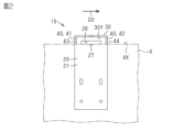
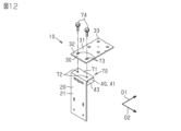
- FIG. 2 is a perspective view of the anchor support of the first embodiment.
- FIG. 2 is a rear view of the anchor support of the first embodiment.
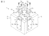
- FIG. 2 is a perspective view of an anchor support for an outside corner in the first embodiment.
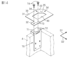
- FIG. 2 is an exploded perspective view of the anchor support for an inside corner in the first embodiment.
- FIG. 2 is a plan view of a foundation on which the anchor support of the first embodiment is installed.
- FIG. 2 is a perspective view of the anchor support of the first embodiment installed in a formwork.
- FIG. 2 is a first cross-sectional view of a foundation in the anchor installation method of the first embodiment.
- FIG. 11 is a second cross-sectional view of the foundation in the anchor installation method of the first embodiment.
- FIG. 11 is a third cross-sectional view of the foundation in the anchor installation method of the first embodiment.
- FIG. 11 is a fourth cross-sectional view of the foundation in the anchor installation method of the first embodiment.
- FIG. 11 is a fifth cross-sectional view of the foundation in the anchor installation method of the first embodiment.
- FIG. 11 is an exploded perspective view of the anchor support of the second embodiment.
- FIG. 11 is an exploded perspective view of an anchor support for an outside corner in a second embodiment.
- FIG. 11 is an exploded perspective view of an inside corner anchor support according to a second embodiment.
- FIG. 11 is a plan view of a foundation on which the anchor support of the second embodiment is installed.
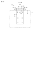
- FIG. 13 is a rear view of the anchor support of the modified example.
- the anchor support 10 and the anchor installation method of the present embodiment will be described with reference to Figures 1 to 11.
- the anchor support 10 is used when constructing a foundation 1.
- An example of the foundation 1 is a slab foundation.
- Figure 11 illustrates the case where the foundation 1 is a slab foundation.
- the foundation 1 is composed of concrete 2 and reinforcing bars 3.
- the foundation 1 is formed by pouring the concrete 2 into a formwork 4.
- the formwork 4 is composed of a frame plate 5.
- the frame plate 5 is installed so as to surround the outer periphery of the foundation 1 to be constructed.
- the frame plate 5 is supported by support rods 7 on the ground 6.
- Anchor 8 is provided on foundation 1. Anchor 8 is provided so that a portion of anchor 8 is exposed from foundation 1. Portion 8B of anchor 8 other than exposed portion 8A is buried in concrete 2 that constitutes foundation 1. Exposed portion 8A of anchor 8 is connected to a column of the main body of the building that is erected on foundation 1. In one example, anchor 8 is installed along the outer periphery of foundation 1.
- the anchor support 10 shown in this embodiment can be suitably used for slab foundations.
- the foundation 1 is a slab foundation
- the formwork 4 corresponding to the rising part of the slab foundation has two frame plates 5 installed parallel to each other. Therefore, the anchor 8 placed between the two frame plates 5 can be supported by a support member supported by the two frame plates 5.
- the frame plate 5 is installed so as to surround the outer periphery of the foundation 1. Therefore, the anchor support 10 supporting the anchor 8 is fixed to the frame plate 5 in a cantilevered state.
- the anchor support 10 of this embodiment can be suitably used.
- the anchor support 10 is a jig for installing an anchor 8 in a foundation 1.
- a plurality of anchor supports 10 may be used for the foundation 1.
- the anchor support 10 supports the anchor 8 provided in the foundation 1.
- the anchor support 10 is used in the construction of the foundation 1 at a stage where the anchor 8 is installed in the foundation 1 after the formwork 4 of the foundation 1 is installed and before the concrete 2 is poured into the formwork 4.
- the anchor support 10 includes a formwork mounting part 20, an anchor support part 30, and a main body support part 40.
- the formwork mounting part 20, the anchor support part 30, and the main body support part 40 are made of, for example, metal.
- the formwork mounting part 20 is attached to the outer surface 4A of the formwork 4 of the foundation 1.
- the formwork mounting part 20 is attached to the outer surface 4A of the formwork 4, thereby fixing the anchor support 10 to the formwork 4.
- the formwork mounting part 20 has a mounting plate-shaped member 21.
- the mounting plate-shaped member 21 extends along the outer surface 4A of the formwork 4.
- the mounting plate-shaped member 21 is attached to the formwork 4 by a first fastening member 22.
- the mounting plate-shaped member 21 may be attached to the formwork 4 by a first additional fastening member 23 in addition to the first fastening member 22.
- the mounting plate member 21 is provided with a first mounting hole 24 formed to extend in the vertical direction.
- the mounting plate member 21 is provided with two first mounting holes 24.
- a first fastening member 22 is placed in the first mounting hole 24.
- the first fastening member 22 is, for example, a screw. Because the first mounting hole 24 is an elongated hole extending in the vertical direction, when the first fastening member 22 is inserted through the first mounting hole 24, the anchor support 10 can move in the vertical direction relative to the formwork 4.
- the mounting plate member 21 may be provided with a first additional mounting hole 25.
- the mounting plate member 21 is provided with two first additional mounting holes 25.
- a first additional fastening member 23 is placed in the first additional mounting hole 25.
- the first additional fastening member 23 is, for example, a screw. After the position of the anchor support 10 in the vertical direction is adjusted by the first mounting hole 24, the first additional fastening member 23 is placed in the first additional mounting hole 25, thereby fixing the formwork mounting part 20 to the outer surface 4A of the formwork 4.
- the first additional fastening member 23 may be omitted.
- an opening 26 is provided in the mounting plate member 21.
- the opening 26 is located between the upper surface 4X of the formwork 4 and the lower surface 30Y of the anchor support part 30 in the vertical direction.
- the opening 26 is provided so that when the anchor support 10 is placed in the formwork 4, the upper surface 4X of the formwork 4 can be seen through the opening 26 from outside the formwork 4.
- a reference mark 27 for the installation position of the anchor 8 is provided in the opening 26.
- the reference mark 27 is configured as a recess provided on the edge of the opening 26.
- the reference mark 27 may also be configured as a protrusion provided on the edge of the opening 26, or as an engraved mark displayed on the edge of the opening 26 with paint or the like.
- the reference mark 27 is used to adjust the position of the anchor support 10.
- the anchor support part 30 extends from the formwork mounting part 20 and supports the anchor 8.
- the anchor support part 30 has an anchor support plate-like member 31 extending from the formwork mounting part 20 in a first direction D1.
- the first direction D1 is a direction perpendicular to a surface of the mounting plate-like member 21 that contacts the outer surface 4A of the formwork 4.
- the anchor support part 30 is formed integrally with the formwork mounting part 20 and the main body support part 40.
- the anchor support plate-like member 31 and the mounting plate-like member 21 are formed by a single plate.
- the anchor support part 30 may be formed integrally with the formwork mounting part 20 by welding the anchor support plate-like member 31 and the mounting plate-like member 21 to each other.
- the anchor support part 30 has a base 32 and an anchor mounting part 33.
- the base 32 is connected to the formwork mounting part 20.
- the base 32 is provided near the end of the anchor support plate member 31 that is located on the mounting plate member 21 side in the first direction D1.
- the base 32 includes a portion of the anchor support plate member 31 that is connected to the mounting plate member 21.
- the anchor mounting portion 33 is located opposite the base portion 32 in the first direction D1.
- An anchor 8 is attached to the anchor mounting portion 33.
- the anchor mounting portion 33 is provided near the end of the anchor support plate member 31 that is located opposite the base portion 32 in the first direction D1.
- the anchor mounting portion 33 is provided with an anchor hole 34 through which the anchor 8 can be inserted.
- the anchor support portion 30 is provided with four anchor holes 34.
- the four anchor holes 34 are arranged so that the shape formed by the four anchor holes 34 forms a square.
- the anchor 8 is arranged in two of the four anchor holes 34 that are located on a diagonal line.
- the anchors 8 arranged in the anchor holes 34 are fastened to the anchor support plate member 31 by nuts 8C.
- the anchor mounting portion 33 is provided with an anchor reference portion 35.
- the four anchor holes 34 are arranged at equal distances from the anchor reference portion 35.
- the anchor reference portion 35 is used as a mark indicating the reference position of the anchor support portion 30.
- the anchor reference portion 35 is used to adjust the position of the anchor support 10 before the anchor support 10 is fixed to the formwork 4.
- the anchor reference portion 35 is used as the reference position of the anchor support portion 30 when checking the positional deviation between the reference line L stretched against the foundation 1 and the anchor support portion 30.
- the reference line L is, for example, a water line or a marking.
- the anchor reference portion 35 is configured as a hole that penetrates the anchor support plate member 31.
- the anchor reference portion 35 may be configured as a depression or an engraved mark. The anchor reference portion 35 allows the anchor 8 to be installed in accordance with the reference line L.
- the reference mark 27 of the opening 26 passes through the anchor reference portion 35 in a plan view and is on a straight line extending along the first direction D1.
- the reference mark 27 is in the same position as the anchor reference portion 35 in the second direction D2, and is therefore useful for adjusting the position of the anchor support 10 using the anchor reference portion 35.
- the position of the anchor support 10 is adjusted so that the reference mark 27 matches a construction reference auxiliary line drawn on the upper surface 4X of the formwork 4.
- the reference auxiliary line is drawn based on the reference line L.
- the main body support part 40 is provided on the lower surface 30Y of the anchor support part 30 so as to support the anchor support part 30 in the formwork 4.
- the main body support part 40 is configured to be disposed on the upper surface 4X of the formwork 4.
- the main body support part 40 is configured so that the anchor support 10 can stand on its own on the upper surface 4X of the formwork 4 by disposing the main body support part 40 on the upper surface 4X of the formwork 4.
- the main body support part 40 supports the anchor support part 30 so that the anchor support part 30 is located above the foundation 1 so that a worker can level the surface of the concrete 2 that forms the foundation 1.
- the body support part 40 has a first body support part 41 and a second body support part 42.
- the first body support part 41 and the second body support part 42 are provided on the lower surface 30Y of the anchor support part 30 and are configured to be disposed on the upper surface 4X of the formwork 4.
- the second body support part 42 is provided away from the first body support part 41.
- the first body support part 41 is provided at one end of the lower surface 30Y of the anchor support part 30 in the second direction D2.
- the second body support part 42 is provided at the other end of the lower surface 30Y of the anchor support part 30 in the second direction D2.
- the second direction D2 is a direction that intersects with the first direction D1. Specifically, the second direction D2 is perpendicular to the first direction D1 in a plan view when the anchor support 10 is installed in the formwork 4.
- the first body support part 41 has a first support plate member 43 extending in the vertical direction.
- the second body support part 42 has a second support plate member 44 extending in the vertical direction.
- the first support plate member 43 and the second support plate member 44 are formed integrally with the mounting plate member 21.
- the first support plate member 43 and the second support plate member 44 are formed integrally with the anchor support plate member 31.
- the width of the mounting plate member 21 in the first direction D1 is equal to or shorter than the width of the formwork 4 in the first direction D1.
- the anchor support 10 for outside corners and the anchor support 10 for inside corners will be described with reference to Figures 3 and 4.
- the anchor support 10 described above will be referred to as a normal anchor support 10 to distinguish it from the anchor support 10 for outside corners and the anchor support 10 for inside corners.
- the outside corner 1CX of the foundation 1 refers to a corner that protrudes outward when viewed from the outside of the foundation 1.
- the inside corner 1CY of the foundation 1 refers to a corner that protrudes inward when viewed from the outside of the foundation 1.
- ⁇ Anchor support for outside corners> 3 illustrates an example of an anchor support 10 for an external corner.
- the anchor support 10 for an external corner is used to support an anchor 8 placed near an external corner of a foundation 1.
- the anchor support 10 for an external corner is configured similarly to the normal anchor support 10, except that the anchor support portion 30 has a notch portion 50, the configuration of the anchor hole 34, and the configuration of the anchor reference portion 35.
- the anchor support part 30 for an external corner has a notch 50.
- the notch 50 is a portion that is formed to be notched in the anchor support plate member 31 of the anchor support part 30.
- the notch 50 is provided between the base 32 and the anchor mounting part 33 of the anchor support part 30.
- a part of the notch 50 may be provided to overlap a part of the anchor mounting part 33.
- the cutout portion 50 is provided so as to overlap a portion of the anchor support plate member 31 where an anchor hole 34 is provided in a normal anchor support 10.
- the cutout portion 50 is disposed in a portion where one anchor hole 34 is provided in a normal anchor support 10. For this reason, three anchor holes 34 are provided in the anchor support plate member 31 of the anchor support 10 for an outside corner.
- the notch 50 is formed at the end of the anchor support plate member 31 in the second direction D2.
- the notch 50 is formed at the end of the anchor support plate member 31 on the side of the second body support portion 42, but it may also be formed at the end of the anchor support plate member 31 on the side of the first body support portion 41.
- the corner 51 of the cutout 50 has an anchor reference portion 35.
- the cutout 50 has a first edge 52A and a second edge 52B continuing from the corner 51.
- the first edge 52A is perpendicular to the second edge 52B.
- the first edge 52A and the second edge 52B are configured as references for adjusting the position of the anchor support 30 for an external corner.
- the anchor support 10 for an external corner is installed in the formwork 4, the first edge 52A and the second edge 52B continuing from the corner 51 are overlapped with the reference line L in a plan view.
- ⁇ Anchor support for inside corners> 4 illustrates an inside corner anchor support 10.
- the inside corner anchor support 10 is used to support an anchor 8 placed near an inside corner of a foundation 1.
- the inside corner anchor support 10 is configured in the same manner as the normal anchor support 10, except that it includes an additional anchor support portion 60 and that the additional anchor support portion 60 is attached to the anchor mounting portion 33.
- the anchor support 10 for an inside corner further includes an additional anchor support part 60.
- the additional anchor support part 60 is supported by the anchor support part 30.
- the additional anchor support part 60 supports the anchor 8.
- the additional anchor support part 60 has an additional anchor support plate member 61 arranged to extend from the anchor support part 30 in the second direction D2.
- the additional anchor support section 60 has an additional base section 62 and an additional anchor mounting section 63.
- the additional base section 62 is provided at the end section of the additional anchor support plate-shaped member 61 on the anchor support section 30 side in the second direction D2.
- the additional anchor mounting section 63 is provided at the end section of the additional anchor support plate-shaped member 61 opposite the additional base section 62 in the second direction D2.
- the additional base 62 is attached to the anchor mounting portion 33 of the anchor support portion 30.
- a second additional mounting hole 64 is provided in the additional base 62.
- a second additional fastening member 65 is disposed in the second additional mounting hole 64.
- the second additional fastening member 65 is, for example, a bolt and a nut.
- the second additional fastening member 65 is inserted through the second additional mounting hole 64 and the engagement hole 66 of the anchor support portion 30.
- the anchor hole 34 of the anchor support portion 30 is configured to double as the engagement hole 66.
- the second additional mounting hole 64 is an elongated hole formed to extend in the second direction D2. Because the second additional mounting hole 64 is an elongated hole, when the second additional fastening member 65 is disposed in the second additional mounting hole 64 and the engagement hole 66, the additional anchor support part 60 can move in the second direction D2 relative to the anchor support part 30. After the second additional fastening member 65 temporarily fastens the additional anchor support plate member 61 and the anchor support plate member 31, the position of the additional anchor support part 60 is fine-adjusted. After the position of the additional anchor support part 60 is fine-adjusted to match the reference line L, etc., the second additional fastening member 65 permanently fastens the additional anchor support plate member 61 and the anchor support plate member 31.
- the additional anchor mounting portion 63 is located opposite the additional base portion 62 in the second direction D2, and has an anchor 8 attached thereto.
- the additional anchor mounting portion 63 is provided with an additional anchor hole 67 through which the anchor 8 can be inserted.
- the additional anchor support portion 60 is provided with four additional anchor holes 67.
- the four additional anchor holes 67 are arranged so that the shape formed by the four additional anchor holes 67 forms a square.
- the additional anchor mounting portion 63 is provided with an additional anchor reference portion 68.
- the four additional anchor holes 67 are arranged at equidistant positions from the additional anchor reference portion 68.
- the additional anchor reference portion 68 is used as a mark indicating the reference position of the additional anchor support portion 60.
- the additional anchor reference portion 68 is used to adjust the position of the additional anchor support portion 60 before the additional anchor support portion 60 is fixed to the anchor support 10.
- the additional anchor reference portion 68 is configured as a hole penetrating the additional anchor support plate member 61.
- the additional anchor reference portion 68 may be configured as a recess or an engraved mark.
- a reference line L is stretched on the ground 6 on which the foundation 1 is constructed to indicate the position at which the anchor 8 is to be installed.
- the reference line L includes a first reference line L1 and a second reference line L2.
- the second reference line L2 is stretched so as to be perpendicular to the first reference line L1.
- the intersection point P is the point where the first reference line L1 and the second reference line L2 intersect.
- the intersection point P is located near an outside corner of the foundation 1 or near an inside corner of the foundation 1.
- FIG. 5 shows the state in which each of the multiple anchor supports 10 is arranged in a predetermined position.
- the anchor support 10 for an outside corner is arranged at the outside corner 1CX of the foundation 1.
- the anchor support 10 for an inside corner is arranged at the inside corner 1CY of the foundation 1.
- the anchor support 10 for normal use is arranged at a position between the outside corner 1CX and the inside corner 1CY.
- the anchor supports 10 for outside corners and inside corners are positioned so that the anchor reference portion 35 of the anchor mounting portion 33 overlaps with the intersection P of the first reference line L1 and the second reference line L2.
- the anchor supports 10 for normal use are positioned so that the anchor reference portion 35 of the anchor mounting portion 33 is located on the first reference line L1.
- the anchor supports 10 for normal use may be positioned so that the anchor reference portion 35 of the anchor mounting portion 33 is located on the second reference line L2.
- an anchor 8 is attached to the anchor support portion 30 of the anchor support 10 placed in a predetermined position.
- the anchor 8 inserted into the anchor hole 34 of the anchor mounting portion 33 is fixed to the anchor support portion 30 by a nut 8C. Since the anchor support 10 is placed in a predetermined position relative to the foundation 1, the anchor 8 can be placed in a predetermined position on the foundation 1 simply by inserting the anchor 8 into the anchor support portion 30.
- the anchor installation method is a method of installing anchors 8 in formwork 4 of a foundation 1.
- the anchor installation method is used in the construction of the foundation 1.
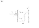
- FIG. 7 shows the state in which formwork 4 has been installed on ground 6 before anchors 8 are installed in foundation 1.
- a trench 6A is provided in ground 6.
- Formwork 4 is installed so as to surround foundation 1 to be constructed.
- Formwork 4 is arranged outside groove 6A so as to run along groove 6A.
- Reinforcing bars 3 are provided along groove 6A. Reinforcing bars 3 are also arranged over the entire surface of ground 6 on which foundation 1 is to be installed.
- a reference line L is laid on the ground 6 on which the foundation 1 is to be provided.
- the first reference line L1 is laid so as to be a predetermined distance away from the formwork 4 and to run along the formwork 4.
- the second reference line L2 is also laid so as to be a predetermined distance away from the formwork 4 and to run along the formwork 4.
- the second reference line L2 is laid so as to be perpendicular to the first reference line L1.
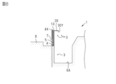
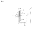
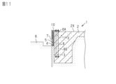
- FIGS. 8 to 10 are diagrams showing the anchor installation method.
- the anchor installation method includes a first step, a second step, a third step, and a fourth step.
- the main body support part 40 that supports the anchor support 10 is placed on the upper surface 4X of the formwork 4.
- the position of the anchor support 10 relative to the formwork 4 is adjusted.
- the formwork mounting part 20 of the anchor support 10 is attached to the outer surface 4A of the formwork 4 of the foundation 1.
- the anchor 8 is attached to the anchor support part 30.
- the main body support part 40 that supports the anchor support 10 is placed on the upper surface 4X of the formwork 4.
- the anchor support 10 stands on its own on the upper surface 4X of the formwork 4 by the main body support part 40.
- the main body support part 40 forms a gap between the lower surface 30Y of the anchor support part 30 and the upper surface 2X of the concrete 2. This gap is such that the surface of the concrete 2 located below the anchor support part 30 can be leveled after the concrete 2 has been poured.
- the position of the anchor support 10 relative to the formwork 4 is adjusted.
- the position of the anchor support 10 relative to the formwork 4 in the horizontal direction is adjusted.
- the reference mark 27 of the opening 26 and the anchor reference portion 35 of the anchor support portion 30 are aligned with the reference line L, thereby positioning the multiple anchor supports 10 in predetermined positions.
- the position of the anchor support 10 relative to the formwork 4 in the vertical direction may be adjusted by the first mounting hole 24.
- the formwork mounting portion 20 of the anchor support 10 is attached to the outer surface 4A of the formwork 4 of the foundation 1.
- the formwork mounting portion 20 of the anchor support 10 which has been placed in a predetermined position, is temporarily fixed to the outer surface 4A of the formwork 4 of the foundation 1 by the first fastening member 22.
- the height of the anchor support portion 30 is fine-tuned by the first mounting hole 24, and then it is permanently fixed by the first additional fastening member 23.
- the anchor 8 is attached to the anchor support part 30.
- the anchor 8 is fixed to the anchor support part 30 by the nut 8C.
- concrete 2 is poured into the formwork 4.
- the upper surface 2X of the concrete 2 is leveled with a drill or a trowel.
- the portion of the upper surface 2X of the concrete 2 below the anchor support portion 30 is leveled using, for example, a trowel.
- the anchor support 10 can be placed on the upper surface 4X of the formwork 4 by the main support part 40 before the anchor support 10 is fixed to the formwork 4.
- a worker can align the position of the anchor support part 30 with the reference line L and then fix the formwork mounting part 20 to the formwork 4.
- the main support part 40 allows the anchor support 10 to stand independently on the upper surface 4X of the formwork 4
- the work from adjusting the position of the anchor support part 30 to attaching the formwork mounting part 20 to the outer surface 4A of the formwork 4 can be performed by a small number of workers.
- the multiple anchor supports 10 installed on the formwork 4 are each independent, it is easy to align the position of the anchor support part 30 of each anchor 8 with the reference line L when installing the anchor support 10 on the formwork 4.
- the first mounting hole 24 allows adjustment of the position of the anchor support 10 in the up-down direction.
- the position of the anchor support part 30 in the first direction D1 outside the formwork 4 can be adjusted.
- a fourth function of this embodiment will be described.
- the cutout portion 50 makes it easy to check the filling status of the concrete 2 in the outside corner 1CX of the foundation 1.
- the cutout portion 50 makes it easy to check the filling status of the concrete 2 in the inside corner 1CY of the foundation 1.
- the anchor support 10 supports an anchor 8 provided in a foundation 1.
- the anchor support 10 includes a formwork mounting portion 20, an anchor support portion 30, and a main body support portion 40.
- the formwork mounting portion 20 is attached to an outer surface 4A of a formwork 4 of the foundation 1.
- the anchor support portion 30 extends from the formwork mounting portion 20 and supports the anchor 8.
- the main body support portion 40 is provided on a lower surface 30Y of the anchor support portion 30 so as to support the anchor support portion 30 in the formwork 4.
- the main body support portion 40 is configured to be disposed on an upper surface 4X of the formwork 4.
- the anchor support 10 can be installed on the upper surface 4X of the formwork 4 by the main support part 40.
- the formwork mounting part 20 can be attached to the formwork 4, making it easy to install the anchor support 10 on the formwork 4. Therefore, the anchor support 10 can improve the work efficiency of installing the anchor 8.
- the body support part 40 has a first body support part 41 and a second body support part 42 that is provided at a distance from the first body support part 41.
- the first body support part 41 and the second body support part 42 are provided at a distance from each other, so that the anchor support 10 is stable when the anchor support 10 is installed on the upper surface 4X of the formwork 4.
- the formwork mounting part 20 has a mounting plate member 21 that extends along the outer surface 4A of the formwork 4.
- the mounting plate member 21 has an opening 26 that is located between the upper surface 4X of the formwork 4 and the lower surface 30Y of the anchor support part 30 in the vertical direction.
- a reference mark 27 for the installation position of the anchor 8 is provided in the opening 26.
- the formwork mounting part 20 has a mounting plate member 21 that extends along the outer surface 4A of the formwork 4.
- the mounting plate member 21 is provided with a first mounting hole 24 that is formed to extend in the vertical direction.
- the anchor support part 30 is formed integrally with the formwork mounting part 20 and the main body support part 40. With this configuration, the anchor support part 30 is formed integrally with the formwork mounting part 20 and the main body support part 40, making the anchor support 10 easier to handle. Compared to conventional anchor installation methods, with the anchor support 10, the anchor support part 30 is formed integrally with the formwork mounting part 20 and the main body support part 40, making it possible to reduce the types and quantity of jigs, etc., compared to conventional methods. As a result, the anchor support 10 can reduce management costs such as the creation, storage, and maintenance of jigs.
- the anchor support part 30 has a base 32 and an anchor mounting part 33.
- the base 32 is connected to the formwork mounting part 20.
- the anchor mounting part 33 is located opposite the base 32 in the first direction D1.
- the anchor 8 is attached to the anchor mounting part 33.
- the anchor mounting part 33 has an anchor hole 34 formed therein through which the anchor 8 can be inserted. With this configuration, the anchor hole 34 is formed in the anchor mounting part 33 on the opposite side to the base 32, so that the anchor 8 can be supported inside the formwork 4.
- the anchor support portion 30 has a notch 50.
- the notch 50 is provided between the base 32 and the anchor mounting portion 33 of the anchor support portion 30.
- the anchor support 10 further includes an additional anchor support part 60.
- the additional anchor support part 60 is supported by the anchor support part 30.
- the additional anchor support part 60 has an additional base part 62 and an additional anchor mounting part 63.
- the additional base part 62 is mounted to the anchor mounting part 33 of the anchor support part 30.
- the additional anchor mounting part 63 is located opposite the additional base part 62 in the second direction D2 intersecting with the first direction D1, and has an anchor 8 mounted thereon.
- the additional anchor mounting part 63 has an additional anchor hole 67 through which the anchor 8 can be inserted.
- the anchor 8 can be supported at a position shifted from the anchor mounting part 33 in the second direction D2 inside the formwork 4.
- the anchor support 10 can support the anchor 8 arranged in the inside corner 1CY of the foundation 1 in a suitable position.
- the inside corner 1CY in which the anchor 8 is arranged can be suitably filled with concrete 2.
- the anchor installation method is a method for installing an anchor 8 in the formwork 4 of a foundation 1.
- the anchor installation method includes a first step, a second step, a third step, and a fourth step.
- the first step the main body support part 40 that supports the anchor support 10 is placed on the upper surface 4X of the formwork 4.
- the second step the position of the anchor support 10 relative to the formwork 4 is adjusted.
- the formwork mounting part 20 of the anchor support 10 is attached to the outer surface 4A of the formwork 4 of the foundation 1.
- the anchor 8 is attached to the anchor support part 30 of the anchor support 10.
- the position of the anchor support 10 can be adjusted when the anchor support 10 is installed on the upper surface 4X of the formwork 4 by the main support part 40. Furthermore, after adjusting the position of the anchor support 10, the anchor support 10 can be attached to the formwork 4. This makes it easy to install the anchor support 10 on the formwork 4. Because the position of the anchor support 10 can be adjusted when it is installed, the anchor support 10 can improve the work efficiency of installing the anchor 8.
- the anchor support section 30 is configured separately from the formwork mounting section 20 and the main body support section 40.
- the anchor support plate member 31 in this embodiment is configured separately from the mounting plate member 21, the first support plate member 43, and the second support plate member 44.
- the anchor support 10 of this embodiment includes an installation section 70.
- the installation section 70 is placed on the formwork 4.
- the installation section 70 is composed of a formwork mounting section 20 and a main body support section 40.
- the base 32 of the anchor support section 30 is connected to the installation section 70.
- the main body support part 40 has a support plate member 71.
- the support plate member 71 is connected to the formwork mounting part 20 and supports the anchor support part 30.
- the support plate member 71 is integrally formed with the mounting plate member 21, the first support plate member 43, and the second support plate member 44.
- the first main body support part 41 is provided at one end of the support plate member 71 in the second direction D2.
- the second main body support part 42 is provided at the other end of the support plate member 71 in the second direction D2.
- the support plate member 71 is provided with a second mounting hole 72.
- the support plate member 71 is provided with two second mounting holes 72.
- the anchor support part 30 is provided with a third mounting hole 73 formed to extend horizontally.
- the third mounting hole 73 is formed in the anchor support plate member 31 to extend in the first direction D1.
- the second fastening member 74 is placed in the second mounting hole 72 and the third mounting hole 73, thereby connecting the anchor support part 30 to the formwork mounting part 20 and the main body support part 40.
- the third mounting hole 73 is an elongated hole formed to extend in the first direction D1. Because the third mounting hole 73 is an elongated hole, when the second fastening member 74 is disposed in the second mounting hole 72 and the third mounting hole 73, the anchor support plate member 31 can move in the first direction D1 relative to the support plate member 71. After the second fastening member 74 temporarily fastens the anchor support plate member 31 and the support plate member 71, the position of the anchor support part 30 is fine-adjusted. After the position of the anchor support part 30 is fine-adjusted to match the reference line L, etc., the second fastening member 74 permanently fastens the anchor support plate member 31 and the support plate member 71.
- the anchor support 10 for an outside corner and the anchor support 10 for an inside corner in this embodiment will be described with reference to Figures 13 and 14.
- the shape of the anchor support portion 30 is different from that of the normal anchor support 10 in this embodiment.
- ⁇ Anchor support for outside corners> 13 illustrates an anchor support 10 for an external corner.
- the anchor support 10 for an external corner of this embodiment has two installation parts 70.
- the two installation parts 70 are installed on each of two frame plates 5 that intersect perpendicularly to form an external corner 1CX of the formwork 4.
- the two installation parts 70 have a first installation part 70A and a second installation part 70B.
- the base 32 of the anchor support part 30 has a first base part 80 and a second base part 81.
- the first base part 80 is connected to the first installation part 70A.
- the second base part 81 is connected to the second installation part 70B.
- the cutout portion 50 of the anchor support portion 30 for an external corner in this embodiment has a first cutout portion 82 and a second cutout portion 83.
- the first cutout portion 82 is provided between the first base portion 80 and the anchor mounting portion 33 of the anchor support plate member 31.
- the second cutout portion 83 is provided between the second base portion 81 and the anchor mounting portion 33 of the anchor support plate member 31.
- the first cutout portion 82 and the second cutout portion 83 form an opening in the anchor support plate member 31.
- ⁇ Anchor support for inside corners> 14 illustrates an inside corner anchor support 10.
- an anchor mounting portion 33 is provided on an end portion of an anchor support plate-shaped member 31 opposite to a base portion 32 in both the first direction D1 and the second direction D2.
- an inside corner opening 90 is provided in the anchor support plate-shaped member 31.
- the anchor support 10 of this embodiment is also arranged so that the anchor reference portion 35 overlaps with the reference line L.
- the edges of the first notch portion 82 and the second notch portion 83 are configured as references for adjusting the position of the anchor support portion 30 for an external corner.
- one edge of the first notch portion 82 and the second notch portion 83 is aligned with the first reference line L1.
- the other edge of the first notch portion 82 and the second notch portion 83 is aligned with the second reference line L2. In this way, the position of the anchor support portion 30 can be aligned with the reference line L.
- the edge of the inside corner opening 90 is configured as a reference for adjusting the position of the inside corner anchor support part 30.
- the position of the anchor support part 30 can be aligned with the reference line L by aligning the edge of the inside corner opening 90 with the first reference line L1 and the second reference line L2.
- ⁇ Action of this embodiment A first function of this embodiment will be described.
- the position of the anchor support part 30 in the first direction D1 can be adjusted by the second mounting hole 72.
- the position of the anchor support part 30 can be aligned with the reference line L. Since the position of the anchor support part 30 relative to the installation part 70 can be adjusted after the formwork mounting part 20 is attached to the formwork 4, the position of the anchor support part 30 can be suitably adjusted.
- the filling status of the concrete 2 in the outside corner 1CX of the foundation 1 can be easily checked by the first notch portion 82 and the second notch portion 83.
- the filling status of the concrete 2 in the inside corner 1CY of the foundation 1 can be easily checked from the inside corner opening 90. Also, it is easy to insert a concrete vibrator into the concrete 2 constituting the outside corner 1CX of the foundation 1 from the first notch portion 82 and the second notch portion 83. It is easy to insert a concrete vibrator into the concrete 2 constituting the inside corner 1CY of the foundation 1 from the inside corner opening 90.
- the anchor support part 30 is configured separately from the formwork mounting part 20 and the main body support part 40.
- the main body support part 40 is connected to the formwork mounting part 20 and has a support plate-like member 71 that supports the anchor support part 30.
- a second mounting hole 72 is provided in the support plate-like member 71.
- a third mounting hole 73 is provided in the anchor support part 30 and is formed to extend in the horizontal direction.
- the anchor support part 30 is connected to the formwork mounting part 20 and the main body support part 40 by inserting the second fastening member 74 through the second mounting hole 72 and the third mounting hole 73. Because the third mounting hole 73 is formed to extend horizontally, the position of the anchor support part 30 in the horizontal direction can be suitably adjusted when the second fastening member 74 is inserted through the second mounting hole 72 and the third mounting hole 73.
- the above embodiment is an example of a form that the anchor support 10 and the anchor installation method can take, and is not intended to limit the form.
- the anchor support 10 and the anchor installation method can take a form different from the form exemplified in the above embodiment. Examples of such a form include a form in which a part of the configuration of the embodiment is replaced, changed, or omitted, or a form in which a new configuration is added to the embodiment. Modified examples of the embodiment are shown below.
- the anchor support 10 may further include a spacer 45.
- the spacer 45 adjusts the height of the anchor support portion 30 relative to the upper surface 4X of the formwork 4.
- the spacer 45 is made of, for example, wood, a resin member, metal, or the like.
- the spacer 45 is inserted between the upper surface 4X of the formwork 4 and at least one of the first body support portion 41 and the second body support portion 42. In the example of Fig. 2, the spacer 45 is inserted between the upper surface 4X of the formwork 4 and both the first body support portion 41 and the second body support portion 42.
- the spacer 45 has a first spacer portion 46 and a second spacer portion 47.
- the first spacer portion 46 is a portion of the spacer 45 that is inserted between the upper surface 4X of the formwork 4 and the first body support portion 41.
- the second spacer portion 47 is a portion of the spacer 45 that is inserted between the upper surface 4X of the formwork 4 and the second body support portion 42.
- the first spacer portion 46 and the second spacer portion 47 are integrally formed.
- the first spacer portion 46 and the second spacer portion 47 may be formed separately.
- One of the first spacer portion 46 and the second spacer portion 47 may be omitted.
- the inclination of the anchor support portion 30 can be suitably adjusted by adjusting the height of the first spacer portion 46 and the second spacer portion 47.
- the position of the anchor support 10 relative to the formwork 4 in the vertical direction may be adjusted by the spacer 45.
- the spacer 45 is inserted into the gap between the upper surface 4X of the formwork 4 and the main body support part 40.
- Spacers 45 of different thicknesses may be prepared in advance. In this case, a spacer 45 with a thickness equal to the height to which the anchor support 10 is to be raised is selected.
- the spacer 45 of the desired thickness may be formed by cutting with a plane.
- the anchor support 10 further includes a spacer 45.
- the spacer 45 adjusts the height of the anchor support portion 30 relative to the upper surface 4X of the formwork 4.
- the spacer 45 is inserted between the upper surface 4X of the formwork 4 and at least one of the first main body support portion 41 and the second main body support portion 42. With this configuration, the spacer 45 can adjust the height of the anchor support portion 30 relative to the upper surface 4X of the formwork 4.
- the height of the anchor support portion 30 can be suitably adjusted to make it easier to level the upper surface 2X of the concrete 2 of the foundation 1.
- the configuration of the first body support part 41 and the second body support part 42 may be changed as desired as long as the first body support part 41 and the second body support part 42 can be arranged on the upper surface 4X of the formwork 4.
- the first body support part 41 and the second body support part 42 may be configured as an integral part.
- the opening 26 may be omitted from the mounting plate member 21 .
- the reference mark 27 may be omitted from the opening 26 .
- the first mounting hole 24 does not have to be formed to extend in the up-down direction. In this modification, the first mounting hole 24 is not formed as a long hole. Alternatively, the first mounting hole 24 may be omitted from the mounting plate member 21.
- the support plate member 71 is provided with a circular second mounting hole 72.
- the anchor support plate member 31 of the anchor support part 30 is provided with a third mounting hole 73 formed to extend in the first direction D1.
- the support plate member 71 may be provided with two second mounting holes 72 extending in the first direction D1.
- the anchor support plate member 31 of the anchor support part 30 may be provided with a circular third mounting hole 73.
- the anchor mounting section 33 does not need to have an anchor hole 34.
- the anchor mounting section 33 may be provided with a spring steel that supports the anchor 8 by clamping it.
- the shape of the notch 50 may be changed to match the shape of the anchor support plate member 31.
- the notch 50 may be, for example, a hole provided between the base 32 and the anchor mounting portion 33.
- the anchor support 10 may be made of resin. By making the anchor support 10 out of resin, the weight of the anchor support 10 can be reduced.
- the present specification discloses the following techniques.
- An anchor support for supporting an anchor installed in a foundation comprising: a formwork mounting part attached to an outer surface of a formwork for the foundation; an anchor support part extending from the formwork mounting part and supporting the anchor; and a main body support part provided on an underside of the anchor support part so as to support the anchor support part in the formwork, the main body support part being configured to be positioned on an upper surface of the formwork.
- Appendix 4 The anchor support of any one of Appendices 1 to 3, wherein the formwork mounting portion has a mounting plate-like member extending along the outer surface of the formwork, and the mounting plate-like member is provided with an opening located between the upper surface of the formwork and the lower surface of the anchor support portion in the vertical direction.
- Appendix 8 7. The anchor support device according to any one of Appendices 1 to 6, wherein the anchor support part is configured separately from the formwork mounting part and the main body support part, the main body support part has a support plate-like member connected to the formwork mounting part and supporting the anchor support part, the support plate-like member is provided with a second mounting hole, and the anchor support part is provided with a third mounting hole formed to extend in the horizontal direction.
- An anchor installation method for installing an anchor in a formwork for a foundation including: a first step of arranging a main body support part that supports an anchor support on an upper surface of the formwork; a second step of adjusting a position of the anchor support relative to the formwork; a third step of attaching a formwork mounting part of the anchor support to an outer surface of the formwork for the foundation; and a fourth step of attaching the anchor to the anchor support part of the anchor support.
Landscapes
- Engineering & Computer Science (AREA)
- Architecture (AREA)
- Civil Engineering (AREA)
- Structural Engineering (AREA)
- Mechanical Engineering (AREA)
- Mining & Mineral Resources (AREA)
- Life Sciences & Earth Sciences (AREA)
- General Life Sciences & Earth Sciences (AREA)
- Paleontology (AREA)
- General Engineering & Computer Science (AREA)
- Foundations (AREA)
- Joining Of Building Structures In Genera (AREA)
Abstract
Description
図1~図11を参照して、本実施形態のアンカー支持具10およびアンカー設置方法を説明する。アンカー支持具10は、基礎1の施工時に使用される。アンカー支持具10が適用される基礎1の例は限定されない。基礎1の例として、ベタ基礎が挙げられる。図11では、基礎1がベタ基礎である場合を例示する。
図11に示されるように、アンカー支持具10は、基礎1にアンカー8を設置するための治具である。基礎1には、複数のアンカー支持具10が使用されてもよい。アンカー支持具10は、基礎1に設けられるアンカー8を支持する。アンカー支持具10は、基礎1の施工において、基礎1の型枠4が設置された後、型枠4にコンクリート2が打設される前にアンカー8が基礎1に設置される段階において使用される。
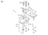
図1および図6に示されるように、型枠取付部20は、基礎1の型枠4の外面4Aに取り付けられる。型枠取付部20が型枠4の外面4Aに取り付けられることによって、アンカー支持具10が型枠4に固定される。型枠取付部20は、取付板状部材21を有する。取付板状部材21は、型枠4の外面4Aに沿って延びる。取付板状部材21は、第1締結部材22によって型枠4に取り付けられる。取付板状部材21は、第1締結部材22に加えて、第1追加締結部材23によって型枠4に取り付けられてもよい。
図1および図6に示されるように、アンカー支持部30は、型枠取付部20から延び、かつ、アンカー8を支持する。アンカー支持部30は、型枠取付部20から第1方向D1に延びるアンカー支持板状部材31を有する。本実施形態では、第1方向D1は、取付板状部材21において型枠4の外面4Aに接触する面に対して垂直な方向である。アンカー支持具10が型枠4に設置された状態において、第1方向D1は、平面視において、アンカー支持具10が設置される型枠4と垂直な方向である。本実施形態では、アンカー支持部30は、型枠取付部20および本体支持部40と一体に形成される。アンカー支持板状部材31と取付板状部材21とは、一枚の板によって形成される。アンカー支持板状部材31と取付板状部材21とが溶接されることによって、アンカー支持部30は、型枠取付部20と一体に形成されてもよい。
図1および図2に示されるように、本体支持部40は、型枠4においてアンカー支持部30を支持するように、アンカー支持部30の下面30Yに設けられる。本体支持部40は、型枠4の上面4Xに配置されるように構成される。本体支持部40は、本体支持部40が型枠4の上面4Xに配置されることによって、アンカー支持具10が型枠4の上面4Xに自立できるように構成される。本体支持部40は、作業者が基礎1を形成するコンクリート2の表面を均せるように、アンカー支持部30が基礎1よりも上に位置するようにアンカー支持部30を支持する。
図3は、出隅用のアンカー支持具10を例示する。出隅用のアンカー支持具10は、基礎1の出隅付近に配置されるアンカー8を支持するために使用される。出隅用のアンカー支持具10は、アンカー支持部30が切欠け部50を有する点、アンカー孔34の構成、およびアンカー基準部35の構成以外は、通常用のアンカー支持具10と同様に構成される。
図4は、入隅用のアンカー支持具10を例示する。入隅用のアンカー支持具10は、基礎1の入隅付近に配置されるアンカー8を支持するために使用される。入隅用のアンカー支持具10は、追加アンカー支持部60を備える点、アンカー取付部33に追加アンカー支持部60が取り付けられる点以外は、通常用のアンカー支持具10と同様に構成される。
図5~図11を参照して、アンカー設置方法を説明する。アンカー設置方法は、基礎1の型枠4にアンカー8を設置する方法である。アンカー設置方法は、基礎1の施工において使用される。
本実施形態の第1の作用を説明する。
アンカー支持具10は、アンカー支持具10を型枠4に固定する前に、本体支持部40によってアンカー支持具10を型枠4の上面4Xに配置できる。作業者は、アンカー支持具10を型枠4の上面4Xに置いた状態において、アンカー支持部30の位置を基準線Lに合わせた後に、型枠取付部20を型枠4に固定できる。本体支持部40によってアンカー支持具10が型枠4の上面4Xに自立できるため、アンカー支持部30の位置の調整から、型枠取付部20を型枠4の外面4Aに取り付けるまでの作業を少ない作業者で行える。また、型枠4に設置される複数のアンカー支持具10は、それぞれが独立しているため、アンカー支持具10を型枠4に設置する際に、各アンカー8に、アンカー支持部30の位置を基準線Lに合わせ易い。
第1取付孔24によって、アンカー支持具10の上下方向における位置調整ができる。また、本体支持部40の型枠4に対する位置を調整することによって、型枠4の外側において、第1方向D1におけるアンカー支持部30の位置を調整できる。
アンカー支持具10を用いるアンカー設置方法では、アンカー支持具10のうちのアンカー支持部30のみがコンクリート2の上に位置するので、従来のアンカー設置方法よりもコンクリート2の表面を均し易い。
従来のアンカー設置方法では、アンカー8を支持するプレートが出隅1CXおよび入隅1CYに設置される場合、出隅1CXおよび入隅1CYにおけるコンクリート2の充填状況が確認し難い。出隅用のアンカー支持具10では、切欠け部50によって、基礎1の出隅1CXにおけるコンクリート2の充填状況を確認し易い。入隅用のアンカー支持具10では、追加アンカー支持部60の横から、基礎1の入隅1CYにおけるコンクリート2の充填状況を確認し易い。また、切欠け部50から基礎1の出隅1CXを構成するコンクリート2にコンクリートバイブレーターを挿入し易い。追加アンカー支持部60の横から基礎1の入隅1CYを構成するコンクリート2にコンクリートバイブレーターを挿入し易い。このように、出隅用および入隅用のアンカー支持具10を使用することによって、基礎1の出隅1CXおよび入隅1CYにコンクリート2を好適に打設できる。
本実施形態の効果を説明する。
(1-1)アンカー支持具10は、基礎1に設けられるアンカー8を支持する。アンカー支持具10は、型枠取付部20と、アンカー支持部30と、本体支持部40と、を備える。型枠取付部20は、基礎1の型枠4の外面4Aに取り付けられる。アンカー支持部30は、型枠取付部20から延び、かつ、アンカー8を支持する。本体支持部40は、型枠4においてアンカー支持部30を支持するように、アンカー支持部30の下面30Yに設けられる。本体支持部40は、型枠4の上面4Xに配置されるように構成される。
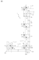
図12から図15を参照して、第2実施形態に係るアンカー支持具10について説明する。なお、本実施形態では、第1実施形態の構成と実質的に変更のない構成については、第1実施形態の構成と同一の符号をつけるとともに、その説明を省略する。
図13は、出隅用のアンカー支持具10を例示する。本実施形態の出隅用のアンカー支持具10は、2つの設置部70を有する。2つの設置部70は、型枠4のうちの出隅1CXを構成するように垂直に交差する2つの枠板5のそれぞれに設置される。2つの設置部70は、第1設置部70Aおよび第2設置部70Bを有する。
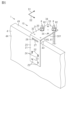
図14は、入隅用のアンカー支持具10を例示する。本実施形態の入隅用のアンカー支持具10は、アンカー取付部33が、アンカー支持板状部材31のうちの第1方向D1および第2方向D2の両方に対して基部32とは反対の端部に設けられる。本実施形態の入隅用のアンカー支持具10では、アンカー支持板状部材31に、入隅開口部90が設けられる。
本実施形態の第1の作用を説明する。
通常用のアンカー支持具10では、第2取付孔72によって、アンカー支持部30の第1方向D1における位置調整ができる。本実施形態では、設置部70に対するアンカー支持部30の位置を調整することによって、アンカー支持部30の位置を基準線Lに合わせることができる。型枠取付部20を型枠4にとりつけた後に、設置部70に対するアンカー支持部30の位置を調整できるため、アンカー支持部30の位置を好適に調整できる。
本実施形態の出隅用のアンカー支持具10では、第1切欠け部82および第2切欠け部83によって、基礎1の出隅1CXにおけるコンクリート2の充填状況を確認し易い。本実施形態の入隅用のアンカー支持具10では、入隅開口部90から、基礎1の入隅1CYにおけるコンクリート2の充填状況を確認し易い。また、第1切欠け部82および第2切欠け部83から基礎1の出隅1CXを構成するコンクリート2にコンクリートバイブレーターを挿入し易い。入隅開口部90から基礎1の入隅1CYを構成するコンクリート2にコンクリートバイブレーターを挿入し易い。
本実施形態の効果を説明する。
(2)アンカー支持部30は、型枠取付部20および本体支持部40と別体に構成される。本体支持部40は、型枠取付部20に接続され、かつ、アンカー支持部30を支持する支持板状部材71を有する。支持板状部材71には、第2取付孔72が設けられる。アンカー支持部30には、水平方向に延びるように形成される第3取付孔73が設けられる。
上記実施形態は、アンカー支持具10およびアンカー設置方法が取り得る形態の例示であり、その形態を制限することを意図していない。アンカー支持具10およびアンカー設置方法は、上記実施形態に例示された形態とは異なる形態を取り得る。その例は、実施形態の構成の一部を置換、変更、省略した形態、または、実施形態に新たな構成を付加した形態である。以下に実施形態の変形例を示す。
・図16に示されるように、アンカー支持具10は、スペーサ45をさらに備えてもよい。スペーサ45は、型枠4の上面4Xに対するアンカー支持部30の高さを調整する。スペーサ45は、例えば木材、樹脂部材、金属等によって構成される。スペーサ45は、型枠4の上面4Xと、第1本体支持部41および第2本体支持部42の少なくとも一方と、の間に挿入される。図2の例では、スペーサ45は、型枠4の上面4Xと、第1本体支持部41および第2本体支持部42の両方と、の間に挿入される。
・第1本体支持部41および第2本体支持部42の構成は、第1本体支持部41および第2本体支持部42が型枠4の上面4Xに配置されることができれば、任意に変更されてもよい。例えば、第1本体支持部41および第2本体支持部42が一体に構成されてもよい。
・開口部26から基準マーク27が省略されてもよい。
・第1取付孔24は、上下方向に延びるように形成されなくてもよい。本変形例では、第1取付孔24が長孔ではないように形成される。または、取付板状部材21から第1取付孔24が省略されてもよい。
本明細書には以下の技術が開示される。
基礎に設けられるアンカーを支持するアンカー支持具であって、前記基礎の型枠の外面に取り付けられる型枠取付部と、前記型枠取付部から延び、かつ、前記アンカーを支持するアンカー支持部と、前記型枠において前記アンカー支持部を支持するように、前記アンカー支持部の下面に設けられる本体支持部と、を備え、前記本体支持部は、前記型枠の上面に配置されるように構成される、アンカー支持具。
前記本体支持部は、第1本体支持部と、前記第1本体支持部から離れて設けられる第2本体支持部と、を有する、付記1に記載のアンカー支持具。
前記型枠の前記上面に対する前記アンカー支持部の高さを調整するスペーサをさらに備え、前記スペーサは、前記型枠の前記上面と、前記第1本体支持部および前記第2本体支持部の少なくとも一方と、の間に挿入される、付記2に記載のアンカー支持具。
前記型枠取付部は、前記型枠の前記外面に沿って延びる取付板状部材を有し、前記取付板状部材には、上下方向において前記型枠の前記上面から前記アンカー支持部の前記下面までの間に位置する開口部が設けられる、付記1~3のいずれか1つに記載のアンカー支持具。
前記開口部には、前記アンカーの設置位置に関する基準マークが設けられる、付記4に記載のアンカー支持具。
前記型枠取付部は、前記型枠の前記外面に沿って延びる取付板状部材を有し、前記取付板状部材には、上下方向に延びるように形成される第1取付孔が設けられる、付記1~3のいずれか1つに記載のアンカー支持具。
前記アンカー支持部は、前記型枠取付部および前記本体支持部と一体に形成される、付記1~6のいずれか1つに記載のアンカー支持具。
前記アンカー支持部は、前記型枠取付部および前記本体支持部と別体に構成され、前記本体支持部は、前記型枠取付部に接続され、かつ、前記アンカー支持部を支持する支持板状部材を有し、前記支持板状部材には、第2取付孔が設けられ、前記アンカー支持部には、水平方向に延びるように形成される第3取付孔が設けられる、付記1~6のいずれか1つに記載のアンカー支持具。
前記アンカー支持部は、前記型枠取付部に接続される基部と、第1方向において、前記基部とは反対に位置するとともに、前記アンカーが取り付けられるアンカー取付部と、を有し、前記アンカー取付部には、前記アンカーが挿通可能なアンカー孔が設けられる、付記1~8のいずれか1つに記載のアンカー支持具。
前記アンカー支持部は、切欠け部を有し、前記切欠け部は、前記アンカー支持部のうちの前記基部と前記アンカー取付部との間に設けられる、付記9に記載のアンカー支持具。
前記アンカー支持部に支持される追加アンカー支持部をさらに備え、前記追加アンカー支持部は、前記アンカー支持部の前記アンカー取付部に取り付けられる追加基部と、前記第1方向と交差する第2方向において、前記追加基部とは反対に位置するとともに、前記アンカーが取り付けられる追加アンカー取付部と、を有し、前記追加アンカー取付部には、前記アンカーが挿通可能な追加アンカー孔が設けられる、付記9または10に記載のアンカー支持具。
基礎の型枠にアンカーを設置するアンカー設置方法であって、アンカー支持具を支持する本体支持部を前記型枠の上面に配置する第1工程と、前記型枠に対する前記アンカー支持具の位置を調整する第2工程と、前記基礎の前記型枠の外面に、前記アンカー支持具の型枠取付部を取り付ける第3工程と、前記アンカー支持具のアンカー支持部に前記アンカーを取り付ける第4工程と、を含む、アンカー設置方法。
Claims (12)
- 基礎に設けられるアンカーを支持するアンカー支持具であって、
前記基礎の型枠の外面に取り付けられる型枠取付部と、
前記型枠取付部から延び、かつ、前記アンカーを支持するアンカー支持部と、
前記型枠において前記アンカー支持部を支持するように、前記アンカー支持部の下面に設けられる本体支持部と、を備え、
前記本体支持部は、前記型枠の上面に配置されるように構成される、
アンカー支持具。 - 前記本体支持部は、第1本体支持部と、前記第1本体支持部から離れて設けられる第2本体支持部と、を有する、
請求項1に記載のアンカー支持具。 - 前記型枠の前記上面に対する前記アンカー支持部の高さを調整するスペーサをさらに備え、
前記スペーサは、前記型枠の前記上面と、前記第1本体支持部および前記第2本体支持部の少なくとも一方と、の間に挿入される、
請求項2に記載のアンカー支持具。 - 前記型枠取付部は、前記型枠の前記外面に沿って延びる取付板状部材を有し、
前記取付板状部材には、上下方向において前記型枠の前記上面から前記アンカー支持部の前記下面までの間に位置する開口部が設けられる、
請求項1~3のいずれか一項に記載のアンカー支持具。 - 前記開口部には、前記アンカーの設置位置に関する基準マークが設けられる、
請求項4に記載のアンカー支持具。 - 前記型枠取付部は、前記型枠の前記外面に沿って延びる取付板状部材を有し、
前記取付板状部材には、上下方向に延びるように形成される第1取付孔が設けられる、
請求項1~3のいずれか一項に記載のアンカー支持具。 - 前記アンカー支持部は、前記型枠取付部および前記本体支持部と一体に形成される、
請求項1~6のいずれか一項に記載のアンカー支持具。 - 前記アンカー支持部は、前記型枠取付部および前記本体支持部と別体に構成され、
前記本体支持部は、前記型枠取付部に接続され、かつ、前記アンカー支持部を支持する支持板状部材を有し、
前記支持板状部材には、第2取付孔が設けられ、
前記アンカー支持部には、水平方向に延びるように形成される第3取付孔が設けられる、
請求項1~6のいずれか一項に記載のアンカー支持具。 - 前記アンカー支持部は、前記型枠取付部に接続される基部と、第1方向において、前記基部とは反対に位置するとともに、前記アンカーが取り付けられるアンカー取付部と、を有し、
前記アンカー取付部には、前記アンカーが挿通可能なアンカー孔が設けられる、
請求項1~8のいずれか一項に記載のアンカー支持具。 - 前記アンカー支持部は、切欠け部を有し、
前記切欠け部は、前記アンカー支持部のうちの前記基部と前記アンカー取付部との間に設けられる、
請求項9に記載のアンカー支持具。 - 前記アンカー支持部に支持される追加アンカー支持部をさらに備え、
前記追加アンカー支持部は、前記アンカー支持部の前記アンカー取付部に取り付けられる追加基部と、前記第1方向と交差する第2方向において、前記追加基部とは反対に位置するとともに、前記アンカーが取り付けられる追加アンカー取付部と、を有し、
前記追加アンカー取付部には、前記アンカーが挿通可能な追加アンカー孔が設けられる、
請求項9または10に記載のアンカー支持具。 - 基礎の型枠にアンカーを設置するアンカー設置方法であって、
アンカー支持具を支持する本体支持部を前記型枠の上面に配置する第1工程と、
前記型枠に対する前記アンカー支持具の位置を調整する第2工程と、
前記基礎の前記型枠の外面に、前記アンカー支持具の型枠取付部を取り付ける第3工程と、
前記アンカー支持具のアンカー支持部に前記アンカーを取り付ける第4工程と、を含む、
アンカー設置方法。
Priority Applications (4)
| Application Number | Priority Date | Filing Date | Title |
|---|---|---|---|
| PCT/JP2023/030063 WO2025041241A1 (ja) | 2023-08-21 | 2023-08-21 | アンカー支持具およびアンカー設置方法 |
| AU2023425793A AU2023425793B2 (en) | 2023-08-21 | 2023-08-21 | Anchor support and anchor installation method. |
| JP2024549726A JPWO2025041241A1 (ja) | 2023-08-21 | 2023-08-21 | |
| GB2412632.8A GB2640003A (en) | 2023-08-21 | 2023-08-21 | Anchor support and anchor installation method |
Applications Claiming Priority (1)
| Application Number | Priority Date | Filing Date | Title |
|---|---|---|---|
| PCT/JP2023/030063 WO2025041241A1 (ja) | 2023-08-21 | 2023-08-21 | アンカー支持具およびアンカー設置方法 |
Publications (1)
| Publication Number | Publication Date |
|---|---|
| WO2025041241A1 true WO2025041241A1 (ja) | 2025-02-27 |
Family
ID=92932386
Family Applications (1)
| Application Number | Title | Priority Date | Filing Date |
|---|---|---|---|
| PCT/JP2023/030063 Pending WO2025041241A1 (ja) | 2023-08-21 | 2023-08-21 | アンカー支持具およびアンカー設置方法 |
Country Status (4)
| Country | Link |
|---|---|
| JP (1) | JPWO2025041241A1 (ja) |
| AU (1) | AU2023425793B2 (ja) |
| GB (1) | GB2640003A (ja) |
| WO (1) | WO2025041241A1 (ja) |
Citations (10)
| Publication number | Priority date | Publication date | Assignee | Title |
|---|---|---|---|---|
| US4412407A (en) * | 1981-06-15 | 1983-11-01 | Samuel T. Melfi | Mounting arrangement for guard rail post |
| JPH03119225A (ja) * | 1989-09-29 | 1991-05-21 | Natl House Ind Co Ltd | 補助具 |
| US5337534A (en) * | 1992-10-28 | 1994-08-16 | Gerald Nasca | Reversible foundation bolt holder |
| US6065730A (en) * | 1998-12-22 | 2000-05-23 | Make-It Manufacturing, Inc. | Bolt positioning and retaining device |
| JP2002242201A (ja) * | 2001-02-13 | 2002-08-28 | Misawa Homes Co Ltd | アンカーボルト支持具 |
| US20080265128A1 (en) * | 2007-04-26 | 2008-10-30 | Craig Morrow Hughes | Stabilizing apparatus for securing anchor bolts |
| JP2008274713A (ja) * | 2007-05-07 | 2008-11-13 | Yoshikuni Okura | アンカーボルトの保持具 |
| JP2020165097A (ja) * | 2019-03-28 | 2020-10-08 | 大和ハウス工業株式会社 | アンカーボルトの施工治具および基礎型枠構造物 |
| US11199019B1 (en) * | 2021-02-01 | 2021-12-14 | Feeney, Inc. | Adjustable post-to-substrate embed system |
| WO2022254533A1 (ja) * | 2021-05-31 | 2022-12-08 | 積水ハウス株式会社 | アンカー支持具および基礎の型枠セット |
-
2023
- 2023-08-21 GB GB2412632.8A patent/GB2640003A/en active Pending
- 2023-08-21 AU AU2023425793A patent/AU2023425793B2/en active Active
- 2023-08-21 JP JP2024549726A patent/JPWO2025041241A1/ja active Pending
- 2023-08-21 WO PCT/JP2023/030063 patent/WO2025041241A1/ja active Pending
Patent Citations (10)
| Publication number | Priority date | Publication date | Assignee | Title |
|---|---|---|---|---|
| US4412407A (en) * | 1981-06-15 | 1983-11-01 | Samuel T. Melfi | Mounting arrangement for guard rail post |
| JPH03119225A (ja) * | 1989-09-29 | 1991-05-21 | Natl House Ind Co Ltd | 補助具 |
| US5337534A (en) * | 1992-10-28 | 1994-08-16 | Gerald Nasca | Reversible foundation bolt holder |
| US6065730A (en) * | 1998-12-22 | 2000-05-23 | Make-It Manufacturing, Inc. | Bolt positioning and retaining device |
| JP2002242201A (ja) * | 2001-02-13 | 2002-08-28 | Misawa Homes Co Ltd | アンカーボルト支持具 |
| US20080265128A1 (en) * | 2007-04-26 | 2008-10-30 | Craig Morrow Hughes | Stabilizing apparatus for securing anchor bolts |
| JP2008274713A (ja) * | 2007-05-07 | 2008-11-13 | Yoshikuni Okura | アンカーボルトの保持具 |
| JP2020165097A (ja) * | 2019-03-28 | 2020-10-08 | 大和ハウス工業株式会社 | アンカーボルトの施工治具および基礎型枠構造物 |
| US11199019B1 (en) * | 2021-02-01 | 2021-12-14 | Feeney, Inc. | Adjustable post-to-substrate embed system |
| WO2022254533A1 (ja) * | 2021-05-31 | 2022-12-08 | 積水ハウス株式会社 | アンカー支持具および基礎の型枠セット |
Also Published As
| Publication number | Publication date |
|---|---|
| JPWO2025041241A1 (ja) | 2025-02-27 |
| GB2640003A (en) | 2025-10-08 |
| AU2023425793A1 (en) | 2025-03-13 |
| GB202412632D0 (en) | 2024-10-09 |
| AU2023425793B2 (en) | 2026-02-19 |
Similar Documents
| Publication | Publication Date | Title |
|---|---|---|
| JP4732915B2 (ja) | 基礎の構築方法と装置及び構築用アンカーボルト支持装置 | |
| JP5730728B2 (ja) | 柱脚構造 | |
| JP7424518B2 (ja) | アンカー支持部材 | |
| JP7299793B2 (ja) | ユニット建物 | |
| JP7341420B2 (ja) | アンカーボルトの施工治具および基礎型枠構造物 | |
| JP7831533B2 (ja) | アンカー支持具およびアンカー支持具の使用方法 | |
| WO2025041241A1 (ja) | アンカー支持具およびアンカー設置方法 | |
| JP7704224B2 (ja) | アンカーボルト設置治具、および、アンカーボルト設置方法 | |
| CN110656782B (zh) | 一种地脚螺栓固定装置及地脚螺栓固定施工方法 | |
| JP7790588B2 (ja) | アンカー支持具およびアンカー設置方法 | |
| CN219654469U (zh) | 一种装配式墙柱结构 | |
| JP2020002657A (ja) | 建物の基礎の施工方法 | |
| JP7578193B2 (ja) | アンカー支持具および基礎の型枠セット | |
| CN212656253U (zh) | 柱脚螺栓安装结构 | |
| JP7433118B2 (ja) | 壁面ユニットの施工方法及び作業台 | |
| US11834806B2 (en) | Method and kit for manufacturing foundations for uprights by using sheets embedded by vibration or by percussion | |
| JP2012067441A (ja) | アンカーボルトの設置方法 | |
| AU2010257353B2 (en) | Building foundation structure, foundation construction method, and anchor bolt installation jig | |
| CN214784104U (zh) | 地基结构和建筑结构 | |
| JPH01278620A (ja) | アンカーボルトの設置工法とそれに使用するアンカーボルト支持装置 | |
| JP7663432B2 (ja) | アンカー吊り下げ治具及び基礎施工方法 | |
| JP7663433B2 (ja) | 基礎施工治具及び基礎施工方法 | |
| JP7362448B2 (ja) | 免震上基礎梁の構築方法 | |
| JP7288390B2 (ja) | 基礎の施工方法及び基礎 | |
| JP2024170207A (ja) | アンカーフレーム、アンカーフレームを用いた基礎工法、及び基礎構造物 |
Legal Events
| Date | Code | Title | Description |
|---|---|---|---|
| ENP | Entry into the national phase |
Ref document number: 2024549726 Country of ref document: JP Kind code of ref document: A |
|
| WWE | Wipo information: entry into national phase |
Ref document number: 2024549726 Country of ref document: JP |
|
| ENP | Entry into the national phase |
Ref document number: 202412632 Country of ref document: GB Kind code of ref document: A Free format text: PCT FILING DATE = 20230821 |
|
| WWE | Wipo information: entry into national phase |
Ref document number: 2412632.8 Country of ref document: GB |
|
| ENP | Entry into the national phase |
Ref document number: 2023425793 Country of ref document: AU Date of ref document: 20230821 Kind code of ref document: A |
|
| 121 | Ep: the epo has been informed by wipo that ep was designated in this application |
Ref document number: 23949702 Country of ref document: EP Kind code of ref document: A1 |
|
| WWP | Wipo information: published in national office |
Ref document number: 2412632.8 Country of ref document: GB |
|
| NENP | Non-entry into the national phase |
Ref country code: DE |