WO2025041229A1 - Boucle - Google Patents
Boucle Download PDFInfo
- Publication number
- WO2025041229A1 WO2025041229A1 PCT/JP2023/030014 JP2023030014W WO2025041229A1 WO 2025041229 A1 WO2025041229 A1 WO 2025041229A1 JP 2023030014 W JP2023030014 W JP 2023030014W WO 2025041229 A1 WO2025041229 A1 WO 2025041229A1
- Authority
- WO
- WIPO (PCT)
- Prior art keywords
- pair
- socket
- legs
- plug
- buckle
- Prior art date
- Legal status (The legal status is an assumption and is not a legal conclusion. Google has not performed a legal analysis and makes no representation as to the accuracy of the status listed.)
- Ceased
Links
Images










Classifications
-
- A—HUMAN NECESSITIES
- A44—HABERDASHERY; JEWELLERY
- A44B—BUTTONS, PINS, BUCKLES, SLIDE FASTENERS, OR THE LIKE
- A44B11/00—Buckles; Similar fasteners for interconnecting straps or the like, e.g. for safety belts
- A44B11/25—Buckles; Similar fasteners for interconnecting straps or the like, e.g. for safety belts with two or more separable parts
- A44B11/26—Buckles; Similar fasteners for interconnecting straps or the like, e.g. for safety belts with two or more separable parts with push-button fastenings
- A44B11/266—Buckles; Similar fasteners for interconnecting straps or the like, e.g. for safety belts with two or more separable parts with push-button fastenings with at least one push-button acting parallel to the main plane of the buckle and perpendicularly to the direction of the fastening action
Definitions
- buckles equipped with a plug and socket are known as buckles that detachably connect two objects to be attached, and one such buckle is the buckle disclosed in Patent Document 1.
- the present invention aims to provide a buckle with improved operability.
- a buckle according to one embodiment of the present invention is a buckle comprising a plug and a socket into which the plug is inserted, wherein the plug comprises an attachment portion to which an object can be attached, a pair of legs that protrude from the attachment portion in the insertion direction into the socket and elastically engage with the socket, and a switching portion that is disposed between the pair of legs and is supported by the attachment portion or the pair of legs, wherein the switching portion comprises an engagement portion that switches between an engagement state in which it engages with the socket and a release state in which it releases the engagement with the socket depending on the attitude of the switching portion relative to the socket, an operating portion that receives pressure that changes the attitude of the switching portion relative to the socket, and a posture maintaining portion that abuts against the socket so as to maintain the attitude of the switching portion at least when the engagement portion is in the release state.
- the pair of legs and the engaging portion can be operated separately rather than simultaneously, improving the operability of the buckle.
- the socket is provided with an opening through which the pair of legs are inserted, and includes a case portion that houses the pair of legs, and a stopper portion that protrudes from the opening of the case portion along the insertion direction, and the posture maintaining portion may abut against the stopper portion in a thickness direction that intersects the insertion direction.
- the position maintaining portion and the stopper portion are disposed outside the case portion, it is easy to ensure the thickness of each of the position maintaining portion and the stopper portion, and the strength when they come into contact with each other can be improved.
- the posture maintaining portion has a pair of claw portions that face each other in a left-right direction that intersects both the insertion direction and the thickness direction, and abut against the stopper portion in the thickness direction.
- the pair of claws can stably maintain the position of the switching portion.
- the socket includes a case portion having an opening through which the pair of legs are inserted and which accommodates the pair of legs, a slit formed in the case portion so as to communicate with the opening and which exposes the operating portion from the case portion in a thickness direction intersecting the insertion direction, and a stopper portion provided on the edge of the slit, and the posture maintaining portion may abut against the stopper portion in the thickness direction.
- the position maintaining portion is disposed within the slit of the socket, it is easy to reduce the dimensions of the buckle.
- the stopper portion has a pair of stopper claw portions protruding inward in left-right directions intersecting the insertion direction and the thickness direction from the edges of the slit, and the posture maintaining portion has a pair of claw portions abutting the pair of stopper claw portions in the thickness direction.
- the pair of claws can stably maintain the position of the switching portion.
- the posture maintaining portion further includes an arm main body portion formed to be elastically deformable in the left-right direction, and the pair of claw portions are connected to the operating portion via the arm main body portion.
- the claw portion in contact with the stopper portion can be suitably moved in the thickness direction, making it easy to switch the position of the switching portion.
- the posture maintaining portion may abut against the socket so as to maintain the posture of the switching portion when the engagement portion is in the released state and when the engagement portion is in the engaged state. This makes it possible to stably maintain the engaged state of the engaging portion.
- the engaging portion may be placed in the engaged state immediately after the plug is inserted into the socket. In this configuration, since no operation of the operating portion is required when connecting the plug to the socket, the operation of connecting the buckle is facilitated.
- the engagement portion may be placed in the released state immediately after the plug is inserted into the socket.
- the plug can be pulled out from the socket immediately after the plug is connected to the socket, facilitating the operation of reconnecting the adherend.
- the plug may further include a pair of support legs passing from each base end of the pair of legs or the attachment portion between the pair of legs and the switching portion and connected to the switching portion. According to this configuration, the switching portion can be stably supported by the pair of support legs.
- the plug may further include a pair of support legs passing from each tip of the pair of legs between the pair of legs and the engagement portion and connected to the operating portion.
- the pair of support legs are connected to the operating part without passing between the operating part and the legs, so that a large space can be secured between the pair of legs in which the operating part is disposed, and as a result, a large width dimension of the operating part can be secured.
- the operating portion has a first surface facing one side in a thickness direction intersecting the insertion direction of the plug, and a second surface facing the other side in the thickness direction, and the engagement portion may be switched between the engaged state and the released state by pressure applied to the first surface or the second surface.
- the user can freely switch the engaging portion between the engaged state and the released state, which further improves the operability of the buckle.
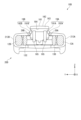
- FIG. 11 is a front view showing a plug according to a second embodiment.
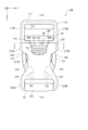
- FIG. 13 is a front view showing a buckle according to a third embodiment.
- FIG. 13 is a rear view showing the buckle according to the third embodiment.
- 12 is a cross-sectional view taken along line CC in FIG. 11 .
- 12 is a cross-sectional view taken along line DD in FIG. 11 .
- FIG. 11 is a front view showing a plug according to a third embodiment.
- FIG. 13 is a front view showing a socket according to a third embodiment.
- FIG. 14 is a diagram illustrating the operation of the buckle according to the third embodiment, and corresponds to FIG. 13 .
- FIG. 15 is a diagram illustrating the operation of the buckle according to the third embodiment, and corresponds to FIG. 14 .
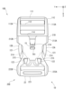
- FIG. 13 is a front view showing a buckle according to a fourth embodiment.
- FIG. 13 is a rear view showing the buckle according to the fourth embodiment.
- 20 is a cross-sectional view taken along line E-E of FIG. 19 .
- FIG. 13 is a rear view showing the plug according to the fourth embodiment.
- FIG. 22 is a diagram illustrating the operation of the buckle according to the fourth embodiment, and corresponds to FIG. 21 .
- FIG. 23 is a diagram illustrating the operation of the buckle according to the fourth embodiment, and corresponds to FIG. 22 .
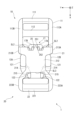
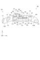
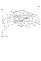
- the plug 10 includes an attachment portion 11 to which an adherend can be attached, a pair of legs 12A, 12B protruding in the X direction from the attachment portion 11 and elastically engaging with the socket 20, a pair of support legs 13A, 13B connected to the pair of legs 12A, 12B, and a switching portion 14 disposed between the pair of legs 12A, 12B and supported by the pair of support legs 13A, 13B.
- the plug 10 of this embodiment is integrally molded from, for example, a synthetic resin material.
- the mounting part 11 has rod parts 111, 112 arranged along the Y direction, and a pair of side walls 113A, 113B that connect the rod parts 111, 112 at both ends in the Y direction.
- the legs 12A and 12B are connected to the mounting part 11 at positions spaced apart from each other in the Y direction.
- the leg 12A is connected to the side wall 113A of the mounting part 11, and the leg 12B is connected to the side wall 113B.
- the legs 12A and 12B include a leg piece 121 extending from the mounting part 11 in the X direction, and a pair of protrusions 122 (see FIG. 3) protruding from the tip of the leg piece 121 in the Z direction or the -Z direction.
- the leg piece 121 is formed so as to be elastically deformable in the Y direction.
- the operation unit 16 is disposed on the -X side of the engagement unit 15, and has a convex shape that protrudes in the Z direction from the base 140.
- the operation unit 16 has an operation surface 161 that faces the +Z direction.
- the operation unit 16 is formed with a recess 162 that opens in each of the -Z and -X directions and communicates with a gap G between claws 17A and 17B, which will be described later.
- the base portion 140 and the operation portion 16 may have a lightening hole that opens in the -Z direction.
- the posture maintaining unit 17 is disposed on the -X side of the operating unit 16 and has a pair of claws 17A, 17B that face each other with a gap G between them in the Y direction.
- the gap G between the pair of claws 17A, 17B is connected to the recess 162 of the operating unit 16.
- These claws 17A, 17B are formed to be elastically deformable in the Z direction.
- the second wall portion 212 has a pair of slits SL2 cut into the second wall portion 212 in the +X direction from the first opening AP1, and a slit SL3 cut into the second wall portion 212 in the -X direction from the second opening AP2.
- the pair of slits SL2 prevent interference between the pair of claw portions 17A, 17B and the second wall portion 212 when the position of the switching portion 14 changes.
- the slits SL3 expose the protrusions 122 of the pair of legs 12A, 12B in the -Z direction from the case portion 21.
- the side walls 213A, 213B are portions that connect the first wall 211 and the second wall 212 to each other. As shown in FIG. 5, the side walls 213A, 213B have holes TH2 that penetrate the side walls 213A, 213B in the Y direction. Each hole TH2 exposes the leg pieces 121 of the legs 12A, 12B outward in the Y direction from the case 21. The parts of the leg pieces 121 that are exposed from the holes TH2 of the case 21 serve as operating parts for operating the legs 12A, 12B when the buckle 1 is released.
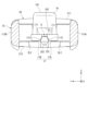
- the protrusions 122 of the legs 12A and 12B are pressed by the guide surface 214 of the socket 20, causing the leg pieces 121 of the legs 12A and 12B to elastically deform inward in the Y direction. Then, when the protrusions 122 climb over the guide surface 214, the pressure applied to the protrusions 122 from the guide surface 214 is released, and the shape of the leg pieces 121 returns to its original shape. This allows the protrusions 122 to engage with the engaged surface 215 of the socket 20 in the -X direction, as shown in FIG. 1. In other words, the legs 12A and 12B engage with the socket 20 in the X direction.
- the guide portion 24 When the plug 10 is inserted into the socket 20, the guide portion 24 is inserted into the recess 132 (see FIG. 6) in the connecting portion 131 of the support legs 13A and 13B, and guides the plug 10 in the X direction.
- the inclined surface 152 of the engaging portion 15 is pressed by the first wall portion 211 of the case portion 21, and the flexible portion 141 is elastically deformed.
- the engaging portion 15 reaches the hole TH1 of the first wall portion 211, the pressure applied to the engaging portion 15 from the first wall portion 211 is released, and the flexible portion 141 returns to its original shape. As a result, as shown in FIG.
- the engaging portion 15 is disposed in the hole TH1, and the abutment surface 151 of the engaging portion 15 can engage with the engaged portion 216, which is the edge of the hole TH1, in the -X direction. That is, the engaging portion 15 is in an "engaged state" in which it engages with the socket 20 in the X direction.
- the inclined surface 152 of the engagement portion 15 is pressed by the first wall portion 211 of the case portion 21, and the flexible portion 141 is elastically deformed, causing the attitude of the switching portion 14 to change slightly to the -Z side.
- the amount of movement of the claw portions 17A and 17B in the -Z direction due to the change in attitude of the switching portion 14 is smaller than the amount of movement required for the claw portions 17A and 17B to get over the stopper portion 25. Therefore, when the insertion of the plug 10 into the socket 20 is completed, the claw portions 17A and 17B are positioned on the +Z side of the stopper portion 25 without getting over the stopper portion 25 (see FIG. 4).
- the attitude maintaining portion 17 is in an "engagement maintaining state" in which the attitude of the switching portion 14 is maintained.
- the engaging portion 15 when the plug 10 is inserted into the socket 20, the engaging portion 15 enters the "engaged state” and the attitude maintaining portion 17 enters the "engaged state". While the attitude maintaining portion 17 is in the “engaged state”, the attitude maintaining portion 17 maintains the engaging portion 15 in the “engaged state” unless an operation is performed on the operating portion 16.
- the buckle 1 When the engaging portion 15 is in the "engaged state", the buckle 1 will not be released even if an unintentional pressure is applied to the pair of legs 12A, 12B. This improves the safety of the buckle 1.
- the user presses the operation unit 16 in the -Z direction, that is, applies pressure in the -Z direction to the operation surface 161 of the operation unit 16.
- the operation unit 16 receives pressure F in the -Z direction, and the flexible portion 141 elastically deforms, changing the attitude of the switching unit 14 to the -Z side.
- the stopper unit 25 when the stopper unit 25 is positioned within the recess 162 of the operating unit 16, the pressure applied from the stopper unit 25 to the claws 17A, 17B is released, and the claws 17A, 17B return to their original shapes.
- the claws 17A and 17B are positioned on the -Z side of the stopper portion 25, and the contact surfaces 171 of the claws 17A and 17B are able to contact the contacted surfaces 251 of the stopper portion 25.
- the attitude maintenance portion 17 goes into a "released maintenance state" in which the attitude of the switching portion 14 is maintained.
- the pair of legs 12A, 12B and the engaging portion 15 of the plug 10 can engage with the socket 20.
- the attitude of the switching portion 14 changes, and the engaging portion 15 switches from the engaged state to the released state.
- the attitude maintaining portion 17 maintains the attitude of the switching portion 14, so that the engaging portion 15 is maintained in the released state. Therefore, after releasing the pressure on the operating portion 16, the user can press the pair of legs 12A, 12B to release the plug 10 from the socket 20. That is, when releasing the plug 10 from the socket 20, the pair of legs 12A, 12B and the engaging portion 15 can be operated separately, not simultaneously. This improves the operability of the buckle 1, and the user can release the buckle 1 with one hand.
- the pair of claws 17A, 17B are connected to the operating unit 16 and are formed to be elastically deformable in the Z direction. With this configuration, the claws 17A, 17B that come into contact with the stopper portion 25 can be suitably moved in the Z direction, making it easier to switch the position of the switching unit 14.
- the posture maintaining portion 17 abuts against the socket 20 so as to maintain the posture of the switching portion 14 not only when the engaging portion 15 is in the released state, but also when the engaging portion 15 is in the engaged state. This allows the engaged state of the engaging portion 15 to be stably maintained.
- the engagement portion 15 is placed in the engagement position immediately after the plug 10 is inserted into the socket 20. In this configuration, there is no need to operate the operating portion 16 when connecting the plug 10 to the socket 20, making it easier to connect the buckle 1.
- the plug 10 further includes a pair of support legs 13A, 13B that extend from the base ends of the pair of legs 12A, 12B between the pair of legs 12A, 12B and the switching unit 14 and are connected to the switching unit 14. This configuration allows the switching unit 14 to be stably supported.
- the case portion 21 of the socket 20 has a pair of slits SL2 to avoid interference with the claw portions 17A, 17B.
- the operating portion 16 can be positioned further in the +X direction compared to a case portion 21 without the pair of slits SL2. This allows the entire buckle 1 to be configured compactly.
- the buckle of the second embodiment is a modified example of the buckle 1 of the first embodiment, and includes a plug 10B shown in Fig. 10 and the socket 20 of the first embodiment.
- the plug 10B of the second embodiment differs from the first embodiment in the configuration of the pair of support legs 18A, 18B.
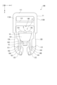
- the plug 10B includes an attachment portion 11, a pair of legs 12A, 12B, a pair of support legs 18A, 18B connected to the tips of the pair of legs 12A, 12B, and a switching portion 14B disposed between the pair of legs 12A, 12B and supported by the pair of support legs 18A, 18B.
- the support legs 18A and 18B extend in the ⁇ X direction from the tips of the legs 12A and 12B, passing between the engagement portion 15 and the legs 12A and 12B, and are connected to the operation portion 16, respectively. Further, the support legs 18A, 18B include a flexible portion 181 that is elastically deformable in the Z direction as a portion that is disposed on the +X side of the engagement portion 15. Specifically, the support legs 18A, 18B include the flexible portion 181 connected to each tip of the legs 12A, 12B, and a support leg main portion 182 that connects the flexible portion 181 and the operation unit 16.
- the switching unit 14B does not have the flexible portion 141 described in the first embodiment, and differs from the switching unit 14 of the first embodiment in that the operating unit 16 is supported by the support legs 18A and 18B.
- the buckle of the second embodiment described above can operate in the same manner as the buckle 1 of the first embodiment, and has the same effects as the buckle 1 of the first embodiment.
- the support legs 18A, 18B are connected to the operating unit 16 without passing between the operating unit 16 and the legs 12A, 12B, so a large space can be secured between the legs 12A, 12B in which the operating unit 16 is disposed.
- the Y-direction dimension of the operating unit 16 can be secured to be larger than in the first embodiment.
- a buckle 1C of the third embodiment includes a plug 10C and a socket 20C, similar to the buckle 1 of the first embodiment.
- the third embodiment differs from the first embodiment mainly in the configuration and operation of a switching unit 14C.
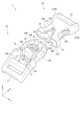
- the plug 10C includes an attachment portion 11C to which an object can be attached, a pair of legs 12A, 12B protruding in the X direction from the attachment portion 11C and elastically engaging with the socket 20C, a pair of support legs 13C, 13D connected to the attachment portion 11C, and a switching portion 14C disposed between the pair of legs 12A, 12B and supported by the pair of support legs 13C, 13D.
- the mounting portion 11C has rod portions 111, 112, and 114 arranged along the Y direction, and a pair of side walls 113A and 113B that connect the rod portions 111, 112, and 114 at both ends in the Y direction.
- the adherend is attached to the mounting portion 11C by wrapping the adherend around at least one of the rod portions 111 and 112.
- Support legs 13C, 13D are connected to attachment portion 11C on the inside in the Y direction relative to the pair of legs 12A, 12B. Specifically, support legs 13C, 13D extend from rod portion 114 in the +X direction while bending inward in the Y direction. The tips of support legs 13C, 13D form connecting portion 134 that connects them to each other. In addition, guide pieces 133 that extend in the +X direction while bending outward in the Y direction on the +X side of legs 12A, 12B are connected to the tips of support legs 13C, 13D.
- the base 140 and the engagement portion 15 may be configured in substantially the same manner as in the first embodiment.
- the base 140 connects the support legs 13C, 13D and the operation portion 16C.
- the base 140 also includes a flexible portion 141 that is elastically deformable in the Z direction as a portion located on the +X side of the engagement portion 15.
- the engagement portion 15 has a convex shape that protrudes from the base 140 in the +Z direction.
- the operation unit 16C has a plate portion 163 that is disposed on the -X side of the engagement unit 15 and in the Z direction of the base unit 140.
- This plate portion 163 has an operation surface 161 (first surface) that faces the +Z direction, and an operation surface 164 (second surface) that faces the +Z direction (see Figures 13 and 14).
- a gap GP is formed between the plate portion 163 and the rod portion 114 of the attachment portion 11, which allows the user's fingers or an instrument to reach the operation surface 164 from the +Z side of the buckle 1C.
- the operation surface 164 of the plate portion 163 may be provided with a reinforcing structure that protrudes in the -Z direction.
- the posture maintaining unit 19 has a pair of arms 19A, 19B provided at both ends of the plate unit 163 in the Y direction.
- the arm unit 19A has an arm main body unit 191A extending in the -Z direction from one end of the plate unit 163 in the Y direction, and a claw unit 192A protruding outward in the Y direction from the arm main body unit 191A.
- the arm unit 19B has an arm main body unit 191B extending in the -Z direction from the other end of the plate unit 163 in the Y direction, and a claw unit 192B protruding outward in the Y direction from the arm main body unit 191B.
- the arm main bodies 191A, 191B are formed to be elastically deformable in the Y direction.
- the socket 20C comprises a case portion 21C, an attachment portion 22 provided on the case portion 21 and capable of attaching an object to be attached, and a guide portion 24C and a stopper portion 26 provided on the case portion 21.
- Case portion 21C is configured in a manner similar to case portion 21 of the first embodiment. However, case portion 21C does not need to have slit SL2 of the first embodiment. Furthermore, socket 20C is preferably disposed along the edge of slit SL1 and includes wall portion 217 that protrudes from first wall portion 211 in the +Z direction. This wall portion 217 is disposed so as to surround operating portion 16C that is exposed in the +Z direction from case portion 21C. This allows stable operation of operating portion 16 and protects arms 19A, 19B from the outside.
- Guide portion 24C is provided in the center in the Y direction inside case portion 21C. Specifically, guide portion 24C has a guide protrusion 241 that is disposed along the X direction while protruding in the Z direction from the inner surface of second wall portion 212, and a guide end portion 242 that connects between first wall portion 211 and second wall portion 212 at the +X side end portion of guide protrusion portion 241 (see FIG. 13).
- the stopper portion 26 has a pair of stopper claws 26A, 26B arranged facing each other in the Y direction at the edge of the slit SL1 of the case portion 21.
- the stopper claws 26A, 26B protrude inward in the Y direction from the edge of the slit SL1, and the protruding height of each of the stopper claws 26A, 26B in the Y direction need only be such that they can interfere with the claws 192A, 192B.
- the user performs a first engagement operation by inserting the plug 10C into the first opening AP1 of the socket 20C. This causes the legs 12A and 12B to operate in the same manner as in the first embodiment and engage with the socket 20C in the X direction.
- the guide portion 24C is inserted between the support legs 13A and 13B, guides the plug 10 in the X direction, and then abuts against the plug 10 in the X direction.
- the claws 192A and 192B are positioned on the -Z side of the stopper claws 26A and 26B, and can abut against the stopper claws 26A and 26B in the +Z direction.
- the elasticity of the flexible portion 141 causes the attitude of the switching portion 14C to return to its original state.
- the claw portions 192A and 192B come into contact with the stopper claw portions 26A and 26B, restricting the movement of the switching portion 14C back to its original state.
- the attitude maintaining portion 19 goes into a "released maintaining state" in which the attitude of the switching portion 14C is maintained.
- the engaging section 15 When the attitude maintaining section 19 is in the "released state,” as shown in FIG. 17, the engaging section 15 is positioned on the -Z side of the engaged section 216. This causes the engaging section 15 to enter a "released state” in which it has released its engagement with the socket 20C in the X direction.
- the first engagement operation causes the legs 12A, 12B to engage with the socket 20C, but the engagement portion 15 goes into the "released state", and the posture maintaining portion 17 goes into the "released state".
- the engagement portion 15 is in the "released state”
- an elastic force is generated in the switching portion 14C, but because the posture maintaining portion 17 is in the "released state”, the engagement portion 15 is maintained in the "released state”.
- the posture maintaining portion 19 maintains the engagement portion 15 in the "released state” unless an operation is performed on the operating portion 16C.
- the user performs an operation of pulling up the operating portion 16C in the +Z direction, that is, an operation of applying pressure in the +Z direction to the operating surface 164.
- the attitude of the switching portion 14C changes to the +Z side so that the elastic deformation of the flexible portion 141 is released.
- the engaging portion 15 moves in the +Z direction.
- the engaging portion 15 is disposed within the hole TH1 of the first wall portion 211 and becomes able to engage with the engaged portion 216, which is the edge of the hole TH1, in the -X direction. That is, the engaging portion 15 is in an "engaged state” in which it can engage with the socket 20C in the X direction.
- the engaging portion 15 is in the "engaged state”
- the operating portion 16C is disposed in a state protruding further toward the +Z side than the case portion 21C as shown in Fig. 13. At this time, the engaging portion 15 is protected from external interference by the wall portion 217.
- the attitude maintaining unit 19 shown in Figures 17 and 18 moves in the +Z direction.
- the arm main bodies 191A, 191B elastically deform inward in the Y direction, and the claws 192A, 192B climb over the stopper claws 26A, 26B in the +Z direction.
- the claws 192A, 192B are positioned on the +Z side of the stopper claws 26A, 26B, and can abut against the stopper claws 26A, 26B in the -Z direction. This causes the attitude maintaining unit 19 to enter an "engagement maintaining state" in which the attitude of the switching unit 14 is maintained.
- the second engagement operation puts the engagement portion 15 in the “engaged state” and puts the attitude maintaining portion 19 in the “engaged state”. While the attitude maintaining portion 19 is in the “engaged state”, the attitude maintaining portion 19 maintains the engagement portion 15 in the “engaged state” unless an operation is performed on the operation portion 16C.
- the engaging portion 15 is in the "engaged state”
- the buckle 1C will not be released even if an unintentional pressure is applied to the pair of legs 12A, 12B, thereby improving the safety of the buckle 1C.
- the user performs an operation of applying pressure in the -Z direction to operation unit 16C.
- This switches engagement unit 15 from the “engaged state” to the “released state”, and also switches posture maintenance unit 19 from the “engaged state” to the “released state”.
- engagement unit 15 is in the "released state”
- an elastic force is generated in switching unit 14, but while posture maintenance unit 19 is in the "released state”
- engagement unit 15 is maintained in the "released state” even if pressure on operation unit 16C is released.
- the user applies pressure inward in the Y direction and in the -X direction to each leg piece 121 of legs 12A and 12B. This causes the plug 10 to be pulled out of the socket 20 in the -X direction.
- the buckle 1C of the present embodiment described above can achieve the same effect as the first embodiment. That is, in the buckle 1C of the present embodiment, as described above, when the engaging portion 15 is in an engaged state, the pair of legs 12A, 12B and the engaging portion 15 in the plug 10C can engage with the socket 20C. Also, when pressure is applied to the operating portion 16C, the attitude of the switching portion 14 changes, and the engaging portion 15 switches from the engaged state to the released state. At this time, the attitude maintaining portion 19 maintains the attitude of the switching portion 14C, so that the engaging portion 15 is maintained in the released state.
- the posture maintaining portion 17, 19 may abut against the socket 20, 20C, 20D when the engaging portion 15, 15D is in the released state, and may not abut against the socket 20, 20C, 20D when the engaging portion 15, 15D is in the engaged state.
- a gap in the Z direction may exist between the claw portions 17A, 17B and the stopper portion 25 (see FIG. 4).
- a gap in the Z direction may exist between the claw portions 192A, 192B and the stopper claw portions 26A, 26B (see FIG. 14, FIG. 22).
- the posture of the switching portion 14 may be maintained by the rigidity of the plug 10, 10B to 10D alone.
- the plugs 10, 10B of the first and second embodiments may be provided with an engagement portion 15D as described in the fourth embodiment, and the operating portion 16 of the first embodiment may be provided with an operating surface 164 as described in the third embodiment.
- the plugs 10C, 10D of the third and fourth embodiments may be provided with a pair of support legs 13C, 13D as described in the second embodiment.
- switching portion 140...base portion, 141...flexible portion, 15, 15D...engagement portion, 151...contact surface, 152...inclined surface, 16, 16C...operation portion, 161...operation surface (first surface), 162...recess, 163...plate portion, 164...operation surface (second surface), 165...support protrusion, 17...position maintaining portion, 17A, 17B...claw portion, 171...contact surface, 172...inclined surface, 18A, 18B...support leg portion, 19...position maintaining portion Holding part, 19A, 19B...Arm part, 191A, 191B...Arm body part, 192A, 192B...Claw part, 20, 20C, 20D...Socket, 21, 21C, 21D...Case part, 211, 21 1D...first wall part, 212, 212D...second wall part, 213A, 213B...side wall part, 214...guide surface, 215...engaged surface, 216...engaged part, 217...wall part, 22...attachment part, 2
Landscapes
- Buckles (AREA)
- Details Of Connecting Devices For Male And Female Coupling (AREA)
Abstract
Priority Applications (4)
| Application Number | Priority Date | Filing Date | Title |
|---|---|---|---|
| DE112023006815.1T DE112023006815T5 (de) | 2023-08-21 | 2023-08-21 | Schließe |
| CN202380101268.1A CN121666181A (zh) | 2023-08-21 | 2023-08-21 | 带扣 |
| JP2025541186A JPWO2025041229A1 (fr) | 2023-08-21 | 2023-08-21 | |
| PCT/JP2023/030014 WO2025041229A1 (fr) | 2023-08-21 | 2023-08-21 | Boucle |
Applications Claiming Priority (1)
| Application Number | Priority Date | Filing Date | Title |
|---|---|---|---|
| PCT/JP2023/030014 WO2025041229A1 (fr) | 2023-08-21 | 2023-08-21 | Boucle |
Publications (1)
| Publication Number | Publication Date |
|---|---|
| WO2025041229A1 true WO2025041229A1 (fr) | 2025-02-27 |
Family
ID=94731826
Family Applications (1)
| Application Number | Title | Priority Date | Filing Date |
|---|---|---|---|
| PCT/JP2023/030014 Ceased WO2025041229A1 (fr) | 2023-08-21 | 2023-08-21 | Boucle |
Country Status (4)
| Country | Link |
|---|---|
| JP (1) | JPWO2025041229A1 (fr) |
| CN (1) | CN121666181A (fr) |
| DE (1) | DE112023006815T5 (fr) |
| WO (1) | WO2025041229A1 (fr) |
Citations (4)
| Publication number | Priority date | Publication date | Assignee | Title |
|---|---|---|---|---|
| JPH0670805A (ja) * | 1992-08-27 | 1994-03-15 | Seiwa Shoji Kk | バックル |
| JPH07275012A (ja) * | 1994-04-05 | 1995-10-24 | Yoshio Tokuda | バックル |
| JPH11235208A (ja) * | 1998-02-20 | 1999-08-31 | Yoshio Tokuda | バックル |
| WO2022239062A1 (fr) * | 2021-05-10 | 2022-11-17 | Ykk株式会社 | Élément d'insertion mâle et boucle |
Family Cites Families (1)
| Publication number | Priority date | Publication date | Assignee | Title |
|---|---|---|---|---|
| US6311374B1 (en) | 2000-03-03 | 2001-11-06 | Joseph Anscher | High security buckle assembly |
-
2023
- 2023-08-21 DE DE112023006815.1T patent/DE112023006815T5/de active Pending
- 2023-08-21 JP JP2025541186A patent/JPWO2025041229A1/ja active Pending
- 2023-08-21 CN CN202380101268.1A patent/CN121666181A/zh active Pending
- 2023-08-21 WO PCT/JP2023/030014 patent/WO2025041229A1/fr not_active Ceased
Patent Citations (4)
| Publication number | Priority date | Publication date | Assignee | Title |
|---|---|---|---|---|
| JPH0670805A (ja) * | 1992-08-27 | 1994-03-15 | Seiwa Shoji Kk | バックル |
| JPH07275012A (ja) * | 1994-04-05 | 1995-10-24 | Yoshio Tokuda | バックル |
| JPH11235208A (ja) * | 1998-02-20 | 1999-08-31 | Yoshio Tokuda | バックル |
| WO2022239062A1 (fr) * | 2021-05-10 | 2022-11-17 | Ykk株式会社 | Élément d'insertion mâle et boucle |
Also Published As
| Publication number | Publication date |
|---|---|
| JPWO2025041229A1 (fr) | 2025-02-27 |
| DE112023006815T5 (de) | 2026-05-28 |
| CN121666181A (zh) | 2026-03-13 |
Similar Documents
| Publication | Publication Date | Title |
|---|---|---|
| EP2641498B1 (fr) | Boucle | |
| US5664961A (en) | Connector housing with lock | |
| TWI263478B (en) | Buckle | |
| JP3841389B2 (ja) | コネクタ嵌合構造 | |
| CN114080734B (zh) | 连接器 | |
| EP0327067B1 (fr) | Connecteur électrique avec couvercle ouvrant | |
| US11559113B2 (en) | Plug for buckle, and buckle | |
| JPH11149959A (ja) | コネクタ嵌合構造 | |
| JP4528642B2 (ja) | バックル | |
| US12616278B2 (en) | Plug and buckle | |
| JP6764883B2 (ja) | バックル | |
| WO2013121559A1 (fr) | Boucle | |
| TWI601345B (zh) | 可插拔連接器 | |
| KR200497693Y1 (ko) | 잠금쇠 및 잠금 해제 구조를 지닌 커넥터 | |
| US12331568B2 (en) | Vehicle door handle | |
| US7318739B2 (en) | Connector | |
| CN101227041B (zh) | 连接器的锁定机构 | |
| CN121666181A (zh) | 带扣 | |
| JPH07275012A (ja) | バックル | |
| JP2574527B2 (ja) | 光コネクタ | |
| JP5538074B2 (ja) | バックル | |
| KR20220002511U (ko) | 잠금쇠 및 잠금 해제 구조를 지닌 커넥터 | |
| WO2026105275A1 (fr) | Boucle | |
| WO2026069465A1 (fr) | Boucle | |
| JPH07155207A (ja) | バックル |
Legal Events
| Date | Code | Title | Description |
|---|---|---|---|
| 121 | Ep: the epo has been informed by wipo that ep was designated in this application |
Ref document number: 23949690 Country of ref document: EP Kind code of ref document: A1 |
|
| ENP | Entry into the national phase |
Ref document number: 2025541186 Country of ref document: JP Kind code of ref document: A |
|
| WWE | Wipo information: entry into national phase |
Ref document number: 2025541186 Country of ref document: JP |
|
| WWE | Wipo information: entry into national phase |
Ref document number: 112023006815 Country of ref document: DE |
|
| WWP | Wipo information: published in national office |
Ref document number: 112023006815 Country of ref document: DE |