WO2025041229A1 - Buckle - Google Patents
Buckle Download PDFInfo
- Publication number
- WO2025041229A1 WO2025041229A1 PCT/JP2023/030014 JP2023030014W WO2025041229A1 WO 2025041229 A1 WO2025041229 A1 WO 2025041229A1 JP 2023030014 W JP2023030014 W JP 2023030014W WO 2025041229 A1 WO2025041229 A1 WO 2025041229A1
- Authority
- WO
- WIPO (PCT)
- Prior art keywords
- pair
- socket
- legs
- plug
- buckle
- Prior art date
- Legal status (The legal status is an assumption and is not a legal conclusion. Google has not performed a legal analysis and makes no representation as to the accuracy of the status listed.)
- Ceased
Links
Images










Classifications
-
- A—HUMAN NECESSITIES
- A44—HABERDASHERY; JEWELLERY
- A44B—BUTTONS, PINS, BUCKLES, SLIDE FASTENERS, OR THE LIKE
- A44B11/00—Buckles; Similar fasteners for interconnecting straps or the like, e.g. for safety belts
- A44B11/25—Buckles; Similar fasteners for interconnecting straps or the like, e.g. for safety belts with two or more separable parts
- A44B11/26—Buckles; Similar fasteners for interconnecting straps or the like, e.g. for safety belts with two or more separable parts with push-button fastenings
- A44B11/266—Buckles; Similar fasteners for interconnecting straps or the like, e.g. for safety belts with two or more separable parts with push-button fastenings with at least one push-button acting parallel to the main plane of the buckle and perpendicularly to the direction of the fastening action
Definitions
- buckles equipped with a plug and socket are known as buckles that detachably connect two objects to be attached, and one such buckle is the buckle disclosed in Patent Document 1.
- the present invention aims to provide a buckle with improved operability.
- a buckle according to one embodiment of the present invention is a buckle comprising a plug and a socket into which the plug is inserted, wherein the plug comprises an attachment portion to which an object can be attached, a pair of legs that protrude from the attachment portion in the insertion direction into the socket and elastically engage with the socket, and a switching portion that is disposed between the pair of legs and is supported by the attachment portion or the pair of legs, wherein the switching portion comprises an engagement portion that switches between an engagement state in which it engages with the socket and a release state in which it releases the engagement with the socket depending on the attitude of the switching portion relative to the socket, an operating portion that receives pressure that changes the attitude of the switching portion relative to the socket, and a posture maintaining portion that abuts against the socket so as to maintain the attitude of the switching portion at least when the engagement portion is in the release state.
- the pair of legs and the engaging portion can be operated separately rather than simultaneously, improving the operability of the buckle.
- the socket is provided with an opening through which the pair of legs are inserted, and includes a case portion that houses the pair of legs, and a stopper portion that protrudes from the opening of the case portion along the insertion direction, and the posture maintaining portion may abut against the stopper portion in a thickness direction that intersects the insertion direction.
- the position maintaining portion and the stopper portion are disposed outside the case portion, it is easy to ensure the thickness of each of the position maintaining portion and the stopper portion, and the strength when they come into contact with each other can be improved.
- the posture maintaining portion has a pair of claw portions that face each other in a left-right direction that intersects both the insertion direction and the thickness direction, and abut against the stopper portion in the thickness direction.
- the pair of claws can stably maintain the position of the switching portion.
- the socket includes a case portion having an opening through which the pair of legs are inserted and which accommodates the pair of legs, a slit formed in the case portion so as to communicate with the opening and which exposes the operating portion from the case portion in a thickness direction intersecting the insertion direction, and a stopper portion provided on the edge of the slit, and the posture maintaining portion may abut against the stopper portion in the thickness direction.
- the position maintaining portion is disposed within the slit of the socket, it is easy to reduce the dimensions of the buckle.
- the stopper portion has a pair of stopper claw portions protruding inward in left-right directions intersecting the insertion direction and the thickness direction from the edges of the slit, and the posture maintaining portion has a pair of claw portions abutting the pair of stopper claw portions in the thickness direction.
- the pair of claws can stably maintain the position of the switching portion.
- the posture maintaining portion further includes an arm main body portion formed to be elastically deformable in the left-right direction, and the pair of claw portions are connected to the operating portion via the arm main body portion.
- the claw portion in contact with the stopper portion can be suitably moved in the thickness direction, making it easy to switch the position of the switching portion.
- the posture maintaining portion may abut against the socket so as to maintain the posture of the switching portion when the engagement portion is in the released state and when the engagement portion is in the engaged state. This makes it possible to stably maintain the engaged state of the engaging portion.
- the engaging portion may be placed in the engaged state immediately after the plug is inserted into the socket. In this configuration, since no operation of the operating portion is required when connecting the plug to the socket, the operation of connecting the buckle is facilitated.
- the engagement portion may be placed in the released state immediately after the plug is inserted into the socket.
- the plug can be pulled out from the socket immediately after the plug is connected to the socket, facilitating the operation of reconnecting the adherend.
- the plug may further include a pair of support legs passing from each base end of the pair of legs or the attachment portion between the pair of legs and the switching portion and connected to the switching portion. According to this configuration, the switching portion can be stably supported by the pair of support legs.
- the plug may further include a pair of support legs passing from each tip of the pair of legs between the pair of legs and the engagement portion and connected to the operating portion.
- the pair of support legs are connected to the operating part without passing between the operating part and the legs, so that a large space can be secured between the pair of legs in which the operating part is disposed, and as a result, a large width dimension of the operating part can be secured.
- the operating portion has a first surface facing one side in a thickness direction intersecting the insertion direction of the plug, and a second surface facing the other side in the thickness direction, and the engagement portion may be switched between the engaged state and the released state by pressure applied to the first surface or the second surface.
- the user can freely switch the engaging portion between the engaged state and the released state, which further improves the operability of the buckle.
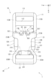
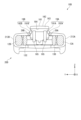
- FIG. 11 is a front view showing a plug according to a second embodiment.
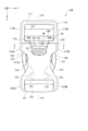
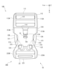
- FIG. 13 is a front view showing a buckle according to a third embodiment.
- FIG. 13 is a rear view showing the buckle according to the third embodiment.
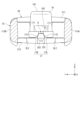
- 12 is a cross-sectional view taken along line CC in FIG. 11 .
- 12 is a cross-sectional view taken along line DD in FIG. 11 .
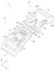
- FIG. 11 is a front view showing a plug according to a third embodiment.
- FIG. 13 is a front view showing a socket according to a third embodiment.
- FIG. 14 is a diagram illustrating the operation of the buckle according to the third embodiment, and corresponds to FIG. 13 .
- FIG. 15 is a diagram illustrating the operation of the buckle according to the third embodiment, and corresponds to FIG. 14 .
- FIG. 13 is a front view showing a buckle according to a fourth embodiment.
- FIG. 13 is a rear view showing the buckle according to the fourth embodiment.
- 20 is a cross-sectional view taken along line E-E of FIG. 19 .
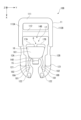
- FIG. 13 is a rear view showing the plug according to the fourth embodiment.
- FIG. 22 is a diagram illustrating the operation of the buckle according to the fourth embodiment, and corresponds to FIG. 21 .
- FIG. 23 is a diagram illustrating the operation of the buckle according to the fourth embodiment, and corresponds to FIG. 22 .
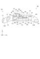
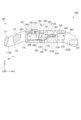
- the plug 10 includes an attachment portion 11 to which an adherend can be attached, a pair of legs 12A, 12B protruding in the X direction from the attachment portion 11 and elastically engaging with the socket 20, a pair of support legs 13A, 13B connected to the pair of legs 12A, 12B, and a switching portion 14 disposed between the pair of legs 12A, 12B and supported by the pair of support legs 13A, 13B.
- the plug 10 of this embodiment is integrally molded from, for example, a synthetic resin material.
- the mounting part 11 has rod parts 111, 112 arranged along the Y direction, and a pair of side walls 113A, 113B that connect the rod parts 111, 112 at both ends in the Y direction.
- the legs 12A and 12B are connected to the mounting part 11 at positions spaced apart from each other in the Y direction.
- the leg 12A is connected to the side wall 113A of the mounting part 11, and the leg 12B is connected to the side wall 113B.
- the legs 12A and 12B include a leg piece 121 extending from the mounting part 11 in the X direction, and a pair of protrusions 122 (see FIG. 3) protruding from the tip of the leg piece 121 in the Z direction or the -Z direction.
- the leg piece 121 is formed so as to be elastically deformable in the Y direction.
- the operation unit 16 is disposed on the -X side of the engagement unit 15, and has a convex shape that protrudes in the Z direction from the base 140.
- the operation unit 16 has an operation surface 161 that faces the +Z direction.
- the operation unit 16 is formed with a recess 162 that opens in each of the -Z and -X directions and communicates with a gap G between claws 17A and 17B, which will be described later.
- the base portion 140 and the operation portion 16 may have a lightening hole that opens in the -Z direction.
- the posture maintaining unit 17 is disposed on the -X side of the operating unit 16 and has a pair of claws 17A, 17B that face each other with a gap G between them in the Y direction.
- the gap G between the pair of claws 17A, 17B is connected to the recess 162 of the operating unit 16.
- These claws 17A, 17B are formed to be elastically deformable in the Z direction.
- the second wall portion 212 has a pair of slits SL2 cut into the second wall portion 212 in the +X direction from the first opening AP1, and a slit SL3 cut into the second wall portion 212 in the -X direction from the second opening AP2.
- the pair of slits SL2 prevent interference between the pair of claw portions 17A, 17B and the second wall portion 212 when the position of the switching portion 14 changes.
- the slits SL3 expose the protrusions 122 of the pair of legs 12A, 12B in the -Z direction from the case portion 21.
- the side walls 213A, 213B are portions that connect the first wall 211 and the second wall 212 to each other. As shown in FIG. 5, the side walls 213A, 213B have holes TH2 that penetrate the side walls 213A, 213B in the Y direction. Each hole TH2 exposes the leg pieces 121 of the legs 12A, 12B outward in the Y direction from the case 21. The parts of the leg pieces 121 that are exposed from the holes TH2 of the case 21 serve as operating parts for operating the legs 12A, 12B when the buckle 1 is released.
- the protrusions 122 of the legs 12A and 12B are pressed by the guide surface 214 of the socket 20, causing the leg pieces 121 of the legs 12A and 12B to elastically deform inward in the Y direction. Then, when the protrusions 122 climb over the guide surface 214, the pressure applied to the protrusions 122 from the guide surface 214 is released, and the shape of the leg pieces 121 returns to its original shape. This allows the protrusions 122 to engage with the engaged surface 215 of the socket 20 in the -X direction, as shown in FIG. 1. In other words, the legs 12A and 12B engage with the socket 20 in the X direction.
- the guide portion 24 When the plug 10 is inserted into the socket 20, the guide portion 24 is inserted into the recess 132 (see FIG. 6) in the connecting portion 131 of the support legs 13A and 13B, and guides the plug 10 in the X direction.
- the inclined surface 152 of the engaging portion 15 is pressed by the first wall portion 211 of the case portion 21, and the flexible portion 141 is elastically deformed.
- the engaging portion 15 reaches the hole TH1 of the first wall portion 211, the pressure applied to the engaging portion 15 from the first wall portion 211 is released, and the flexible portion 141 returns to its original shape. As a result, as shown in FIG.
- the engaging portion 15 is disposed in the hole TH1, and the abutment surface 151 of the engaging portion 15 can engage with the engaged portion 216, which is the edge of the hole TH1, in the -X direction. That is, the engaging portion 15 is in an "engaged state" in which it engages with the socket 20 in the X direction.
- the inclined surface 152 of the engagement portion 15 is pressed by the first wall portion 211 of the case portion 21, and the flexible portion 141 is elastically deformed, causing the attitude of the switching portion 14 to change slightly to the -Z side.
- the amount of movement of the claw portions 17A and 17B in the -Z direction due to the change in attitude of the switching portion 14 is smaller than the amount of movement required for the claw portions 17A and 17B to get over the stopper portion 25. Therefore, when the insertion of the plug 10 into the socket 20 is completed, the claw portions 17A and 17B are positioned on the +Z side of the stopper portion 25 without getting over the stopper portion 25 (see FIG. 4).
- the attitude maintaining portion 17 is in an "engagement maintaining state" in which the attitude of the switching portion 14 is maintained.
- the engaging portion 15 when the plug 10 is inserted into the socket 20, the engaging portion 15 enters the "engaged state” and the attitude maintaining portion 17 enters the "engaged state". While the attitude maintaining portion 17 is in the “engaged state”, the attitude maintaining portion 17 maintains the engaging portion 15 in the “engaged state” unless an operation is performed on the operating portion 16.
- the buckle 1 When the engaging portion 15 is in the "engaged state", the buckle 1 will not be released even if an unintentional pressure is applied to the pair of legs 12A, 12B. This improves the safety of the buckle 1.
- the user presses the operation unit 16 in the -Z direction, that is, applies pressure in the -Z direction to the operation surface 161 of the operation unit 16.
- the operation unit 16 receives pressure F in the -Z direction, and the flexible portion 141 elastically deforms, changing the attitude of the switching unit 14 to the -Z side.
- the stopper unit 25 when the stopper unit 25 is positioned within the recess 162 of the operating unit 16, the pressure applied from the stopper unit 25 to the claws 17A, 17B is released, and the claws 17A, 17B return to their original shapes.
- the claws 17A and 17B are positioned on the -Z side of the stopper portion 25, and the contact surfaces 171 of the claws 17A and 17B are able to contact the contacted surfaces 251 of the stopper portion 25.
- the attitude maintenance portion 17 goes into a "released maintenance state" in which the attitude of the switching portion 14 is maintained.
- the pair of legs 12A, 12B and the engaging portion 15 of the plug 10 can engage with the socket 20.
- the attitude of the switching portion 14 changes, and the engaging portion 15 switches from the engaged state to the released state.
- the attitude maintaining portion 17 maintains the attitude of the switching portion 14, so that the engaging portion 15 is maintained in the released state. Therefore, after releasing the pressure on the operating portion 16, the user can press the pair of legs 12A, 12B to release the plug 10 from the socket 20. That is, when releasing the plug 10 from the socket 20, the pair of legs 12A, 12B and the engaging portion 15 can be operated separately, not simultaneously. This improves the operability of the buckle 1, and the user can release the buckle 1 with one hand.
- the pair of claws 17A, 17B are connected to the operating unit 16 and are formed to be elastically deformable in the Z direction. With this configuration, the claws 17A, 17B that come into contact with the stopper portion 25 can be suitably moved in the Z direction, making it easier to switch the position of the switching unit 14.
- the posture maintaining portion 17 abuts against the socket 20 so as to maintain the posture of the switching portion 14 not only when the engaging portion 15 is in the released state, but also when the engaging portion 15 is in the engaged state. This allows the engaged state of the engaging portion 15 to be stably maintained.
- the engagement portion 15 is placed in the engagement position immediately after the plug 10 is inserted into the socket 20. In this configuration, there is no need to operate the operating portion 16 when connecting the plug 10 to the socket 20, making it easier to connect the buckle 1.
- the plug 10 further includes a pair of support legs 13A, 13B that extend from the base ends of the pair of legs 12A, 12B between the pair of legs 12A, 12B and the switching unit 14 and are connected to the switching unit 14. This configuration allows the switching unit 14 to be stably supported.
- the case portion 21 of the socket 20 has a pair of slits SL2 to avoid interference with the claw portions 17A, 17B.
- the operating portion 16 can be positioned further in the +X direction compared to a case portion 21 without the pair of slits SL2. This allows the entire buckle 1 to be configured compactly.
- the buckle of the second embodiment is a modified example of the buckle 1 of the first embodiment, and includes a plug 10B shown in Fig. 10 and the socket 20 of the first embodiment.
- the plug 10B of the second embodiment differs from the first embodiment in the configuration of the pair of support legs 18A, 18B.
- the plug 10B includes an attachment portion 11, a pair of legs 12A, 12B, a pair of support legs 18A, 18B connected to the tips of the pair of legs 12A, 12B, and a switching portion 14B disposed between the pair of legs 12A, 12B and supported by the pair of support legs 18A, 18B.
- the support legs 18A and 18B extend in the ⁇ X direction from the tips of the legs 12A and 12B, passing between the engagement portion 15 and the legs 12A and 12B, and are connected to the operation portion 16, respectively. Further, the support legs 18A, 18B include a flexible portion 181 that is elastically deformable in the Z direction as a portion that is disposed on the +X side of the engagement portion 15. Specifically, the support legs 18A, 18B include the flexible portion 181 connected to each tip of the legs 12A, 12B, and a support leg main portion 182 that connects the flexible portion 181 and the operation unit 16.
- the switching unit 14B does not have the flexible portion 141 described in the first embodiment, and differs from the switching unit 14 of the first embodiment in that the operating unit 16 is supported by the support legs 18A and 18B.
- the buckle of the second embodiment described above can operate in the same manner as the buckle 1 of the first embodiment, and has the same effects as the buckle 1 of the first embodiment.
- the support legs 18A, 18B are connected to the operating unit 16 without passing between the operating unit 16 and the legs 12A, 12B, so a large space can be secured between the legs 12A, 12B in which the operating unit 16 is disposed.
- the Y-direction dimension of the operating unit 16 can be secured to be larger than in the first embodiment.
- a buckle 1C of the third embodiment includes a plug 10C and a socket 20C, similar to the buckle 1 of the first embodiment.
- the third embodiment differs from the first embodiment mainly in the configuration and operation of a switching unit 14C.
- the plug 10C includes an attachment portion 11C to which an object can be attached, a pair of legs 12A, 12B protruding in the X direction from the attachment portion 11C and elastically engaging with the socket 20C, a pair of support legs 13C, 13D connected to the attachment portion 11C, and a switching portion 14C disposed between the pair of legs 12A, 12B and supported by the pair of support legs 13C, 13D.
- the mounting portion 11C has rod portions 111, 112, and 114 arranged along the Y direction, and a pair of side walls 113A and 113B that connect the rod portions 111, 112, and 114 at both ends in the Y direction.
- the adherend is attached to the mounting portion 11C by wrapping the adherend around at least one of the rod portions 111 and 112.
- Support legs 13C, 13D are connected to attachment portion 11C on the inside in the Y direction relative to the pair of legs 12A, 12B. Specifically, support legs 13C, 13D extend from rod portion 114 in the +X direction while bending inward in the Y direction. The tips of support legs 13C, 13D form connecting portion 134 that connects them to each other. In addition, guide pieces 133 that extend in the +X direction while bending outward in the Y direction on the +X side of legs 12A, 12B are connected to the tips of support legs 13C, 13D.
- the base 140 and the engagement portion 15 may be configured in substantially the same manner as in the first embodiment.
- the base 140 connects the support legs 13C, 13D and the operation portion 16C.
- the base 140 also includes a flexible portion 141 that is elastically deformable in the Z direction as a portion located on the +X side of the engagement portion 15.
- the engagement portion 15 has a convex shape that protrudes from the base 140 in the +Z direction.
- the operation unit 16C has a plate portion 163 that is disposed on the -X side of the engagement unit 15 and in the Z direction of the base unit 140.
- This plate portion 163 has an operation surface 161 (first surface) that faces the +Z direction, and an operation surface 164 (second surface) that faces the +Z direction (see Figures 13 and 14).
- a gap GP is formed between the plate portion 163 and the rod portion 114 of the attachment portion 11, which allows the user's fingers or an instrument to reach the operation surface 164 from the +Z side of the buckle 1C.
- the operation surface 164 of the plate portion 163 may be provided with a reinforcing structure that protrudes in the -Z direction.
- the posture maintaining unit 19 has a pair of arms 19A, 19B provided at both ends of the plate unit 163 in the Y direction.
- the arm unit 19A has an arm main body unit 191A extending in the -Z direction from one end of the plate unit 163 in the Y direction, and a claw unit 192A protruding outward in the Y direction from the arm main body unit 191A.
- the arm unit 19B has an arm main body unit 191B extending in the -Z direction from the other end of the plate unit 163 in the Y direction, and a claw unit 192B protruding outward in the Y direction from the arm main body unit 191B.
- the arm main bodies 191A, 191B are formed to be elastically deformable in the Y direction.
- the socket 20C comprises a case portion 21C, an attachment portion 22 provided on the case portion 21 and capable of attaching an object to be attached, and a guide portion 24C and a stopper portion 26 provided on the case portion 21.
- Case portion 21C is configured in a manner similar to case portion 21 of the first embodiment. However, case portion 21C does not need to have slit SL2 of the first embodiment. Furthermore, socket 20C is preferably disposed along the edge of slit SL1 and includes wall portion 217 that protrudes from first wall portion 211 in the +Z direction. This wall portion 217 is disposed so as to surround operating portion 16C that is exposed in the +Z direction from case portion 21C. This allows stable operation of operating portion 16 and protects arms 19A, 19B from the outside.
- Guide portion 24C is provided in the center in the Y direction inside case portion 21C. Specifically, guide portion 24C has a guide protrusion 241 that is disposed along the X direction while protruding in the Z direction from the inner surface of second wall portion 212, and a guide end portion 242 that connects between first wall portion 211 and second wall portion 212 at the +X side end portion of guide protrusion portion 241 (see FIG. 13).
- the stopper portion 26 has a pair of stopper claws 26A, 26B arranged facing each other in the Y direction at the edge of the slit SL1 of the case portion 21.
- the stopper claws 26A, 26B protrude inward in the Y direction from the edge of the slit SL1, and the protruding height of each of the stopper claws 26A, 26B in the Y direction need only be such that they can interfere with the claws 192A, 192B.
- the user performs a first engagement operation by inserting the plug 10C into the first opening AP1 of the socket 20C. This causes the legs 12A and 12B to operate in the same manner as in the first embodiment and engage with the socket 20C in the X direction.
- the guide portion 24C is inserted between the support legs 13A and 13B, guides the plug 10 in the X direction, and then abuts against the plug 10 in the X direction.
- the claws 192A and 192B are positioned on the -Z side of the stopper claws 26A and 26B, and can abut against the stopper claws 26A and 26B in the +Z direction.
- the elasticity of the flexible portion 141 causes the attitude of the switching portion 14C to return to its original state.
- the claw portions 192A and 192B come into contact with the stopper claw portions 26A and 26B, restricting the movement of the switching portion 14C back to its original state.
- the attitude maintaining portion 19 goes into a "released maintaining state" in which the attitude of the switching portion 14C is maintained.
- the engaging section 15 When the attitude maintaining section 19 is in the "released state,” as shown in FIG. 17, the engaging section 15 is positioned on the -Z side of the engaged section 216. This causes the engaging section 15 to enter a "released state” in which it has released its engagement with the socket 20C in the X direction.
- the first engagement operation causes the legs 12A, 12B to engage with the socket 20C, but the engagement portion 15 goes into the "released state", and the posture maintaining portion 17 goes into the "released state".
- the engagement portion 15 is in the "released state”
- an elastic force is generated in the switching portion 14C, but because the posture maintaining portion 17 is in the "released state”, the engagement portion 15 is maintained in the "released state”.
- the posture maintaining portion 19 maintains the engagement portion 15 in the "released state” unless an operation is performed on the operating portion 16C.
- the user performs an operation of pulling up the operating portion 16C in the +Z direction, that is, an operation of applying pressure in the +Z direction to the operating surface 164.
- the attitude of the switching portion 14C changes to the +Z side so that the elastic deformation of the flexible portion 141 is released.
- the engaging portion 15 moves in the +Z direction.
- the engaging portion 15 is disposed within the hole TH1 of the first wall portion 211 and becomes able to engage with the engaged portion 216, which is the edge of the hole TH1, in the -X direction. That is, the engaging portion 15 is in an "engaged state” in which it can engage with the socket 20C in the X direction.
- the engaging portion 15 is in the "engaged state”
- the operating portion 16C is disposed in a state protruding further toward the +Z side than the case portion 21C as shown in Fig. 13. At this time, the engaging portion 15 is protected from external interference by the wall portion 217.
- the attitude maintaining unit 19 shown in Figures 17 and 18 moves in the +Z direction.
- the arm main bodies 191A, 191B elastically deform inward in the Y direction, and the claws 192A, 192B climb over the stopper claws 26A, 26B in the +Z direction.
- the claws 192A, 192B are positioned on the +Z side of the stopper claws 26A, 26B, and can abut against the stopper claws 26A, 26B in the -Z direction. This causes the attitude maintaining unit 19 to enter an "engagement maintaining state" in which the attitude of the switching unit 14 is maintained.
- the second engagement operation puts the engagement portion 15 in the “engaged state” and puts the attitude maintaining portion 19 in the “engaged state”. While the attitude maintaining portion 19 is in the “engaged state”, the attitude maintaining portion 19 maintains the engagement portion 15 in the “engaged state” unless an operation is performed on the operation portion 16C.
- the engaging portion 15 is in the "engaged state”
- the buckle 1C will not be released even if an unintentional pressure is applied to the pair of legs 12A, 12B, thereby improving the safety of the buckle 1C.
- the user performs an operation of applying pressure in the -Z direction to operation unit 16C.
- This switches engagement unit 15 from the “engaged state” to the “released state”, and also switches posture maintenance unit 19 from the “engaged state” to the “released state”.
- engagement unit 15 is in the "released state”
- an elastic force is generated in switching unit 14, but while posture maintenance unit 19 is in the "released state”
- engagement unit 15 is maintained in the "released state” even if pressure on operation unit 16C is released.
- the user applies pressure inward in the Y direction and in the -X direction to each leg piece 121 of legs 12A and 12B. This causes the plug 10 to be pulled out of the socket 20 in the -X direction.
- the buckle 1C of the present embodiment described above can achieve the same effect as the first embodiment. That is, in the buckle 1C of the present embodiment, as described above, when the engaging portion 15 is in an engaged state, the pair of legs 12A, 12B and the engaging portion 15 in the plug 10C can engage with the socket 20C. Also, when pressure is applied to the operating portion 16C, the attitude of the switching portion 14 changes, and the engaging portion 15 switches from the engaged state to the released state. At this time, the attitude maintaining portion 19 maintains the attitude of the switching portion 14C, so that the engaging portion 15 is maintained in the released state.
- the posture maintaining portion 17, 19 may abut against the socket 20, 20C, 20D when the engaging portion 15, 15D is in the released state, and may not abut against the socket 20, 20C, 20D when the engaging portion 15, 15D is in the engaged state.
- a gap in the Z direction may exist between the claw portions 17A, 17B and the stopper portion 25 (see FIG. 4).
- a gap in the Z direction may exist between the claw portions 192A, 192B and the stopper claw portions 26A, 26B (see FIG. 14, FIG. 22).
- the posture of the switching portion 14 may be maintained by the rigidity of the plug 10, 10B to 10D alone.
- the plugs 10, 10B of the first and second embodiments may be provided with an engagement portion 15D as described in the fourth embodiment, and the operating portion 16 of the first embodiment may be provided with an operating surface 164 as described in the third embodiment.
- the plugs 10C, 10D of the third and fourth embodiments may be provided with a pair of support legs 13C, 13D as described in the second embodiment.
- switching portion 140...base portion, 141...flexible portion, 15, 15D...engagement portion, 151...contact surface, 152...inclined surface, 16, 16C...operation portion, 161...operation surface (first surface), 162...recess, 163...plate portion, 164...operation surface (second surface), 165...support protrusion, 17...position maintaining portion, 17A, 17B...claw portion, 171...contact surface, 172...inclined surface, 18A, 18B...support leg portion, 19...position maintaining portion Holding part, 19A, 19B...Arm part, 191A, 191B...Arm body part, 192A, 192B...Claw part, 20, 20C, 20D...Socket, 21, 21C, 21D...Case part, 211, 21 1D...first wall part, 212, 212D...second wall part, 213A, 213B...side wall part, 214...guide surface, 215...engaged surface, 216...engaged part, 217...wall part, 22...attachment part, 2
Landscapes
- Buckles (AREA)
- Details Of Connecting Devices For Male And Female Coupling (AREA)
Abstract
Description
本発明は、プラグおよびソケットを備えるバックルに関する。 The present invention relates to a buckle equipped with a plug and a socket.
従来、2つの被着体を着脱自在に連結するバックルとして、プラグおよびソケットを備えるバックルが知られており、このようなバックルの一種として、特許文献1に開示されるバックルが存在する。
Conventionally, buckles equipped with a plug and socket are known as buckles that detachably connect two objects to be attached, and one such buckle is the buckle disclosed in
特許文献1に開示されるバックルにおいて、プラグは、一対の脚部と、一対の脚部の間に配置された係合部(ボタン)とを備える。このようなバックルでは、プラグをソケットに差し込むと、一対の脚部および係合部のそれぞれがソケットに対して弾性的に係合することで、プラグがソケットに結合する。
In the buckle disclosed in
しかし、特許文献1のバックルでは、プラグをソケットから結合解除するためには、一対の脚部および係合部を同時に操作する必要がある。このため、片手による操作が困難であり、操作性が低いという問題がある。
However, with the buckle in
本発明は、操作性を向上させたバックルを提供することを目的とする。 The present invention aims to provide a buckle with improved operability.
(第1態様)
本発明の一態様に係るバックルは、プラグおよび前記プラグが差し込まれるソケットを備えるバックルであって、前記プラグは、被着体を取付可能な取付部と、前記取付部から前記ソケットに対する差込方向に突出し、かつ、前記ソケットに弾性的に係合する一対の脚部と、前記一対の脚部の間に配置され、かつ、前記取付部または前記一対の脚部に支持された切替部と、を備え、前記切替部は、前記ソケットに対する前記切替部の姿勢に応じて、前記ソケットと係合する係合状態と前記ソケットとの係合を解除する解除状態との間で切り替わる係合部と、前記ソケットに対する前記切替部の姿勢を変化させる押圧を受ける操作部と、少なくとも前記係合部が前記解除状態であるとき、前記切替部の姿勢を維持するように前記ソケットに当接する姿勢維持部と、を備える。
このような構成によれば、プラグをソケットから結合解除する際、一対の脚部および係合部を同時ではなく別々に操作することができるため、バックルの操作性が向上する。
(First aspect)
A buckle according to one embodiment of the present invention is a buckle comprising a plug and a socket into which the plug is inserted, wherein the plug comprises an attachment portion to which an object can be attached, a pair of legs that protrude from the attachment portion in the insertion direction into the socket and elastically engage with the socket, and a switching portion that is disposed between the pair of legs and is supported by the attachment portion or the pair of legs, wherein the switching portion comprises an engagement portion that switches between an engagement state in which it engages with the socket and a release state in which it releases the engagement with the socket depending on the attitude of the switching portion relative to the socket, an operating portion that receives pressure that changes the attitude of the switching portion relative to the socket, and a posture maintaining portion that abuts against the socket so as to maintain the attitude of the switching portion at least when the engagement portion is in the release state.
According to this configuration, when the plug is to be released from the socket, the pair of legs and the engaging portion can be operated separately rather than simultaneously, improving the operability of the buckle.
(第2態様)
本発明の第1態様に係るバックルにおいて、前記ソケットは、前記一対の脚部により挿通される開口部が設けられ、かつ、前記一対の脚部を収容するケース部と、前記ケース部の前記開口部から前記差込方向に沿って突出するストッパ部と、を備え、前記姿勢維持部は、前記ストッパ部に対して前記差込方向に交差する厚み方向に当接してもよい。
このような構成では、姿勢維持部およびストッパ部がケース部の外側に配置されるため、姿勢維持部およびストッパ部の各厚みを確保し易く、互いに当接する際の強度を向上できる。
(Second Aspect)
In the buckle of the first aspect of the present invention, the socket is provided with an opening through which the pair of legs are inserted, and includes a case portion that houses the pair of legs, and a stopper portion that protrudes from the opening of the case portion along the insertion direction, and the posture maintaining portion may abut against the stopper portion in a thickness direction that intersects the insertion direction.
In such a configuration, since the position maintaining portion and the stopper portion are disposed outside the case portion, it is easy to ensure the thickness of each of the position maintaining portion and the stopper portion, and the strength when they come into contact with each other can be improved.
(第3態様)
本発明の第2態様に係るバックルにおいて、前記姿勢維持部は、前記差込方向および前記厚み方向のそれぞれに交差する左右方向に互いに対向し、かつ、前記ストッパ部に対して前記厚み方向に当接する一対の爪部を備えることが好ましい。
このような構成では、一対の爪部により切替部の姿勢を安定的に維持することができる。
(Third aspect)
In the buckle of the second aspect of the present invention, it is preferable that the posture maintaining portion has a pair of claw portions that face each other in a left-right direction that intersects both the insertion direction and the thickness direction, and abut against the stopper portion in the thickness direction.
In this configuration, the pair of claws can stably maintain the position of the switching portion.
(第4態様)
本発明の第3態様に係るバックルにおいて、前記一対の爪部は、前記操作部に接続され、かつ、前記厚み方向に弾性変形可能に形成されていることが好ましい。
このような構成によれば、ストッパ部に当接した爪部が厚み方向に好適に移動可能になり、切替部の姿勢の切り替えが容易になる。
(Fourth aspect)
In the buckle according to the third aspect of the present invention, it is preferable that the pair of claw portions are connected to the operation portion and are formed to be elastically deformable in the thickness direction.
According to this configuration, the claw portion that comes into contact with the stopper portion can be suitably moved in the thickness direction, making it easy to switch the position of the switching portion.
(第5態様)
本発明の第1態様に係るバックルにおいて、前記ソケットは、前記一対の脚部により挿通される開口部が設けられ、かつ、前記一対の脚部を収容するケース部と、前記開口部に連通するように前記ケース部に形成され、前記ケース部から前記操作部を前記差込方向に交差する厚み方向に露出させるスリットと、前記スリットの縁に設けられたストッパ部と、を備え、前記姿勢維持部は、前記ストッパ部に対して前記厚み方向に当接してもよい。
このような構成では、姿勢維持部がソケットのスリット内に配置されるため、バックルの寸法を小型化することが容易である。
(Fifth aspect)
In the buckle of the first aspect of the present invention, the socket includes a case portion having an opening through which the pair of legs are inserted and which accommodates the pair of legs, a slit formed in the case portion so as to communicate with the opening and which exposes the operating portion from the case portion in a thickness direction intersecting the insertion direction, and a stopper portion provided on the edge of the slit, and the posture maintaining portion may abut against the stopper portion in the thickness direction.
In this configuration, since the position maintaining portion is disposed within the slit of the socket, it is easy to reduce the dimensions of the buckle.
(第6態様)
本発明の第5態様に係るバックルにおいて、前記ストッパ部は、前記スリットの縁から前記差込方向および前記厚み方向のそれぞれに交差する左右方向の内側に向かって突出する一対のストッパ爪部を備え、前記姿勢維持部は、前記一対のストッパ爪部に対して前記厚み方向に当接する一対の爪部を備えることが好ましい。
このような構成では、一対の爪部により切替部の姿勢を安定的に維持することができる。
(Sixth aspect)
In the buckle of the fifth aspect of the present invention, it is preferable that the stopper portion has a pair of stopper claw portions protruding inward in left-right directions intersecting the insertion direction and the thickness direction from the edges of the slit, and the posture maintaining portion has a pair of claw portions abutting the pair of stopper claw portions in the thickness direction.
In this configuration, the pair of claws can stably maintain the position of the switching portion.
(第7態様)
本発明の第6に係るバックルにおいて、前記姿勢維持部は、前記左右方向に弾性変形可能に形成された腕本体部をさらに備え、前記一対の爪部は、前記腕本体部を介して前記操作部に接続されていることが好ましい。
このような構成では、ストッパ爪部に当接したストッパ部に当接した爪部が厚み方向に好適に移動可能になり、切替部の姿勢の切り替えが容易になる。
(Seventh aspect)
In the buckle of the sixth aspect of the present invention, it is preferable that the posture maintaining portion further includes an arm main body portion formed to be elastically deformable in the left-right direction, and the pair of claw portions are connected to the operating portion via the arm main body portion.
In this configuration, the claw portion in contact with the stopper portion can be suitably moved in the thickness direction, making it easy to switch the position of the switching portion.
(第8態様)
本発明の第1~第7態様のいずれかに係るバックルにおいて、前記姿勢維持部は、前記係合部が前記解除状態であるとき、および、前記係合部が前記係合状態であるときのそれぞれで、前記切替部の姿勢を維持するように前記ソケットに当接してもよい。
これにより、係合部の係合状態を安定的に維持することができる。
(Eighth aspect)
In the buckle according to any of the first to seventh aspects of the present invention, the posture maintaining portion may abut against the socket so as to maintain the posture of the switching portion when the engagement portion is in the released state and when the engagement portion is in the engaged state.
This makes it possible to stably maintain the engaged state of the engaging portion.
(第9態様)
本発明の第1~第8態様のいずれかに係るバックルにおいて、前記係合部は、前記プラグが前記ソケットに差し込まれた直後、前記係合状態に配置されてもよい。
このような構成では、プラグをソケットに結合する際に操作部の操作を必要としないため、バックルの結合操作が容易になる。
(Ninth aspect)
In the buckle according to any one of the first to eighth aspects of the present invention, the engaging portion may be placed in the engaged state immediately after the plug is inserted into the socket.
In this configuration, since no operation of the operating portion is required when connecting the plug to the socket, the operation of connecting the buckle is facilitated.
(第10態様)
本発明の第1~第8態様のいずれかに係るバックルにおいて、前記係合部は、前記プラグが前記ソケットに差し込まれた直後、前記解除状態に配置されてもよい。
このような構成では、プラグをソケットに結合した後すぐに、プラグをソケットから引き抜くことができ、被着体を連結し直す操作が容易である。
(Tenth aspect)
In the buckle according to any one of the first to eighth aspects of the present invention, the engagement portion may be placed in the released state immediately after the plug is inserted into the socket.
In such a configuration, the plug can be pulled out from the socket immediately after the plug is connected to the socket, facilitating the operation of reconnecting the adherend.
(第11態様)
本発明の第1~第10態様のいずれかに係るバックルにおいて、前記プラグは、前記一対の脚部の各基端部または前記取付部から前記一対の脚部と前記切替部との間を通り、かつ、前記切替部に接続される一対の支持脚部をさらに備えてもよい。
このような構成によれば、一対の支持脚部により切替部を安定的に支持することができる。
(Eleventh aspect)
In the buckle according to any one of the first to tenth aspects of the present invention, the plug may further include a pair of support legs passing from each base end of the pair of legs or the attachment portion between the pair of legs and the switching portion and connected to the switching portion.
According to this configuration, the switching portion can be stably supported by the pair of support legs.
(第12態様)
本発明の第1~第10態様のいずれかに係るバックルにおいて、前記プラグは、前記一対の脚部の各先端部から前記一対の脚部と前記係合部との間を通り、かつ、前記操作部に接続される一対の支持脚部をさらに備えてもよい。
このような構成によれば、一対の支持脚部は、操作部と脚部との間を通らずに操作部に接続されるため、一対の脚部の間において操作部が配置される空間を大きく確保できる。その結果、操作部の幅寸法を大きく確保できる。
(Twelfth aspect)
In the buckle according to any one of the first to tenth aspects of the present invention, the plug may further include a pair of support legs passing from each tip of the pair of legs between the pair of legs and the engagement portion and connected to the operating portion.
According to this configuration, the pair of support legs are connected to the operating part without passing between the operating part and the legs, so that a large space can be secured between the pair of legs in which the operating part is disposed, and as a result, a large width dimension of the operating part can be secured.
(第13態様)
本発明の第1~第12態様のいずれかに係るバックルにおいて、前記操作部は、前記プラグの前記差込方向に交差する厚み方向の一方側に面する第1面と、前記厚み方向の他方側に面する第2面とを有し、前記係合部は、前記第1面または前記第2面に加わる押圧により、前記係合状態と前記解除状態との間で切り替わってもよい。
このような構成において、使用者は、係合部を係合状態および解除状態のそれぞれに自由に切り替えることができる。このため、バックルの操作性がより向上する。
(Thirteenth aspect)
In the buckle according to any one of the first to twelfth aspects of the present invention, the operating portion has a first surface facing one side in a thickness direction intersecting the insertion direction of the plug, and a second surface facing the other side in the thickness direction, and the engagement portion may be switched between the engaged state and the released state by pressure applied to the first surface or the second surface.
In this configuration, the user can freely switch the engaging portion between the engaged state and the released state, which further improves the operability of the buckle.
(第14態様)
本発明の第13態様に係るバックルにおいて、前記係合部は、前記第1面に加わる押圧により、前記解除状態から前記係合状態に切り替わり、前記切替部は、前記操作部の前記第2面から突出し、前記ソケットの内面に当接可能な支持凸部を有してもよい。
このような構成では、使用者による操作部の押し込み量が大きい場合など、支持凸部がソケットの内面に当接する。これにより、可撓部が過剰に変形することが防止され、プラグの破損が抑制される。
(14th aspect)
In the buckle of the thirteenth aspect of the present invention, the engagement portion is switched from the released state to the engaged state by pressure applied to the first surface, and the switching portion may have a support protrusion protruding from the second surface of the operating portion and capable of abutting against an inner surface of the socket.
In this configuration, when the user presses the operation portion to a great extent, the support protrusion comes into contact with the inner surface of the socket, thereby preventing the flexible portion from being excessively deformed and suppressing damage to the plug.
以下、本発明の複数の実施形態について図面に基づき説明する。なお、第2実施形態以降では、第1実施形態と同様の構成について、第1実施形態と同様の符号を付し、説明を省略または簡略化する。 Below, several embodiments of the present invention will be described with reference to the drawings. Note that in the second and subsequent embodiments, the same components as in the first embodiment will be denoted by the same reference numerals as in the first embodiment, and descriptions thereof will be omitted or simplified.
[第1実施形態]
本発明の第1実施形態について図1~図9を参照して説明する。
図1~図5に示すように、本実施形態のバックル1は、プラグ10と、プラグ10が差し込まれるソケット20とを備える。プラグ10およびソケット20のそれぞれには、被着体が取り付けられ、ソケット20に対してプラグ10が結合することにより、2つの被着体同士が連結される。なお、被着体としては、ベルト、テープまたは紐など、任意の長尺物が挙げられる。
[First embodiment]
A first embodiment of the present invention will be described with reference to FIGS.
1 to 5, the
以下の説明では、ソケット20およびプラグ10の長さ方向をX方向とし、バックル1の幅方向(左右方向)をY方向とし、バックル1の厚み方向(上下方向)をZ方向とする。X方向、Y方向およびZ方向は、互いに直交する。また、X方向のうち、ソケット20に対するプラグ10の差込方向を+X方向とし、プラグ10の差込方向とは反対方向(すなわち抜去方向)を-X方向とする。また、Z方向のうち、バックル1の裏面から表面に向かう方向を+Z方向とし、バックル1の表面から裏面に向かう方向を-Z方向とする。Y方向については、バックル1のY方向中心に向かう方向をY方向内側と称し、バックル1のY方向中心から離間する方向をY方向外側と称する。
In the following description, the length direction of the
(プラグ10の構成)
プラグ10は、図6に示すように、被着体を取付可能な取付部11と、取付部11からX方向に突出しかつソケット20に弾性的に係合する一対の脚部12A,12Bと、一対の脚部12A,12Bに接続された一対の支持脚部13A,13Bと、一対の脚部12A,12Bの間に配置されかつ一対の支持脚部13A,13Bに支持された切替部14とを備える。なお、本実施形態のプラグ10は、例えば合成樹脂材料により一体的に成形されている。
(Configuration of plug 10)
6, the
取付部11は、Y方向に沿って配置された棒部111,112と、棒部111,112同士をY方向の両端部で連結する一対の側壁部113A,113Bとを有する。棒部111,112同士の間には、被着体が挿通する隙間が存在しており、棒部111,112の少なくとも一方に被着体が巻き付けられることで、取付部11に被着体が取り付けられる。
The mounting
脚部12A,12Bは、取付部11においてY方向に互いに離間した位置に接続されている。具体的には、脚部12Aは、取付部11の側壁部113Aに接続され、脚部12Bは、側壁部113Bに接続されている。また、脚部12A,12Bは、取付部11からX方向に沿って延びた脚片部121と、脚片部121の先端部からZ方向または-Z方向に突出した一対の突起部122(図3参照)と、を備える。脚片部121は、Y方向に弾性変形可能に形成されている。
The
支持脚部13A,13Bは、脚部12A,12Bの基端部に接続され、脚部12A,12Bの各基端部から一対の脚部12A,12Bと切替部14との間を通るように延びている。具体的には、支持脚部13Aは、脚部12Aの基端部から+X方向に延びつつY方向内側に向かって屈曲している。同様に、支持脚部13Bは、脚部12Bの基端部から+X方向に延びつつY方向内側に向かって屈曲している。
支持脚部13A,13Bの各先端部は、互いに連結されることで連結部131を形成している。この連結部131には、-Z方向に開口しつつX方向に沿って延びる凹部132が形成されている。
The
The tip portions of the
切替部14は、一対の脚部12A,12Bの間(および一対の支持脚部13A,13Bの間)に配置され、支持脚部13A,13Bの連結部131により片持ち支持されている。具体的には、切替部14は、連結部131に接続された基部140と、基部140に設けられた係合部15と、基部140に接続された操作部16と、操作部16に接続された姿勢維持部17と、を備える。
The switching
基部140は、支持脚部13A,13Bと操作部16との間を連結する。また、基部140は、係合部15よりも+X側に配置される部分として、Z方向に弾性変形可能な可撓部141を含む。可撓部141の厚みは、基部140における他の部分の厚みよりも薄く形成されている。
本実施形態では、基部140の可撓部141が弾性変形することで、切替部14の姿勢が変化可能である。
The
In this embodiment, the
係合部15は、基部140から+Z方向に突出した凸形状を有する。また、図3に示すように、係合部15は、-X方向に面する当接面151と、+X方向に面しかつX方向およびZ方向に対して傾斜した傾斜面152とを有する。
The engaging
操作部16は、係合部15よりも-X側に配置され、かつ、基部140よりもZ方向に突出した凸形状を有する。この操作部16は、+Z方向に面した操作面161を有する。また、図4および図5に示すように、操作部16には、-Z方向および-X方向のそれぞれに開口し、かつ、後述の爪部17A,17Bの間の隙間Gに連通する凹部162が形成されている。
なお、基部140や操作部16は、-Z方向に開口する肉抜き孔を有してもよい。
The
The
姿勢維持部17は、操作部16よりも-X側に配置され、かつ、互いの間にY方向の隙間Gを介して対向する一対の爪部17A,17Bを備える。一対の爪部17A,17Bの間の隙間Gは、操作部16の凹部162に連通している。これら爪部17A,17Bは、Z方向に弾性変形可能に形成されている。
The
また、爪部17A,17Bは、図4に示すように、+Z方向に面する当接面171と、-Z方向に面する傾斜面172とを有する。爪部17A,17Bの各傾斜面172は、+Z方向に向かうほど一対の爪部17A,17Bの間の隙間Gが小さくなるように、Y方向およびZ方向に対して傾斜している。一対の爪部17A,17Bの間の隙間Gの最小寸法は、後述するストッパ部25のY方向の最大寸法よりも小さい。
As shown in FIG. 4, the
(ソケット20の構成)
ソケット20は、図7に示すように、ケース部21と、ケース部21に設けられ、被着体を取付可能な取付部22と、ケース部21に設けられたガイド部24およびストッパ部25とを備える。なお、本実施形態のソケット20は、例えば合成樹脂材料により一体的に成形されている。
(Configuration of socket 20)
7, the
ケース部21は、X方向に沿って配置される筒状に形成され、プラグ10の脚部12A,12Bを収容可能である(図1、図2参照)。具体的には、ケース部21は、Z方向に対向配置された第1壁部211および第2壁部212と、Y方向に対向配置された一対の側壁部213A,213Bとを備える。
The
また、ケース部21には、図3に示すように、-X方向に開口する第1開口部AP1と、+X方向に開口する第2開口部AP2とが形成されている。第1開口部AP1および第2開口部AP2のそれぞれは、ケース部21内の収容空間SPに連通している。また、第1開口部AP1は、一対の脚部12A,12Bが挿通する本発明の開口部に相当する。
Furthermore, as shown in FIG. 3, the
第1壁部211は、図1に示すように、第1開口部AP1から+X方向に第1壁部211を切り込んだ形状のスリットSL1を有する。このスリットSL1は、操作部16をケース部21から+Z方向に露出させる。また、第1壁部211は、スリットSL1に対する+X側に配置され、かつ、第1壁部211をZ方向に貫通している孔TH1を有する。この孔TH1は、係合部15をケース部21から+Z方向に露出させる。ここで、第1壁部211における孔TH1の-X側の縁部は、係合部15が係合するための被係合部216となる。
As shown in FIG. 1, the
第2壁部212は、図2に示すように、第1開口部AP1から+X方向に第2壁部212を切り込んだ形状の一対のスリットSL2と、第2開口部AP2から-X方向に第2壁部212を切り込んだ形状のスリットSL3とを有する。一対のスリットSL2は、切替部14の姿勢が変化する際、一対の爪部17A,17Bと第2壁部212とが干渉することを回避させる。スリットSL3は、一対の脚部12A,12Bの各突起部122をケース部21から-Z方向に露出させる。
2, the
側壁部213A,213Bは、第1壁部211および第2壁部212を互いに連結する部位である。側壁部213A,213Bは、図5に示すように、側壁部213A,213BをY方向に貫通する孔TH2を有する。各孔TH2は、脚部12A,12Bの脚片部121をケース部21からY方向外側に露出させる。なお、脚片部121のうち、ケース部21の孔TH2から露出する部分は、バックル1の結合解除時に脚部12A,12Bを操作するための操作部となる。
The
また、側壁部213A,213Bは、図1および図2に示すように、ケース部21内で-X方向に面するガイド面214と、ガイド面214に連続しかつ+X方向に面する一対の被係合面215とを有する。ガイド面214は、ソケット20に挿入される脚部12A,12Bの突起部122をX方向かつY方向内側に案内する。一対の被係合面215は、図示は省略するが、互いの間にZ方向の隙間を挟んで配置される。ガイド面214に案内された突起部122は、被係合面215に対してX方向に係合可能である。
As shown in Figures 1 and 2, the
取付部22は、Y方向に沿って配置された棒部221と、棒部221とケース部21との間を連結する一対の連結部223A,223Bとを有する。棒部221とケース部21との間には、被着体が挿通する隙間が存在しており、棒部221に被着体が巻き付けられることで、取付部22に被着体が取り付けられる。
The mounting
ガイド部24は、ケース部21内のY方向中央部において、第2壁部212から+Z方向に突出しつつX方向に沿って配置された突条である。
ストッパ部25は、ガイド部24から連続して形成されており、第2壁部212から+Z方向に突出しつつケース部21の第1開口部AP1から-X方向に突出している。このストッパ部25は、図4に示すように、-Z方向に面する被当接面251を有する。なお、ストッパ部25には、ストッパ部25の強度を増すために、被当接面251から-Z方向に突出する凸部252が設けられてもよい。
The
The
(バックル1の結合)
バックル1の結合動作について図1、図3および図4を参照して説明する。なお、使用者は、バックル1を結合させる場合、プラグ10をソケット20の第1開口部AP1に対して差し込む操作を行う。
(
The coupling operation of the
プラグ10がソケット20に差し込まれる際、脚部12A,12Bの各突起部122がソケット20のガイド面214から押圧を受けることで、脚部12A,12Bの各脚片部121がY方向内側に弾性変形する。そして、突起部122がガイド面214を乗り越えると、ガイド面214から突起部122に加わる押圧が解除され、脚片部121の形状が元に戻る。これにより、図1に示すように、突起部122がソケット20の被係合面215に対して-X方向に係合可能になる。すなわち、脚部12A,12Bは、ソケット20とX方向に係合する。
When the
また、プラグ10がソケット20に差し込まれる際、ガイド部24は、支持脚部13A,13Bの連結部131における凹部132(図6参照)に挿入され、プラグ10をX方向に案内する。また、係合部15の傾斜面152がケース部21の第1壁部211から押圧を受けることで、可撓部141が弾性変形する。そして、係合部15が第1壁部211の孔TH1に到達すると、第1壁部211から係合部15に加わる押圧が解除され、可撓部141が元の形状に戻る。これにより、図3に示すように、係合部15が孔TH1内に配置され、係合部15の当接面151が孔TH1の縁部である被係合部216に対して-X方向に係合可能になる。すなわち、係合部15は、ソケット20とX方向に係合する「係合状態」となる。
When the
また、プラグ10がソケット20に差し込まれる際、係合部15の傾斜面152がケース部21の第1壁部211から押圧を受け、可撓部141が弾性変形することで、切替部14の姿勢が-Z側に若干変化する。このとき、切替部14の姿勢変化に伴う爪部17A,17Bの-Z方向への移動量は、爪部17A,17Bがストッパ部25を乗り越えるために必要な移動量に比べて小さい。このため、ソケット20へのプラグ10の差し込みが完了したとき、爪部17A,17Bは、ストッパ部25を乗り越えることなく、ストッパ部25に対する+Z側に配置される(図4参照)。このとき、爪部17A,17Bの傾斜面172は、ストッパ部25に対して-Z方向に当接可能である。これにより、姿勢維持部17は、切替部14の姿勢を維持する「係合維持状態」となる。
When the
したがって、本実施形態では、プラグ10がソケット20に差し込まれると、係合部15が「係合状態」になると共に、姿勢維持部17が「係合維持状態」となる。姿勢維持部17が「係合維持状態」である間、操作部16に対する操作が行われない限り、姿勢維持部17は係合部15を「係合状態」に維持する。
なお、係合部15が「係合状態」である場合、一対の脚部12A,12Bに意図しない押圧が加わったとしても、バックル1は解除されない。これにより、バックル1の安全性を向上できる。
Therefore, in this embodiment, when the
When the engaging
(バックル1の結合解除)
バックル1の結合解除動作について、図8および図9を参照して説明する。なお、使用者は、バックル1を結合解除する場合、次に説明する第1解除操作および第2解除操作を順に行う。
(Uncoupling buckle 1)
The operation of releasing the
使用者は、第1解除操作として、操作部16を-Z方向に押し込む操作、すなわち、操作部16の操作面161に対して-Z方向の押圧を加える操作を行う。このとき、操作部16が-Z方向の押圧Fを受け、可撓部141が弾性変形することで、切替部14の姿勢が-Z側に変化する。
As a first release operation, the user presses the
切替部14の姿勢が-Z側に変化すると、係合部15が-Z方向に移動し、被係合部216よりも-Z側に配置される。これにより、係合部15は、ソケット20との係合を解除した「解除状態」になる。
When the position of the switching
また、切替部14の姿勢が-Z側に変化するとき、図4に示す姿勢維持部17が-Z方向に移動する。このとき、爪部17A,17Bの各傾斜面172がストッパ部25から押圧を受けることで、一対の爪部17A,17Bの間の隙間GがY方向に広がるように爪部17A,17Bが弾性変形する。ストッパ部25は、各傾斜面172に案内されることで一対の爪部17A,17Bの間の隙間Gを通過する。そして、ストッパ部25が操作部16の凹部162内に配置されると、ストッパ部25から爪部17A,17Bに加わる押圧が解除され、爪部17A,17Bが元の形状に戻る。これにより、図9に示すように、爪部17A,17Bは、ストッパ部25に対する-Z側に配置され、爪部17A,17Bの当接面171は、ストッパ部25の被当接面251に当接可能になる。
In addition, when the attitude of the switching
その後、操作面161に対する押圧Fが解除されると、可撓部141の弾性により、切替部14の姿勢が元の状態に戻ろうとする。しかし、爪部17A,17Bの当接面171がストッパ部25の被当接面251に当接することにより、切替部14の姿勢が元の状態に戻る動きは規制される。すなわち、姿勢維持部17は、切替部14の姿勢を維持する「解除維持状態」となる。
After that, when the pressure F on the
したがって、本実施形態では、第1解除操作により、係合部15が「解除状態」になると共に、姿勢維持部17が「解除維持状態」となる。係合部15が「解除状態」であるとき、切替部14に弾性力が生じた状態であるが、姿勢維持部17が「解除維持状態」であるため、操作部16に対する押圧が解除されても、係合部15は「解除状態」に維持される。すなわち、姿勢維持部17が「解除維持状態」である間、操作部16に対する操作が行われない限り、姿勢維持部17は係合部15を「解除状態」に維持する。
Therefore, in this embodiment, the first release operation puts the
次に、使用者は、第2解除操作として、脚部12A,12Bの各脚片部121に対してY方向内側および-X方向に向かう押圧を加える操作を行う。このとき、脚部12A,12Bの各脚片部121がY方向内側に弾性変形することで、脚部12A,12Bの各突起部122がソケット20の被係合面215から解除される。そして、プラグ10は、ソケット20から-X方向に引き抜かれる。
Next, as a second release operation, the user applies pressure inward in the Y direction and in the -X direction to each
以上の第1解除操作および第2解除操作によりバックル1の結合が解除される。ここで、第1解除操作および第2解除操作は、順に行われればよく、同時に行われる必要はない。
The above first and second release operations release the connection of the
(第1実施形態の効果)
本実施形態のバックル1では、上述したように、係合部15が係合状態であるとき、プラグ10における一対の脚部12A,12Bおよび係合部15のそれぞれがソケット20に係合できる。また、操作部16に押圧が加わると、切替部14の姿勢が変化し、係合部15が係合状態から解除状態に切り替わる。このとき、姿勢維持部17が切替部14の姿勢を維持するため、係合部15は解除状態に維持される。よって、使用者は、操作部16に対する押圧を解除した後、一対の脚部12A,12Bを押圧することで、プラグ10をソケット20から結合解除できる。すなわち、プラグ10をソケット20から結合解除する際、一対の脚部12A,12Bおよび係合部15を同時ではなく別々に操作することができる。これにより、バックル1の操作性が向上し、使用者がバックル1を片手で解除させることができる。
(Effects of the First Embodiment)
In the
本実施形態において、ソケット20は、ケース部21の第1開口部AP1からX方向に沿って突出するストッパ部25を備え、姿勢維持部17は、ストッパ部25に対してZ方向に当接する。このような構成では、姿勢維持部17およびストッパ部25がケース部21の外側に配置されるため、姿勢維持部17およびストッパ部25の各厚みを確保し易く、互いに当接する際の強度を向上できる。
In this embodiment, the
本実施形態において、姿勢維持部17は、ストッパ部25に対してZ方向に当接する一対の爪部17A,17Bを備える。このような構成では、一対の爪部17A,17Bにより切替部14の姿勢を安定的に維持することができる。
In this embodiment, the
本実施形態において、一対の爪部17A,17Bは、操作部16に接続され、かつ、Z方向に弾性変形可能に形成されている。このような構成によれば、ストッパ部25に当接した爪部17A,17BがZ方向に好適に移動可能になり、切替部14の姿勢の切り替えが容易になる。
In this embodiment, the pair of
本実施形態において、姿勢維持部17は、係合部15が解除状態であるときだけでなく、係合部15が係合状態であるときにおいても、切替部14の姿勢を維持するようにソケット20に当接する。これにより、係合部15の係合状態を安定的に維持することができる。
In this embodiment, the
本実施形態において、係合部15は、プラグ10がソケット20に差し込まれた直後、係合位置に配置される。このような構成では、プラグ10をソケット20に結合する際に操作部16の操作を必要としないため、バックル1の結合操作が容易になる。
In this embodiment, the
本実施形態において、プラグ10は、一対の脚部12A,12Bの各基端部から一対の脚部12A,12Bと切替部14との間を通るように延び、かつ、切替部14に接続される一対の支持脚部13A,13Bをさらに備える。このような構成によれば、切替部14を安定的に支持することができる。
In this embodiment, the
本実施形態において、ソケット20のケース部21は、爪部17A,17Bとの干渉を回避するための一対のスリットSL2を有する。このような構成によれば、ケース部21に一対のスリットSL2がない場合と比較して、操作部16をより+X方向側に配置させることができる。これにより、バックル1の全体をコンパクトに構成できる。また、爪部17A,17Bにケース部21の一対のスリットSL2内に配置されることで、爪部17A,17Bに対して過度な外力が加わることを防止でき、その結果、爪部17A,17Bの破壊を防止できる。
In this embodiment, the
[第2実施形態]
本発明の第2実施形態について、図10を参照して説明する。
第2実施形態のバックルは、第1実施形態のバックル1の変形例であり、図10に示すプラグ10Bと、第1実施形態のソケット20とを備える。第2実施形態のプラグ10Bは、一対の支持脚部18A,18Bに関する構成が第1実施形態と異なる。
[Second embodiment]
A second embodiment of the present invention will be described with reference to FIG.
The buckle of the second embodiment is a modified example of the
具体的には、プラグ10Bは、取付部11と、一対の脚部12A,12Bと、一対の脚部12A,12Bの先端部に接続された一対の支持脚部18A,18Bと、一対の脚部12A,12Bの間に配置されかつ一対の支持脚部18A,18Bに支持された切替部14Bと、を備える。
Specifically, the
支持脚部18A,18Bは、脚部12A,12Bの先端部から-X方向に延びつつ係合部15と脚部12A,12Bとの間を通り、操作部16に対してそれぞれ接続されている。
また、支持脚部18A,18Bは、係合部15よりも+X側に配置される部分として、Z方向に弾性変形可能な可撓部181を含む。具体的には、支持脚部18A,18Bは、脚部12A,12Bの各先端部に接続された可撓部181と、可撓部181と操作部16との間を連結する支持脚本体部182とを備える。
The
Further, the
切替部14Bは、第1実施形態で説明した可撓部141を備えず、操作部16が支持脚部18A,18Bに支持されている点で第1実施形態の切替部14とは異なる。
The
以上に説明した第2実施形態のバックルは、第1実施形態のバックル1と同様に動作可能であり、第1実施形態のバックル1と同様の効果を奏する。
The buckle of the second embodiment described above can operate in the same manner as the
また、第2実施形態のプラグ10Bにおいて、支持脚部18A,18Bは、操作部16と脚部12A,12Bとの間を通らずに操作部16に接続されるため、脚部12A,12B同士の間において操作部16が配置される空間を大きく確保できる。その結果、操作部16のY方向寸法を第1実施形態と比べて大きく確保することができる。
In addition, in the
[第3実施形態]
本発明の第3実施形態について、図11~図18を参照して説明する。
図11~図14に示すように、第3実施形態のバックル1Cは、第1実施形態のバックル1と同様、プラグ10Cおよびソケット20Cを備える。ただし、第3実施形態では、主に切替部14Cに関する構成やその動作が第1実施形態とは異なる。
[Third embodiment]
A third embodiment of the present invention will be described with reference to FIGS.
11 to 14, a
(プラグ10Cの構成)
プラグ10Cは、図15に示すように、被着体を取付可能な取付部11Cと、取付部11CからX方向に突出しかつソケット20Cに弾性的に係合する一対の脚部12A,12Bと、取付部11Cに接続された一対の支持脚部13C,13Dと、一対の脚部12A,12Bの間に配置されかつ一対の支持脚部13C,13Dに支持された切替部14Cとを備える。
(Configuration of
As shown in FIG. 15, the
取付部11Cは、Y方向に沿って配置された棒部111,112,114と、棒部111,112,114同士をY方向の両端部で連結する一対の側壁部113A,113Bとを有する。棒部111,112の少なくとも一方に被着体が巻き付けられることで、取付部11Cに被着体が取り付けられる。
The mounting
支持脚部13C,13Dは、一対の脚部12A,12Bに対するY方向内側で取付部11Cに接続されている。具体的には、支持脚部13C,13Dは、棒部114から+X方向に延びつつY方向内側に屈曲している。支持脚部13C,13Dの先端部は、互いに連結される連結部134を形成している。また、支持脚部13C,13Dの各先端部には、+X方向に延びつつ脚部12A,12Bよりも+X側でY方向外側に屈曲しているガイド片133が接続されている。
切替部14Cは、一対の脚部12A,12Bの間に配置され、かつ、支持脚部13C,13Dの連結部134により片持ち支持されている。具体的には、切替部14Cは、連結部134に接続された基部140と、基部140に設けられた係合部15と、基部140に接続された操作部16Cと、操作部16Cに接続された姿勢維持部19と、を備える。
The
基部140および係合部15は、第1実施形態とほぼ同様に構成されればよい。例えば、基部140は、支持脚部13C,13Dと操作部16Cとの間を連結する。また、基部140は、係合部15よりも+X側に配置される部分として、Z方向に弾性変形可能な可撓部141を含む。係合部15は、基部140から+Z方向に突出した凸形状を有する。
The
操作部16Cは、係合部15よりも-X側に配置され、かつ、基部140よりもZ方向に配置されたプレート部163を備える。このプレート部163は、+Z方向に面する操作面161(第1面)と、+Z方向に面する操作面164(第2面)とを有する(図13、図14参照)。
The
なお、図11に示すように、プレート部163と取付部11の棒部114との間には、使用者の手指または器具等がバックル1Cの+Z側から操作面164に到達することを可能にする隙間GPが形成されている。また、図14に示すように、プレート部163の操作面164には、-Z方向に突出する補強構造が設けられてもよい。
As shown in FIG. 11, a gap GP is formed between the
姿勢維持部19は、図15に示すように、プレート部163のY方向両端部に設けられた一対の腕部19A,19Bを備える。図14に示すように、腕部19Aは、プレート部163のY方向一方側の端部から-Z方向に延びる腕本体部191Aと、腕本体部191AからY方向外側に突出する爪部192Aとを有する。同様に、腕部19Bは、プレート部163のY方向他方側の端部から-Z方向に延びる腕本体部191Bと、腕本体部191BからY方向外側に突出する爪部192Bとを有する。腕本体部191A,191Bは、Y方向に弾性変形可能に形成されている。
As shown in FIG. 15, the
(ソケット20Cの構成)
ソケット20Cは、図16に示すように、ケース部21Cと、ケース部21に設けられ、被着体を取付可能な取付部22と、ケース部21に設けられたガイド部24Cおよびストッパ部26と、を備える。
(Configuration of
As shown in FIG. 16, the
ケース部21Cは、第1実施形態のケース部21とほぼ同様に構成される。ただし、ケース部21Cには、第1実施形態のスリットSL2が形成されなくてもよい。また、ソケット20Cは、スリットSL1の縁に沿って配置され、かつ、第1壁部211から+Z方向に突出する壁部217を備えることが好ましい。この壁部217は、ケース部21Cから+Z方向に露出する操作部16Cを囲うように配置される。これにより、操作部16を安定的に操作可能であるとともに、腕部19A,19Bを外部から保護することができる。
ガイド部24Cは、ケース部21C内のY方向中央部に設けられる。具体的には、ガイド部24Cは、第2壁部212の内面からZ方向に突出しつつX方向に沿って配置されるガイド凸部241と、ガイド凸部241の+X側端部において第1壁部211と第2壁部212との間を連結するガイド端部242とを有する(図13参照)。
ストッパ部26は、ケース部21のスリットSL1の縁部において、Y方向に互いに対向するように配置された一対のストッパ爪部26A,26Bを備える。ストッパ爪部26A,26Bは、スリットSL1の縁部からY方向内側に突出しており、Y方向におけるストッパ爪部26A,26Bの各突出高さは、爪部192A,192Bに干渉可能な程度であればよい。
The
(バックル1Cの結合;第1係合操作)
バックル1Cの結合動作について、図11、図13および図14を参照して説明する。なお、使用者は、バックル1Cを結合させる場合、次に説明する第1係合操作および第2係合操作を順に行う。
(Engagement of
The coupling operation of the
使用者は、第1係合操作として、プラグ10Cをソケット20Cの第1開口部AP1に対して差し込む操作を行う。これにより、脚部12A,12Bは、第1実施形態と同様に動作し、ソケット20CとX方向に係合する。なお、プラグ10Cがソケット20Cに差し込まれる際、ガイド部24Cは、支持脚部13A,13B同士の間に挿入され、プラグ10をX方向に案内した後、プラグ10に対してX方向に当接する。
The user performs a first engagement operation by inserting the
また、プラグ10Cがソケット20Cに差し込まれる際、係合部15がケース部21の第1壁部211から押圧を受け、可撓部141が弾性変形することで、切替部14Cの姿勢が-Z側に変化する。このとき、切替部14の姿勢変化に伴う爪部192A,192Bの-Z方向への移動量は、爪部192A,192Bがストッパ爪部26A,26Bを乗り越えるために必要な移動量よりも大きい。このため、姿勢維持部19では、腕本体部191A,191BがY方向内側に弾性変形すると共に、爪部192A,192Bがストッパ爪部26A,26Bを-Z方向に乗り越える。その結果、図17および図18に示すように、爪部192A,192Bは、ストッパ爪部26A,26Bに対する-Z側に配置され、ストッパ爪部26A,26Bに+Z方向に当接可能になる。
In addition, when
その後、可撓部141の弾性により切替部14Cの姿勢が元の状態に戻ろうとする。しかし、爪部192A,192Bがストッパ爪部26A,26Bに当接することにより、切替部14Cの姿勢が元の状態に戻る動きは規制される。すなわち、姿勢維持部19は、切替部14Cの姿勢を維持する「解除維持状態」となる。
Then, the elasticity of the
姿勢維持部19が「解除維持状態」であるとき、図17に示すように、係合部15は、被係合部216よりも-Z側に位置する。これにより、係合部15は、ソケット20CとのX方向の係合を解除した「解除状態」となる。
When the
したがって、本実施形態では、第1係合操作により、脚部12A,12Bがソケット20Cと係合するが、係合部15が「解除状態」になると共に、姿勢維持部17が「解除維持状態」となる。係合部15が「解除状態」であるとき、切替部14Cに弾性力が生じた状態であるが、姿勢維持部17が「解除維持状態」であるため、係合部15は「解除状態」に維持される。すなわち、姿勢維持部19が「解除維持状態」である間、操作部16Cに対する操作が行われない限り、姿勢維持部19は係合部15を「解除状態」に維持する。
Therefore, in this embodiment, the first engagement operation causes the
(バックル1Cの結合;第2係合操作)
使用者は、第1係合操作の後、必要に応じて、第2係合操作を行う。なお、使用者は、バックル1Cの使用場面に応じて、脚部12A,12Bがソケット20Cに係合していれば十分であると判断した場合、以降の第2係合操作を行わなくてもよい。
(Engagement of
After the first engagement operation, the user performs the second engagement operation as necessary. Note that if the user determines that it is sufficient for the
使用者は、第2係合操作として、操作部16Cを+Z方向に引き上げる操作、すなわち、操作面164に対して+Z方向の押圧を加える操作を行う。このとき、可撓部141の弾性変形が解消されるように、切替部14Cの姿勢が+Z側に変化する。
As a second engagement operation, the user performs an operation of pulling up the operating
切替部14Cの姿勢が+Z側に変化すると、係合部15が+Z方向に移動する。これにより、図13および図14に示すように、係合部15が第1壁部211の孔TH1内に配置され、孔TH1の縁部である被係合部216に対して-X方向に係合可能になる。すなわち、係合部15は、ソケット20CとX方向に係合可能な「係合状態」となる。
なお、係合部15が「係合状態」であるとき、図13に示すように、操作部16Cがケース部21Cよりも+Z側に突出した状態に配置される。このとき、係合部15は、壁部217により外部干渉から保護される。
When the attitude of the switching
When the engaging
また、切替部14Cの姿勢が+Z側に変化すると、図17および図18に示す姿勢維持部19が+Z方向に移動する。このとき、腕本体部191A,191BがY方向内側に弾性変形すると共に、爪部192A,192Bがストッパ爪部26A,26Bを+Z方向に乗り越える。その結果、図13および図14に示すように、爪部192A,192Bは、ストッパ爪部26A,26Bに対する+Z側に配置され、ストッパ爪部26A,26Bに-Z方向に当接可能になる。これにより、姿勢維持部19は、切替部14の姿勢を維持する「係合維持状態」となる。
Furthermore, when the attitude of the
したがって、本実施形態では、第2係合操作により、係合部15が「係合状態」になると共に、姿勢維持部19が「係合維持状態」となる。姿勢維持部19が「係合維持状態」である間、操作部16Cに対する操作が行われない限り、姿勢維持部19は係合部15を「係合状態」に維持する。
なお、係合部15が「係合状態」である場合、一対の脚部12A,12Bに意図しない押圧が加わったとしても、バックル1Cは解除されない。これにより、バックル1Cの安全性を向上できる。
Therefore, in this embodiment, the second engagement operation puts the
When the engaging
(バックル1Cの結合解除)
本実施形態において、バックル1Cの結合を解除する場合、使用者は、第1実施形態で説明した第1解除操作および第2解除操作と同様の操作を行えばよい。
(Uncoupling
In this embodiment, when releasing the connection of the
例えば、使用者は、第1解除操作として、操作部16Cに対して-Z方向の押圧を加える操作を行う。これにより、係合部15が「係合状態」から「解除状態」に切り替わると共に、姿勢維持部19が「係合維持状態」から「解除維持状態」に切り替わる。係合部15が「解除状態」であるとき、切替部14に弾性力が生じた状態であるが、姿勢維持部19が「解除維持状態」である間、操作部16Cに対する押圧が解除されても、係合部15は「解除状態」に維持される。
For example, as a first release operation, the user performs an operation of applying pressure in the -Z direction to
その後、使用者は、第2解除操作として、脚部12A,12Bの各脚片部121に対してY方向内側および-X方向に向かう押圧を加える操作を行う。これにより、プラグ10は、ソケット20から-X方向に引き抜かれる。
Then, as a second release operation, the user applies pressure inward in the Y direction and in the -X direction to each
以上の第1解除操作および第2解除操作によりバックル1Cの結合が解除される。ここで、第1解除操作および第2解除操作は、順に行われればよく、同時に行われる必要はない。
The above first and second release operations release the connection of the
(第3実施形態の効果)
以上の本実施形態のバックル1Cは、第1実施形態と同様の効果を奏することができる。すなわち、本実施形態のバックル1Cでは、上述したように、係合部15が係合状態であるとき、プラグ10Cにおける一対の脚部12A,12Bおよび係合部15のそれぞれがソケット20Cに係合できる。また、操作部16Cに押圧が加わると、切替部14の姿勢が変化し、係合部15が係合状態から解除状態に切り替わる。このとき、姿勢維持部19が切替部14Cの姿勢を維持するため、係合部15は解除状態に維持される。よって、使用者は、操作部16Cに対する押圧を解除した後、一対の脚部12A,12Bを押圧することで、プラグ10Cをソケット20Cから結合解除できる。すなわち、プラグ10Cをソケット20Cから結合解除する際、一対の脚部12A,12Bおよび係合部15を同時ではなく別々に操作することができる。これにより、バックル1Cの操作性が向上し、使用者がバックル1Cを片手で解除させることができする。
(Effects of the Third Embodiment)
The
第3実施形態のソケット20Cは、スリットSL1の縁に設けられたストッパ部26を備え、姿勢維持部19は、ストッパ部26に対してZ方向に当接することで、切替部14Cの姿勢を維持する。このような構成では、姿勢維持部19がソケット20のスリットSL1内に配置されるため、第1実施形態と比べてバックル1CのX方向の寸法を小型化することが容易である。
The
第3実施形態において、ストッパ部26は、スリットSL1の縁からY方向内側に突出する一対のストッパ爪部26A,26Bを備え、姿勢維持部19は、一対のストッパ爪部26A,26Bに対してZ方向に当接する一対の爪部192A,192Bを備える。このような構成では、一対の爪部192A,192Bにより切替部14Cの姿勢を安定的に維持することができる。
In the third embodiment, the
本実施形態において、姿勢維持部19は、Y方向に弾性変形可能に形成された腕本体部191A,191Bをさらに備え、一対の爪部192A,192Bは、腕本体部191A,191Bを介して操作部16Cに接続されている。このような構成では、ストッパ爪部26A,26Bに当接した爪部192A,192BがZ方向に好適に移動可能になり、切替部14Cの姿勢の切り替えが容易になる。
In this embodiment, the
第3実施形態において、係合部15は、プラグ10Cがソケット20Cに差し込まれた直後、解除位置に位置する。このような構成では、プラグ10Cをソケット20Cに結合した後すぐに、プラグ10Cをソケット20Cから引き抜くことができ、被着体を連結し直す操作が容易である。
In the third embodiment, the
第3実施形態において、操作部16Cは、+Z方向に面する操作面161と、-Z方向に面する操作面164とを有し、係合部15は、操作面161,164に加わる押圧により、係合状態と解除状態との間で切り替わる。このような構成において、使用者は、係合部15を係合状態および解除状態のそれぞれに自由に切り替えることができる。このため、バックル1Cの操作性がより向上する。
In the third embodiment, the
[第4実施形態]
本発明の第4実施形態について、図19~図25を参照して説明する。
図19~図22に示すように、第4実施形態のバックル1Dは、第3実施形態のバックル1Cの変形例であり、第3実施形態のバックル1Cと同様、プラグ10Dおよびソケット20Dを備える。ただし、第4実施形態では、プラグ10Dにおける係合部15Dの配置およびソケット20DにおけるスリットSL1の配置が第3実施形態とは異なる。
[Fourth embodiment]
A fourth embodiment of the present invention will be described with reference to FIGS.
19 to 22, the
具体的には、図21に示すように、切替部14Dは、第3実施形態の切替部14Cとほぼ同様の構成を有するが、係合部15の替わりとなる係合部15Dを備える。係合部15Dは、基部140に設けられ、基部140から-Z方向に突出した凸形状を有する。
Specifically, as shown in FIG. 21, the
ケース部21Dは、第3実施形態のケース部21Cとほぼ同様の構成を有するが、第1壁部211Dではなく、第2壁部212DをZ方向に貫通する孔TH1を有する。第2壁部212Dの孔TH1は、スリットSL1よりも+X側に配置され、係合部15Dをケース部21から-Z方向に露出させる。ここで、第2壁部212Dにおける孔TH1の-X側の縁部は、係合部15Dが係合するための被係合部216となる。
また、切替部14Dは、図23に示すように、操作部16Cの操作面164から-Z方向に突出した一対の支持凸部165をさらに備える。係合部15Dが係合状態であるとき、図21に示すように、支持凸部165は、ソケット20Dの内面、すなわち第2壁部212Dの内面にZ方向に当接可能である。
The
(バックル1Dの動作)
バックル1Dの結合動作および解除動作は、Z方向の向きが反対である以外、第3実施形態とほぼ同様である。以下、簡単に説明する。
(
The fastening and unfastening operations of the
使用者は、第1係合操作として、プラグ10Dをソケット20Dの第1開口部AP1に対して差し込む操作を行う。これにより、脚部12A,12Bは、第1実施形態と同様に動作し、ソケット20CとX方向に係合する。
The user performs a first engagement operation by inserting the
また、プラグ10Dがソケット20Dに差し込まれる際、係合部15の傾斜面152がソケット20Dの第2壁部212Dから押圧を受け、可撓部141が弾性変形することで、切替部14Dの姿勢が+Z側に変化する。その結果、図24および図25に示すように、爪部192A,192Bは、ストッパ爪部26A,26Bに対する+Z側に配置され、ストッパ爪部26A,26Bに-Z方向に当接可能になる。これにより、切替部14Dの姿勢が元の状態に戻る動きは規制される。すなわち、姿勢維持部19は、切替部14Dの姿勢を維持する「解除維持状態」となる。
In addition, when
また、姿勢維持部19が「解除維持状態」であるとき、係合部15Dは、被係合部216よりも+Z側に位置する。これにより、係合部15Dは、ソケット20DとのX方向の係合を解除した「解除状態」となる。
When the
使用者は、第2係合操作として、操作部16Cを-Z方向に押し込む操作、すなわち、操作部16Cの操作面161に対して-Z方向の押圧を加える操作を行う。このとき、可撓部141の弾性変形が解消されるように、切替部14Cの姿勢が-Z側に変化する。
その結果、図21および図22に示すように、係合部15Dが第2壁部212の孔TH1内に配置され、孔TH1の縁部である被係合部216に対して-X方向に係合可能になる。すなわち、係合部15Dは、ソケット20DとX方向に係合可能な「係合状態」となる。
また、爪部192A,192Bは、ストッパ爪部26A,26Bに対する-Z側に配置され、ストッパ爪部26A,26Bに+Z方向に当接可能になる。これにより、姿勢維持部19は、切替部14の姿勢を維持する「係合維持状態」となる。
As the second engagement operation, the user performs an operation of pushing the
21 and 22, the engaging
Furthermore, the
したがって、第4実施形態では、第3実施形態と同様、第1係合操作により脚部12A,12Bがソケット20Dと係合し、第2係合操作により係合部15Dがソケット20Dと係合する。
なお、第2係合操作時、使用者による操作部16Cの押し込み量が大きい場合など、支持凸部165が第2壁部212Dの内面に当接する。これにより、可撓部141が過剰に変形することが防止され、プラグ10Dの破損が抑制される。
Therefore, in the fourth embodiment, similarly to the third embodiment, the
During the second engagement operation, for example, when the user presses the
バックル1Dの結合を解除する場合、使用者は、第1実施形態で説明した第1解除操作および第2解除操作と同様の操作を行えばよい。なお、第4実施形態において、第1解除操作におけるZ方向の向きは、第1実施形態と反対である。
When releasing the
以上に説明した第4実施形態のバックル1Dは、第3実施形態のバックル1Cと同様の効果を奏する。
The
[変形例]
上記各実施形態では、各要素の好ましい形状について説明しているが、本発明はこれに限定されず、任意に変更可能である。
[Modification]
In each of the above embodiments, a preferred shape of each element has been described, but the present invention is not limited to this and can be modified as desired.
上記各実施形態において、脚部12A,12Bの具体的構成は、ソケット20,20C,20Dに係合可能であれば、特に限定されない。
例えば、上記第1実施形態において、脚部12A,12Bは、脚片部121の先端部から突出した突起部122を有するが、脚片部121の中間部から突出した突起部を有してもよい。この場合、脚部12A,12Bの突起部は、ソケット20の孔TH2から外側に露出しつつ、ソケット20に対してX方向に係合してもよい。このような変形例は、他の実施形態でも同様に適用される。
In each of the above embodiments, the specific configuration of the
For example, in the first embodiment described above, the
上記各実施形態において、プラグ10,10B,10C,10Dは、切替部14,14B,14C,14Dの姿勢を変化させるようにZ方向に弾性変形する可撓部141を有している。ここで、上記各実施形態の可撓部141は、切替部14,14B,14C,14Dの一部として構成されているが、本発明はこれに限られず、プラグ10,10B,10C,10Dにおける他の任意の部位が可撓部であってもよい。すなわち、切替部14,14B,14C,14Dが可撓部141を有することは必須ではない。
例えば、上記第1実施形態では、支持脚部13A,13Bのそれぞれの少なくとも一部が可撓部としてZ方向に弾性変形することで、切替部14の姿勢が変化してもよい。このような変形例は、他の実施形態でも同様に適用される。
In each of the above embodiments, the
For example, in the first embodiment, at least a part of each of the
上記各実施形態において、姿勢維持部17,19は、係合部15,15Dが解除状態であるときソケット20,20C,20Dに当接すればよく、係合部15,15Dが係合状態であるときソケット20,20C,20Dに当接しなくてもよい。例えば、第1,第2実施形態において、係合部15が係合状態であるとき、爪部17A,17Bとストッパ部25との間にはZ方向の隙間が存在してもよい(図4参照)。同様に、第3,第4実施形態において、係合部15,15Dが係合状態であるとき、爪部192A,192Bとストッパ爪部26A,26Bとの間にはZ方向の隙間が存在してもよい(図14,図22参照)。このような場合、プラグ10,10B~10Dの単独の剛性により、切替部14の姿勢が維持されてもよい。
In each of the above embodiments, the
上記各実施形態において、姿勢維持部17,19は、操作部16,16Cに接続されているが、本発明はこれに限定されず、切替部14,14B~14Dの任意の位置に設けられてもよい。
また、上記各実施形態において、姿勢維持部17,19は、一対の爪部17A,17B,192A、192Bを備えるが、一対の爪部17A,17B,192A、192Bの一方を備えるように構成されてもよい。
In each of the above-described embodiments, the
Further, in each of the above embodiments, the
上記第1,第2実施形態において、支持脚部13A,13B、18A,18Bは、脚部12A,12Bに接続されるが、取付部11など、プラグ10,10Bの他の任意の部位に接続されてもよい。同様に、上記第3,第4実施形態において、支持脚部13C,13Dは、取付部11に接続されるが、脚部12A,12Bなど、プラグ10C,10Dの他の任意の部位に接続されてもよい。また、切替部14,14B~14Dは、支持脚部13A,13B,13C,13D,18A,18Bを介さずに、脚部12A,12Bまたは取付部11に支持されてもよい。
また、上記各実施形態において、プラグ10、10B~10Dは、切替部14,14B~14Dを支持する一対の支持脚部13A,13B,13C,13D,18A,18Bを備えるが、本発明はこれに限定されない。例えば、プラグ10、10B~10Dは、一対の支持脚部13A,13B,13C,13D,18A,18Bの一方を備えるように構成されてもよい。
In the first and second embodiments, the
In addition, in each of the above embodiments, the
また、以上に説明した各実施形態および変形例における各種の構成要素は、適宜組み合わせ可能である。例えば、第1,第2実施形態のプラグ10,10Bは、第4実施形態で説明したような係合部15Dを備えてもよいし、第1実施形態の操作部16は、第3実施形態で説明したような操作面164を備えてもよい。また、第3,第4実施形態のプラグ10C,10Dは、第2実施形態で説明したような一対の支持脚部13C,13Dを備えてもよい。
Furthermore, the various components in each of the embodiments and modifications described above can be combined as appropriate. For example, the
1,1C,1D…バックル、10,10B~10D…プラグ、11,11C…取付部、111,112,114…棒部、113A,113B…側壁部、12A,12B…脚部、121…脚片部、122…突起部、13A,13B,13C,13D…支持脚部、131,134…連結部、132…凹部、133…ガイド片、14,14B,14C,14D…切替部、140…基部、141…可撓部、15,15D…係合部、151…当接面、152…傾斜面、16,16C…操作部、161…操作面(第1面)、162…凹部、163…プレート部、164…操作面(第2面)、165…支持凸部、17…姿勢維持部、17A,17B…爪部、171…当接面、172…傾斜面、18A,18B…支持脚部、19…姿勢維持部、19A,19B…腕部、191A,191B…腕本体部、192A,192B…爪部、20,20C,20D…ソケット、21,21C,21D…ケース部、211,211D…第1壁部、212,212D…第2壁部、213A,213B…側壁部、214…ガイド面、215…被係合面、216…被係合部、217…壁部、22…取付部、221…棒部、223A,223B…連結部、24,24C…ガイド部、241…ガイド凸部、242…ガイド端部、25…ストッパ部、251…被当接面、252…凸部、26…ストッパ部、26A,26B…ストッパ爪部、AP1…第1開口部、AP2…第2開口部、F…押圧、G,GP…隙間、SL1~SL3…スリット、SP…収容空間、TH1,TH2…孔。
1, 1C, 1D... buckle, 10, 10B to 10D... plug, 11, 11C... mounting portion, 111, 112, 114... rod portion, 113A, 113B... side wall portion, 12A, 12B... legs, 121... legs, 122... protrusion, 13A, 13B, 13C, 13D... support legs, 131, 134... connecting portion, 132... recess, 133... guide piece, 14, 14B, 14C, 14D... switching portion, 140...base portion, 141...flexible portion, 15, 15D...engagement portion, 151...contact surface, 152...inclined surface, 16, 16C...operation portion, 161...operation surface (first surface), 162...recess, 163...plate portion, 164...operation surface (second surface), 165...support protrusion, 17...position maintaining portion, 17A, 17B...claw portion, 171...contact surface, 172...inclined surface, 18A, 18B...support leg portion, 19...position maintaining portion Holding part, 19A, 19B...Arm part, 191A, 191B...Arm body part, 192A, 192B...Claw part, 20, 20C, 20D...Socket, 21, 21C, 21D...Case part, 211, 21 1D...first wall part, 212, 212D...second wall part, 213A, 213B...side wall part, 214...guide surface, 215...engaged surface, 216...engaged part, 217...wall part, 22...attachment part, 221... Rod portion, 223A, 223B...connecting portion, 24, 24C...guide portion, 241...guide protrusion, 242...guide end portion, 25...stopper portion, 251...contact surface, 252...protrusion, 26...stopper portion, 26A, 26B...stopper claw portion, AP1...first opening, AP2...second opening, F...pressure, G, GP...gap, SL1 to SL3...slits, SP...accommodation space, TH1, TH2...holes.
Claims (14)
前記プラグ(10,10B,10C,10D)は、
被着体を取付可能な取付部(11,11C)と、
前記取付部(11,11C)から前記ソケット(20,20C,20D)に対する差込方向に突出し、かつ、前記ソケット(20,20C,20D)に弾性的に係合する一対の脚部(12A,12B)と、
前記一対の脚部(12A,12B)の間に配置され、かつ、前記取付部(11,11C)または前記一対の脚部(12A,12B)に支持された切替部(14,14B,14C,14D)と、を備え、
前記切替部(14,14B,14C,14D)は、
前記ソケット(20,20C,20D)に対する前記切替部(14,14B,14C,14D)の姿勢に応じて、前記ソケット(20,20C,20D)と係合する係合状態と前記ソケット(20,20C,20D)との係合を解除する解除状態との間で切り替わる係合部(15,15D)と、
前記ソケット(20,20C,20D)に対する前記切替部(14,14B,14C,14D)の姿勢を変化させる押圧を受ける操作部(16,16C)と、
少なくとも前記係合部(15,15D)が前記解除状態であるとき、前記切替部(14,14B,14C,14D)の姿勢を維持するように前記ソケット(20,20C,20D)に当接する姿勢維持部(17,19)と、を備える、バックル。 A buckle (1, 1B, 1C, 1D) including a plug (10, 10B, 10C, 10D) and a socket (20, 20C, 20D) into which the plug (10, 10B, 10C, 10D) is inserted,
The plug (10, 10B, 10C, 10D) is
An attachment portion (11, 11C) to which an adherend can be attached;
a pair of legs (12A, 12B) that protrude from the mounting portion (11, 11C) in a direction in which the socket (20, 20C, 20D) is inserted and that elastically engage with the socket (20, 20C, 20D);
a switching portion (14, 14B, 14C, 14D) disposed between the pair of legs (12A, 12B) and supported by the mounting portion (11, 11C) or the pair of legs (12A, 12B),
The switching unit (14, 14B, 14C, 14D) is
an engaging portion (15, 15D) that switches between an engaging state in which the engaging portion engages with the socket (20, 20C, 20D) and a releasing state in which the engaging portion releases the engaging state from the socket (20, 20C, 20D) in response to a posture of the switching portion (14, 14B, 14C, 14D) relative to the socket (20, 20C, 20D);
an operating portion (16, 16C) that receives a pressing force for changing the attitude of the switching portion (14, 14B, 14C, 14D) relative to the socket (20, 20C, 20D);
and a position maintaining portion (17, 19) that abuts against the socket (20, 20C, 20D) so as to maintain the position of the switching portion (14, 14B, 14C, 14D) when at least the engagement portion (15, 15D) is in the released state.
前記一対の脚部(12A,12B)により挿通される開口部(AP1)が設けられ、かつ、前記一対の脚部(12A,12B)を収容するケース部(21)と、
前記ケース部(21)の前記開口部(AP1)から前記差込方向に沿って突出するストッパ部(25)と、を備え、
前記姿勢維持部(17)は、前記ストッパ部(25)に対して前記差込方向に交差する厚み方向に当接する、請求項1に記載のバックル。 The socket (20) is
a case portion (21) having an opening (AP1) through which the pair of legs (12A, 12B) are inserted and accommodating the pair of legs (12A, 12B);
a stopper portion (25) protruding from the opening (AP1) of the case portion (21) along the insertion direction,
The buckle according to claim 1, wherein the position maintaining portion (17) abuts against the stopper portion (25) in a thickness direction intersecting the insertion direction.
前記一対の脚部(12A,12B)により挿通される開口部(AP1)が設けられ、かつ、前記一対の脚部(12A,12B)を収容するケース部(21C,21D)と、
前記開口部(AP1)に連通するように前記ケース部(21C,21D)に形成され、前記ケース部(21C,21D)から前記操作部(16C)を前記差込方向に交差する厚み方向に露出させるスリット(SL1)と、
前記スリット(SL1)の縁に設けられたストッパ部(26)と、を備え、
前記姿勢維持部(19)は、前記ストッパ部(26)に対して前記厚み方向に当接する、請求項1に記載のバックル。 The socket (20C, 20D) is
a case portion (21C, 21D) having an opening (AP1) through which the pair of legs (12A, 12B) are inserted and accommodating the pair of legs (12A, 12B);
a slit (SL1) formed in the case portion (21C, 21D) so as to communicate with the opening (AP1) and exposing the operation portion (16C) from the case portion (21C, 21D) in a thickness direction intersecting the insertion direction;
A stopper portion (26) provided on the edge of the slit (SL1),
The buckle according to claim 1 , wherein the position maintaining portion (19) abuts against the stopper portion (26) in the thickness direction.
前記姿勢維持部(19)は、前記一対のストッパ爪部(26A,26B)に対して前記厚み方向に当接する一対の爪部(192A,192B)を備える、請求項5に記載のバックル。 the stopper portion (26) includes a pair of stopper claw portions (26A, 26B) protruding inward in left-right directions intersecting the insertion direction and the thickness direction from edges of the slit (SL1),
The buckle according to claim 5, wherein the position maintaining portion (19) includes a pair of claw portions (192A, 192B) that abut against the pair of stopper claw portions (26A, 26B) in the thickness direction.
前記一対の爪部(192A,192B)は、前記腕本体部(191A,191B)を介して前記操作部(16C)に接続されている、請求項6に記載のバックル。 The posture maintaining unit (19) further includes an arm body unit (191A, 191B) formed to be elastically deformable in the left-right direction,
The buckle according to claim 6, wherein the pair of claw portions (192A, 192B) are connected to the operating portion (16C) via the arm body portions (191A, 191B).
前記係合部(15,15D)は、前記第1面(161)または前記第2面(164)に加わる押圧により、前記係合状態と前記解除状態との間で切り替わる、請求項1から請求項12のいずれか一項に記載のバックル。 The operation portion (16C) has a first surface (161) facing one side in a thickness direction intersecting the insertion direction of the plug (10C, 10D) and a second surface (164) facing the other side in the thickness direction,
The buckle according to any one of claims 1 to 12, wherein the engagement portion (15, 15D) switches between the engaged state and the released state by pressure applied to the first surface (161) or the second surface (164).
前記切替部(14D)は、前記操作部(16C)の前記第2面(164)から突出し、前記ソケット(20D)の内面に当接可能な支持凸部(165)を有する、請求項13に記載のバックル。
The engaging portion (15D) is switched from the released state to the engaged state by a pressing force applied to the first surface (161),
The buckle according to claim 13, wherein the switching portion (14D) has a support protrusion (165) that protrudes from the second surface (164) of the operating portion (16C) and is capable of abutting against an inner surface of the socket (20D).
Priority Applications (4)
| Application Number | Priority Date | Filing Date | Title |
|---|---|---|---|
| DE112023006815.1T DE112023006815T5 (en) | 2023-08-21 | 2023-08-21 | Close |
| CN202380101268.1A CN121666181A (en) | 2023-08-21 | 2023-08-21 | buckle |
| JP2025541186A JPWO2025041229A1 (en) | 2023-08-21 | 2023-08-21 | |
| PCT/JP2023/030014 WO2025041229A1 (en) | 2023-08-21 | 2023-08-21 | Buckle |
Applications Claiming Priority (1)
| Application Number | Priority Date | Filing Date | Title |
|---|---|---|---|
| PCT/JP2023/030014 WO2025041229A1 (en) | 2023-08-21 | 2023-08-21 | Buckle |
Publications (1)
| Publication Number | Publication Date |
|---|---|
| WO2025041229A1 true WO2025041229A1 (en) | 2025-02-27 |
Family
ID=94731826
Family Applications (1)
| Application Number | Title | Priority Date | Filing Date |
|---|---|---|---|
| PCT/JP2023/030014 Ceased WO2025041229A1 (en) | 2023-08-21 | 2023-08-21 | Buckle |
Country Status (4)
| Country | Link |
|---|---|
| JP (1) | JPWO2025041229A1 (en) |
| CN (1) | CN121666181A (en) |
| DE (1) | DE112023006815T5 (en) |
| WO (1) | WO2025041229A1 (en) |
Citations (4)
| Publication number | Priority date | Publication date | Assignee | Title |
|---|---|---|---|---|
| JPH0670805A (en) * | 1992-08-27 | 1994-03-15 | Seiwa Shoji Kk | buckle |
| JPH07275012A (en) * | 1994-04-05 | 1995-10-24 | Yoshio Tokuda | buckle |
| JPH11235208A (en) * | 1998-02-20 | 1999-08-31 | Yoshio Tokuda | buckle |
| WO2022239062A1 (en) * | 2021-05-10 | 2022-11-17 | Ykk株式会社 | Plug and buckle |
Family Cites Families (1)
| Publication number | Priority date | Publication date | Assignee | Title |
|---|---|---|---|---|
| US6311374B1 (en) | 2000-03-03 | 2001-11-06 | Joseph Anscher | High security buckle assembly |
-
2023
- 2023-08-21 DE DE112023006815.1T patent/DE112023006815T5/en active Pending
- 2023-08-21 JP JP2025541186A patent/JPWO2025041229A1/ja active Pending
- 2023-08-21 CN CN202380101268.1A patent/CN121666181A/en active Pending
- 2023-08-21 WO PCT/JP2023/030014 patent/WO2025041229A1/en not_active Ceased
Patent Citations (4)
| Publication number | Priority date | Publication date | Assignee | Title |
|---|---|---|---|---|
| JPH0670805A (en) * | 1992-08-27 | 1994-03-15 | Seiwa Shoji Kk | buckle |
| JPH07275012A (en) * | 1994-04-05 | 1995-10-24 | Yoshio Tokuda | buckle |
| JPH11235208A (en) * | 1998-02-20 | 1999-08-31 | Yoshio Tokuda | buckle |
| WO2022239062A1 (en) * | 2021-05-10 | 2022-11-17 | Ykk株式会社 | Plug and buckle |
Also Published As
| Publication number | Publication date |
|---|---|
| JPWO2025041229A1 (en) | 2025-02-27 |
| DE112023006815T5 (en) | 2026-05-28 |
| CN121666181A (en) | 2026-03-13 |
Similar Documents
| Publication | Publication Date | Title |
|---|---|---|
| EP2641498B1 (en) | Buckle | |
| US5664961A (en) | Connector housing with lock | |
| TWI263478B (en) | Buckle | |
| JP3841389B2 (en) | Connector mating structure | |
| CN114080734B (en) | Connector | |
| EP0327067B1 (en) | Electrical connector with openable cover | |
| US11559113B2 (en) | Plug for buckle, and buckle | |
| JPH11149959A (en) | Connector mating structure | |
| JP4528642B2 (en) | buckle | |
| US12616278B2 (en) | Plug and buckle | |
| JP6764883B2 (en) | buckle | |
| WO2013121559A1 (en) | Buckle | |
| TWI601345B (en) | Pluggable connector | |
| KR200497693Y1 (en) | Connector with lock and unlock structure | |
| US12331568B2 (en) | Vehicle door handle | |
| US7318739B2 (en) | Connector | |
| CN101227041B (en) | Connector Locking Mechanism | |
| CN121666181A (en) | buckle | |
| JPH07275012A (en) | buckle | |
| JP2574527B2 (en) | Optical connector | |
| JP5538074B2 (en) | buckle | |
| KR20220002511U (en) | Connector with lock and unlock structure | |
| WO2026105275A1 (en) | Buckle | |
| WO2026069465A1 (en) | Buckle | |
| JPH07155207A (en) | buckle |
Legal Events
| Date | Code | Title | Description |
|---|---|---|---|
| 121 | Ep: the epo has been informed by wipo that ep was designated in this application |
Ref document number: 23949690 Country of ref document: EP Kind code of ref document: A1 |
|
| ENP | Entry into the national phase |
Ref document number: 2025541186 Country of ref document: JP Kind code of ref document: A |
|
| WWE | Wipo information: entry into national phase |
Ref document number: 2025541186 Country of ref document: JP |
|
| WWE | Wipo information: entry into national phase |
Ref document number: 112023006815 Country of ref document: DE |
|
| WWP | Wipo information: published in national office |
Ref document number: 112023006815 Country of ref document: DE |