WO2025028233A1 - 化粧シート - Google Patents
化粧シート Download PDFInfo
- Publication number
- WO2025028233A1 WO2025028233A1 PCT/JP2024/025339 JP2024025339W WO2025028233A1 WO 2025028233 A1 WO2025028233 A1 WO 2025028233A1 JP 2024025339 W JP2024025339 W JP 2024025339W WO 2025028233 A1 WO2025028233 A1 WO 2025028233A1
- Authority
- WO
- WIPO (PCT)
- Prior art keywords
- ionizing radiation
- decorative sheet
- radiation curable
- curable resin
- layer
- Prior art date
- Legal status (The legal status is an assumption and is not a legal conclusion. Google has not performed a legal analysis and makes no representation as to the accuracy of the status listed.)
- Pending
Links
Images

Classifications
-
- C—CHEMISTRY; METALLURGY
- C08—ORGANIC MACROMOLECULAR COMPOUNDS; THEIR PREPARATION OR CHEMICAL WORKING-UP; COMPOSITIONS BASED THEREON
- C08J—WORKING-UP; GENERAL PROCESSES OF COMPOUNDING; AFTER-TREATMENT NOT COVERED BY SUBCLASSES C08B, C08C, C08F, C08G or C08H
- C08J7/00—Chemical treatment or coating of shaped articles made of macromolecular substances
- C08J7/04—Coating
- C08J7/046—Forming abrasion-resistant coatings; Forming surface-hardening coatings
-
- B—PERFORMING OPERATIONS; TRANSPORTING
- B32—LAYERED PRODUCTS
- B32B—LAYERED PRODUCTS, i.e. PRODUCTS BUILT-UP OF STRATA OF FLAT OR NON-FLAT, e.g. CELLULAR OR HONEYCOMB, FORM
- B32B27/00—Layered products comprising a layer of synthetic resin
-
- B—PERFORMING OPERATIONS; TRANSPORTING
- B32—LAYERED PRODUCTS
- B32B—LAYERED PRODUCTS, i.e. PRODUCTS BUILT-UP OF STRATA OF FLAT OR NON-FLAT, e.g. CELLULAR OR HONEYCOMB, FORM
- B32B27/00—Layered products comprising a layer of synthetic resin
- B32B27/16—Layered products comprising a layer of synthetic resin specially treated, e.g. irradiated
-
- B—PERFORMING OPERATIONS; TRANSPORTING
- B32—LAYERED PRODUCTS
- B32B—LAYERED PRODUCTS, i.e. PRODUCTS BUILT-UP OF STRATA OF FLAT OR NON-FLAT, e.g. CELLULAR OR HONEYCOMB, FORM
- B32B27/00—Layered products comprising a layer of synthetic resin
- B32B27/30—Layered products comprising a layer of synthetic resin comprising vinyl (co)polymers; comprising acrylic (co)polymers
-
- B—PERFORMING OPERATIONS; TRANSPORTING
- B32—LAYERED PRODUCTS
- B32B—LAYERED PRODUCTS, i.e. PRODUCTS BUILT-UP OF STRATA OF FLAT OR NON-FLAT, e.g. CELLULAR OR HONEYCOMB, FORM
- B32B3/00—Layered products comprising a layer with external or internal discontinuities or unevennesses, or a layer of non-planar shape; Layered products comprising a layer having particular features of form
- B32B3/26—Layered products comprising a layer with external or internal discontinuities or unevennesses, or a layer of non-planar shape; Layered products comprising a layer having particular features of form characterised by a particular shape of the outline of the cross-section of a continuous layer; characterised by a layer with cavities or internal voids ; characterised by an apertured layer
- B32B3/30—Layered products comprising a layer with external or internal discontinuities or unevennesses, or a layer of non-planar shape; Layered products comprising a layer having particular features of form characterised by a particular shape of the outline of the cross-section of a continuous layer; characterised by a layer with cavities or internal voids ; characterised by an apertured layer characterised by a layer formed with recesses or projections, e.g. hollows, grooves, protuberances, ribs
-
- E—FIXED CONSTRUCTIONS
- E04—BUILDING
- E04F—FINISHING WORK ON BUILDINGS, e.g. STAIRS, FLOORS
- E04F13/00—Coverings or linings, e.g. for walls or ceilings
- E04F13/07—Coverings or linings, e.g. for walls or ceilings composed of covering or lining elements; Sub-structures therefor; Fastening means therefor
- E04F13/08—Coverings or linings, e.g. for walls or ceilings composed of covering or lining elements; Sub-structures therefor; Fastening means therefor composed of a plurality of similar covering or lining elements
- E04F13/18—Coverings or linings, e.g. for walls or ceilings composed of covering or lining elements; Sub-structures therefor; Fastening means therefor composed of a plurality of similar covering or lining elements of organic plastics with or without reinforcements or filling materials or with an outer layer of organic plastics with or without reinforcements or filling materials; plastic tiles
-
- B—PERFORMING OPERATIONS; TRANSPORTING
- B05—SPRAYING OR ATOMISING IN GENERAL; APPLYING FLUENT MATERIALS TO SURFACES, IN GENERAL
- B05D—PROCESSES FOR APPLYING FLUENT MATERIALS TO SURFACES, IN GENERAL
- B05D3/00—Pretreatment of surfaces to which liquids or other fluent materials are to be applied; After-treatment of applied coatings, e.g. intermediate treating of an applied coating preparatory to subsequent applications of liquids or other fluent materials
- B05D3/02—Pretreatment of surfaces to which liquids or other fluent materials are to be applied; After-treatment of applied coatings, e.g. intermediate treating of an applied coating preparatory to subsequent applications of liquids or other fluent materials by baking
- B05D3/0209—Multistage baking
-
- B—PERFORMING OPERATIONS; TRANSPORTING
- B05—SPRAYING OR ATOMISING IN GENERAL; APPLYING FLUENT MATERIALS TO SURFACES, IN GENERAL
- B05D—PROCESSES FOR APPLYING FLUENT MATERIALS TO SURFACES, IN GENERAL
- B05D3/00—Pretreatment of surfaces to which liquids or other fluent materials are to be applied; After-treatment of applied coatings, e.g. intermediate treating of an applied coating preparatory to subsequent applications of liquids or other fluent materials
- B05D3/06—Pretreatment of surfaces to which liquids or other fluent materials are to be applied; After-treatment of applied coatings, e.g. intermediate treating of an applied coating preparatory to subsequent applications of liquids or other fluent materials by exposure to radiation
- B05D3/061—Pretreatment of surfaces to which liquids or other fluent materials are to be applied; After-treatment of applied coatings, e.g. intermediate treating of an applied coating preparatory to subsequent applications of liquids or other fluent materials by exposure to radiation using U.V.
- B05D3/065—After-treatment
- B05D3/067—Curing or cross-linking the coating
-
- B—PERFORMING OPERATIONS; TRANSPORTING
- B05—SPRAYING OR ATOMISING IN GENERAL; APPLYING FLUENT MATERIALS TO SURFACES, IN GENERAL
- B05D—PROCESSES FOR APPLYING FLUENT MATERIALS TO SURFACES, IN GENERAL
- B05D5/00—Processes for applying liquids or other fluent materials to surfaces to obtain special surface effects, finishes or structures
- B05D5/02—Processes for applying liquids or other fluent materials to surfaces to obtain special surface effects, finishes or structures to obtain a matt or rough surface
Definitions
- the present invention relates to a decorative sheet.
- the decorative sheet can be used, for example, for the interior and exterior decoration of buildings, and for the surface decoration of fixtures, furniture, construction materials, flooring materials, etc.
- Patent Document 1 many decorative sheets using olefin resins (e.g., polypropylene sheets) have been proposed as alternatives to decorative sheets made of polyvinyl chloride, which are of concern in terms of environmental protection. By not using vinyl chloride resin, these decorative sheets suppress the generation of toxic gases and the like when incinerated.
- olefin resins e.g., polypropylene sheets
- decorative sheets are widely used to give design and durability to the surface of wood, wood boards, metal sheets, non-flammable boards, paper substrates, or resin substrates by bonding them with adhesives to make decorative sheets. Designs can be selected according to requirements and applications, from patterns such as wood grain or stone grain formed using various printing methods to plain surfaces without any patterns. Similarly, the gloss of the surface is also an important item in terms of design, and can be selected according to requirements and applications, from a high gloss like a mirror to a low gloss with no reflection at all. In addition to design, durability is also an important function of decorative sheets. Durability is a comprehensive evaluation of scratch resistance, stain resistance, and whether these can be guaranteed continuously for a long period of time. Decorative sheets are used for architectural interior materials in houses and public facilities, architectural exterior materials such as entrance doors, surface materials for building fixtures, and surface materials for home appliances. For this reason, they are exposed to direct sunlight and wind and rain every day, and extremely high weather resistance is required.
- a surface protective layer on the outermost surface of the decorative sheet. It is also common to add a gloss regulator (matt additive) to the surface protective layer to adjust the aforementioned gloss, particularly to achieve a low gloss.
- a gloss regulator matt additive
- An example of a decorative sheet that takes into consideration design (low gloss), scratch resistance, and stain resistance is the decorative sheet described in Patent Document 2.
- Patent Documents 3 to 7 propose a method for producing a low-gloss decorative sheet by forming wrinkles using excimer light with a wavelength of less than 200 nm.
- decorative sheets are required to have various properties such as low gloss, fingerprint resistance, scratch resistance, stain resistance, and bending processability.
- stain resistance stain resistance against strong stains from coloring components is required in wet areas (kitchens, washbasins, etc.).
- hair dyes are often used on washbasins to color hair.
- Such hair dyes are a mixture of one agent containing a dye and an alkaline agent, and a second agent containing an oxidizing agent, and if left unnoticed after adhering to the decorative sheet, they can react with the resin in the top coat of the decorative sheet, causing severe staining. For this reason, it is desirable for decorative sheets to have stain resistance.
- the objective of the present invention is to provide a decorative sheet that has low gloss and excellent resistance to staining and dirt.
- a decorative sheet comprising an original fabric layer and a surface protective layer provided on one surface of the original fabric layer, the surface of the surface protective layer being provided with an uneven structure including a plurality of ridge-like portions each of which protrudes in a ridge-like shape, the surface protective layer including a cured product of an ionizing radiation curable resin, and the ionizing radiation curable resin including an ionizing radiation curable resin having a cyclic structure.
- a decorative sheet relating to the above aspect, wherein the ionizing radiation curable resin contains an ionizing radiation curable resin having a cyclic structure, such that the portion with the cyclic structure occupies an amount in the range of 2 to 45 mass % of the entire ionizing radiation curable resin.
- the cyclic structure is composed of a monocyclic, dicyclic or tetracyclic hydrocarbon.
- a decorative sheet according to any of the above aspects, in which the ionizing radiation curable resin having a cyclic structure is an acrylate.
- a decorative sheet according to any of the above aspects, in which the ionizing radiation curable resin having a cyclic structure is monofunctional.
- a decorative sheet according to any of the above aspects, in which the ionizing radiation curable resin further contains an oligomer having 10 or less functionalities.
- a decorative sheet according to any of the above aspects, in which the oligomer is a urethane acrylate or an acrylic acrylate.
- a decorative sheet according to any of the above aspects, in which the uneven structure of the surface protective layer has an RSm/Ra in the range of 10 to 600.
- a decorative sheet according to any of the above aspects is provided, in which the thickness of the surface protection layer is within the range of 2 to 20 ⁇ m.
- the surface protective layer further contains particles having an average particle size of 10 ⁇ m or less.
- a decorative sheet according to any of the above aspects, in which the particles are contained in the surface protective layer in an amount ranging from 0.5 to 10 parts by mass, assuming the total amount of the ionizing radiation curable resin to be 100 parts by mass.
- a decorative sheet according to any of the above aspects, in which the gloss of the surface protective layer is 10 or less.
- a decorative material comprising a decorative sheet according to any of the above aspects and a substrate to which the decorative sheet is attached.
- a method for producing a decorative sheet comprising forming a coating film made of a coating liquid for a surface protective layer on one side of an original layer, irradiating the coating film with light having a wavelength of 200 nm or less, and, after the irradiation, irradiating with ionizing radiation or ultraviolet light having a longer wavelength than the light, wherein the coating liquid for the surface protective layer contains an ionizing radiation curable resin, and the ionizing radiation curable resin contains an ionizing radiation curable resin having a cyclic structure.
- the present invention makes it possible to provide a decorative sheet that has low gloss and excellent resistance to staining and contamination.
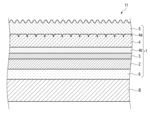
- FIG. 1 is a cross-sectional view of a decorative material including a decorative sheet according to one embodiment of the present invention.
- FIG. 2 is a cross-sectional view of a decorative material including a decorative sheet according to another embodiment of the present invention.
- Decorative material and decorative sheet Fig. 1 is a cross-sectional view of a decorative material including a decorative sheet according to one embodiment of the present invention.
- Fig. 2 is a cross-sectional view of a decorative material including a decorative sheet according to another embodiment of the present invention.
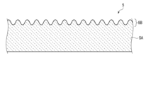
- Fig. 3 is a cross-sectional view of the surface protective layer of the decorative sheet of Figs. 1 and 2.
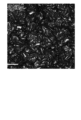
- Fig. 4 is a micrograph of the surface protective layer of a decorative sheet according to one example of the present invention.
- the cross section shown in Figure 3 is a cross section along the thickness direction of the surface protection layer.
- the micrograph in Figure 4 is a planar photograph taken with a laser microscope (OLS-4000, manufactured by Olympus Corporation).
- the decorative material 11 shown in Figures 1 and 2 includes a substrate B and a decorative sheet 1 attached thereto.
- the decorative material 11 is a decorative board.
- the decorative board may be a flat plate, or may be curved or folded.
- the decorative material 11 may have a shape other than a plate.
- the substrate B is a plate material.
- the plate material is, for example, a wood board, an inorganic board, a metal plate, or a composite board made of multiple materials.
- the substrate B may have a shape other than a plate.
- the decorative sheet 1 shown in FIG. 1 has a pattern layer 3 and a surface protection layer 5 provided in this order from the original fabric layer 2 side on one surface, which is the front side, of the original fabric layer 2, and a primer layer 6 provided on the other surface of the original fabric layer 2 (i.e., the surface facing the substrate B).
- a pattern layer 3 and the primer layer 6 may be omitted.
- the decorative sheet 1 shown in FIG. 2 has a pattern layer 3, an adhesive resin layer 4b, a transparent resin layer 4, and a surface protection layer 5 provided in this order from the original fabric layer 2 on one surface, i.e., the front side, of the original fabric layer 2, and a primer layer 6 provided on the other surface of the original fabric layer 2 (i.e., the surface facing the substrate B).
- the transparent resin layer 4 is provided with an embossed uneven pattern (embossed pattern 4a).
- one or more of the pattern layer 3, adhesive resin layer 4b, transparent resin layer 4, and primer layer 6 may be omitted. Also, the embossed pattern 4a does not have to be provided.
- At least one of the transparent resin layer 4 and the surface protective layer 5 may be laminated in multiple layers. Also, taking into consideration the adhesion between each layer, other known layers may be arranged. Also, a concealing layer (not shown) or the like may be provided between the base layer 2 and the primer layer 6 as appropriate.
- raw fabric layer 2 for example, any material selected from paper, synthetic resin, synthetic resin foam, rubber, nonwoven fabric, synthetic paper, metal foil, etc. can be used.
- paper include tissue paper, titanium paper, resin-impregnated paper, etc.
- synthetic resin include polyethylene, polypropylene, polybutylene, polystyrene, polycarbonate, polyester, polyamide, ethylene-vinyl acetate copolymer, polyvinyl alcohol, acrylic, etc.
- Examples of rubber include ethylene-propylene copolymer rubber, ethylene-propylene-diene copolymer rubber, styrene-butadiene copolymer rubber, styrene-isoprene-styrene block copolymer rubber, styrene-butadiene-styrene block copolymer rubber, polyurethane, etc.
- Examples of nonwoven fabric include organic and inorganic nonwoven fabrics.
- Examples of metals for the metal foil include aluminum, iron, gold, silver, etc.
- the raw fabric layer 2 may be a sheet made of the same resin composition as the transparent resin layer 4. In this case, the raw fabric layer 2 is obtained by forming a resin material or a resin composition into a film shape. Examples of the forming method include calendar molding and extrusion molding.
- the base fabric layer 2 preferably has a colored layer made of a synthetic resin mixed with an inorganic pigment, and a skin layer made of synthetic resin.
- the thickness of the skin layer is preferably 3 ⁇ m to 20 ⁇ m, and the ratio of the thickness of the skin layer to the colored layer is preferably 1:6 to 1:50.
- the outermost layer is a skin layer that does not contain pigment. It is preferable to provide a skin layer on both sides of the colored layer. If the skin layer is made thicker and its ratio to the colored layer is increased, the ratio of the colored layer will decrease, and the hiding power will decrease, which is not preferable.
- the thickness of the original fabric layer 2 is preferably 50 ⁇ m or more and 150 ⁇ m or less. If the original fabric layer 2 is less than 50 ⁇ m, the performance of covering the unevenness of the base (unevenness) decreases. On the other hand, if the thickness of the original fabric layer 2 exceeds 150 ⁇ m, there is a risk of defects such as whitening and cracks occurring during bending.
- the inorganic pigment may be a known inorganic pigment, such as titanium oxide, which is used to provide hiding properties.
- the raw cloth layer 2 plays a role in hiding the pattern of the substrate B.
- the light transmittance is preferably 40% or less. If the hiding properties are low, the pattern of the design layer 3 and the pattern of the substrate B will be mixed, which is not preferable.
- the mixed amount of the inorganic pigment is preferably 5 parts by mass or more and 50 parts by mass or less, based on 100 parts by mass of the resin material.
- the inorganic pigment contained is not particularly limited, but examples thereof include natural inorganic pigments and synthetic inorganic pigments.
- natural inorganic pigments include earth pigments, calcined earth, and mineral pigments.
- synthetic inorganic pigments include oxide pigments, hydroxide pigments, sulfide pigments, silicate pigments, phosphate pigments, carbonate pigments, metal powder pigments, carbon pigments, etc.
- synthetic inorganic pigment a mixed pigment of one or more of natural inorganic pigments and synthetic inorganic pigments may be used.
- an organic pigment such as carbon black may be used in combination.
- additives such as fatty acid metal salts may be added to inorganic pigments to improve dispersibility and extrusion suitability.
- a substrate with an inactive surface such as an olefin-based substrate
- Pattern Layer A pattern layer 3 for adding a pattern to the decorative sheet 1 can be provided on the surface of the base fabric layer 2.
- the pattern may be a wood grain pattern, a stone grain pattern, a sand grain pattern, a tiled pattern, a brickwork pattern, a cloth pattern, a leather-striped pattern, a geometric figure, or the like.
- a base solid ink layer (not shown) may be provided between the base layer 2 and the pattern layer 3 depending on the level of the desired design.
- the base solid ink layer is provided so as to cover the entire surface of the base layer 2.
- the base solid ink layer may also be multi-layered, with two or more layers, as necessary for hiding properties, etc.
- the pattern layer 3 may be formed by laminating the number of plates required to express the desired design. In this way, the pattern layer 3 and the base solid ink layer can be combined in various ways depending on the desired design, that is, the design to be expressed, but there are no particular limitations.
- the constituent materials of the base solid ink layer and the design layer 3 are not particularly limited.
- printing inks or coating agents obtained by dissolving or dispersing a matrix and a colorant such as a dye or pigment in a solvent can be used as the constituent materials of the base solid ink layer and the design layer 3.
- a colorant such as a dye or pigment in a solvent
- various synthetic resins such as oil-based nitrocellulose resin, two-liquid urethane resin, acrylic resin, styrene resin, polyester resin, urethane resin, polyvinyl resin, alkyd resin, epoxy resin, melamine resin, fluorine resin, silicone resin, and rubber resin, or mixtures or copolymers thereof can be used.
- inorganic pigments such as carbon black, titanium white, zinc oxide, red oxide, yellow lead, Prussian blue, and cadmium red
- organic pigments such as azo pigments, lake pigments, anthraquinone pigments, phthalocyanine pigments, isoindolinone pigments, and dioxazine pigments, or mixtures thereof can be used.
- toluene, xylene, ethyl acetate, butyl acetate, methyl alcohol, ethyl alcohol, isopropyl alcohol, acetone, methyl ethyl ketone, methyl isobutyl ketone, cyclohexanone, water, etc., or mixtures thereof, etc. can be used.
- functional additives such as extender pigments, plasticizers, dispersants, surfactants, tackifiers, adhesive aids, drying agents, hardeners, hardening accelerators, and hardening retarders may be added to the base solid ink layer and the pattern layer 3 to impart various functions.
- the base solid ink layer and the design layer 3 can be formed by various printing methods such as gravure printing, offset printing, screen printing, electrostatic printing, and inkjet printing.
- the base solid ink layer covers the entire surface of the base layer 2, it can also be formed by various coating methods such as roll coating, knife coating, microgravure coating, and die coating. These printing and coating methods may be selected separately depending on the layer to be formed, but it is more efficient to select the same method and process them all at once.
- the thickness of the pattern layer 3 is preferably 3 ⁇ m or more and 20 ⁇ m or less. When the thickness of the pattern layer 3 is within this range, the printing can be made clear, the printing workability when manufacturing the decorative sheet 1 is improved, and manufacturing costs can be reduced.
- the resin material used as the main component of the transparent resin layer 4 is preferably made of an olefin-based resin, and in addition to polypropylene, polyethylene, polybutene, etc., ⁇ -olefins (e.g., propylene, 1-butene, 1-pentene, 1-hexene, 1-heptene, 1-octene, 1-nonene, 1-decene, 1-undecene, 1-dodecene, tridecene, 1-tetradecene, 1-pentadecene, 1-hexadecene, 1-heptadecene, 1-octadecene, 1-nonadecene, 1-eicosene, 3-methyl-1-butene, 3-methyl-1-pentene, 3-ethyl-1-pentene, 4-methyl-1-pentene, 4-methyl-1-hexene, 4,4-dimethyl-1-pent ...
- copolymers examples include those obtained by homopolymerizing or copolymerizing two or more of ⁇ -olefins (such as ethylene-vinyl acetate copolymer, ethylene-vinyl alcohol copolymer, ethylene-methyl methacrylate copolymer, ethylene-ethyl methacrylate copolymer, ethylene-butyl methacrylate copolymer, ethylene-methyl acrylate copolymer, ethylene-ethyl acrylate copolymer, ethylene-butyl acrylate copolymer, etc.) with ethylene or ⁇ -olefins and other monomers, such as ethylene-vinyl acetate copolymer, ethylene-vinyl alcohol copolymer, ethylene-methyl methacrylate copolymer, ethylene-ethyl acrylate copolymer, ethylene-butyl acrylate copolymer, etc.
- ⁇ -olefins such as ethylene-vin
- main component refers to 90% or more by mass of the target material.
- the thickness of the transparent resin layer 4 is preferably 50 ⁇ m or more and 100 ⁇ m or less. If it is less than 50 ⁇ m, the effect of improving the scratch resistance of the surface of the transparent resin layer 4 is low, and there is little point in providing the transparent resin layer 4. If the thickness of the transparent resin layer 4 exceeds 100 ⁇ m, the rigidity of the decorative sheet 1 is too high, and there is a risk of problems such as whitening and cracking occurring during bending.
- the thickness of the transparent resin layer 4 may be less than 50 ⁇ m.
- the resin composition constituting the transparent resin layer 4 may contain various functional additives such as heat stabilizers, light stabilizers, ultraviolet absorbers, antiblocking agents, catalyst scatterers, colorants, light scattering agents, and gloss adjusters, as necessary. These various functional additives can be appropriately selected from well-known additives.
- the adhesive used to bond the pattern layer 3 and the transparent resin layer 4 can be any material selected depending on the bonding method.
- bonding methods include lamination methods using heat lamination, extrusion lamination, dry lamination, etc., and the adhesive can be selected from acrylic, polyester, polyurethane, etc. Due to its cohesive strength, a two-liquid curing type urethane material that utilizes the reaction between isocyanate and polyol is usually desirable.
- lamination method for the transparent resin layer 4 but methods using heat and pressure, extrusion lamination, dry lamination, etc. are commonly used.
- the transparent resin layer 4 may also be provided with an embossed pattern (embossed pattern 4a).
- Ink can be embedded in the embossed pattern 4a to further improve the design.
- the embossed pattern 4a can be provided by a method in which a sheet that has been laminated using various methods is first embossed using heat and pressure, or by providing a pattern on a cooling roll and embossing the sheet at the same time as extrusion lamination.
- embossed pattern layer 3 and the transparent resin layer 4 are bonded together by heat or dry lamination at the same time as extrusion.
- an adhesive resin layer 4b may be provided between the pattern layer 3 and the transparent resin layer 4.
- an adhesive resin layer 4b may be provided between the transparent resin layer 4 and the adhesive.
- lamination can be performed by co-extrusion of the transparent resin layer 4 and the adhesive resin layer 4b.
- the adhesive resin layer 4b can be an acid-modified resin such as polypropylene, polyethylene, or acrylic resin.
- the thickness of the adhesive resin layer 4b is desirably 2 ⁇ m or more in order to improve adhesion.
- the uneven structure can be expressed by the cut level difference Rdc.
- “Cut level difference Rdc” is a surface property parameter defined in JIS B0601:2013.
- the cut level difference Rdc indicates the cut level difference of the roughness curve and expresses the steepness of the uneven shape.
- the position of the highest peak of the roughness curve is the reference for the cut level c.
- c (Rmr1) is the cut level when the load length ratio Rmr of the roughness curve is 10%
- c (Rmr2) is the cut level when the load length ratio Rmr of the roughness curve is 25%.
- the cut level difference Rdc ( ⁇ m) of the roughness curve is the difference between the cut level c (Rmr1) and the cut level c (Rmr2).
- the Rdc of the transparent resin layer 4 is preferably 0.2 ⁇ m or more and 2.9 ⁇ m or less. If the Rdc is smaller than 0.2 ⁇ m, the effect of embedding the ink tends to be weaker. Also, if the Rdc is larger than 2.9 ⁇ m, when the surface protection layer 5 is formed on the transparent resin layer 4, the touch tends to be rough and gritty rather than moist.
- the Rdc of the transparent resin layer 4 is preferably 0.2 ⁇ m or more and 1.0 ⁇ m or less.
- the surface protection layer 5 has a core portion 5A and a ridge portion 5B that protrudes in a ridge shape from one surface of the core portion 5A. This forms an uneven shape in the surface protection layer 5.
- the "ridge shape” refers to a shape that is elongated and raised, and is linearly connected in a plan view.
- the ridge portion 5B may be curved or linear in a plan view, but is preferably curved from the viewpoint of the fingerprint resistance of the decorative sheet 1.
- the ridge portion 5B refers to, for example, the portion from the lowest part to the highest part of the uneven shape of the surface protection layer 5
- the core portion 5A refers to the portion of the surface protection layer 5 excluding the ridge portion 5B.
- the cross-sectional shape of the ridge portion 5B in the thickness direction of the surface protection layer 5 may be a sine wave shape.
- the sine wave shape referred to here means a shape in which the line extending from the lowest point to the highest point of the ridge portion 5B can be expressed as a sine wave.
- Fig. 3 is a cross-sectional view showing a schematic cross-section of the ridge portion 5B of the surface protective layer 5 (cross-section in the thickness direction of the surface protective layer 5), and Fig. 4 is a planar photograph showing the structure of the surface of the surface protective layer 5.
- Fig. 4 is a planar photograph obtained using a laser microscope (OLS-4000, manufactured by Olympus Corporation).
- the ridged portion 5B is elongated and raised, and is connected linearly in plan view. As described below, the ridged portion 5B is formed by irradiating the surface of the ionizing radiation curable resin with light of a specific wavelength, causing the cured film of the ionizing radiation curable resin to buckle.
- the shape of the ridge portion 5B can be expressed by the ratio RSm/Ra of the surface roughness index RSm ( ⁇ m) in the horizontal direction (the planar direction of the surface protective layer 5, the left-right direction in FIG. 3) to the surface roughness index Ra ( ⁇ m) in the vertical direction (the depth direction of the ridge portion 5B, the thickness direction of the surface protective layer 5, the up-down direction in FIG. 3).
- the ratio RSm/Ra is preferably in the range of 10 to 600, more preferably in the range of 10 to 400, and even more preferably in the range of 10 to 300. More preferably, RSm/Ra is in the range of 10 to 250.
- the surface roughness indices Ra and RSm are measured using a line roughness gauge and are measurements made in accordance with JIS B0601.
- the thickness t of the surface protective layer 5 is preferably within the range of 2 to 20 ⁇ m. More preferably, the thickness t of the surface protective layer 5 is within the range of 5 to 20 ⁇ m. If the thickness t of the surface protective layer 5 is less than 2 ⁇ m, the shaping by the vacuum ultraviolet light does not penetrate deeply, making it difficult to achieve a low gloss. Furthermore, if the thickness t of the surface protective layer 5 is greater than 20 ⁇ m, the processability decreases and the layer is more likely to whiten when bent.
- the thickness of the surface protective layer 5 is the thickness of a layer that has the same apparent area and volume as the surface protective layer 5 and has a flat surface.
- the thickness of the surface protective layer 5 is determined, for example, by the following method. First, a cross section parallel to the thickness direction of the surface protective layer 5 and perpendicular to the length direction of the ridge portion 5B is imaged. Next, from this cross-sectional image, the dimension of the surface protective layer 5 in the width direction of the ridge portion 5B and the area of the cross section of the surface protective layer 5 are determined. The thickness of the surface protective layer 5 is a value obtained by dividing this area by the above dimension. The thickness of the surface protective layer 5 is determined by observing the cross section with a scanning electron microscope and averaging 25 points.
- the thickness of the surface protective layer 5 can be determined as described in the examples described later. Note that when the coating liquid for the surface protective layer described later does not contain a solvent, the thickness of the coating film made of the coating liquid for the surface protective layer is equal to the thickness of the surface protective layer 5.
- the surface protective layer 5 can be formed by various printing methods such as gravure printing, offset printing, screen printing, electrostatic printing, inkjet printing, etc.
- the surface protective layer 5 covers the entire surface of the front side of the raw fabric layer 2, it can also be formed by various coating methods such as roll coating, knife coating, microgravure coating, die coating, etc. These printing or coating methods may be selected separately depending on the layer to be formed, or the same method may be selected and processed all at once.
- the pattern layer 3 and the surface protective layer 5 may be synchronized from the viewpoint of design.
- the gravure printing method allows for relatively high speed processing, so it is advantageous in terms of cost and is preferable.
- synchronization means that 50% or more, preferably 70% or more, and most preferably 90% or more of the portion where the surface protective layer 5 is formed overlaps with the pattern portion of the pattern layer 3 in a planar view.
- the thickness of the surface protective layer 5 can be adjusted by adjusting the amount of coating in the printing and coating methods described above.
- the amount of coating can be calculated from the mass difference between a base sheet (including the base layer) with the surface protective layer 5 formed and one without it, produced using various printing and coating methods.
- the surface protective layer 5 includes a cured product of an ionizing radiation curable resin.
- the main material of the surface protective layer 5 is preferably an ionizing radiation curable resin.
- the main material means that the main material contains 60 parts by mass or more, more preferably 70 parts by mass or more, and most preferably 80 parts by mass or more per 100 parts by mass of the surface protective layer 5.
- ionizing radiation refers to a charged particle beam such as an electron beam.
- the ionizing radiation curable resin is cured by irradiation with ionizing radiation.
- the ionizing radiation curable resin can also be cured by ultraviolet irradiation.
- the ionizing radiation curable resin used here is cured by irradiation with light having a wavelength of 200 nm or less, and has a large absorption coefficient for this light.
- known materials such as various monomers and commercially available oligomers can be used, for example, (meth)acrylic resins, silicone resins, polyester resins, urethane resins, amide resins, and epoxy resins can be used.
- the ionizing radiation curable resin may be either an aqueous resin or a non-aqueous (organic solvent-based) resin, and may be used alone or in combination of multiple types.
- the ionizing radiation curable resin includes an ionizing radiation curable resin having a cyclic structure.
- the ionizing radiation curable resin preferably includes an ionizing radiation curable resin having a cyclic structure such that the portion of the cyclic structure occupies an amount within a range of 2 to 45% by mass of the entire ionizing radiation curable resin. It is more preferable that the ionizing radiation curable resin includes an ionizing radiation curable resin having a cyclic structure such that the portion of the cyclic structure occupies an amount within a range of 5 to 45% by mass of the entire ionizing radiation curable resin.
- the ionizing radiation curable resin includes an ionizing radiation curable resin having a cyclic structure (hereinafter also referred to as a cyclic compound), a decorative sheet having excellent resistance to coloring and contamination can be provided. This effect is believed to be due to the following reasons.
- the surface protective layer 5 is formed by a first irradiation step and a second irradiation step.
- first irradiation step a crosslinking reaction of the ionizing radiation curable resin occurs only on the surface of the coating film, and in the second irradiation step, the entire coating film is cured.
- the first irradiation step is generally performed in a nitrogen gas atmosphere with a low oxygen concentration.
- a nitrogen gas atmosphere with a low oxygen concentration is a hydrophobic atmosphere.
- the cyclic structure portion is hydrophobic. Therefore, the cyclic structure portion of the cyclic compound is easily exposed to the surface of the coating film.
- the surface of the surface protective layer 5 has more cyclic structure portions of the cyclic compound than the region other than the surface. Since the cyclic structure portion of the cyclic compound is bulky, when a hair dye adheres to the surface protective layer 5, it prevents the dye molecules of the hair dye from coming into contact with the ionizing radiation curable resin that does not have a cyclic structure. As a result, it is thought that the ionizing radiation curable resin with a cyclic structure exhibits excellent resistance to coloring and contamination by the hair dye.
- the proportion Rc (mass %) of the "cyclic structure portion" in the entire ionizing radiation curable resin can be calculated by the following formula.
- Ring structure refers to a ring structure based on a carbon skeleton.
- the ring structure may be one in which the ring constituent atoms are only carbon (i.e., a carbocyclic ring), or one in which the ring constituent atoms are carbon and an element other than carbon (i.e., a heterocyclic ring).
- the ring structure may be a monocyclic ring or a polycyclic ring.
- the polycyclic ring may be a condensed ring, a spiro ring, or a bridged ring.
- the ring structure may be composed of, for example, one to four ring hydrocarbons. That is, the ring structure may be composed of, for example, one or two to four ring hydrocarbons.
- the number of ring constituent atoms in the ring structure is, for example, 5 or more, preferably 5 to 18, more preferably 6 to 18, and even more preferably 6 to 10.
- Examples of the cyclic structure include an isobornyl group, an adamantyl group, a dicyclopentanyl group, a cyclohexyl group, a cyclopentyl group, a cyclopentadienyl group, a 3,4-epoxycyclohexyl group, a 6,7-epoxydecahydro-1,4:5,8-dimethanonaphthalene group, a decahydronaphthalene group, a tricyclodecane group, a benzyl group, a phenyl group, etc.
- the isobornyl group, the adamantyl group, the dicyclopentanyl group, the 6,7-epoxydecahydro-1,4:5,8-dimethanonaphthalene group, and the tricyclodecane group correspond to a bridged ring and have a particularly bulky structure.
- the ionizing radiation curable resin having a cyclic structure may or may not have a substituent in the cyclic structure.
- the term "cyclic structure" refers to a ring portion that does not contain a substituent.
- the bulky substituent portion is also considered to function to prevent the dye molecules of the hair dye from coming into contact with the ionizing radiation curable resin that does not have a cyclic structure when the hair dye adheres to the surface protective layer 5.
- the ionizing radiation curable resin having a cyclic structure is preferably an acrylate.
- examples of the ionizing radiation curable resin having a cyclic structure include cyclohexyl (meth)acrylate, 3,3,5-trimethylcyclohexyl (meth)acrylate, 4-tert-butylcyclohexyl (meth)acrylate, cyclopentyl (meth)acrylate, dicyclopentanyl (meth)acrylate, 3,4-epoxycyclohexylmethylacrylate, 6,7-epoxydecahydro-1,4:5,8-dimethanonaphthalene-2-yl acrylate, tricyclodecane dimethanol diacrylate, isobornyl (meth)acrylate, and the like.
- acrylate 2-adamantylprop-2-enoate (i.e., 2-adamantyl acrylate), 1-adamantyl (meth)acrylate, 3-hydroxy-1-adamantyl (meth)acrylate, 2-methyl-2-adamantyl (meth)acrylate, 2-ethyl-2-adamantyl (meth)acrylate, 2-isopropyl-2-adamantyl (meth)acrylate, 1,3-adamantanediol di(meth)acrylate, benzyl (meth)acrylate, phenoxyethyl (meth)acrylate, and the like.
- the term "(meth)acrylate” is used herein to include acrylate, methacrylate, and combinations thereof.
- the ionizing radiation curable resin having a cyclic structure is, for example, monofunctional or bifunctional.
- the ionizing radiation curable resin having a cyclic structure is preferably monofunctional.
- the ionizing radiation curable resin having a cyclic structure is monofunctional, it is possible to obtain a surface protection layer having a better surface condition, i.e., a surface protection layer having wrinkles formed more uniformly on the surface.
- the ionizing radiation curable resin preferably contains an ionizing radiation curable resin having a cyclic structure in a proportion within the range of 10 to 85% by mass.
- the ionizing radiation curable resin more preferably contains an ionizing radiation curable resin having a cyclic structure in a proportion within the range of 10 to 80% by mass, and even more preferably contains an ionizing radiation curable resin having a cyclic structure in a proportion within the range of 30 to 60% by mass.
- the ionizing radiation curable resin preferably further contains an oligomer having 10 or less functionalities.
- an oligomer is preferably a urethane acrylate or an acrylic acrylate.
- the oligomer is preferably an oligomer having 2 to 10 functionalities.
- the oligomer preferably does not have a cyclic structure. In other words, the oligomer is preferably a chain acrylate.
- oligomers examples include EBECRYL9270 (difunctional urethane acrylate) (Daicel-Allnex Corporation), EBECRYL4666 (tetrafunctional urethane acrylate) (Daicel-Allnex Corporation), EBECRYL5129 (hexafunctional urethane acrylate) (Daicel-Allnex Corporation), UN-904 (10-functional urethane acrylate) (Negami Chemical Industries Co., Ltd.), and OAP-5000 (acrylic acrylate) (Negami Chemical Industries Co., Ltd.).
- the oligomers may be used alone or in combination of two or more types.
- the ionizing radiation curable resin preferably contains the above oligomer in a proportion within the range of 20 to 70% by mass.
- the ionizing radiation curable resin more preferably contains the oligomer in a proportion within the range of 25 to 60% by mass, and even more preferably 30 to 50% by mass.
- the above oligomer is preferably contained in the surface protective layer in an amount ranging from 25 to 200 parts by mass, more preferably from 30 to 150 parts by mass, based on 100 parts by mass of the ionizing radiation curable resin having a cyclic structure.
- the ionizing radiation curable resin further contains a monomer.
- a monomer is preferably an acrylate. It is preferable that the monomer is a monofunctional to tetrafunctional monomer. It is preferable that the monomer has a viscosity of about 100 mPa ⁇ s or less at 25°C. It is preferable that the monomer does not have a cyclic structure. In other words, it is preferable that the monomer is a chain acrylate.
- the monomer is contained in the surface protective layer, the scratch resistance of the surface protective layer can be improved. Furthermore, the monomer can reduce the viscosity of the coating liquid for the surface protective layer.
- Examples of the monomer include tripropylene glycol diacrylate, 1,6-hexanediol diacrylate, dipropylene glycol diacrylate, PO-modified neopentyl glycol diacrylate, trimethylolpropane triacrylate, trimethylolpropane ethoxy triacrylate, glycerin propoxy triacrylate, pentaerythritol, pentaerythritol ethoxy tetraacrylate, and pentaerythritol (tri/tetra)acrylate.
- the monomers may be used alone or in combination of two or more.
- the ionizing radiation curable resin preferably contains the above-mentioned monomer in a proportion within the range of 0 to 60% by mass.
- the ionizing radiation curable resin more preferably contains the monomer in a proportion within the range of 10 to 50% by mass, and even more preferably 20 to 40% by mass.
- the above monomer is preferably contained in the surface protective layer in an amount ranging from 10 to 1,000 parts by mass, more preferably from 20 to 800 parts by mass, based on 100 parts by mass of the ionizing radiation curable resin having a cyclic structure.
- the main component of the ionizing radiation curable resin is preferably an acrylate.
- the main component of the ionizing radiation curable resin means a component that accounts for 60 mass% or more of the ionizing radiation curable resin.
- the ionizing radiation curable resin preferably contains 70 mass parts or more of acrylate, and more preferably contains 80 mass parts or more.
- the average number of functional groups is preferably 1.1 or more.
- the average number of functional groups is preferably 2.0 or more. There is no upper limit to the average number of functional groups of the acrylate, but according to one example, it is 6.0 or less.
- the surface protection layer 5 may contain particles. By adding particles of an optimal particle size and optimal content, a uniform surface can be formed.
- organic materials such as polyethylene (PE) wax, polypropylene (PP) wax, and resin beads, or inorganic materials such as silica, glass, alumina, titania, zirconia, calcium carbonate, and barium sulfate can be used as particles.
- the average particle size (D50) of the particles is 10 ⁇ m or less. It is desirable that the average particle size (D50) of the particles is 3 ⁇ m or more.
- the average particle size (D50) of the particles is preferably 3 ⁇ m or more and 10 ⁇ m or less, and more preferably 4 ⁇ m or more and 10 ⁇ m or less.
- the surface protective layer 5 contains particles, wrinkles can be more uniformly formed on the coating surface in the first irradiation step described below. If large particles are used, the particles are more likely to fall off from the surface protective layer 5, which may make it difficult to achieve high scratch resistance. If the particles are small, the effect of forming wrinkles uniformly is small.
- the "average particle size (D50)" is the median size (D50) measured by a laser diffraction/scattering type particle size distribution measuring device. If the coating liquid for the surface protective layer contains particles, the surface protective layer 5 obtained from this coating liquid will also contain particles. The average particle size of the particles contained in the surface protective layer 5 can be determined by observing the cross section of the layer and averaging the particle sizes of multiple particles. The value obtained in this manner is substantially the same as the median size (D50) measured by a laser diffraction/scattering type particle size distribution measuring device. Therefore, the above-mentioned range of average particle sizes can also be interpreted as the range of average particle sizes of the particles contained in the surface protective layer 5.
- the particles are preferably contained in the surface protection layer 5 in an amount ranging from 0.5 to 10 parts by mass, assuming that the entire ionizing radiation curable resin is 100 parts by mass.
- the amount of particles added is more preferably within a range of 3 to 10 parts by mass, and even more preferably 4 to 10 parts by mass, assuming that the entire ionizing radiation curable resin is 100 parts by mass. Note that "100 parts by mass of ionizing radiation curable resin" refers to the parts by mass of the solid content of the resin.
- the effect of creating uniform wrinkles is particularly large.
- the particles are likely to fall off from the surface protective layer 5, making it difficult to achieve high scratch resistance.
- the effect of creating uniform wrinkles is small.
- photopolymerization initiator there are no particular limitations on the photopolymerization initiator, but examples include benzaphenone-based, acetophenone-based, benzoin ether-based, and thioxanthone-based initiators.
- the surface protective layer 5 may further contain additives such as antibacterial agents and antifungal agents to impart the required functions.
- additives such as antibacterial agents and antifungal agents to impart the required functions.
- it may further contain ultraviolet absorbers and light stabilizers as necessary. It is common to add any combination of ultraviolet absorbers such as benzotriazoles, benzoates, benzophenones, and triazines, and light stabilizers such as hindered amines.
- Hindered amine light stabilizers that can be used include, for example, bis(1,2,2,6,6-pentamethyl-4-piperidyl)[[3,5-bis(1,1-dimethylethyl)-4-hydroxyphenyl]methyl]butyl malonate (a representative example is BASF's product name "Tinuvin 144"), BASF's product name "Tinuvin 123”, and the reaction product of decanedioic acid bis(2,2,6,6-tetramethyl-1-(octyloxy)-4-piperidinyl) ester (1,1-dimethylethyl hydroperoxide) and octane.
- the hindered amine light stabilizer When the hindered amine light stabilizer is added to the surface protective layer 5, it is preferable to add it in the range of 0.05 parts by mass to 5 parts by mass to 100 parts by mass of the ionizing radiation curable resin.
- the amount of the hindered amine light stabilizer added is more preferably in the range of 0.2 parts by mass to 3 parts by mass. If the amount of the hindered amine light stabilizer added is less than 0.05 parts by mass, the effect of the stability of the resin against ultraviolet rays may be low. On the other hand, if it is more than 5 parts by mass, there is a high possibility that bleed-out may occur.
- the surface protective layer 5 can be formed by irradiating light of 200 nm or less to cure and shrink the vicinity of the surface to form a fine uneven shape, but in this case, if the hindered amine light stabilizer is contained in an amount of more than 3 parts by mass, it may inhibit the curing of the vicinity of the surface. In order to achieve both low gloss and weather resistance, it is desirable to contain the hindered amine light stabilizer in the range of 3 parts by mass or less.
- the glossiness of the surface protective layer 5 is preferably 10.0 or less. It is more preferable that the glossiness of the surface protective layer 5 is 5.0 or less.
- glossiness is the measured value when measured at an incidence angle of 60 degrees using a glossmeter conforming to JIS Z8741:1997.
- Primer layer 6 can be made of the same material as the pattern layer 3. Considering that the primer layer 6 is applied to the back surface of the decorative sheet 1 and is wound in a web form, inorganic fillers such as silica, alumina, magnesia, titanium oxide, barium sulfate, etc. may be added to avoid blocking and improve adhesion with the adhesive.
- the coating thickness of the primer layer 6 is preferably 0.1 ⁇ m or more and 3.0 ⁇ m or less, since the purpose is to ensure adhesion with the substrate B.
- the primer layer 6 is necessary when the original layer 2 has an inactive surface such as an olefin-based material, but is not particularly necessary when the surface is active.
- the decorative sheet 1 is manufactured, for example, by the following method.
- explanations regarding the design layer 3, transparent resin layer 4, adhesive resin layer 4b, and primer layer 6 are omitted here.
- a coating film made of a coating liquid for the surface protective layer is formed on one side of the base layer 2.
- the coating liquid for the surface protective layer contains an ionizing radiation curable resin, and, if necessary, particles and additives.
- the coating film made of the coating liquid for the surface protective layer can be formed, for example, by printing.
- the first irradiation step is carried out.
- the coating film is irradiated with light having a wavelength of 200 nm or less (hereinafter referred to as the first radiation).
- the ionizing radiation curable resin contained in the coating liquid for the surface protective layer has a large absorption coefficient for the first radiation. Therefore, the first radiation incident on the coating film can only reach a position several tens to several hundreds of nm away from the outermost surface. Therefore, in the first irradiation step, the crosslinking reaction proceeds in the surface region of the coating film to form an extremely thin cured film, while in other regions, the crosslinking reaction does not proceed and the coating film remains uncured.
- the coating film After the first irradiation process, the coating film has wrinkles on its surface that correspond to the ridged portion 5B.
- the inventor believes that the reason wrinkles form on the coating film surface as a result of the first irradiation process is as follows.
- the first radiation can only reach a position that is tens to hundreds of nanometers away from the outermost surface of the coating film.
- the crosslinking reaction of the ionizing radiation curable resin occurs only on the surface of the coating film, and areas that are more than tens to hundreds of nanometers away from the outermost surface are uncured and contain highly fluid molecules. These highly fluid molecules swell the cured film, thereby increasing its volume. The increase in volume in the in-plane direction causes the cured film to buckle, resulting in wrinkles on the surface of the coating film.
- the first radiation can be extracted from excimer VUV light.
- Excimer VUV light can be produced from a lamp that uses a rare gas or a rare gas halide compound.
- a lamp that contains a rare gas or a rare gas halide compound gas When high-energy electrons are provided from the outside to a lamp that contains a rare gas or a rare gas halide compound gas, a large number of discharge plasmas (dielectric barrier discharges) are generated.
- This plasma discharge excites the atoms of the discharge gas (rare gas), which momentarily enters an excimer state.
- light is emitted in a wavelength range specific to that excimer.
- the gas used in the excimer lamp may be any conventional gas that emits light of 200 nm or less.
- the gas may be a rare gas such as Xe, Ar, or Kr, or a mixture of a rare gas such as ArBr or ArF with a halogen gas.
- the central wavelength of the excimer lamp varies depending on the gas, and may be, for example, about 172 nm (Xe), about 126 nm (Ar), about 146 nm (Kr), about 165 nm (ArBr), or about 193 nm (ArF).
- a xenon lamp that emits excimer light with a central wavelength of 172 nm as the light source. Also, considering the cost of maintaining the equipment and the availability of materials, it is preferable to use a xenon lamp as the light source.
- the first irradiation step is carried out in an atmosphere with a low oxygen concentration.
- Oxygen has a large absorption coefficient for light of 200 nm or less. Therefore, the first irradiation step is preferably carried out in, for example, a nitrogen gas atmosphere.
- the oxygen concentration in the gas phase in the first irradiation step i.e., the residual oxygen concentration in the reaction atmosphere, is preferably 2000 ppm or less, and more preferably 1000 ppm or less.
- oxygen in the atmosphere inhibits radical polymerization. Therefore, the residual oxygen concentration in the reaction atmosphere affects the formation of wrinkles on the coating surface. Therefore, changing the residual oxygen concentration in the reaction atmosphere can also change the surface properties of the surface protective layer 5.
- the integrated light amount of the first radiation is preferably 0.5 mJ/ cm2 to 200 mJ/ cm2 , more preferably 1 mJ/ cm2 to 100 mJ/ cm2 , even more preferably 3 mJ/ cm2 to 50 mJ/ cm2 , and most preferably 5 mJ/ cm2 to 30 mJ/ cm2 . If the integrated light amount is reduced, the cured film expands less in the in-plane direction. If the integrated light amount is increased, the surface condition of the coating film deteriorates.
- the second irradiation step is carried out.
- the coating film is irradiated with a second radiation to harden the entire coating film. This results in the surface protection layer 5.
- the second radiation is ionizing radiation such as an electron beam, or ultraviolet light having a longer wavelength than the first radiation.
- ultraviolet light When ultraviolet light is used as the second radiation, the ultraviolet light has a wavelength at which the ionizing radiation curable resin exhibits a small absorption coefficient.
- the accumulated light amount of the second radiation is preferably 10 mJ/cm 2 or more and 500 mJ/cm 2 or less, more preferably 50 mJ/cm 2 or more and 400 mJ/cm 2 or less, and even more preferably 100 mJ/cm 2 or more and 300 mJ/cm 2 or less.
- the decorative sheet 1 according to this embodiment has a surface protective layer 5 with an uneven surface.
- the decorative sheet 1 according to this embodiment also contains a cured product of an ionizing radiation curable resin in the surface protective layer 5, and the ionizing radiation curable resin contains a predetermined amount of an ionizing radiation curable resin having a cyclic structure. This gives the decorative sheet 1 according to this embodiment low gloss and excellent resistance to coloring and staining.
- the decorative sheet 1 according to this embodiment has a surface protective layer 5 with an uneven surface, the gloss (glossiness) of the surface protective layer can be adjusted even if the surface protective layer does not contain a gloss adjuster (matt additive).
- Gloss adjusters reduce the oil repellency of the layer formed from the resin material, making it more susceptible to fingerprints. Since the surface protective layer 5 does not contain a gloss adjuster, it does not absorb oil and has relatively improved oil repellency. For this reason, in various situations, such as during on-site construction, when assembling furniture, and during the resident's daily life, fingerprints are less likely to adhere to the decorative sheet 1 having the surface protective layer 5.
- the surface protective layer 5 is configured with an uneven surface, which improves the oil repellency of the surface protective layer 5 and makes it possible to suppress oil stains and adsorption of contaminants onto the surface of the decorative sheet 1.
- the particles of the gloss adjusting agent do not fall off when the surface of the decorative sheet 1 is scratched, making it possible to prevent changes in gloss or scratches on the surface of the decorative sheet 1.
- the surface protection layer 5 is configured without a gloss adjuster, so that whitening that can occur due to gloss adjusters does not occur during bending, making it possible to prevent deterioration of bending workability.
- Oxygen in the gas phase not only absorbs short-wavelength ultraviolet light, but also inhibits radical polymerization.
- the effect of oxygen contained in the gas phase on radical polymerization is greatest in the portion of the coating film made of ionizing radiation curable resin adjacent to the gas phase, and decreases as the distance from the coating film surface increases. Therefore, by changing the oxygen concentration in the gas phase in the first irradiation step, it is possible to change the relationship between the distance from the coating film surface and the progress of the crosslinking reaction.
- the thickness of the cured film formed on the surface of the coating by the first irradiation process and the degree of expansion of the cured film in the in-plane direction according to the progress of the crosslinking reaction change.
- the thickness of the cured film and the degree of expansion of the cured film in the in-plane direction are also affected by the integrated light amount in the first irradiation process.
- the thickness of the cured film and the degree of expansion of the cured film in the in-plane direction also affect the surface properties of the surface protective layer.
- the particle size and amount of particles added in the coating film, as well as the thickness of the coating film also affect the formation of wrinkles.
- Example 1 An olefin film (manufactured by RIKEN TECHNOS CORPORATION) having a thickness of 55 ⁇ m was used as the base fabric layer 2, one side of the base fabric layer 2 was subjected to a corona treatment, and a pattern was printed on the one side to form a pattern layer 3.
- the pattern layer 3 was formed using a two-component urethane ink (V180; manufactured by Toyo Ink Co., Ltd.) to which 0.5 parts by mass of a hindered amine-based light stabilizer (Chimasorb 944; manufactured by BASF Corporation) was added relative to the binder resin content of the ink.
- a primer layer 6 was formed on the back surface of the base layer 2.
- the primer layer 6 was formed by printing with the same two-component urethane ink as the pattern layer 3.
- the coating liquid for a surface protective layer was applied onto the design layer 3.
- the thickness of the coating liquid for a surface protective layer was 5 ⁇ m.
- the coating liquid for a surface protective layer was a mixture of the following ionizing radiation curable resin and the following additives (particles, photopolymerization initiator).
- Ionizing radiation curable resin Resin 1 (resin having a cyclic structure): Type: 2-adamantylprop-2-enoate (steric cyclic acrylate) Blend: 40 parts by weight Resin 2 (monomer): Type: Tripropylene glycol diacrylate (TPGDA) (bifunctional acrylate) Formulation: 30 parts by weight Resin 3 (oligomer): Type: EBECRYL 9270 (bifunctional urethane acrylate) (manufactured by Daicel Allnex Co., Ltd.) Formulation: 30 parts by weight, particles Product name: Silicea 250N (manufactured by Fuji Silysia Chemical Ltd.) Particle size: 5 ⁇ m Blend: 5 parts by mass/photopolymerization initiator Product name: Omnirad184 (manufactured by IGM Resins) Formulation: 3 parts by weight.
- the cyclic structure is an adamantyl group (C 10 H 15 ). Since the adamantyl group is a bridged ring, the resin 1 used in Example 1 can be called a stereocyclic acrylate.
- the first irradiation step was carried out. Specifically, under atmospheric pressure and in a nitrogen gas atmosphere with an oxygen concentration of 100 ppm, the surface of the coating film made of the coating liquid for surface protection layer was irradiated with ultraviolet light having a wavelength of 172 nm using a Xe excimer lamp so that the cumulative light amount was 30 mJ/ cm2 . This caused wrinkles to form on the surface of the coating film.
- the coating film was irradiated with ultraviolet light using a high-pressure mercury lamp at 200 mJ/cm 2 to cure the entire coating film, thereby forming a surface protective layer 5.
- Example 2 A decorative sheet was obtained in the same manner as in Example 1, except that Resin 1 (a resin having a cyclic structure) used in Example 1 was replaced with the following.
- the resin 1 (a resin having a cyclic structure) used in Example 2 the cyclic structure is a dicyclopentanyl group (C 10 H 15 ). Since the dicyclopentanyl group is a bridged ring, the resin 1 used in Example 2 can be called a stereocyclic acrylate.
- Example 3 A decorative sheet was obtained in the same manner as in Example 1, except that Resin 1 (a resin having a cyclic structure) used in Example 1 was replaced with the following.
- Type 4-tert-butylcyclohexyl acrylate (cyclic acrylate) Composition: 40 parts by weight.
- the cyclic structure is the ring portion (C 6 H 10 ) of a 4-tert-butylcyclohexyl group.
- Example 4 A decorative sheet was obtained in the same manner as in Example 1, except that Resin 1 (a resin having a cyclic structure) used in Example 1 was replaced with the following.
- Resin 1 (resin having a cyclic structure) used in Example 4 the cyclic structure is a cyclohexyl group (C 6 H 11 ).
- Example 5 A decorative sheet was obtained in the same manner as in Example 1, except that the ionizing radiation curable resin used in Example 1 was replaced with the following.
- Resin 1 (resin having a cyclic structure): Type: 2-adamantylprop-2-enoate (steric cyclic acrylate) Blend: 10 parts by weight
- Resin 2 (monomer): Type: Tripropylene glycol diacrylate (TPGDA) (bifunctional acrylate)
- TPGDA Tripropylene glycol diacrylate
- Formulation 30 parts by weight
- Resin 3 (oligomer) Type: EBECRYL 9270 (bifunctional urethane acrylate) (manufactured by Daicel Allnex Co., Ltd.) Composition: 60 parts by weight.
- Example 6 A decorative sheet was obtained in the same manner as in Example 1, except that the ionizing radiation curable resin used in Example 1 was replaced with the following.
- Resin 1 (resin having a cyclic structure): Type: 2-adamantylprop-2-enoate (steric cyclic acrylate) Formulation: 80 parts by weight
- Resin 3 (oligomer): Type: EBECRYL 9270 (bifunctional urethane acrylate) (manufactured by Daicel Allnex Co., Ltd.) Composition: 20 parts by weight.
- Example 7 A decorative sheet was obtained in the same manner as in Example 1, except that Resin 1 (a resin having a cyclic structure) used in Example 1 was replaced with the following.
- the resin 1 (a resin having a cyclic structure) used in Example 7 the cyclic structure is a tricyclodecane group (C 10 H 14 ). Since the tricyclodecane group is a bridged ring, the resin 1 used in Example 7 can be called a stereocyclic acrylate.
- Example 8 A decorative sheet was obtained in the same manner as in Example 1, except that Resin 3 (oligomer) used in Example 1 was replaced with the following.
- Example 9 A decorative sheet was obtained in the same manner as in Example 1, except that Resin 3 (oligomer) used in Example 1 was replaced with the following.
- Example 10 A decorative sheet was obtained in the same manner as in Example 1, except that Resin 3 (oligomer) used in Example 1 was replaced with the following.
- Example 11 A decorative sheet was obtained in the same manner as in Example 1, except that Resin 3 (oligomer) used in Example 1 was replaced with the following.
- Example 12 A decorative sheet was obtained in the same manner as in Example 1, except that the ionizing radiation curable resin used in Example 1 was replaced with the following.
- Resin 1 (resin having a cyclic structure): Type: 2-adamantylprop-2-enoate (steric cyclic acrylate) Blend: 4 parts by weight
- Resin 2 (monomer): Type: Tripropylene glycol diacrylate (TPGDA) (bifunctional acrylate)
- TPGDA Tripropylene glycol diacrylate
- Formulation 66 parts by weight
- Resin 3 (oligomer) Type: EBECRYL 9270 (bifunctional urethane acrylate) (manufactured by Daicel Allnex Co., Ltd.) Formulation: 30 parts by weight.
- Example 13 A decorative sheet was obtained in the same manner as in Example 1, except that the ionizing radiation curable resin used in Example 1 was replaced with the following.
- Resin 1 (resin having a cyclic structure): Type: 2-adamantylprop-2-enoate (steric cyclic acrylate) Formulation: 90 parts by weight
- Resin 3 (oligomer): Type: EBECRYL 9270 (bifunctional urethane acrylate) (manufactured by Daicel Allnex Co., Ltd.) Composition: 10 parts by weight.
- Example 1 A decorative sheet was obtained in the same manner as in Example 1, except that the amount of the particles added in Example 1 was changed as follows, and the first irradiation step carried out in Example 1 was not carried out.
- Example 2 A decorative sheet was obtained in the same manner as in Example 1, except that Resin 1 (a resin having a cyclic structure) used in Example 1 was replaced with the following.
- Resin 1 a resin having a cyclic structure
- Type Butyl acrylate (chain acrylate) Composition: 40 parts by weight.
- Example 3 A decorative sheet was obtained in the same manner as in Example 1, except that the ionizing radiation curable resin used in Example 1 was replaced with the following.
- Resin 2 (monomer): Type: Tripropylene glycol diacrylate (TPGDA) (bifunctional acrylate) Formulation: 70 parts by weight
- Resin 3 (oligomer): Type: EBECRYL 9270 (bifunctional urethane acrylate) (manufactured by Daicel Allnex Co., Ltd.) Formulation: 30 parts by weight.
- TPGDA Tripropylene glycol diacrylate
- oligomer Type: EBECRYL 9270 (bifunctional urethane acrylate) (manufactured by Daicel Allnex Co., Ltd.) Formulation: 30 parts by weight.
- the thickness of the surface protective layer was measured as follows.
- the decorative sheet was embedded in a resin such as a cold-curing epoxy resin or a UV-curable resin, and the resin was fully cured.
- the decorative sheet was cut so that the cross section of the decorative sheet appeared, and mechanical polishing was performed to obtain a measurement surface.
- the cross section of the surface protective layer was imaged using a scanning electron microscope SIGMA 500 manufactured by Carl Zeiss Microscopy. In this image capture, the acceleration voltage was set to 0.5 keV (low acceleration voltage), the shooting mode was set to SE2 mode, and the magnification was set to 2000 times.
- the dimensions of the surface protective layer in the width direction of the ridge-shaped portion and the area of the cross section of the surface protective layer were obtained.
- the thickness of the surface protective layer was calculated by dividing this area by the above dimensions.
- the measurement was performed at any 25 points, and the average value of the 25 points was defined as the "thickness t of the surface protective layer".
- the "thickness t of the surface protective layer” was equal to the thickness of the coating film made of the coating liquid for the surface protective layer.
- Fingerprint wiping rate (%) (glossiness after wiping/initial glossiness) x 100
- the evaluation criteria were as follows. A: 70% or more and less than 250% B: 50% or more and less than 70%, or 250% or more and less than 300% C: Less than 50%, or 300% or more.
- the evaluation criteria were as follows. AA: No change in appearance. A: Slight change in gloss. B: Slight scratches. C: Clear scratches.
- the above table shows the composition of the ionizing radiation curable resin, as well as the proportion (mass %) of the "ring structure portion of resin 1 (resin having a ring structure)" in the entire ionizing radiation curable resin.
- the "ring structure portion” refers to the ring portion that does not contain a substituent.
- the decorative sheet according to Comparative Example 1 did not have an uneven structure on the surface of the surface protective layer that included a plurality of ridge-like portions, each of which protruded in a ridge-like shape. Furthermore, the decorative sheets according to Comparative Examples 2 and 3 did not contain an ionizing radiation curable resin having a cyclic structure. None of the decorative sheets according to Comparative Examples 1 to 3 were able to achieve excellent resistance to coloring and contamination.
- Reference Signs List 1 decorative sheet
- 2 base fabric layer
- 3 pattern layer
- 4 transparent resin layer
- 4a embossed pattern
- 4b adhesive resin layer
- 5 surface protective layer
- 5A core portion
- 5B ridge portion
- 6 primer layer
- 11 decorative material
- B base material.
Landscapes
- Engineering & Computer Science (AREA)
- Architecture (AREA)
- Chemical & Material Sciences (AREA)
- Structural Engineering (AREA)
- Civil Engineering (AREA)
- Organic Chemistry (AREA)
- Polymers & Plastics (AREA)
- Health & Medical Sciences (AREA)
- Medicinal Chemistry (AREA)
- Chemical Kinetics & Catalysis (AREA)
- Laminated Bodies (AREA)
- Life Sciences & Earth Sciences (AREA)
- Materials Engineering (AREA)
- Wood Science & Technology (AREA)
- Physics & Mathematics (AREA)
- Plasma & Fusion (AREA)
Priority Applications (3)
| Application Number | Priority Date | Filing Date | Title |
|---|---|---|---|
| JP2025537816A JPWO2025028233A1 (https=) | 2023-08-02 | 2024-07-12 | |
| KR1020267006088A KR20260048595A (ko) | 2023-08-02 | 2024-07-12 | 화장 시트 |
| CN202480050696.0A CN121605038A (zh) | 2023-08-02 | 2024-07-12 | 装饰片 |
Applications Claiming Priority (2)
| Application Number | Priority Date | Filing Date | Title |
|---|---|---|---|
| JP2023-126473 | 2023-08-02 | ||
| JP2023126473 | 2023-08-02 |
Publications (1)
| Publication Number | Publication Date |
|---|---|
| WO2025028233A1 true WO2025028233A1 (ja) | 2025-02-06 |
Family
ID=94395179
Family Applications (1)
| Application Number | Title | Priority Date | Filing Date |
|---|---|---|---|
| PCT/JP2024/025339 Pending WO2025028233A1 (ja) | 2023-08-02 | 2024-07-12 | 化粧シート |
Country Status (5)
| Country | Link |
|---|---|
| JP (1) | JPWO2025028233A1 (https=) |
| KR (1) | KR20260048595A (https=) |
| CN (1) | CN121605038A (https=) |
| TW (1) | TW202513288A (https=) |
| WO (1) | WO2025028233A1 (https=) |
Citations (11)
| Publication number | Priority date | Publication date | Assignee | Title |
|---|---|---|---|---|
| JP3271022B2 (ja) | 1993-01-06 | 2002-04-02 | 大日本印刷株式会社 | 化粧シート |
| JP2019119138A (ja) | 2018-01-05 | 2019-07-22 | 凸版印刷株式会社 | 化粧材 |
| JP2019155777A (ja) * | 2018-03-14 | 2019-09-19 | 凸版印刷株式会社 | 化粧シート及び化粧部材 |
| WO2021201105A1 (ja) | 2020-03-31 | 2021-10-07 | 大日本印刷株式会社 | 艶消物品及び艶消物品の製造方法 |
| WO2022054645A1 (ja) | 2020-09-14 | 2022-03-17 | 大日本印刷株式会社 | 艶消物品 |
| WO2022054646A1 (ja) | 2020-09-14 | 2022-03-17 | 大日本印刷株式会社 | 艶消物品 |
| WO2022054644A1 (ja) | 2020-09-14 | 2022-03-17 | 大日本印刷株式会社 | 艶消物品 |
| JP2022053192A (ja) * | 2020-09-24 | 2022-04-05 | 大日本印刷株式会社 | 化粧シート及びこれを用いた化粧材、並びに表面保護層用樹脂組成物 |
| JP2022102877A (ja) * | 2020-12-25 | 2022-07-07 | 凸版印刷株式会社 | 化粧シート及び化粧シートの製造方法 |
| WO2022145137A1 (ja) * | 2020-12-28 | 2022-07-07 | 凸版印刷株式会社 | 化粧シート、及び化粧シートの製造方法 |
| JP2022187117A (ja) * | 2021-06-07 | 2022-12-19 | 日本製紙株式会社 | ハードコートフィルム |
-
2024
- 2024-07-12 JP JP2025537816A patent/JPWO2025028233A1/ja active Pending
- 2024-07-12 WO PCT/JP2024/025339 patent/WO2025028233A1/ja active Pending
- 2024-07-12 KR KR1020267006088A patent/KR20260048595A/ko active Pending
- 2024-07-12 CN CN202480050696.0A patent/CN121605038A/zh active Pending
- 2024-08-01 TW TW113128707A patent/TW202513288A/zh unknown
Patent Citations (12)
| Publication number | Priority date | Publication date | Assignee | Title |
|---|---|---|---|---|
| JP3271022B2 (ja) | 1993-01-06 | 2002-04-02 | 大日本印刷株式会社 | 化粧シート |
| JP2019119138A (ja) | 2018-01-05 | 2019-07-22 | 凸版印刷株式会社 | 化粧材 |
| JP2019155777A (ja) * | 2018-03-14 | 2019-09-19 | 凸版印刷株式会社 | 化粧シート及び化粧部材 |
| WO2021201105A1 (ja) | 2020-03-31 | 2021-10-07 | 大日本印刷株式会社 | 艶消物品及び艶消物品の製造方法 |
| JP2022008024A (ja) | 2020-03-31 | 2022-01-13 | 大日本印刷株式会社 | 艶消物品及び艶消物品の製造方法 |
| WO2022054645A1 (ja) | 2020-09-14 | 2022-03-17 | 大日本印刷株式会社 | 艶消物品 |
| WO2022054646A1 (ja) | 2020-09-14 | 2022-03-17 | 大日本印刷株式会社 | 艶消物品 |
| WO2022054644A1 (ja) | 2020-09-14 | 2022-03-17 | 大日本印刷株式会社 | 艶消物品 |
| JP2022053192A (ja) * | 2020-09-24 | 2022-04-05 | 大日本印刷株式会社 | 化粧シート及びこれを用いた化粧材、並びに表面保護層用樹脂組成物 |
| JP2022102877A (ja) * | 2020-12-25 | 2022-07-07 | 凸版印刷株式会社 | 化粧シート及び化粧シートの製造方法 |
| WO2022145137A1 (ja) * | 2020-12-28 | 2022-07-07 | 凸版印刷株式会社 | 化粧シート、及び化粧シートの製造方法 |
| JP2022187117A (ja) * | 2021-06-07 | 2022-12-19 | 日本製紙株式会社 | ハードコートフィルム |
Also Published As
| Publication number | Publication date |
|---|---|
| CN121605038A (zh) | 2026-03-03 |
| JPWO2025028233A1 (https=) | 2025-02-06 |
| KR20260048595A (ko) | 2026-04-10 |
| TW202513288A (zh) | 2025-04-01 |
Similar Documents
| Publication | Publication Date | Title |
|---|---|---|
| KR20230127867A (ko) | 화장 시트 및 화장 시트의 제조 방법 | |
| KR20240104114A (ko) | 화장 시트 및 화장 시트의 제조 방법 | |
| US20250205991A1 (en) | Decorative sheet and method for manufacturing decorative sheet | |
| US20250115039A1 (en) | Decorative sheet | |
| WO2023191052A1 (ja) | 化粧シート、及び化粧シートの製造方法 | |
| WO2023106340A1 (ja) | 化粧シート、及び化粧シートの製造方法 | |
| US20240425717A1 (en) | Decorative sheet and method for manufacturing decorative sheet | |
| US20250135492A1 (en) | Decorative sheet and method for producing decorative sheet | |
| WO2023136304A1 (ja) | 化粧シート、及び化粧シートの製造方法 | |
| WO2025033262A1 (ja) | 化粧シート | |
| WO2025028233A1 (ja) | 化粧シート | |
| WO2025150419A1 (ja) | 化粧シート | |
| JP7582560B1 (ja) | 化粧シート | |
| JP2026018317A (ja) | 化粧シート | |
| US20260108912A1 (en) | Decorative sheet | |
| WO2025115759A1 (ja) | 化粧シート及びその製造方法 | |
| US20260015514A1 (en) | Decorative sheet | |
| US20250092282A1 (en) | Decorative sheet and method for manufacturing decorative sheet | |
| JP2025177900A (ja) | 化粧シート | |
| WO2025028456A1 (ja) | 化粧シート及び積層フィルム | |
| WO2025159124A1 (ja) | 化粧シート | |
| WO2025070642A1 (ja) | 化粧シート | |
| WO2025127142A1 (ja) | 化粧シート | |
| WO2023224115A1 (ja) | 化粧シート、及び化粧シートの製造方法 | |
| WO2025159123A1 (ja) | 化粧シート |
Legal Events
| Date | Code | Title | Description |
|---|---|---|---|
| 121 | Ep: the epo has been informed by wipo that ep was designated in this application |
Ref document number: 24848889 Country of ref document: EP Kind code of ref document: A1 |
|
| ENP | Entry into the national phase |
Ref document number: 2025537816 Country of ref document: JP Kind code of ref document: A |
|
| WWE | Wipo information: entry into national phase |
Ref document number: 2025537816 Country of ref document: JP |
|
| ENP | Entry into the national phase |
Ref document number: 1020267006088 Country of ref document: KR Free format text: ST27 STATUS EVENT CODE: A-0-1-A10-A15-NAP-PA0105 (AS PROVIDED BY THE NATIONAL OFFICE) |
|
| WWE | Wipo information: entry into national phase |
Ref document number: 2024848889 Country of ref document: EP |
|
| NENP | Non-entry into the national phase |
Ref country code: DE |