WO2025028186A1 - カテーテル - Google Patents
カテーテル Download PDFInfo
- Publication number
- WO2025028186A1 WO2025028186A1 PCT/JP2024/024770 JP2024024770W WO2025028186A1 WO 2025028186 A1 WO2025028186 A1 WO 2025028186A1 JP 2024024770 W JP2024024770 W JP 2024024770W WO 2025028186 A1 WO2025028186 A1 WO 2025028186A1
- Authority
- WO
- WIPO (PCT)
- Prior art keywords
- region
- tubular member
- longitudinal direction
- catheter
- outer edge
- Prior art date
- Legal status (The legal status is an assumption and is not a legal conclusion. Google has not performed a legal analysis and makes no representation as to the accuracy of the status listed.)
- Pending
Links
Images






Classifications
-
- A—HUMAN NECESSITIES
- A61—MEDICAL OR VETERINARY SCIENCE; HYGIENE
- A61M—DEVICES FOR INTRODUCING MEDIA INTO, OR ONTO, THE BODY; DEVICES FOR TRANSDUCING BODY MEDIA OR FOR TAKING MEDIA FROM THE BODY; DEVICES FOR PRODUCING OR ENDING SLEEP OR STUPOR
- A61M25/00—Catheters; Hollow probes
-
- A—HUMAN NECESSITIES
- A61—MEDICAL OR VETERINARY SCIENCE; HYGIENE
- A61M—DEVICES FOR INTRODUCING MEDIA INTO, OR ONTO, THE BODY; DEVICES FOR TRANSDUCING BODY MEDIA OR FOR TAKING MEDIA FROM THE BODY; DEVICES FOR PRODUCING OR ENDING SLEEP OR STUPOR
- A61M25/00—Catheters; Hollow probes
- A61M25/0021—Catheters; Hollow probes characterised by the form of the tubing
-
- A—HUMAN NECESSITIES
- A61—MEDICAL OR VETERINARY SCIENCE; HYGIENE
- A61M—DEVICES FOR INTRODUCING MEDIA INTO, OR ONTO, THE BODY; DEVICES FOR TRANSDUCING BODY MEDIA OR FOR TAKING MEDIA FROM THE BODY; DEVICES FOR PRODUCING OR ENDING SLEEP OR STUPOR
- A61M25/00—Catheters; Hollow probes
- A61M25/01—Introducing, guiding, advancing, emplacing or holding catheters
Definitions
- the present invention relates to a catheter.
- Patent Document 1 discloses such a catheter, which includes a first tubular member that extends in the longitudinal direction, has a distal end and a proximal end, and into which a wire is inserted, and a second tubular member that has a distal end and a proximal end and is adjacent to the first tubular member in the radial direction, the distal end of the first tubular member being located proximal to the distal end of the second tubular member, the proximal end of the first tubular member being located proximal to the proximal end of the second tubular member, the first tubular member having a reinforcing part having an inner layer containing at least one selected from the group consisting of polytetrafluoroethylene and tetrafluoroethylene-perfluoroalkylvinylether copolymer and a reinforcing member, and the first tubular member having a reinforcing part having an inner layer containing at least one selected from the group consisting of polytetra
- Patent Document 1 Conventional catheters such as those described in Patent Document 1 can be difficult to insert into blood vessels that have continuous three-dimensional meanderings, such as coronary arteries.
- the present invention was made in consideration of the above circumstances, and its purpose is to provide a catheter that is easy to insert into meandering parts of the body.
- a catheter according to an embodiment of the present invention that can solve the above problems is as follows.
- a first tubular member extending in a longitudinal direction; a second cylindrical member extending in the longitudinal direction and adjacent to the first cylindrical member in a radial direction; an outer member extending in the longitudinal direction and having a portion that contains at least a portion of the first tubular member and at least a portion of the second tubular member, a distal end of the first tubular member is located proximal to a distal end of the second tubular member; a proximal end of the first tubular member is located proximal to a proximal end of the second tubular member;
- the catheter has an outer member having a first region extending in the longitudinal direction distal to the proximal end of the second tubular member, and a second region extending in the longitudinal direction and located distal to the first region, wherein a ratio of the major axis to the minor axis in the radial cross section of the first region is 1.0 to 1.1
- the inventor's research has revealed that a catheter with a circular radial cross-sectional shape, such as that of Patent Document 1, is difficult to bend along the shape of a meandering section where three-dimensional meandering continues, such as in a coronary artery. Furthermore, the inventor's research has revealed that if the radial cross-sectional shape is elliptical, the catheter will be easier to bend along the shape of the meandering section, but will be harder to push in.
- the catheter will be easier to bend along the shape of the meandering section and easier to push in. This makes it easier to insert the catheter into a meandering section inside the body.
- the catheter according to the embodiment is preferably any one of the following [2] to [22].
- the shape of the outer edge of the first region in the radial cross section is a circle or an ellipse
- the catheter according to claim 1, wherein the shape of the outer edge of the second region in the radial cross section is an ellipse or a part of an ellipse.
- the outer member is tubular and has an inner cavity extending in the longitudinal direction, and at least a portion of the first tubular member and at least a portion of the second tubular member are disposed in the inner cavity.
- the outer member has a columnar body extending in the longitudinal direction and containing a resin, The catheter according to any one of [1] to [11], wherein at least a portion of the first tubular member and at least a portion of the second tubular member are disposed within the cylindrical body. [14] further comprising an outer tubular member extending in the longitudinal direction, The catheter according to any one of [1] to [13], wherein the outer tubular member has an inner cavity extending in the longitudinal direction, and a portion of the first tubular member is disposed in the inner cavity. [15] A catheter as described in [14], wherein the outer tubular member is located proximal to the proximal end of the second tubular member.
- a catheter described in [16] or [17] wherein the length of the fourth region in the longitudinal direction is longer than the sum of the length of the first region in the longitudinal direction and the length of the second region in the longitudinal direction.
- the present invention provides a catheter with the above configuration that is easy to insert into tortuous areas inside the body.
- FIG. 1 is a side view of a catheter according to a first embodiment.
- FIG. 2 is a longitudinal cross-sectional view of region R1 in FIG.
- FIG. 3 is a longitudinal cross-sectional view of region R2 in FIG.
- FIG. 4 is a cross-sectional view of the catheter of FIG. 1 taken along line AA.
- FIG. 5 is a cross-sectional view of the catheter of FIG. 1 taken along line BB.
- FIG. 6 is a cross-sectional view of the catheter of FIG. 1 taken along the line CC.
- FIG. 7 is a cross-sectional view of the catheter of FIG. 1 taken along line DD.
- FIG. 8 is a cross-sectional view of the catheter of FIG. 1 taken along line EE.
- FIG. 1 is a side view of a catheter according to a first embodiment.
- FIG. 2 is a longitudinal cross-sectional view of region R1 in FIG.
- FIG. 3 is a longitudinal cross-sectional view of region R2 in FIG
- FIG. 9 is a longitudinal cross-sectional view of region R2 in a modification of the catheter of FIG.
- FIG. 10 is a side view of the catheter according to the second embodiment.
- FIG. 11 is a longitudinal cross-sectional view of region R1 in FIG.
- FIG. 12 is a longitudinal cross-sectional view of region R2 in FIG.
- FIG. 13 is a cross-sectional view of the catheter of FIG. 10 taken along line AA.
- FIG. 14 is a cross-sectional view of the catheter of FIG. 10 taken along line BB.
- FIG. 15 is a cross-sectional view of the catheter of FIG. 10 taken along the line CC.
- FIG. 16 is a cross-sectional view of a variation of the catheter of FIG.
- the catheter according to the embodiment has a first tubular member extending in the longitudinal direction, a second tubular member extending in the longitudinal direction and adjacent to the first tubular member in the radial direction, and an outer member extending in the longitudinal direction and having a portion containing at least a part of the first tubular member and at least a part of the second tubular member, the distal end of the first tubular member being located proximal to the distal end of the second tubular member, the proximal end of the first tubular member being located proximal to the proximal end of the second tubular member, the outer member having a first region extending in the longitudinal direction distal to the proximal end of the second tubular member, and a second region extending in the longitudinal direction and located distal to the first region, the ratio of the major axis to the minor axis in the radial cross section of the first region being 1.0 to 1.1, and the ratio of the major axis to the minor axis in the radial cross section of the
- the inventors' investigations have revealed that a catheter with a circular radial cross-sectional shape is difficult to bend along the shape of a meandering section where three-dimensional meandering continues, such as in a coronary artery.
- the inventors' investigations have also revealed that if the radial cross-sectional shape is elliptical, the catheter will be easier to bend along the shape of the meandering section, but will be harder to push in.
- the inventors' investigations have further revealed that by positioning the second region, where the major axis/minor axis value in the radial cross-section is 1.2 to 2.0, more distally than the first region, where the major axis/minor axis value is 1.0 to 1.1, the catheter will be easier to bend along the shape of the meandering section and easier to push in. This makes it easier to insert the catheter into a meandering section inside the body.
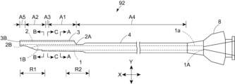
- Fig. 1 is a side view of a catheter according to a first embodiment.
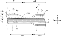
- Fig. 2 is a longitudinal cross-sectional view of region R1 in Fig. 1.
- Fig. 3 is a longitudinal cross-sectional view of region R2 in Fig. 1.
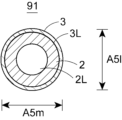
- Fig. 4 is a cross-sectional view A-A of the catheter in Fig. 1.
- Fig. 5 is a cross-sectional view B-B of the catheter in Fig. 1.
- Fig. 6 is a cross-sectional view C-C of the catheter in Fig. 1.
- Fig. 7 is a cross-sectional view D-D of the catheter in Fig. 1.
- Fig. 1 is a side view of a catheter according to a first embodiment.
- Fig. 2 is a longitudinal cross-sectional view of region R1 in Fig. 1.
- Fig. 3 is a longitudinal cross-sectional view of region R2 in Fig. 1.
- Fig. 4 is a cross-sectional view A-
- FIG. 8 is a cross-sectional view E-E of the catheter in Fig. 1.
- Fig. 9 is a longitudinal cross-sectional view of region R2 in a modified version of the catheter in Fig. 1.
- Fig. 16 is a cross-sectional view of a modified version of the catheter in Fig. 5.
- the catheter according to the first embodiment is a catheter 91 having a first tubular member 1 extending in the longitudinal direction X and a second tubular member 2 extending in the longitudinal direction X and adjacent to the first tubular member 1 in the radial direction Y.
- the outer surface of the first tubular member 1 and the outer surface of the second tubular member 2 are adjacent to each other in the radial direction Y.
- the first tubular member 1 has an inner lumen 1L extending in the longitudinal direction X.
- the second tubular member 2 has an inner lumen 2L extending in the longitudinal direction X.
- the catheter 91 By inserting, for example, a guide wire into each of the inner lumen 1L and the inner lumen 2L, the catheter 91 can be guided in multiple directions, making it easier to insert the catheter 91 into various branching parts of the coronary artery, for example. In addition, it is easier to search for the entrance of a stenosis, which is a lesion, by inserting a search wire into the inner lumen 1L or the inner lumen 2L. Of these, it is preferable to insert a probing wire into the lumen 1L. The tip of the probing wire may be bent.
- the first tubular member 1 and the second tubular member 2 each preferably have one or more layers extending in the longitudinal direction X, and more preferably have multiple layers.
- the multiple layers preferably have an inner layer and an outer layer that contains at least a part of the inner layer.
- the multiple layers may further have an intermediate layer located between the inner layer and the outer layer.
- the number of intermediate layers is not limited to one, and may be two or more. It is preferable that each of the multiple layers contains a material different from that of the adjacent layer.
- the inner layer of the first tubular member 1 and the inner layer of the second tubular member 2 each preferably contain at least one resin selected from the group consisting of polyolefin resins and fluorine-based resins.
- the polyolefin resin is preferably polyethylene, polypropylene, an ethylene-propylene copolymer, or a mixture thereof.
- the polyethylene is preferably high-density polyethylene with a specific gravity of 0.942 or more.
- the fluororesin is preferably polytetrafluoroethylene, tetrafluoroethylene-perfluoroalkylvinylether copolymer, tetrafluoroethylene-hexafluoropropylene copolymer, tetrafluoroethylene-ethylene copolymer, polyvinylidene fluoride, polychlorotrifluoroethylene, ethylene-chlorotrifluoroethylene copolymer, or a mixture thereof.
- the inner layer of the first cylindrical member 1 and the inner layer of the second cylindrical member 2 may each contain at least one selected from the group consisting of polyamide resin, polyester resin, polyurethane resin, polyolefin resin, fluorine resin, vinyl chloride resin, silicone resin, and natural rubber.
- the inner layer of the first cylindrical member 1 and the inner layer of the second cylindrical member 2 may contain different resins, preferably the same resin, and more preferably the same resin.
- the outer layer of the first tubular member 1 and the outer layer of the second tubular member 2 each preferably contain a flexible resin.
- the outer layers contain a flexible resin, which makes it easier for the catheter 91 to bend.
- the flexible resin preferably contains at least one type selected from the group consisting of polyethylene, polyurethane, polyurethane-based thermoplastic elastomer, styrene-based thermoplastic elastomer, polyamide elastomer, and polyamide, and more preferably contains at least one type selected from the group consisting of polyurethane and polyamide elastomer.
- the polyethylene is preferably a low-density polyethylene with a specific gravity of 0.91 to 0.92.
- the Shore D hardness of the material of the outer layer is preferably smaller than or equal to the Shore D hardness of the material of the inner layer, and is preferably smaller. This makes the catheter 91 easier to bend.
- the Shore D hardness may be measured, for example, using a durometer type D in accordance with ISO 7619.
- the intermediate layer preferably contains a different material than the inner or outer layer, but may contain the same material as the inner or outer layer.
- the inner layer, middle layer, and outer layer are preferably fixed to the adjacent layers. This makes it difficult for each layer to twist or kink. Examples of the manner of fixing include welding and adhesion. Although not shown, a reinforcing member may be disposed as the middle layer.
- the first tubular member 1 is preferably provided with a reinforcing member. This makes it easier to prevent the wire from breaking through the first tubular member 1.
- the second tubular member 2 is preferably not provided with a reinforcing member. This makes it easier to improve the flexibility of the second tubular member 2.
- the reinforcing member is preferably a braided body in which wire is braided, a coil body in which wire is wound in a spiral shape, or a combination of these. This makes it easier to prevent the wire from breaking through the first tubular member 1. Of these, the braided body is more preferable because it is easier to improve the rigidity.
- wires contained in the reinforcing member include metal wires and fibers.
- the metal wire preferably contains stainless steel, titanium, nickel-titanium alloy, cobalt-chromium alloy, tungsten alloy, or an alloy thereof. Of these, stainless steel is more preferable.
- the metal wire may be a single wire or a twisted wire.
- the distal end of the reinforcing member is preferably located closer to the proximal end of the first opening 1E and more preferably closer to the proximal end 2A of the second tubular member 2.
- the proximal end of the reinforcing member is preferably located closer to the proximal end 2A of the second tubular member 2, and more preferably located within the handle portion 8. This makes it easier to prevent the wire from breaking through the first tubular member 1.
- the distal end 1B of the first tubular member 1 is located proximal to the distal end 2B of the second tubular member 2. This makes it easier for the catheter 91 to bend in the portion distal to the distal end 1B of the first tubular member 1.
- the proximal end 1A of the first tubular member 1 is located proximal to the proximal end 2A of the second tubular member 2.
- the catheter 91 has an outer member 3 that extends in the longitudinal direction X and has a portion that contains at least a portion of the first tubular member 1 and at least a portion of the second tubular member 2.
- the outer member 3 can protect the first tubular member 1 and the second tubular member 2, and can also make it easier to prevent the wire from breaking through from inside the catheter 91.
- the outer member 3 preferably contains at least one selected from the group consisting of polyethylene, polyurethane, polyurethane-based thermoplastic elastomer, styrene-based thermoplastic elastomer, polyamide elastomer, and polyamide. Of these, at least one selected from the group consisting of polyurethane and polyamide elastomer is more preferable.
- the outer member 3 has a first region A1 extending in the longitudinal direction X distally from the proximal end 2A of the second tubular member 2, and a second region A2 extending in the longitudinal direction X and located distally of the first region A1.
- the ratio of the major axis A1l to the minor axis A1m in the cross section of the first region A1 in the radial direction Y is 1.0 to 1.1.
- the ratio of the major axis A2l to the minor axis A2m in the cross section of the second region A2 in the radial direction Y is 1.2 to 2.0.
- the catheter 91 Since the major axis A1l/minor axis A1m value of the first region A1 is 1.0 to 1.1, the catheter 91 is less likely to twist in meandering parts of the body, making it easier to transmit forces from the proximal side to the distal side. On the other hand, by setting the value of the major axis A2l/minor axis A2m of the second region A2 distal to the first region A1 to 1.2 to 2.0, the catheter 91 can be easily curved along the shape of the meandering part in the body.
- the value of the major axis A2l/minor axis A2m is preferably 1.2 to 1.9, more preferably 1.2 to 1.7, and even more preferably 1.2 to 1.5.
- the outer member 3 only needs to have the first region A1 distal to the proximal end 2A of the second cylindrical member 2, and the first region A1 may be located distal to the proximal end 2A of the second cylindrical member 2.
- the length of the major axis A1l of the first region A1 is preferably 0.5 mm or more and 2.0 mm or less, and more preferably 0.7 mm or more and 1.6 mm or less.
- the major axis of each region in the radial Y cross section refers to the length of the longest line segment that connects two points on the outer edge of each region in the radial Y cross section and passes through the centroid. If the cross section is a part of an ellipse, as described below, the major axis of the circumscribing imaginary ellipse is the major axis in the radial Y cross section.
- the minor axis of each region in the radial Y cross section refers to the length of the shortest line segment that connects two points on the outer edge of each region in the radial Y cross section and passes through the centroid.
- the minor axis of the circumscribing imaginary ellipse is the minor axis in the radial Y cross section. If the outer edge of the radial Y cross section is a circle, the major and minor axes are the same length.
- the shape of the outer edge A1e in the cross section in the radial direction Y of the first region A1 is preferably a circle or an ellipse, and more preferably a circle. This makes it difficult for the first region A1 to twist in meandering parts inside the body, making it easier for the catheter 91 to transmit force from the proximal side to the distal side.
- the shape of the outer edge A1e in the cross section in the radial direction Y of the first region A1 may be a rounded polygon or the like.
- the first region A1 may have parts whose cross-sectional shapes in the radial direction Y are different from each other.
- the shape of the outer edge A2e in the cross section in the radial direction Y of the second region A2 is preferably an ellipse. This allows the second region A2 to bend easily along the shape of the meandering part inside the body, and the catheter 91 to bend easily along the shape of the meandering part inside the body.
- the shape of the outer edge A2e in the cross section in the radial direction Y of the second region A2 is preferably a partial ellipse.
- the partial ellipse shape is the shape after a part of the ellipse is cut out.
- the shape of the outer edge A2e in the cross section in the radial direction Y of the second region A2 may be a rounded polygon or the like.
- the second region A2 may have parts whose cross-sectional shapes in the radial direction Y are different from each other.
- the area of the region surrounded by the outer edge A1e in the radial Y cross section of the first region A1 is preferably larger than or equal to the area of the region surrounded by the outer edge A2e in the radial Y cross section of the second region A2, and more preferably larger. This makes it easier to insert the catheter 91 into a tortuous portion of the body.
- the area of the region surrounded by the outer edge A1e in the radial Y cross section of the first region A1 is preferably 1.00 times or more and 2.00 times or less, and more preferably 1.01 times or more and 1.50 times or less, of the area of the region surrounded by the outer edge A2e in the radial Y cross section of the second region A2.
- the major axis A2l of the second region A2 is preferably larger than or equal to the major axis A1l of the first region A1, and more preferably larger than the major axis A1l of the first region A1. This makes it easier for the second region A2 to transmit force from the proximal side to the distal side.
- the major axis A2l of the second region A2 may be smaller than the major axis A1l of the first region A1. In this case, the flexibility of the second region A2 is improved.
- the shortest distance in the radial direction Y from the outer edge A2e of the second region A2 of the outer member 3 to the outer edge 1e of the first tubular member 1 is preferably longer than or equal to the shortest distance from the outer edge A1e of the first region A1 of the outer member 3 to the outer edge 1e of the first tubular member 1, and more preferably longer than the shortest distance from the outer edge A1e to the outer edge 1e.
- the shortest distance in the second region A2 is measured in a portion of the second region A2 whose cross-sectional shape in the radial direction Y is an ellipse. The same applies to the shortest distance in the second region A2 below.
- the shortest distance from the outer edge A2e of the second region A2 of the outer member 3 to the outer edge 1e of the first tubular member 1 may be shorter than the shortest distance from the outer edge A1e of the first region A1 of the outer member 3 to the outer edge 1e of the first tubular member 1.
- the second region A2 in the vicinity of the first tubular member 1 is less likely to twist when inserted into the serpentine portion.
- the shortest distance from the outer edge A2e of the second region A2 of the outer member 3 to the outer edge 2e of the second tubular member 2 is preferably longer than or equal to the shortest distance from the outer edge A1e of the first region A1 of the outer member 3 to the outer edge 2e of the second tubular member 2, and more preferably longer than the shortest distance from the outer edge A1e to the outer edge 2e.
- the shortest distance in the second region A2 is measured in a portion of the second region A2 whose cross-sectional shape in the radial direction Y is an ellipse. The same applies to the shortest distance in the second region A2 below.
- the shortest distance from the outer edge A2e of the second region A2 of the outer member 3 to the outer edge 2e of the second tubular member 2 may be shorter than the shortest distance from the outer edge A1e of the first region A1 of the outer member 3 to the outer edge 2e of the second tubular member 2.
- the second region A2 in the vicinity of the second tubular member 2 is less likely to twist when inserted into the serpentine portion.
- the length of the second region A2 in the longitudinal direction X is shorter than the length of the first region A1 in the longitudinal direction X. This makes it easier to insert the catheter 91 into a tortuous portion of the body.
- the length of the first region A1 in the longitudinal direction X is 1.1 times or more and 30 times or less, and more preferably 1.2 times or more and 20 times or less, of the length of the second region A2 in the longitudinal direction X.
- the outer member 3 has a third region A3 between the first region A1 and the second region A2 in the longitudinal direction X, and it is preferable that the ratio of the major axis A3l to the minor axis A3m in the cross section of the third region A3 in the radial direction Y is greater than 1.1 and less than 1.2.
- the third region A3 makes it easier to avoid bending due to a sudden change in shape between the first region A1 and the second region A2. Therefore, it is more preferable that the first region A1 and the third region A3 are adjacent to each other in the longitudinal direction X, and that the third region A3 and the second region A2 are adjacent to each other in the longitudinal direction X.
- the length of the third region A3 in the longitudinal direction X is preferably 1 mm or more and 20 mm or less, and more preferably 3 mm or more and 10 mm or less.
- the value of major axis A3l/minor axis A3m of the third region A3 decreases from the proximal side to the distal side. This makes it easier to avoid bending due to the sudden change in shape between the first region A1 and the second region A2. It is preferable that the shape of the outer edge A3e of the third region A3 in the cross section in the radial direction Y is elliptical. This makes it easier to achieve the above-mentioned effects.
- the shape of the outer edge A3e of the third region A3 in the cross section in the radial direction Y may be a rounded polygon or the like.
- the distal end 3B of the outer member 3 is located distal to the distal end 2B of the second tubular member 2.
- At least a portion of the inner surface of the outer member 3 is fixed to the outer surfaces of the first tubular member 1 and the second tubular member 2. This makes it difficult for the outer member 3 to twist or twist. Examples of the manner of fixing include welding, adhesion, etc.
- the length in the longitudinal direction X from the distal end 3B of the outer member 3 to the distal end 2B of the second tubular member 2 is preferably greater than the maximum thickness of the second tubular member 2. This improves the flexibility of the catheter 91 near its distal end.
- the outer surfaces of the first tubular member 1 and the second tubular member 2 may not be in contact with each other, or may be in contact with each other and fixed.
- Examples of the fixing method include welding, adhesion, etc.
- the outer surface of the first tubular member 1 and the outer surface of the second tubular member 2 are not in contact with each other, they are preferably fixed to each other via the resin of the outer member 3.
- the shapes of the first lumen 1L and the second lumen 2L are preferably circular, elliptical, arched, or a combination of these, and more preferably circular or elliptical.
- the catheter 91 it is preferable that the first lumen 1L and the second lumen 2L are not connected to each other. In the cross section of the radial direction Y, the first lumen 1L may have a larger area than the second lumen 2L, may have a smaller area than the second lumen 2L, or may have the same area as the second lumen 2L.
- the first tubular member 1 preferably has a first opening 1E that communicates with the inner cavity 1L.
- the first opening 1E can be used as an entrance or exit for the wire.
- the second tubular member 2 preferably has a second opening 2E that communicates with the inner cavity 2L.
- the second opening 2E can be used as an entrance or exit for the wire.
- the outer member 3 preferably has a protuberance 34 that protrudes away from the central axis 2C on the side closer to the first tubular member 1 in the radial direction Y than the distal end 1B of the first tubular member 1. This allows the tip of the wire inserted into the first tubular member 1 to be guided in a different direction from the tip of the wire inserted into the second tubular member 2, making it easier to treat bifurcation lesions, etc. This also makes it harder for the wires to become entangled.
- the protuberance 34 is preferably adjacent to the distal end 1B of the first tubular member 1. This makes it easier to guide the wire coming out of the first opening 1E by the protuberance 34.
- the protuberance 34 has a first inclined portion inclined in a direction away from the central axis 2C as it approaches the distal side, and a second inclined portion inclined so as to approach the central axis 2C as it approaches the distal side. It is preferable that the second inclined portion is located more distal than the first inclined portion. The first inclined portion makes it easier to guide the wire coming out of the first opening 1E. The second inclined portion makes it easier to insert into the body.
- the shape of the outer surface of the first inclined portion and the second inclined portion in the cross section X is preferably linear or curved, and more preferably linear.
- the shape of the second inclined portion in the cross section X is linear, the shape of the second inclined portion is a so-called tapered shape.
- the second tubular member 2 may not have a protruding portion that protrudes away from the central axis 2C on the side distal to the distal end 1B of the first tubular member 1 and closer to the first tubular member 1 in the radial direction Y. This reduces the outer diameter of the catheter 91 by the amount of the protruding portion, making it easier for the catheter 91 to bend.
- the outer diameters of the first tubular member 1 and the second tubular member 2 are preferably 0.2 mm or more and 0.8 mm or less, and more preferably 0.3 mm or more and 0.7 mm or less. This makes it easier to insert the catheter 91 into the tortuous portion of the coronary artery.
- a handle portion 8 is preferably disposed at the proximal end 1a of the first tubular member 1.
- the proximal end 1a of the first tubular member 1 is preferably disposed within the handle portion 8.
- the practitioner can insert the catheter 91 into the body by grasping and pushing the handle portion 8.
- the outer shape of the handle portion 8 may be such that the practitioner can grasp it with his/her fingers.
- the handle portion 8 is preferably a resin molded product obtained by injection molding or the like. Examples of resins include polyolefin resins such as polyethylene and polypropylene, polycarbonate resins, and (meth)acrylic resins. Of these resins, transparent resins such as polycarbonate and polymethyl methacrylate are preferred. This makes it easier to see inside the handle portion 8, making it easier to insert the wire.
- the proximal end 1A of the first tubular member 1 is preferably located within the handle portion 8. This improves pushability.
- the handle portion 8 preferably has an inner cavity that communicates with the inner cavity 1L of the first tubular member 1 and extends in the longitudinal direction X, and a wire can be inserted through this inner cavity.
- the catheter 91 preferably further has an outer tubular member 4 extending in the longitudinal direction X.
- the outer tubular member 4 preferably has an inner cavity 4L extending in the longitudinal direction X, and a part of the first tubular member 1 is preferably disposed in the inner cavity 4L.
- the outer tubular member 4 can form a double tube structure (coaxial structure), which can improve the transmission of the pushing force while protecting the first tubular member 1.
- the outer tubular member 4 preferably has a fixed part fixed to the first tubular member 1 at the distal end and a non-fixed part not fixed to the first tubular member 1 on the proximal side of the fixed part. The non-fixed part can make it easier to release the force associated with the insertion of the wire into the first tubular member 1.
- the non-fixed part is longer than the fixed part in the longitudinal direction X. This can reduce the risk of the wire breaking through the first tubular member 1.
- the outer tubular member 4 preferably has a fixed part fixed to the handle part 8 at the proximal end.
- the outer tubular member 4 is preferably located proximal to the proximal end 2A of the second tubular member 2. This allows the outer diameter of the outer tubular member 4 to be reduced.
- the outer tubular member 4 preferably contains the same resin as the outer member 3 or a harder resin, and more preferably is made of a harder resin. A harder resin can improve pushability.
- the distal end of the outer tubular member 4 and the proximal end of the outer member 3 are preferably fixed to each other.
- the outer tubular member 4 has a fourth region A4 extending in the longitudinal direction X from the proximal end 2A of the second tubular member 2 to the proximal side, and the ratio of the major axis A4l to the minor axis A4m in the cross section of the fourth region A4 in the radial direction Y is preferably 1.0 to 1.1.
- major axis A4l/minor axis A4m be 1.0 to 1.1, the catheter 91 is less likely to twist in meandering parts of the body, making it easier to transmit force from the proximal side to the distal side.
- the outer tubular member 4 may have a fourth region A4 proximal to the proximal end 2A of the second tubular member 2, and the fourth region A4 may be located proximal to the proximal end 2A of the second tubular member 2.
- the major axis A2l of the second region A2 is smaller than the major axis A4l of the fourth region A4. This makes it easier for the second region A2 to bend in meandering areas within the body. It is preferable that the major axis A2l is 0.99 times or less, and more preferably 0.98 times or less, of the major axis A4l. On the other hand, it is preferable that the major axis A2l is 0.5 times or more, and more preferably 0.6 times or more, of the major axis A4l. This can improve the pushability of the second region A2.
- the length of the fourth region A4 in the longitudinal direction X is longer than the sum of the length of the first region A1 in the longitudinal direction X and the length of the second region A2 in the longitudinal direction X.
- the length of the fourth region A4 is preferably at least twice the sum of the lengths of the first region A1 and the second region A2, and more preferably at least three times. Meanwhile, this ratio is preferably 14 times or less, and more preferably 6 times or less. This can reduce the length of the catheter 91.
- the sum of the lengths of the first region A1 and the second region A2 in the longitudinal direction X is preferably 5 cm or more and 50 cm or less, and more preferably 10 cm or more and 40 cm or less.
- the outer member 3 has a fifth region A5 extending in the longitudinal direction X and located distal to the second region A2.
- the ratio of the major axis A5l to the minor axis A5m in the radial cross section of the fifth region A5 is preferably 1.0 to 1.1.
- the fifth region A5 includes the distal end of the catheter 91.
- the fifth region A5 is adjacent to the second region A2 in the longitudinal direction X, but other regions may exist between the fifth region A5 and the second region A2.
- the ratio of the major axis to the minor axis of the other regions in the radial cross section Y is preferably greater than 1.1 and less than 1.2. This makes it easier to avoid bending due to sudden shape changes.
- the outer member 3 preferably has a columnar body 5 extending in the longitudinal direction X and containing resin, and at least a part of the first cylindrical member 1 and at least a part of the second cylindrical member 2 are disposed within the columnar body 5. That is, at least a part of the first cylindrical member 1 and the second cylindrical member 2 are preferably sealed by the columnar body 5 extending in the longitudinal direction X and containing resin. This makes it easier to maintain the shapes of the lumen 1L and the lumen 2L extending in the longitudinal direction X even if the catheter 91 is curved.
- the columnar body 5 has at least the first region A1 and the second region A2, and further has a third region A3 and/or a fifth region A5.
- the resin of the columnar body 5 may be present between the first cylindrical member 1 and the second cylindrical member 2.
- the cylinder 5 preferably has an elliptical cylindrical portion, a cylindrical portion, or an elliptical cylindrical portion and a cylindrical portion. It is more preferable that the cylinder 5 has a plurality of elliptical cylindrical portions with different major axis/minor axis values. It is preferable that the plurality of elliptical cylindrical portions are adjacent to each other in the longitudinal direction X. Each elliptical cylindrical portion may be a portion with a constant major axis/minor axis value, or a portion with a change in major axis/minor axis value toward the distal side. Furthermore, when the cylinder 5 has an elliptical cylindrical portion and a cylindrical portion, it is preferable that the elliptical cylindrical portion and the cylindrical portion are adjacent to each other in the longitudinal direction X.
- the columnar body 5 can be formed, for example, by arranging two or more tubes with different major axis/minor axis values side by side in the longitudinal direction X, placing the first cylindrical member 1 and the second cylindrical member 2 inside these tubes while overlapping them in the radial direction Y, and heating and fusing these tubes to the first cylindrical member 1 and the second cylindrical member 2.
- the columnar body 5 can be formed by preparing a tube with a major axis/minor axis value of 1.0 to 1.1, placing the first cylindrical member 1 and the second cylindrical member 2 inside the tube while overlapping them in the radial direction Y, and fusing the tube to the first cylindrical member 1 and the second cylindrical member 2 while heating the tube and sandwiching a part of the tube with plates or the like from both sides in the radial direction toward the inside.
- the second region A2 can also be formed by setting the major axis/minor axis value of the part sandwiched by the plates or the like to 1.2 to 2.0. The same applies to the other regions.
- the first tubular member 1 may have an X-ray opaque marker 6A proximal to the proximal end of the first opening 1E and distal to a point 1 cm proximally away from the proximal end of the first opening 1E. This makes it easier to grasp the position of the first opening 1E.
- the second tubular member 2 may have an X-ray opaque marker 6B at a position distal to the distal end 1B of the first tubular member 1 and proximal to the distal end 2B of the second tubular member 2. This makes it easier to grasp the position of the curved part of the catheter 91 when inserting the catheter 91 into a tortuous part inside the body, making insertion easier.
- the radiopaque marker is preferably ring-shaped.
- the radiopaque marker preferably contains a radiopaque material, and more preferably consists of a radiopaque material.
- the radiopaque material is preferably at least one selected from the group consisting of lead, barium, iodine, tungsten, gold, platinum, iridium, platinum-iridium alloy, stainless steel, titanium, cobalt-chromium alloy, palladium, bismuth, and tantalum.
- the catheter 91 extends in the longitudinal direction X, is disposed within at least the first region A1 and the fourth region A4, and has a linear member 11 whose distal end 11B is located within the first region A1. This can improve pushability.
- the linear member 11 preferably contains a metal, and more preferably is made of a metal.
- the metal is preferably stainless steel, nickel titanium, cobalt chrome, or an alloy thereof. This can further improve pushability.
- the linear member 11 is preferably linear in shape.
- the linear member 11 is preferably a solid member that does not have an internal cavity. This can further improve pushability.
- the number of linear members 11 in the catheter 91 may be one, or two or more.
- the linear member 11 has a constant diameter section 11U that extends in the longitudinal direction X and has a constant radial length. It is more preferable that the linear member 11 further has a tapered section 11T that is located distal to the constant diameter section 11U and that tapers toward the distal side.
- the proximal end of the linear member 11 is preferably located within the handle portion 8.
- the proximal end of the linear member 11 is preferably fixed to the first tubular member 1, the handle portion 8, or the outer tubular member 4. This can further improve pushability.
- the catheter 91 may further have a tip extending in the longitudinal direction X. It is preferable that the tip has an inner cavity extending in the longitudinal direction X, and that at least the distal end of the second tubular member 2 is disposed within the inner cavity. This makes it easier for the tip and the second tubular member 2 to bend integrally.
- At least a portion of the inner surface of the tip is fixed to the outer surface of the second tubular member 2. This makes it easier for the tip and the second tubular member 2 to bend as a unit. Examples of the manner of fixing include welding, adhesion, etc.
- the chip preferably contains a flexible resin.
- the flexible resin preferably contains at least one selected from the group consisting of polyethylene, polyurethane, polyurethane-based thermoplastic elastomer, styrene-based thermoplastic elastomer, polyamide elastomer, and polyamide, and more preferably contains at least one selected from the group consisting of polyurethane and polyamide elastomer.
- the polyethylene is preferably a low-density polyethylene having a specific gravity of 0.91 to 0.92.
- the tip has a region in which the ratio of the major axis to the minor axis in a cross section in the radial direction Y is 1.0 to 1.1. It is preferable that this region includes the distal end of the tip. This makes it easier to prevent deformation, such as twisting, of the distal end of the tip. It is more preferable that the tip consists of this region.
- the catheter 91 can be preferably used to treat narrowing or dilating blocked areas of blood vessels and other passageways in the body, and can be preferably used in performing coronary intervention (PCI) for lesions at the bifurcation of coronary arteries, etc.
- PCI coronary intervention
- Figure 10 is a side view of a catheter according to the second embodiment.
- Figure 11 is a longitudinal cross-sectional view of region R1 in Figure 10.
- Figure 12 is a longitudinal cross-sectional view of region R2 in Figure 10.
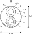
- Figure 13 is a cross-sectional view of the catheter in Figure 10 taken along line A-A.
- Figure 14 is a cross-sectional view of the catheter in Figure 10 taken along line B-B.
- Figure 15 is a cross-sectional view of the catheter in Figure 10 taken along line C-C.
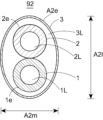
- the catheter according to the second embodiment is a catheter 92 having a first tubular member 1 extending in the longitudinal direction X, a second tubular member 2 extending in the longitudinal direction X and adjacent to the first tubular member 1 in the radial direction Y, and an outer member 3 extending in the longitudinal direction X and having a portion that contains at least a portion of the first tubular member 1 and at least a portion of the second tubular member 2.
- a catheter 92 having a first tubular member 1 extending in the longitudinal direction X, a second tubular member 2 extending in the longitudinal direction X and adjacent to the first tubular member 1 in the radial direction Y, and an outer member 3 extending in the longitudinal direction X and having a portion that contains at least a portion of the first tubular member 1 and at least a portion of the second tubular member 2.
- the outer member 3 is cylindrical and has a lumen 3L extending in the longitudinal direction X, and it is preferable that at least a part of the first cylindrical member 1 and at least a part of the second cylindrical member 2 are disposed in the lumen 3L.
- This makes it possible to protect the first cylindrical member 1 and the second cylindrical member 2, and also allows each cylindrical member to move to some extent due to the gap between the outer member 3 and the first cylindrical member 1 and the gap between the outer member 3 and the second cylindrical member 2, so that the force of the wire can be released from inside the catheter 92. As a result, it is possible to easily prevent the wire from breaking through.
- the distal end of the cylindrical outer member 3 is preferably fixed to the first cylindrical member 1 and the second cylindrical member 2.
- the proximal end of the cylindrical outer member 3 is preferably fixed to the first cylindrical member 1 and the second cylindrical member 2. This makes it difficult for the cylindrical outer member 3 to twist or twist. Examples of the fixing method include welding and adhesion.
- the first region A1 and second region A2 of the cylindrical outer member 3 can be formed, for example, by joining two or more tubes with different major axis/minor axis values in the longitudinal direction X.
- a tube with a major axis/minor axis value of 1.0 to 1.1 can be prepared, and the second region A2 with a major axis/minor axis value of 1.2 to 2.0 can be formed by heating a portion of the tube and sandwiching it between plates or the like from both radial sides toward the inside while heating it. The same applies to the other regions.
- the cylindrical outer member 3 has at least a first region A1 and a second region A2, and more preferably has a third region A3 and/or a fifth region A5.
- first region A1 and a second region A2 and more preferably has a third region A3 and/or a fifth region A5.
- the first tubular member 1 and the second tubular member 2 are preferably fixed to each other in the radial direction Y.
- the outer surface of the first tubular member 1 and the outer surface of the second tubular member 2 are preferably fixed to each other in the radial direction Y. This makes the first tubular member 1 and the second tubular member 2 less likely to twist or distort. Examples of the manner of fixing include welding, adhesion, etc.
Landscapes
- Health & Medical Sciences (AREA)
- Life Sciences & Earth Sciences (AREA)
- Biophysics (AREA)
- Pulmonology (AREA)
- Engineering & Computer Science (AREA)
- Anesthesiology (AREA)
- Biomedical Technology (AREA)
- Heart & Thoracic Surgery (AREA)
- Hematology (AREA)
- Animal Behavior & Ethology (AREA)
- General Health & Medical Sciences (AREA)
- Public Health (AREA)
- Veterinary Medicine (AREA)
- Media Introduction/Drainage Providing Device (AREA)
Priority Applications (2)
| Application Number | Priority Date | Filing Date | Title |
|---|---|---|---|
| JP2025537797A JPWO2025028186A1 (https=) | 2023-08-01 | 2024-07-09 | |
| CN202480043377.7A CN121419807A (zh) | 2023-08-01 | 2024-07-09 | 导管 |
Applications Claiming Priority (2)
| Application Number | Priority Date | Filing Date | Title |
|---|---|---|---|
| JP2023-125557 | 2023-08-01 | ||
| JP2023125557 | 2023-08-01 |
Publications (1)
| Publication Number | Publication Date |
|---|---|
| WO2025028186A1 true WO2025028186A1 (ja) | 2025-02-06 |
Family
ID=94395146
Family Applications (1)
| Application Number | Title | Priority Date | Filing Date |
|---|---|---|---|
| PCT/JP2024/024770 Pending WO2025028186A1 (ja) | 2023-08-01 | 2024-07-09 | カテーテル |
Country Status (3)
| Country | Link |
|---|---|
| JP (1) | JPWO2025028186A1 (https=) |
| CN (1) | CN121419807A (https=) |
| WO (1) | WO2025028186A1 (https=) |
Citations (2)
| Publication number | Priority date | Publication date | Assignee | Title |
|---|---|---|---|---|
| WO2020255736A1 (ja) * | 2019-06-19 | 2020-12-24 | 株式会社カネカ | カテーテル、及びカテーテルの製造方法 |
| JP2023004052A (ja) * | 2021-06-25 | 2023-01-17 | 朝日インテック株式会社 | カテーテル |
-
2024
- 2024-07-09 JP JP2025537797A patent/JPWO2025028186A1/ja active Pending
- 2024-07-09 CN CN202480043377.7A patent/CN121419807A/zh active Pending
- 2024-07-09 WO PCT/JP2024/024770 patent/WO2025028186A1/ja active Pending
Patent Citations (2)
| Publication number | Priority date | Publication date | Assignee | Title |
|---|---|---|---|---|
| WO2020255736A1 (ja) * | 2019-06-19 | 2020-12-24 | 株式会社カネカ | カテーテル、及びカテーテルの製造方法 |
| JP2023004052A (ja) * | 2021-06-25 | 2023-01-17 | 朝日インテック株式会社 | カテーテル |
Also Published As
| Publication number | Publication date |
|---|---|
| CN121419807A (zh) | 2026-01-27 |
| JPWO2025028186A1 (https=) | 2025-02-06 |
Similar Documents
| Publication | Publication Date | Title |
|---|---|---|
| AU2002354761B2 (en) | Torqueable soft tip medical device and method of usage | |
| JP4547374B2 (ja) | アンバランスな補強部材を含む医療用装置及びその製造方法 | |
| KR102315805B1 (ko) | 대형 루멘 안내 카테터 | |
| AU2002354761A1 (en) | Torqueable soft tip medical device and method of usage | |
| JPWO2020162287A1 (ja) | 延長カテーテル、及びその製造方法 | |
| CN115666698B (zh) | 导管 | |
| JP7444879B2 (ja) | カテーテル、及びカテーテルの製造方法 | |
| JPWO2020162286A1 (ja) | 延長カテーテル、及びその製造方法 | |
| WO2022158418A1 (ja) | カテーテル | |
| CN113993569B (zh) | 导管 | |
| WO2025028186A1 (ja) | カテーテル | |
| JP2025023674A (ja) | カテーテル | |
| JP2025023675A (ja) | カテーテル | |
| WO2025033067A1 (ja) | カテーテル | |
| WO2025028183A1 (ja) | カテーテル | |
| WO2025028184A1 (ja) | カテーテル | |
| WO2025028185A1 (ja) | カテーテル | |
| WO2025197466A1 (ja) | カテーテル | |
| JP7738429B2 (ja) | カテーテル | |
| JP7693332B2 (ja) | カテーテル | |
| CN216022317U (zh) | 一种造影导丝 | |
| WO2022158417A1 (ja) | カテーテル | |
| WO2025204939A1 (ja) | カテーテル及びカテーテルの製造方法 | |
| JP2024012725A (ja) | カテーテル | |
| JP2018201575A (ja) | カテーテルおよびその製造方法 |
Legal Events
| Date | Code | Title | Description |
|---|---|---|---|
| 121 | Ep: the epo has been informed by wipo that ep was designated in this application |
Ref document number: 24848845 Country of ref document: EP Kind code of ref document: A1 |
|
| ENP | Entry into the national phase |
Ref document number: 2025537797 Country of ref document: JP Kind code of ref document: A |
|
| WWE | Wipo information: entry into national phase |
Ref document number: 2025537797 Country of ref document: JP |
|
| NENP | Non-entry into the national phase |
Ref country code: DE |