WO2025028087A1 - 防振具及び防振具を有するモータ - Google Patents
防振具及び防振具を有するモータ Download PDFInfo
- Publication number
- WO2025028087A1 WO2025028087A1 PCT/JP2024/023079 JP2024023079W WO2025028087A1 WO 2025028087 A1 WO2025028087 A1 WO 2025028087A1 JP 2024023079 W JP2024023079 W JP 2024023079W WO 2025028087 A1 WO2025028087 A1 WO 2025028087A1
- Authority
- WO
- WIPO (PCT)
- Prior art keywords
- metal ring
- vibration isolator
- motor
- rubber material
- elastic body
- Prior art date
- Legal status (The legal status is an assumption and is not a legal conclusion. Google has not performed a legal analysis and makes no representation as to the accuracy of the status listed.)
- Pending
Links
Images










Classifications
-
- F—MECHANICAL ENGINEERING; LIGHTING; HEATING; WEAPONS; BLASTING
- F16—ENGINEERING ELEMENTS AND UNITS; GENERAL MEASURES FOR PRODUCING AND MAINTAINING EFFECTIVE FUNCTIONING OF MACHINES OR INSTALLATIONS; THERMAL INSULATION IN GENERAL
- F16F—SPRINGS; SHOCK-ABSORBERS; MEANS FOR DAMPING VIBRATION
- F16F15/00—Suppression of vibrations in systems; Means or arrangements for avoiding or reducing out-of-balance forces, e.g. due to motion
- F16F15/02—Suppression of vibrations of non-rotating, e.g. reciprocating systems; Suppression of vibrations of rotating systems by use of members not moving with the rotating systems
- F16F15/04—Suppression of vibrations of non-rotating, e.g. reciprocating systems; Suppression of vibrations of rotating systems by use of members not moving with the rotating systems using elastic means
- F16F15/08—Suppression of vibrations of non-rotating, e.g. reciprocating systems; Suppression of vibrations of rotating systems by use of members not moving with the rotating systems using elastic means with rubber springs ; with springs made of rubber and metal
-
- H—ELECTRICITY
- H02—GENERATION; CONVERSION OR DISTRIBUTION OF ELECTRIC POWER
- H02K—DYNAMO-ELECTRIC MACHINES
- H02K5/00—Casings; Enclosures; Supports
- H02K5/24—Casings; Enclosures; Supports specially adapted for suppression or reduction of noise or vibrations
Definitions
- This disclosure relates to vibration isolators and motors having vibration isolators.
- Motors are used in a variety of appliances, including household electrical appliances such as air conditioners and washing machines.
- motors are used as fan motors mounted in the indoor or outdoor units of air conditioners.
- Motors mounted in the indoor or outdoor units of air conditioners have fans, such as centrifugal fans or crossflow fans, attached to the tip of the rotating shaft that protrudes on both sides or one side of the motor.
- the motor is attached to the base of the equipment via a ring-shaped vibration isolator so that vibrations generated by the motor are not transmitted to the outside (see Patent Document 1). This makes it possible to prevent vibrations from the motor from being transmitted to the base. This makes it possible to achieve quieter equipment.
- the ring-shaped vibration isolator is composed of a thin cylindrical elastic body and a metal ring made of an annular metal plate that surrounds the elastic body.
- the vibration isolator is attached, for example, to a bracket on a motor body that has a rotor and a stator.
- a motor with a vibration isolator is fixed to the base by setting the vibration isolator on the motor support part of the base and tightening the vibration isolator with a tightening member.
- the vibration isolator when fixing the motor to the base, the vibration isolator may be over-tightened by the fastening members. In other words, the fastening force of the fastening members may become too great, and the vibration isolator may be tightened to a point where it does not need to be tightened at all.
- the present disclosure has been made to solve such problems.
- the purpose of the present disclosure is to provide a vibration isolator that can prevent excessive tightening force and a motor having the vibration isolator.
- a vibration-damping device comprises an annular elastic body and a metal ring covering the outer peripheral surface of the elastic body, the metal ring having a divided portion in which a portion of the circumferential direction of the metal ring is divided, the elastic body having a recessed portion in which the outer peripheral surface is recessed at the divided portion, and a first end portion, which is one end portion of the circumferential direction of the metal ring, is bent so that its tip is located inside the recessed portion.
- a vibration-damping device that includes an annular elastic body and a metal ring that covers the outer peripheral surface of the elastic body, and has a structure that causes the tightening force that the elastic body receives to differ at two circumferential positions when the elastic body is tightened by the metal ring.
- a motor according to another aspect of the present disclosure includes a vibration isolator according to any of the above aspects, a rotor having a rotating shaft, and a bracket having a protruding portion housing a bearing that supports the rotating shaft, and the vibration isolator is fitted into the protruding portion.
- This disclosure makes it possible to realize a vibration isolator that can prevent excessive tightening force and a motor having the same.
- FIG. 1 is a side view of a motor according to an embodiment.
- FIG. 2 is a side view showing the motor according to the embodiment with the motor body and the vibration isolator separated.
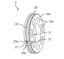
- FIG. 3A is a perspective view of a vibration isolator according to an embodiment.
- FIG. 3B is a perspective view of another vibration isolator according to an embodiment.
- FIG. 4A is a diagram showing a configuration of a vibration isolator according to an embodiment.
- FIG. 4B is a diagram showing the configuration of another vibration isolator according to the embodiment.
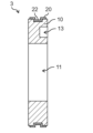
- FIG. 5A is a cross-sectional view of the vibration isolator taken along line VV in FIG. 4A (c).
- FIG. 5B is a cross-sectional view of another vibration isolator according to an embodiment.
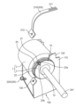
- FIG. 6 is a side view of the motor fixed to the base.
- FIG. 7 is a perspective view of the motor fixed to the base.
- FIG. 8 is a perspective view of the motor showing a state in which the fastening member has been removed from the base.
- FIG. 9 is a diagram for explaining a state in which a motor body is fixed to a base using a vibration isolator of a comparative example.
- FIG. 10 is a side view of the vibration isolator according to the first modification.
- FIG. 11 is an enlarged cross-sectional view of a vibration isolator according to an embodiment.
- FIG. 12 is an enlarged cross-sectional view of a vibration isolator according to the second modification.
- FIG. 13 is an enlarged cross-sectional view of a vibration isolator according to the third modification.
- FIG. 14 is a side view of a vibration isolator according to the fourth modification.
- FIG. 15 is a side view of a vibration isolator according to the fifth modification.
- FIG. 16 is a side view of a vibration isolator according to the sixth modification.
- FIG. 1 Each figure is a schematic diagram and is not necessarily a precise illustration.
- the same reference numerals are used for configurations that are substantially the same as in other figures, and duplicate explanations are omitted or simplified.
- the terms “upper” and “lower” do not necessarily refer to the upper direction (vertically upward) and the lower direction (vertically downward) in an absolute spatial sense.
- Fig. 1 is a side view of the motor 1 according to an embodiment.
- Fig. 2 is a side view showing the motor 1 according to the embodiment with a motor body 2 and a vibration isolator 3 separated from each other.
- the motor 1 includes a motor body 2 and a vibration isolator 3 attached to the motor body 2.
- a vibration isolator 3 attached to the motor body 2.
- two vibration isolators 3 are attached to the motor body 2.
- the motor body 2 comprises a rotor 2a, a stator 2b, a first bearing 2c, a second bearing 2d, a first bracket 2e, and a second bracket 2f.
- the rotor 2a has a rotating shaft 2a1, which is a metallic shaft.
- the stator 2b generates a magnetic force for rotating the rotor 2a.
- the first bearing 2c and the second bearing 2d support the rotating shaft 2a1 so that it can rotate freely.
- the first bracket 2e holds the first bearing 2c.
- the second bracket 2f holds the second bearing 2d.
- the motor body 2 is a brushless motor that does not use brushes.
- the motor body 2 is an inner rotor type motor in which the rotor 2a is arranged inside the stator 2b.
- the motor body 2 is a molded motor.
- the motor body 2 includes molded resin 2g that covers the stator 2b.
- the first bracket 2e, the second bracket 2f, and the molded resin 2g form the outer shell of the motor body 2.
- the first bracket 2e and the second bracket 2f are fixed to the molded resin 2g.
- the first bracket 2e and the second bracket 2f are made of a metal material. Specifically, the first bracket 2e and the second bracket 2f are made of a metal plate. The first bracket 2e and the second bracket 2f are formed into a predetermined shape by performing a press process or the like on the metal plate.
- the first bracket 2e has a protruding portion 2e1 that protrudes outward.
- the protruding portion 2e1 is formed in a circular convex shape so as to protrude to one side in the axial direction of the rotating shaft 2a1.
- the first bearing 2c is housed in the protruding portion 2e1 and fixed to the protruding portion 2e1.
- the second bracket 2f has a protruding portion 2f1 that protrudes outward.
- the protruding portion 2f1 is formed in a circular convex shape so as to protrude to the other side in the axial direction of the rotating shaft 2a1.
- the second bearing 2d is housed in the protruding portion 2f1 and fixed to the protruding portion 2f1.
- the two vibration isolators 3 are attached to both sides of the motor body 2 in the axial direction of the rotating shaft 2a1. In other words, the two vibration isolators 3 are attached to the motor body 2 so as to sandwich the motor body 2.
- One of the two vibration isolators 3 is fixed to the first bracket 2e. Specifically, one of the two vibration isolators 3 is fitted into the protruding portion 2e1 of the first bracket 2e. The other of the two vibration isolators 3 is fixed to the second bracket 2f. Specifically, the other of the two vibration isolators 3 is fitted into the protruding portion 2f1 of the second bracket 2f.
- the vibration isolator 3 is a vibration-isolating member that prevents vibrations generated in the motor body 2 from being transmitted to the outside of the motor 1.
- the vibration isolator 3 is an annular vibration-isolating ring.
- the vibration isolator 3 has an overall annular (Baumkuchen-like) shape that is thin in the axial direction and wide in the radial direction.
- Fig. 3A is a perspective view of the vibration isolator 3 according to the embodiment.
- Fig. 4A is a diagram showing the configuration of the vibration isolator 3 according to the embodiment.
- (a) is a left side view of the vibration isolator 3
- (b) is a front view of the vibration isolator 3
- (c) is a right side view of the vibration isolator 3.
- Fig. 5A is a cross-sectional view of the vibration isolator 3 taken along line V-V in Fig. 4A (c).
- the vibration isolator 3 comprises a rubber material 10, which is an elastic body, and a metal ring 20 that covers the outer periphery of the rubber material 10.
- the center of the vibration isolator 3 coincides with the axis of the rotating shaft 2a1 of the motor 1.
- the rubber material 10 is an elastic body (elastic rubber) that has elasticity. In other words, the rubber material 10 has rubber elasticity.
- the material of the rubber material 10 can be elastomer resin, silicone resin, or the like.
- resin materials such as PBT (Polybutylene Terephthalate), foam materials such as polystyrene foam, and compression materials such as wood and paper can be used.
- PBT Polybutylene Terephthalate
- foam materials such as polystyrene foam
- compression materials such as wood and paper
- the elasticity can be further improved by sealing a fluid such as water or air inside.
- the rubber material 10 is annular.
- the rubber material 10 is annular.
- the rubber material 10 is annular (Baumkuchen-like) with a thin thickness and a wide radial direction as a whole. Therefore, an opening 11 is formed in the center of the rubber material 10.
- the opening 11 can be fitted into the protruding portion 2e1 of the first bracket 2e (or the protruding portion 2f1 of the second bracket 2f) to attach the vibration isolator 3 to the first bracket 2e (or the second bracket 2f) of the motor body 2.
- the planar shape of the opening 11 is the same as the top surface shape of the protruding portion 2e1 of the first bracket 2e (or the protruding portion 2f1 of the second bracket 2f).
- the top surface shape of the protruding portion 2e1 of the first bracket 2e (or the protruding portion 2f1 of the second bracket 2f) is circular. Therefore, the planar shape of the opening 11 is circular.
- the opening diameter of the opening 11 of the rubber material 10 is the same as or slightly larger than the diameter of the protrusion 2e1 and the diameter of the protrusion 2f1.
- the planar shape of the opening 11 is not limited to a circle.
- the planar shape of the opening 11 may be a polygon.
- the shape of the opening 11 of the rubber material 10 is preferably a shape that fits with the protrusion 2e1 of the first bracket 2e and the protrusion 2f1 of the second bracket 2f.
- the rubber material 10 has a recessed portion 12.
- the recessed portion 12 is formed by recessing the outer peripheral surface of the rubber material 10 at a divided portion 21 where a portion of the metal ring 20 in the circumferential direction is divided.
- the recessed portion 12 is a cutout portion where the rubber material 10 is cut out so that the outer peripheral surface of the rubber material 10 is recessed.
- the recessed portion 12 in the rubber material 10 has a pair of rubber end faces 12a, 12b formed as exposed surfaces exposed by being cut out.
- the pair of rubber end faces 12a, 12b face each other in the circumferential direction of the vibration isolator 3.
- the recess 12 is formed so that the opening width gradually narrows toward the inside in the radial direction.
- the distance between the pair of rubber end faces 12a gradually decreases toward the inside in the radial direction of the rubber material 10.
- the recess 12 is recessed so that its side view shape is triangular. Therefore, the side view shape of the pair of rubber end faces 12a, 12b is V-shaped.
- the side view shape of the recess 12 is an isosceles triangle with the bottom of the recess 12 forming the apex angle. Therefore, the side length of each of the pair of rubber end faces 12a, 12b is the same.
- the angle of the bottom (apex angle) of the recess 12 is an acute angle of 90° or less. However, this is not limited to this.
- the rubber material 10 has recesses 13 (side recesses) formed by recessing the side of the rubber material 10.
- one of the faces of the rubber material 10 located in the axial direction has a recess 13 recessed from the surface.
- a plurality of recesses 13 are provided along the circumferential direction. Seven recesses 13 are provided at equal intervals along the circumferential direction. The recesses 13 are provided only on one of the pair of side faces of the rubber material 10.
- the opening 11, depression 12, and recess 13 may be formed in the rubber material 10 by cutting out the center and outer circumferential surface of a disk-shaped elastic rubber.
- the rubber material 10 having the opening 11, depression 12, and recess 13 may be formed by resin molding using a mold.
- the opening 11, depression 12, and recess 13 may be formed by cutting out a rubber material of a predetermined shape that has been resin molded.
- the rubber material may have a hole formed therein that penetrates from one side to the other side of the rubber material.
- FIG. 3B is a perspective view of another vibration isolator 3 according to an embodiment.
- FIG. 4B is a diagram showing the configuration of another vibration isolator 3 according to an embodiment.
- FIG. 5B is a cross-sectional view of another vibration isolator 3 according to an embodiment.
- the vibration isolator 3 shown in FIGS. 3B, 4B, and 5B includes a rubber material 10A.
- the rubber material 10A has a hole 13A formed therein that penetrates from one side to the other side of the rubber material 10A.
- the rubber material 10A has a hole 13A formed therein that penetrates along the axial direction.
- a plurality of holes 13A are provided along the circumferential direction. Seven holes 13A are provided at equal intervals along the circumferential direction.
- the metal ring 20 covers the outer peripheral surface of the rubber material 10.
- the metal ring 20 is in contact with the outer peripheral surface of the rubber material 10.
- the metal ring 20 is an outer peripheral ring that forms the outer shell of the vibration isolator 3.
- the metal ring 20 is an annular ring.
- the metal ring 20 has a circular ring shape.
- the metal ring 20 is formed by bending a long, thin metal plate into a circular ring shape.
- the metal ring 20 can be made of an iron-based metal material.
- the metal material that makes up the metal ring 20 is not limited to iron-based materials.
- the width of the metal ring 20 is the same as or smaller than the width of the rubber material 10. As an example, as shown in FIG. 5A, the width of the metal ring 20 is slightly smaller than the width of the rubber material 10. The outer peripheral surfaces of both ends of the rubber material 10 in the width direction are slightly exposed from the metal ring 20.
- the metal ring 20 has a divided portion 21 where a portion of the metal ring 20 in the circumferential direction is divided.
- the metal ring 20 is annular with a portion of the circumferential direction being discontinuous.
- the divided portion 21 creates a gap in the circumferential direction of the metal ring 20.
- the divided portion 21 is a slit that forms an opening.
- the divided portion 21 of the metal ring 20 is located at the position where the recessed portion 12 of the rubber material 10 is provided.
- the metal ring 20 has a groove 22 formed around the entire circumference of the metal ring 20.
- the cross-sectional shape of the groove 22 is rectangular.
- the groove 22 is formed by performing concave and convex press processing on the metal plate that constitutes the metal ring 20. Therefore, by forming the concave groove 22 in the metal plate, as shown in Figure 5A, a convex rib that protrudes toward the rubber material 10 corresponding to the groove 22 is formed on the metal plate.
- the rib of the metal ring 20 forms a concave groove on the outer peripheral surface of the rubber material 10.
- a first end portion 23a and a second end portion 23b are formed at the circumferential ends of the metal ring 20.
- the first end portion 23a which is one circumferential end portion of the metal ring 20, is a bent portion bent so that its tip is located inside the recessed portion 12 of the rubber material 10.
- the second end portion 23b which is the other circumferential end portion of the metal ring 20, is a bent portion bent so that its tip is located inside the recessed portion 12 of the rubber material 10.
- both circumferential ends of the metal ring 20 are bent so that they are located inside the recessed portion 12 of the rubber material 10.
- the first end 23a and the second end 23b are bent so as to extend toward the bottom of the recess 12 of the rubber material 10.
- the tips of the first end 23a and the second end 23b are not in contact with each other, and a gap exists between the tip of the first end 23a and the tip of the second end 23b. In other words, the tip of the first end 23a and the tip of the second end 23b do not reach the bottom of the recess 12.
- the bent first end 23a and second end 23b cover at least a portion of the pair of rubber end faces 12a and 12b. Specifically, the bent first end 23a is in surface contact with the rubber end face 12a, and the bent second end 23b is in surface contact with the rubber end face 12b.
- the metal ring 20 and the rubber material 10 are bonded in close contact with each other.
- the metal ring 20 and the rubber material 10 can be bonded by vulcanization adhesion.
- the method of bonding the metal ring 20 and the rubber material 10 is not limited to vulcanization adhesion.
- Motor 1 is used, for example, as a fan motor mounted in the outdoor unit of an air conditioner.
- motor 1 is used as a fan motor, a rotating fan is attached to the rotating shaft 2a1 of motor 1.
- Figure 6 is a side view of the motor 1 fixed to the base 100.
- Figure 7 is a perspective view of the motor 1 fixed to the base 100.
- Figure 8 is a perspective view of the motor 1 when the tightening member 200 is removed from the base 100.
- the motor 1 is fixed to the base 100 via the vibration isolators 3 attached to the motor body 2.
- Two vibration isolators 3 are attached to the motor 1.
- the motor 1 is fixed to the base 100 via the two vibration isolators 3.
- the motor 1 is set on the base 100 with the vibration isolator 3 placed on the motor support portion 110.
- the groove 22 of the metal ring 20 of the vibration isolator 3 is fitted into the motor support portion 110 of the base 100, and the motor 1 is set on the base 100.
- the locking hole 211 of the metal band 210 shown in FIG. 8 is engaged with the locking piece 120 of the base 100, and the metal band 210 is placed over the vibration isolator 3 as shown in FIG. 7.
- the screw 220 is inserted through the screw hole 212 of the metal band 210 (see FIG. 8) and the screw hole 130 of the base 100 (see FIG. 8), and the metal band 210 is tightened with the screw 220.
- the opening width between the dividing portion 21 of the metal ring 20 and the recessed portion 12 of the rubber material 10 becomes narrower according to the fastening force of the metal band 210, as shown in FIG. 7.
- the vibration isolator 3 is compressed and deformed in the radial direction.
- the vibration isolator 3 is compressed and fixed to the motor support portion 110.
- the motor 1 can be fixed to the base 100 via the vibration isolator 3.
- the screw 220 is a bolt or a screw. If the screw 220 is a bolt, the metal band 210 can be tightened with the bolt and a nut.
- the motor 1 can be easily positioned relative to the base 100 by fitting the groove 22 of the metal ring 20 of the vibration isolator 3 into the motor receiving portion 110 of the base 100.
- the vibration isolator 3 is simply placed on the motor receiving portion 110, the groove 22 of the metal ring 20 of the vibration isolator 3 may shift from the motor receiving portion 110, causing the motor 1 to fall from the base 100.
- the vibration isolator 3 is fastened by the fastening member 200, so that the motor 1 can be reliably fixed to the base 100. In other words, the motor 1 can be prevented from shifting from the motor receiving portion 110 and falling from the base 100. In this way, by using a vibration isolator 3 having a metal ring 20 with a groove 22 formed therein, the motor 1 can be positioned and prevented from falling.
- the vibration isolator 3X of the comparative example differs from the vibration isolator 3 of the present embodiment in that both circumferential ends of the metal ring 20X at the dividing portion 21 are not bent.
- the metal ring 20X has a groove 22 (not shown) like the vibration isolator 3 of the present embodiment.
- the first end 23Xa which is one end of the metal ring 20X in the circumferential direction
- the second end 23Xb which is the other end, are not located inside the recess 12 of the rubber material 10.
- the opening between the dividing portion 21 of the metal ring 20X of the vibration isolator 3X and the recessed portion 12 of the rubber material 10 closes and disappears, and the first end 23Xa and the second end 23Xb, which are both circumferential ends of the metal ring 20X, may butt against each other.
- the vibration isolator 3 when the vibration isolator 3 is tightened by the tightening member 200, the opening between the divided portion 21 of the metal ring 20 of the vibration isolator 3 and the recessed portion 12 of the rubber material 10 is closed and the rubber end surface 12a and the rubber end surface 12b come into contact (when the gap in the recessed portion 12 becomes zero), even if the first end 23a and the second end 23b, which are both ends of the metal ring 20 in the circumferential direction, are misaligned, the first end 23a and the second end 23b have a bent structure so that their tips are located inside the recessed portion 12 of the rubber material 10, so that the outer peripheral surface of the first end 23a and the outer peripheral surface of the second end 23b only come into contact. In other words, one of the first end 23a and the second end 23b will not pierce the rubber material 10. Therefore, the vibration isolator 3 can suppress excessive tightening force.
- the length of the bent portion of the first end 23a and the second end 23b is three times or more the thickness of the metal plate constituting the metal ring 20. This makes it possible to prevent the first end 23a and the second end 23b from slipping out of place.
- the length of the bent portion of the first end 23a and the second end 23b is 1/3 or less of the radius of the rubber material 10.
- the recessed portion 12A is formed so that the opening width gradually narrows toward the inside in the radial direction.
- the metal ring 20A is tightened by the tightening member 200, the rubber material 10 is easily compressed and deformed in the radial direction.
- the edge of the motor receiving part 110 of the base 100 abuts both of the pair of inner surfaces of the groove 22B.
- the metal ring 20 and the motor receiving part 110 are fixed only by the frictional force between the flat surface of the bottom of the groove 22 and the end face of the motor receiving part 110 and the repulsive force due to the rubber elasticity of the rubber material 10.
- the metal ring 20B and the motor receiving part 110 are fixed in a state in which the pair of inner surfaces of the groove 22B and the motor receiving part 110 are in contact with each other.
- the pair of inner surfaces of groove 22B of metal ring 20B shown in FIG. 12 and the pair of inner surfaces of groove 22C of metal ring 20C shown in FIG. 13 are planar inclined surfaces. However, this is not limited to this.
- the pair of inner surfaces of groove 22B and groove 22C may be curved inclined surfaces.
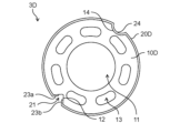
- FIG. 14 is a side view of a vibration isolator 3D according to modification 4.
- the rubber material 10D may have a recess 14 provided at a position facing the recess 12 across the center of the vibration isolator 3D.
- the recess 14 is provided at a position 180° opposite the recess 12.
- the recess 14 is not a side surface of the rubber material 10D, but an outer peripheral surface recess provided on the outer peripheral surface.
- the recess 14 is a recess formed by recessing the outer peripheral surface of the rubber material 10D, similar to the recess 12.
- the side view shape of the outer peripheral surface of the rubber material 10D at the recess 14 is an arc shape.
- the outer peripheral surface of the rubber material 10D at the recess 14 is a cylindrical surface.
- the metal ring 20D has a recess 24 provided at a position facing the dividing portion 21 across the center of the vibration isolator 3D.
- the recess 24 is provided at a position 180° opposite the dividing portion 21.
- the recess 24 is a recessed portion formed by depressing the metal ring 20D.
- the shape of the metal ring 20D at the recess 24 in a side view is an arc shape.
- the outer peripheral surface of the metal ring 20D at the recess 24 is a cylindrical surface.
- the recess 24 of the metal ring 20D is fitted into the recess 14 of the rubber material 10D.
- the vibration isolator 3D configured in this manner provides the following effects in addition to the effects of the vibration isolator 3 in the above embodiment.
- the metal ring 20D can apply a load stress (tightening force) to the rubber material 10D at a specific position.
- the tightening force that the rubber material 10D receives is different at at least two positions in the circumferential direction.
- the metal ring 20D can apply a load stress concentrated at two points separated by ⁇ 90° from the dividing portion 21.
- the recess 24 functions as a structure that causes the tightening force that the rubber material 10D receives to differ at at least two positions in the circumferential direction when the rubber material 10D is tightened by the metal ring 20D.
- the vibration isolator 3D when the vibration isolator 3D is tightened by the tightening member 200, the first end 23a and the second end 23b of the metal ring 20D are aligned without misalignment. Therefore, the vibration isolator 3D can more reliably prevent the rubber material 10D from receiving an excessive tightening force.
- FIG. 15 is a side view of the vibration-isolating device 3E according to the modified example 5. Specifically, as in the vibration-isolating device 3E shown in FIG. 15, the first end 23a and the second end 23b of the metal ring 20E are not bent, and the metal ring 20E may only have a recess 24 at a position 180° opposite the dividing portion 21. In the vibration-isolating device 3E shown in FIG.
- the recess 24 serves as a fulcrum (starting point) to deform the metal ring 20E. Therefore, the variation in the starting point when the metal ring 20E is deformed is suppressed, and the metal ring 20E can impart a load stress (tightening force) to the rubber material 10D at a specific position.
- the vibration isolator 3E is tightened by the tightening member 200, the first end 23a and the second end 23b of the metal ring 20E are aligned without misalignment. Therefore, even with the structure of the vibration isolator 3E shown in FIG. 15, it is possible to prevent excessive tightening force from being applied.
- FIG. 16 is a side view of a vibration isolator 3F according to a sixth modified example.
- the metal ring 20F may have a continuous annular shape around the entire circumference without being divided in the middle.
- the metal ring 20F may have an uneven structure in which convex portions and concave portions are repeatedly provided around the entire circumference in the circumferential direction.
- the metal ring 20F may be configured to have a jagged structure in which convex portions and concave portions having triangular cross sections are repeatedly provided.
- the multiple convex portions and multiple concave portions in the metal ring 20F may be provided at equal intervals along the circumferential direction.
- the number of convex portions and concave portions in the metal ring 20F may be six or more.
- the metal ring 20F is provided with ten convex portions and ten concave portions.
- the height of the convex portions and the depth of the concave portions of the metal ring 20F should be at least twice the thickness of the metal plate that constitutes the metal ring 20F.
- the height of the convex portions and the depth of the concave portions of the metal ring 20F should be no more than 1/3 of the radius of the rubber material 10F.
- the outer peripheral surface of the rubber material 10F is in contact with the metal ring 20F, so it has the same uneven structure as the metal ring 20F.
- the vibration isolator 3F which includes a metal ring 20F with a concave-convex structure, provides the following effects.
- the metal ring 20F of the vibration isolator 3F has an uneven structure, so when the vibration isolator 3F is fastened by the fastening member 200, the fastening force that the rubber material 10F receives from the metal ring 20F is not constant, and the repulsive force of the metal ring 20F due to the fastening force (compression force) can be dispersed and released. Specifically, the repulsive force can be dispersed evenly as many times as there are convex portions or concave portions in the uneven structure of the metal ring 20F.
- the fastening force that the rubber material 10F receives is different at at least two positions in the circumferential direction.
- the fastening force that the rubber material 10F receives is different at the positions of the convex portions and concave portions in the uneven structure of the metal ring 20F, and the load stress can be distributed and applied to the rubber material 10F as many times as there are convex portions or concave portions in the uneven structure.
- the uneven structure of the metal ring 20F functions as a structure that makes the tightening force that the rubber material 10F receives different at at least two positions in the circumferential direction when the rubber material 10F is tightened by the metal ring 20F. This makes it possible for the vibration isolator 3F to prevent excessive tightening force from being received.
- the hardness of the rubber material 10F of the vibration-proof device 3F is low.
- the tightening force of the tightening member 200 is increased to prevent the motor from falling, the rubber material 10F is compressed and deformed, the rubber material 10F becomes dense, and the apparent hardness of the rubber material 10F increases, which may reduce the vibration-proofing effect.
- the part where the rubber material becomes dense (the part where the hardness increases) due to tightening by the tightening member 200 may be concentrated in a part of the 360° circumferential direction.
- the metal ring 20F is a continuous ring without a divided portion and has an uneven structure, so that the repulsive force of the metal ring 20F caused by the tightening force of the tightening member 200 can be dispersed and released.
- the density of the rubber material 10F can be made uniform in the 360° circumferential direction, and the occurrence of dense portions of the rubber material 10F can be suppressed. This allows the vibration isolator 3F to provide a stable vibration damping effect.
- the vibration isolator 3 in the above embodiment has a recessed portion 12 in the rubber material 10.
- the rubber material 10 of the vibration isolator 3 may not have a recessed portion 12 and the outer circumferential surface may be a perfect circle.
- the motor body 2 is a molded motor.
- one of the first bracket 2e and the second bracket 2f may be a cylindrical case with a bottom, and the other of the first bracket 2e and the second bracket 2f may be a lid that covers an opening of the case.
- the motor body 2 is a brushless motor that does not use brushes.
- the motor body 2 may be a commutator motor that uses brushes and a commutator.
- the motor 1 is used as a fan motor for an air conditioner, but this is not limited to this.
- the motor 1 of the present disclosure may be used in devices other than air conditioners, and may be used as a motor other than a fan motor.
- this disclosure also includes forms obtained by applying various modifications conceivable by a person skilled in the art to the above-mentioned embodiments and modifications, or forms realized by arbitrarily combining the components and functions of the embodiments within the scope of the present disclosure.
- This disclosure also includes any combination of two or more claims from among the multiple claims described in the claims at the time of filing this application, within the scope of technical compatibility. For example, when a cited-form claim described in the claims at the time of filing this application is made into a multi-claim or multi-multi-claim so as to cite all of the higher claims within the scope of technical compatibility, the combination of all claims included in that multi-claim or multi-multi-claim is also included in this disclosure.
- the technology disclosed herein can be widely used in a variety of devices equipped with motors.
Landscapes
- Engineering & Computer Science (AREA)
- General Engineering & Computer Science (AREA)
- Chemical & Material Sciences (AREA)
- Combustion & Propulsion (AREA)
- Physics & Mathematics (AREA)
- Acoustics & Sound (AREA)
- Aviation & Aerospace Engineering (AREA)
- Mechanical Engineering (AREA)
- Power Engineering (AREA)
- Vibration Prevention Devices (AREA)
Priority Applications (2)
| Application Number | Priority Date | Filing Date | Title |
|---|---|---|---|
| JP2025537738A JPWO2025028087A1 (https=) | 2023-08-02 | 2024-06-26 | |
| CN202480048589.4A CN121620857A (zh) | 2023-08-02 | 2024-06-26 | 隔振件及具有隔振件的马达 |
Applications Claiming Priority (2)
| Application Number | Priority Date | Filing Date | Title |
|---|---|---|---|
| JP2023125959 | 2023-08-02 | ||
| JP2023-125959 | 2023-08-02 |
Publications (1)
| Publication Number | Publication Date |
|---|---|
| WO2025028087A1 true WO2025028087A1 (ja) | 2025-02-06 |
Family
ID=94394395
Family Applications (1)
| Application Number | Title | Priority Date | Filing Date |
|---|---|---|---|
| PCT/JP2024/023079 Pending WO2025028087A1 (ja) | 2023-08-02 | 2024-06-26 | 防振具及び防振具を有するモータ |
Country Status (3)
| Country | Link |
|---|---|
| JP (1) | JPWO2025028087A1 (https=) |
| CN (1) | CN121620857A (https=) |
| WO (1) | WO2025028087A1 (https=) |
Citations (6)
| Publication number | Priority date | Publication date | Assignee | Title |
|---|---|---|---|---|
| JPS5179213A (ja) * | 1975-01-06 | 1976-07-10 | Hitachi Ltd | Dendoki |
| JPS5128589Y1 (https=) * | 1969-07-02 | 1976-07-19 | ||
| JP2002171717A (ja) * | 2000-12-04 | 2002-06-14 | Ricoh Elemex Corp | モータ |
| JP2013183500A (ja) * | 2012-02-29 | 2013-09-12 | Fujitsu General Ltd | 振動体保持具および同振動体保持具を備えた電動機 |
| CN203416091U (zh) * | 2013-08-15 | 2014-01-29 | 珠海格力电器股份有限公司 | 防震胶圈及电机 |
| JP2018093564A (ja) | 2016-11-30 | 2018-06-14 | パナソニックIpマネジメント株式会社 | モータ |
-
2024
- 2024-06-26 WO PCT/JP2024/023079 patent/WO2025028087A1/ja active Pending
- 2024-06-26 JP JP2025537738A patent/JPWO2025028087A1/ja active Pending
- 2024-06-26 CN CN202480048589.4A patent/CN121620857A/zh active Pending
Patent Citations (6)
| Publication number | Priority date | Publication date | Assignee | Title |
|---|---|---|---|---|
| JPS5128589Y1 (https=) * | 1969-07-02 | 1976-07-19 | ||
| JPS5179213A (ja) * | 1975-01-06 | 1976-07-10 | Hitachi Ltd | Dendoki |
| JP2002171717A (ja) * | 2000-12-04 | 2002-06-14 | Ricoh Elemex Corp | モータ |
| JP2013183500A (ja) * | 2012-02-29 | 2013-09-12 | Fujitsu General Ltd | 振動体保持具および同振動体保持具を備えた電動機 |
| CN203416091U (zh) * | 2013-08-15 | 2014-01-29 | 珠海格力电器股份有限公司 | 防震胶圈及电机 |
| JP2018093564A (ja) | 2016-11-30 | 2018-06-14 | パナソニックIpマネジメント株式会社 | モータ |
Also Published As
| Publication number | Publication date |
|---|---|
| JPWO2025028087A1 (https=) | 2025-02-06 |
| CN121620857A (zh) | 2026-03-06 |
Similar Documents
| Publication | Publication Date | Title |
|---|---|---|
| KR100300841B1 (ko) | 모터수용용케이싱유니트 | |
| US8492940B2 (en) | Apparatus for holding an electrical machine such that it is decoupled from vibration | |
| CN103155359A (zh) | 用于在电机的壳体中紧固定子的张紧轮 | |
| JP2019011837A (ja) | 防振部材、ファンモータ、及び、取付構造 | |
| US4452541A (en) | Motor armature shaft endplay reduction apparatus | |
| WO2025028087A1 (ja) | 防振具及び防振具を有するモータ | |
| US6927526B2 (en) | Motor | |
| US6087749A (en) | Rotary polygonal mirror driving apparatus | |
| JP6523372B2 (ja) | ステータと一体化されたハウジングを備えた電動機 | |
| US6563239B1 (en) | Fitting arrangement for an antivibration mounting for an electromotor | |
| US6276832B1 (en) | Collapsible bearing retainer | |
| JP2018204573A (ja) | 緩衝部材および緩衝部材を備えた送風装置 | |
| CN215175858U (zh) | 减振组件以及空调 | |
| JP2015124712A (ja) | 送風機 | |
| US20070144852A1 (en) | Dynamic damper and hollow propeller shaft equipped with same | |
| JP3238048U (ja) | 防振グロメットおよびファンモータ | |
| JP4393904B2 (ja) | モータの取付構造、及び送風装置 | |
| KR20110023626A (ko) | 축 방향 체결 하중을 부여하는 스냅링 | |
| US20210203201A1 (en) | Cylindrical mounting sleeve with an elongated protrusion on an inner surface | |
| JP2022147644A (ja) | 車載用電動流体機械 | |
| JP2005024092A (ja) | コンプライアントスペーサおよびそのスペーサを用いた組立体 | |
| JP7499206B2 (ja) | モータの固定構造 | |
| JP2002054825A (ja) | 空気調和機の室外機 | |
| US12560236B2 (en) | Bearing spacer | |
| JP3507245B2 (ja) | モータ |
Legal Events
| Date | Code | Title | Description |
|---|---|---|---|
| 121 | Ep: the epo has been informed by wipo that ep was designated in this application |
Ref document number: 24848747 Country of ref document: EP Kind code of ref document: A1 |
|
| ENP | Entry into the national phase |
Ref document number: 2025537738 Country of ref document: JP Kind code of ref document: A |
|
| WWE | Wipo information: entry into national phase |
Ref document number: 2024848747 Country of ref document: EP |
|
| NENP | Non-entry into the national phase |
Ref country code: DE |