WO2025028080A1 - 上向流式イオン交換塔の運転方法 - Google Patents
上向流式イオン交換塔の運転方法 Download PDFInfo
- Publication number
- WO2025028080A1 WO2025028080A1 PCT/JP2024/022959 JP2024022959W WO2025028080A1 WO 2025028080 A1 WO2025028080 A1 WO 2025028080A1 JP 2024022959 W JP2024022959 W JP 2024022959W WO 2025028080 A1 WO2025028080 A1 WO 2025028080A1
- Authority
- WO
- WIPO (PCT)
- Prior art keywords
- water
- ion exchange
- exchange tower
- tower
- fixed bed
- Prior art date
- Legal status (The legal status is an assumption and is not a legal conclusion. Google has not performed a legal analysis and makes no representation as to the accuracy of the status listed.)
- Pending
Links
Images



Classifications
-
- B—PERFORMING OPERATIONS; TRANSPORTING
- B01—PHYSICAL OR CHEMICAL PROCESSES OR APPARATUS IN GENERAL
- B01J—CHEMICAL OR PHYSICAL PROCESSES, e.g. CATALYSIS OR COLLOID CHEMISTRY; THEIR RELEVANT APPARATUS
- B01J39/00—Cation exchange; Use of material as cation exchangers; Treatment of material for improving the cation exchange properties
- B01J39/04—Processes using organic exchangers
- B01J39/05—Processes using organic exchangers in the strongly acidic form
-
- B—PERFORMING OPERATIONS; TRANSPORTING
- B01—PHYSICAL OR CHEMICAL PROCESSES OR APPARATUS IN GENERAL
- B01J—CHEMICAL OR PHYSICAL PROCESSES, e.g. CATALYSIS OR COLLOID CHEMISTRY; THEIR RELEVANT APPARATUS
- B01J41/00—Anion exchange; Use of material as anion exchangers; Treatment of material for improving the anion exchange properties
- B01J41/04—Processes using organic exchangers
- B01J41/05—Processes using organic exchangers in the strongly basic form
-
- B—PERFORMING OPERATIONS; TRANSPORTING
- B01—PHYSICAL OR CHEMICAL PROCESSES OR APPARATUS IN GENERAL
- B01J—CHEMICAL OR PHYSICAL PROCESSES, e.g. CATALYSIS OR COLLOID CHEMISTRY; THEIR RELEVANT APPARATUS
- B01J47/00—Ion-exchange processes in general; Apparatus therefor
- B01J47/02—Column or bed processes
- B01J47/026—Column or bed processes using columns or beds of different ion exchange materials in series
-
- B—PERFORMING OPERATIONS; TRANSPORTING
- B01—PHYSICAL OR CHEMICAL PROCESSES OR APPARATUS IN GENERAL
- B01J—CHEMICAL OR PHYSICAL PROCESSES, e.g. CATALYSIS OR COLLOID CHEMISTRY; THEIR RELEVANT APPARATUS
- B01J47/00—Ion-exchange processes in general; Apparatus therefor
- B01J47/14—Controlling or regulating
-
- B—PERFORMING OPERATIONS; TRANSPORTING
- B01—PHYSICAL OR CHEMICAL PROCESSES OR APPARATUS IN GENERAL
- B01J—CHEMICAL OR PHYSICAL PROCESSES, e.g. CATALYSIS OR COLLOID CHEMISTRY; THEIR RELEVANT APPARATUS
- B01J49/00—Regeneration or reactivation of ion-exchangers; Apparatus therefor
- B01J49/05—Regeneration or reactivation of ion-exchangers; Apparatus therefor of fixed beds
- B01J49/08—Regeneration or reactivation of ion-exchangers; Apparatus therefor of fixed beds containing cationic and anionic exchangers in separate beds
-
- B—PERFORMING OPERATIONS; TRANSPORTING
- B01—PHYSICAL OR CHEMICAL PROCESSES OR APPARATUS IN GENERAL
- B01J—CHEMICAL OR PHYSICAL PROCESSES, e.g. CATALYSIS OR COLLOID CHEMISTRY; THEIR RELEVANT APPARATUS
- B01J49/00—Regeneration or reactivation of ion-exchangers; Apparatus therefor
- B01J49/50—Regeneration or reactivation of ion-exchangers; Apparatus therefor characterised by the regeneration reagents
- B01J49/53—Regeneration or reactivation of ion-exchangers; Apparatus therefor characterised by the regeneration reagents for cationic exchangers
-
- B—PERFORMING OPERATIONS; TRANSPORTING
- B01—PHYSICAL OR CHEMICAL PROCESSES OR APPARATUS IN GENERAL
- B01J—CHEMICAL OR PHYSICAL PROCESSES, e.g. CATALYSIS OR COLLOID CHEMISTRY; THEIR RELEVANT APPARATUS
- B01J49/00—Regeneration or reactivation of ion-exchangers; Apparatus therefor
- B01J49/50—Regeneration or reactivation of ion-exchangers; Apparatus therefor characterised by the regeneration reagents
- B01J49/57—Regeneration or reactivation of ion-exchangers; Apparatus therefor characterised by the regeneration reagents for anionic exchangers
-
- B—PERFORMING OPERATIONS; TRANSPORTING
- B01—PHYSICAL OR CHEMICAL PROCESSES OR APPARATUS IN GENERAL
- B01J—CHEMICAL OR PHYSICAL PROCESSES, e.g. CATALYSIS OR COLLOID CHEMISTRY; THEIR RELEVANT APPARATUS
- B01J49/00—Regeneration or reactivation of ion-exchangers; Apparatus therefor
- B01J49/70—Regeneration or reactivation of ion-exchangers; Apparatus therefor for large scale industrial processes or applications
Definitions
- the present invention relates to a method for operating an upflow ion exchange tower, and in particular to a method for operating an upflow ion exchange tower in which the upflow water velocity (LV) is changed according to the demand for deionized water.
- LV upflow water velocity
- One method of operating an ion exchange tower, which contains ion exchange resin in a container and passes raw water through it to obtain deionized water, is the upward flow method, in which raw water is passed through the tower in an upward direction.
- Patent Document 1 When raw water is passed through an ion exchange tower in an upward flow, there is a risk that the ions will not be adsorbed and will leak out if the ion exchange resin flows. For this reason, a fixed bed is often formed in an upward flow ion exchange tower (Patent Document 1).
- a cylindrical container is installed with the axis of the cylinder in the up-down direction (particularly the vertical direction).
- Permeable partition plates are provided at the top and bottom of this container, and ion exchange resin is contained between the permeable partition plates.
- the ion exchange resin itself swells and shrinks as water is withdrawn and regenerated, increasing or decreasing its volume. Therefore, in order to allow the regenerated chemicals to pass evenly through the resin layer, the resin is contained in the container with a space of a certain height (freeboard section) remaining.
- the ion exchange resin located at the bottom of the ion exchange resin packing layer has broken through, but the ion exchange resin located at the top has not yet broken through, when water sampling is stopped midway through operation (when raw water flow is stopped), the resin that has broken through at the bottom and the resin that has not yet broken through at the top will mix together, which may cause the quality of the treated water to deteriorate the next time water sampling operation is resumed.
- water is passed through at a speed above a certain level (high LV) at the start of water collection to form a fixed bed of ion exchange resin. After the fixed bed is formed, raw water is passed through at a constant flow rate to produce deionized water such as pure water.
- high LV certain level
- the objective of the present invention is to provide a method for operating an upflow ion exchange tower that can change the amount of deionized water produced in response to fluctuations in the amount of deionized water required at the point of deionized water demand.
- the method of operating an upflow ion exchange tower of the present invention is a method of operating an upflow ion exchange tower having a packed bed of ion exchange resin between a lower water-permeable partition plate and an upper water-permeable partition plate, in which raw water is passed upward by a feed pump to produce deionized water.
- the method includes a fixed bed formation step in which, at the start of water passage, raw water is passed through the ion exchange tower at a high LV to push up the packed bed of ion exchange resin in the ion exchange tower and press it against the upper water-permeable partition plate to form a fixed bed of ion exchange resin, and a steady operation step in which raw water is then passed through the ion exchange tower at an LV greater than the minimum LV at which the fixed bed is maintained, and the amount of raw water passed through is controlled according to the demand for deionized water.
- the method for operating an upflow ion exchange tower introduces deionized water from the ion exchange tower into a deionized water tank via a flow control valve, and delivers the deionized water from the deionized water tank to a demand destination of the deionized water, controlling the opening of the flow control valve and/or the water supply pump so that the water level in the deionized water tank is within a predetermined range and the fixed bed of the ion exchange tower is maintained.
- the method of operating an upflow ion exchange tower of the present invention makes it possible to change the amount of deionized water produced in response to fluctuations in the amount of pure water required at the point of demand.
- the method of operating an upflow ion exchange tower of the present invention controls the amount of water passing through the ion exchange tower according to the required amount of deionized water, reducing the unit power consumption of the water supply pump and reducing the frequency of regeneration and replacement of the ion exchange resin.
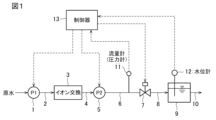
- FIG. 1 is a configuration diagram of a pure water production system to which a method of operating an upflow ion exchange column according to an embodiment of the present invention is applied.
- 1 is a configuration diagram of a pure water production system to which a method of operating an upflow ion exchange column according to an embodiment of the present invention is applied.
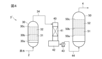
- FIG. 2 is a configuration diagram of an ion exchange device.
- FIG. 2 is a diagram showing the configuration of an ion exchange device.
- Figure 1 shows an example of a pure water production system to which the operating method of the upflow ion exchange tower of the present invention is applied.
- Raw water to be deionized is supplied to ion exchange device 3 by first pump 1 and piping 2, passed through the ion exchange tower installed in ion exchange device 3, and deionized by contact with ion exchange resin to become pure water (deionized water).
- Raw water flows upward through the ion exchange tower of ion exchange device 3.
- the pure water from the ion exchange device 3 is introduced into the pure water tank 9 via pipe 4, second pump 5, pipe 6, flow control valve 7, and pipe 8, and is then sent to the pure water demand point via pipe 10.
- a flow meter or pressure gauge 11 is installed in pipe 6, and a water level gauge 12 is installed in the pure water tank 9, and the detection signals from each are input to a controller 13.
- the controller 13 adjusts the opening of the flow control valve 7 using PID control or the like so that the water level detected by the water level gauge 12 falls within a specified range.
- the amount of water sent from the pure water tank 9 to the pure water demand point varies depending on the amount of pure water used at the pure water demand point, and the water level in the pure water tank 9 changes accordingly; however, by controlling the opening of the flow rate adjustment valve 7, the amount of raw water being treated is controlled so that the water level in the pure water tank 9 remains within a specified range.
- the amount of water flowing to the ion exchange device 3 is controlled depending on the amount of water sent from the pure water tank 9 to the pure water demand point via the piping 10.
- the controller 13 also inverter controls the water flow rate (motor rotation speed) of the first pump 1 or the second pump 5 so that the flow rate or pressure detected by the flowmeter or pressure gauge 11 after the opening of the flow control valve 7 is adjusted falls within a predetermined range.
- the predetermined range of the flow rate or pressure is set so that a fixed bed is maintained in the ion exchange tower of the ion exchange device 3.
- the amount of water passing through the ion exchange tower is controlled in accordance with the amount of pure water used at the point of demand and so that the fixed bed of the ion exchange tower is maintained.
- FIG. 2 shows another example of a pure water production system to which the method of operating an upflow ion exchange tower of the present invention is applied.
- a flowmeter or pressure gauge 11 is installed in the pipe 8
- a pressure gauge 14 is installed in the pipe 6, and the detection signals of each and the detection signal of the water level gauge 12 in the pure water tank 9 are input to the controller 13.
- the opening of the flow control valve 7 is controlled so that the water level detected by the water level gauge 12 is within a predetermined range.
- the rotation speed of one or both of the first pump 1 and the second pump 5 is inverter controlled so that the detected pressure of the pressure gauge 14 after the opening of the flow control valve 7 is adjusted and either the detected flow rate or pressure of the flow meter or pressure gauge 11 or both are within a predetermined range (a range that maintains the fixed bed of the ion exchange tower).
- the pure water production system of FIG. 2 also controls the amount of water flowing to the ion exchange device 3 according to the amount of water sent from the pure water tank 9 through the piping 10 to the pure water demand point, and so as to maintain the fixed bed of the ion exchange tower. This reduces the pump power consumption during operation of the pure water production system, and also reduces the frequency of regeneration and replacement of the ion exchange resin.
- the frequency of flow rate adjustment operations of the first pump 1 or the second pump 5 is 7 times/min or less, and the range of flow rate fluctuation per operation is half the maximum flow rate or less.
- the pure water production apparatus of FIG. 1 or FIG. 2 is suitable for incorporation into the primary pure water system of an ultrapure water production apparatus, but may also be used for other purposes.
- the configuration of the ion exchange device 3 is not particularly limited.
- An example of a configuration that can be adopted as the ion exchange device 3 is shown in Figures 3 and 4.
- a cylindrical cation exchange tower 21 and an anion exchange tower 23 are disposed within a housing 26.
- the cation exchange tower 21 and anion exchange tower 23 are installed so that the axis of the cylinders is vertical.
- Raw water from pipe 2 is introduced into the cation exchange tower 21, where it flows upward and is subjected to cation exchange treatment. It is then introduced into the anion exchange tower 23 via pipe 25, where it flows upward and is subjected to anion exchange treatment to become pure water, which then flows out into pipe 4.
- the cation exchange tower 21 is provided with a packed bed 22 of strong acid cation exchange resin.
- Water-permeable partition plates 21a, 21b having water passage parts are horizontally provided on the lower and upper sides of the packed bed 22.
- the water passage parts of the partition plates 21a, 21b are configured to allow water to pass through but not allow cation exchange resin particles to pass through.
- the packed bed 22 is pushed up and pressed against the upper partition plate 21b to form a fixed bed.
- the distance between the upper surface of the packed bed 22 and the water-permeable partition plate 21b when no water is passing through is preferably 40% or more, particularly 50 to 70%, of the height of the packed bed 22 when no water is passing through (the packed bed height). The same applies to the anion exchange tower described later.
- the cation exchange resin is regenerated by passing hydrochloric acid downflow.
- the anion exchange resin is regenerated by passing an aqueous sodium hydroxide solution downward.
- raw water from pipe 2 is introduced into the cation exchange tower 30, where it is passed upward and subjected to cation exchange treatment, and then sent to the decarbonation tower 40 via pipe 34 and subjected to decarbonation treatment.
- the decarbonated water is introduced into the anion exchange tower 50 via pump 43 and pipe 44, where it is passed upward and subjected to anion exchange treatment to become deionized water, which then flows out into pipe 4.
- the cation exchange tower 30 is provided with packed beds 31, 32 of strong acid cation exchange resin.
- Permeable partition plates 30a, 30b, 30c with water passage sections are horizontally provided below the lower packed bed 31 and below and above the upper packed bed 32.
- the water passage sections of the permeable partition plates 30a to 30c are configured to allow water to pass through but not allow cation exchange resin particles to pass through.
- the packed beds 31, 32 are pushed up and pressed against the upper permeable partition plates 30b or 30c, respectively, to form fixed beds.
- the cation exchange resin is regenerated by passing hydrochloric acid downflow.
- the decarbonation tower 40 has a filler layer 41.
- the pressure inside the decarbonation tower 40 is reduced by a vacuum pump (not shown).
- a vacuum pump not shown
- the dissolved carbon dioxide gas in the water is degassed.
- the water that falls into the pit 42 is pumped by a pump 43.
- the anion exchange tower 50 has packed beds 51, 52 of strong basic anion exchange resin. Permeable partition plates 50a, 50b, 50c with water passage sections are horizontally installed on the lower side of the lower packed bed 51 and on the lower and upper sides of the upper packed bed 52. In a steady water flow state, the packed beds 51, 52 are pushed up and pressed against the upper permeable partition plates 50b or 50c, respectively, to form fixed beds.
- the anion exchange resin is regenerated by passing an aqueous sodium hydroxide solution downward.
- a fixed bed in the fixed bed formation process at the start of water flow into an ion exchange tower containing ion exchange resin with an average particle size of about 500 to 700 ⁇ m, it is preferable to form a fixed bed by flowing water upward at an LV of 20 m/h or more, for example, 20 to 70 m/h, and particularly about 20 to 50 m/h.
- the water is circulated upward at a smaller LV (but not less than the minimum LV that can maintain a fixed bed), and the amount of water flowing is controlled in response to changes in the demand for deionized water.
- This minimum LV should be sufficient to maintain the floating of the ion exchange resin, and can be set appropriately, for example, between 6 m/h and 20 m/h.
- Example 1 As shown in Fig. 3, a water flow test was carried out using an ion exchange apparatus 3 having a cation exchange tower 21 and an anion exchange tower 23 in one tower. The main conditions were as follows.
- ⁇ Fixed bed formation step> Water was passed through the column at LV 20 m/h for 10 minutes to form a fixed bed.
- Tables 1 and 2 also show the value MPa/m (differential pressure per 1 m of packed bed) obtained by dividing the measured differential pressure (MPa) by the height of the packed bed (m).
- Tables 3 and 4 also show the value MPa/m (differential pressure per 1 m of packed bed) obtained by dividing the measured differential pressure (MPa) by the height of the packed bed (m).
- Example 4-1 Two columns with an inner diameter of 40 mm and a height of 1000 mm were prepared, and one column was filled with 500 mL of H-type cation resin (packed bed height ⁇ 400 mm). The other column was filled with 1000 mL of OH-type anion resin (packed bed height ⁇ 800 mm). These columns were connected by piping so that the liquid was passed through the cation-filled column ⁇ anion-filled column in the order of upward flow.
- the H-type cation exchange resin was a regenerated Na-type cation exchange resin, and the average particle size was 650 ⁇ m.
- the OH-type anion exchange resin was a regenerated Cl-type anion exchange resin, and the average particle size was 550 ⁇ m.
- Permeable partitions were placed below the packed bed of cation exchange resin and at the top of the column, and below the packed bed of anion exchange resin and at the top of the column.
- Reference Signs List 3 3' Ion exchange device 7 Flow rate control valve 9 Pure water tank 11 Flow meter or pressure gauge 12 Water level gauge 13 Controller 14 Pressure gauge 21 Cation exchange tower 21a, 21b Water-permeable partition plate 22 Cation exchange resin 23 Anion exchange tower 23a, 23b Water-permeable partition plate 24 Anion exchange resin 30 Cation exchange tower 30a, 30b, 30c Water-permeable partition plate 31, 32 Cation exchange resin 40 Decarbonation tower 50 Anion exchange tower 50a, 50b, 50c Water-permeable partition plate 51, 52 Anion exchange resin
Landscapes
- Chemical & Material Sciences (AREA)
- Organic Chemistry (AREA)
- Chemical Kinetics & Catalysis (AREA)
- Treatment Of Water By Ion Exchange (AREA)
- Life Sciences & Earth Sciences (AREA)
- Hydrology & Water Resources (AREA)
- Engineering & Computer Science (AREA)
- Environmental & Geological Engineering (AREA)
- Water Supply & Treatment (AREA)
Abstract
下側の透水性仕切板と上側の透水性仕切板との間にイオン交換樹脂の充填床を有するイオン交換塔に、給水ポンプによって原水を上向流にて通水して脱イオン水を製造する上向流式イオン交換塔の運転方法であって、通水開始当初に、イオン交換塔内に高LVにて原水を通水して、該イオン交換塔内のイオン交換樹脂の充填床を押し上げ、該充填床の上側の透水性仕切板に押し当ててイオン交換樹脂の固定床を形成する固定床形成工程と、その後、該固定床が維持される最小LVよりも大きいLVにて原水を通水し、かつ脱イオン水の需要量に応じて原水の通水量を制御する定常運転工程とを有する上向流式イオン交換塔の運転方法。
Description
本発明は上向流式イオン交換塔の運転方法に係り、特に脱イオン水の需要量に応じて上向流通水速度(LV)を変化させる上向流式イオン交換塔の運転方法に関する。
容器内にイオン交換樹脂を収容したイオン交換塔に原水を通水して脱イオン水を得るイオン交換塔の運転方法として、原水を上向流にて通水する上向流通水方式がある。
原水をイオン交換塔に上向流にて通水する場合、イオン交換樹脂が流動すると、イオンが吸着されきれずにリークするおそれがある。そのため、上向流式イオン交換塔では固定床を形成することが多い(特許文献1)。
一般的な上向流式のイオン交換塔にあっては、円筒状の容器が筒軸心方向を上下方向(特に鉛直方向)として設置されている。この容器内の上部と下部にそれぞれ透水性仕切板が設けられており、該透水性仕切板間にイオン交換樹脂が収容されている。イオン交換樹脂は採水・再生によって樹脂自体が膨潤・収縮し、その体積が増減する。そこで再生薬品を樹脂層に均一に通水するために、所定高さの空間(フリーボード部)を残した状態で容器に収容されている。
このようなイオン交換樹脂塔に原水を上向流にて通水すると、イオン交換樹脂はこの上向流によって押し上げられ、上側の透水性仕切板に押し付けられた固定床状態となり、この状態で採水が行われる。処理水は、容器頂部の流出口から流出する。
イオン交換塔への原水の通水を停止すると、イオン交換樹脂を押し上げる力が消失するので、固定床を形成していたイオン交換樹脂は、容器内において下側の透水性仕切板側へ沈降落下し、通水前の収容状態に復帰する。
このようにイオン交換樹脂が容器内で沈降落下する場合、イオン交換樹脂の崩落部が形成される。この崩落部が徐々に上方に移動し、遂には最上部のイオン交換樹脂にまで達してイオン交換樹脂の落下が終了する。このイオン交換樹脂の崩落部においては、イオン交換樹脂粒子が混ざり合いながら落下する。そのため、イオン交換樹脂の充填層の下位側に位置していたイオン交換樹脂は破過(ブレーク)しているが、上位側に位置していたイオン交換樹脂はまだ破過していない運転中途状態で採水を停止した場合(原水通水を停止した場合)には、下位側の破過した樹脂と上位側の未破過樹脂とが混ざり合ってしまい、次回の採水運転再開時に処理水質が悪化することがある。
そのため、上向流通水方式で運転するイオン交換塔にあっては、一度上向流通水により採水を開始すると、採水完了(次の再生)まで連続通水し続けるのが一般的である。
上記の通り、従来の上向流式のイオン交換塔では、採水開始時にある所定以上の速度(高LV)で通水し、イオン交換樹脂の固定床を形成する。固定床形成後は一定の流速で原水が通水され、純水などの脱イオン水が製造されている。
しかしながら、純水需要箇所の使用水量は、純水需要箇所の稼働状況に応じて常に変化している。そのため、イオン交換塔を備えた従来の純水製造装置では、純水需要箇所が必要とする水量の最大量の純水を製造しており、余剰な純水が製造されている。この余剰に製造された純水は、純水製造装置の給水として再利用されている。
再生型のイオン交換塔を有する純水製造装置においては、所定量の純水を採水した後、イオン交換塔のイオン交換樹脂の再生が行われる。上記のように余剰の純水を給水として再利用する場合、給水のイオン負荷量が小さくなるため、採水できる体積が増加する。しかし余剰となる純水量の予想はできず、どれだけの余剰純水が給水として再利用されるかわからないので、原水のイオン負荷量での設計で定体積の採水量を設定している。そのため、実際のイオン負荷量が小さい場合であっても、採水量が上記定体積に到達した場合には、再生が行われる。この結果、再生頻度が多くなり、余分な再生薬品が使用されている。
本発明は、脱イオン水需要箇所の脱イオン水の必要量の変動に対応して脱イオン水の生産量を変化させることができる上向流式イオン交換塔の運転方法を提供することを課題とする。
本発明の上向流式イオン交換塔の運転方法は、下側の透水性仕切板と上側の透水性仕切板との間にイオン交換樹脂の充填床を有するイオン交換塔に、給水ポンプによって原水を上向流にて通水して脱イオン水を製造する上向流式イオン交換塔の運転方法であって、通水開始当初に、イオン交換塔内に高LVにて原水を通水して、該イオン交換塔内のイオン交換樹脂の充填床を押し上げ、該充填床の上側の透水性仕切板に押し当ててイオン交換樹脂の固定床を形成する固定床形成工程と、その後、該固定床が維持される最小LVよりも大きいLVにて原水を通水し、かつ脱イオン水の需要量に応じて原水の通水量を制御する定常運転工程とを有する。
本発明の一態様では、前記定常運転工程においては、前記イオン交換塔からの脱イオン水を流量調整バルブを介して脱イオン水タンクに導入し、該脱イオン水タンクから脱イオン水を脱イオン水の需要先に送水する上向流式イオン交換塔の運転方法であって、該脱イオン水タンク内の水位が所定範囲となるように、かつ前記イオン交換塔の固定床が維持されるように、該流量調整バルブの開度及び/又は前記給水ポンプを制御する。
本発明の一態様では、前記給水ポンプの制御頻度が7回/min以下である。
本発明の上向流式イオン交換塔の運転方法によると、純水需要箇所の純水の必要量の変動に対応して脱イオン水の生産量を変化させることができる。
本発明の上向流式イオン交換塔の運転方法によると、イオン交換塔への通水量を脱イオン水の必要量に応じて制御するため、給水用のポンプ電力原単位が低減されると共に、イオン交換樹脂の再生頻度や交換頻度を減少させることができる。
以下、図面を参照して実施の形態について説明する。
図1は、本発明の上向流式イオン交換塔の運転方法が適用される純水製造装置の一例を示すものである。脱イオン処理される原水は、第1ポンプ1、配管2によりイオン交換装置3に供給され、イオン交換装置3に設けられたイオン交換塔に通水され、イオン交換樹脂と接触して脱イオン処理され、純水(脱イオン水)となる。イオン交換装置3のイオン交換塔には、原水が上向流通水される。
イオン交換塔への通水開始に際しては、イオン交換塔に高LVにて通水し、固定床を形成する。
イオン交換装置3からの純水は、配管4、第2ポンプ5、配管6、流量調整バルブ7及び配管8を経て純水タンク9に導入され、配管10を介して純水需要箇所へ送水される。配管6に流量計又は圧力計11が設置され、純水タンク9に水位計12が設置されており、各々の検出信号が制御器13に入力される。
制御器13は、水位計12で検出される水位が所定範囲となるように、流量調整バルブ7の開度をPID制御等により調整する。
純水需要箇所の純水使用量に応じて、純水タンク9から純水需要箇所への送水量が変動し、これに伴って純水タンク9内の水位が変化するが、流量調整バルブ7の開度を制御することにより、純水タンク9内の水位が所定範囲となるように、原水の処理量が制御される。即ち、純水タンク9から配管10によって純水需要箇所に送水される水量に応じて、イオン交換装置3への通水量が制御される。
また、制御器13は、流量調整バルブ7の開度が調整された後の流量計又は圧力計11の検出流量又は圧力が所定範囲となるように、第1ポンプ1又は第2ポンプ5の送水量(モータ回転数)をインバータ制御する。なお、この流量又は圧力の所定範囲は、イオン交換装置3のイオン交換塔内で固定床が維持される流量となるように設定される。
本発明では、このように純水需要箇所での純水の使用量に応じて、かつイオン交換塔の固定床が維持されるようにイオン交換塔への通水量が制御される。
これにより、イオン交換システムの運転時のポンプ電力原単位が低減されると共に、イオン交換樹脂の再生頻度や交換頻度を減少させることができる。
図2は、本発明の上向流式イオン交換塔の運転方法が適用される純水製造装置の別の一例を示すものである。
図2の純水製造装置では、配管8に流量計又は圧力計11が設置され、配管6に圧力計14が設置されており、各々の検出信号と、純水タンク9の水位計12の検出信号とが制御器13に入力されている。
図2のその他の構成は図1と同一であり、同一符号は同一部分を示している。この純水製造装置においても、イオン交換装置3への通水開始に際しては、イオン交換塔に高LVにてイオン交換塔に通水し、固定床を形成する。
この図2の純水製造装置では、水位計12の検出水位が所定範囲となるように流量調整バルブ7の開度が制御される。また、流量調整バルブ7の開度が調整された後の圧力計14の検出圧力と、流量計又は圧力計11の検出流量又は圧力とのいずれか又は双方が所定範囲(イオン交換塔の固定床を維持する範囲)となるように、第1ポンプ1及び第2ポンプ5の一方又は双方の回転数がインバータ制御される。
この図2の純水製造装置によっても、純水タンク9から配管10によって純水需要箇所に送水される水量に応じて、かつイオン交換塔の固定床が維持されるようにイオン交換装置3への通水量が制御される。これにより、純水製造装置の運転時のポンプ電力原単位が低減されると共に、イオン交換樹脂の再生頻度や交換頻度を減少させることができる。
本発明では、第1ポンプ1又は第2ポンプ5の流量調整操作の頻度は、7回/min以下とされ、1回当りの流量変動幅は最大流量の半分以下とされることが好ましい。
流量調整頻度を7回/min以下とすることが好ましい理由は、以下の通りである。
一般に、ポンプに使用される金属は2×10⁷回擦れると摩耗し疲労破壊する。ポンプを5年間使用すると仮定すると、2×10⁷回/5year/365day/24h/60min=7.62回/minとなる。よって、流量調整回数は7回/min以下とすることが好ましい。
図1又は図2の純水製造装置は、超純水製造装置の一次純水システムに組み込むのに好適であるが他の用途に用いられてもよい。
本発明において、イオン交換装置3の構成は特に限定されるものではない。イオン交換装置3として採用可能な構成の一例を図3,4に示す。
図3のイオン交換装置3では、ハウジング26内にそれぞれ円筒形のカチオン交換塔21とアニオン交換塔23とが配置されている。カチオン交換塔21及びアニオン交換塔23は、円筒の軸心線方向が鉛直方向となるように設置されている。配管2からの原水がカチオン交換塔21に導入され、上向流通水されてカチオン交換処理された後、配管25によってアニオン交換塔23に導入され、上向流通水され、アニオン交換処理されて純水となり、配管4へ流出する。
カチオン交換塔21には強酸性カチオン交換樹脂の充填床22が設けられている。充填床22の下側及び上側にそれぞれ通水部を有した透水性仕切板21a,21bが水平に設けられている。この仕切板21a,21bの通水部は、水は通すが、カチオン交換樹脂粒子は通さないように構成されている。定常の通水状態では、充填床22は、押し上げられ、上側の仕切板21bに押しつけられて固定床となっている。
非通水時における充填床22の上面と透水性仕切板21bとの距離は、非通水時における充填床22の高さ(充填層高)の40%以上、特に50~70%程度が好ましい。後述のアニオン交換塔においても同様である。
非通水時における充填床22の上面と透水性仕切板21bとの距離は、非通水時における充填床22の高さ(充填層高)の40%以上、特に50~70%程度が好ましい。後述のアニオン交換塔においても同様である。
カチオン交換樹脂の再生は、塩酸を下向流で通水することにより行われる。
アニオン交換塔23は、強塩基性アニオン交換樹脂の充填床24を有する。充填床24の下側及び上側にそれぞれ通水部を有した透水性仕切板23a,23bが水平に設けられている。定常の通水状態では、充填床24は、押し上げられ、上側の透水性仕切板23bに押しつけられて固定床となっている。
アニオン交換樹脂の再生は、水酸化ナトリウム水溶液を下向流通水することにより行われる。
図4のイオン交換装置3’では、配管2からの原水がカチオン交換塔30に導入され、上向流通水されてカチオン交換処理された後、配管34によって脱炭酸塔40に送水され、脱炭酸処理される。脱炭酸処理水は、ポンプ43及び配管44によってアニオン交換塔50に導入され、上向流通水され、アニオン交換処理されて脱イオン水となり、配管4へ流出する。
なお、カチオン交換塔30には強酸性カチオン交換樹脂の充填床31,32が設けられている。下側の充填床31の下側と、上側の充填床32の下側及び上側に、それぞれ、通水部を有した透水性仕切板30a,30b,30cが水平に設けられている。この透水性仕切板30a~30cの通水部は、水は通すが、カチオン交換樹脂粒子は通さないように構成されている。定常の通水状態では、充填床31,32は、押し上げられ、各々の上側の透水性仕切板30b又は30cに押しつけられて固定床となっている。
カチオン交換樹脂の再生は、塩酸を下向流で通水することにより行われる。
脱炭酸塔40は、充填材層41を有している。脱炭酸塔40内は真空ポンプ(図示略)により減圧されている。充填材層41を伝わり流れる間に水中の溶存炭酸ガスが脱ガス処理される。ピット42に落下した水がポンプ43によって送水される。
アニオン交換塔50は、強塩基性アニオン交換樹脂の充填床51,52を有する。下側の充填床51の下側と、上側の充填床52の下側及び上側にそれぞれ通水部を有した透水性仕切板50a,50b,50cが水平に設けられている。定常の通水状態では、充填床51,52は、押し上げられ、各々の上側の透水性仕切板50b又は50cに押しつけられて固定床となっている。
アニオン交換樹脂の再生は、水酸化ナトリウム水溶液を下向流通水することにより行われる。
本発明では、平均粒径500~700μm程度のイオン交換樹脂を収容したイオン交換塔への通水開始に際しての固定床形成工程では、20m/h以上、例えば20~70m/h、特に20~50m/h程度のLVで上向流通水して固定床を形成することが好ましい。
その後の定常運転工程では、それよりも小さいLV(ただし、固定床を維持できる最小LV以上)で上向流通水し、脱イオン水の需要量の変化に対応して通水量を制御する。この最小LVは、イオン交換樹脂の浮上を維持できればよく、例えば6m/h以上20m/h以下程度で適宜設定すればよい。
[実験例1]
図3のように、カチオン交換塔21及びアニオン交換塔23を1つの塔内に有するイオン交換装置3を用いて通水試験を行った。主な条件は次の通りである。
図3のように、カチオン交換塔21及びアニオン交換塔23を1つの塔内に有するイオン交換装置3を用いて通水試験を行った。主な条件は次の通りである。
<カチオン交換塔21の構成>
内径:700mm
カチオン交換塔21の仕切板21a,21b間の高さ:700mm
カチオン交換樹脂の固定床の高さ:572mm
カチオン交換樹脂の平均粒径:650μm
<アニオン交換塔23の構成>
内径:700mm
アニオン交換塔23の仕切板23a,23b間の高さ:1200mm
アニオン交換樹脂の固定床の高さ:1105mm
アニオン交換樹脂の平均粒径:550μm
内径:700mm
カチオン交換塔21の仕切板21a,21b間の高さ:700mm
カチオン交換樹脂の固定床の高さ:572mm
カチオン交換樹脂の平均粒径:650μm
<アニオン交換塔23の構成>
内径:700mm
アニオン交換塔23の仕切板23a,23b間の高さ:1200mm
アニオン交換樹脂の固定床の高さ:1105mm
アニオン交換樹脂の平均粒径:550μm
<被処理水>
濃度8mg/Lの食塩水溶液(27℃)
濃度8mg/Lの食塩水溶液(27℃)
<固定床形成工程>
LV=20m/hにて10min通水して固定床を形成した。
LV=20m/hにて10min通水して固定床を形成した。
<定常運転工程>
固定床を形成した後、定常運転工程を行った。この定常運転工程では、通水速度をLV=42.9m/hとLV=90.9m/hとの間で20分周期で変化させた。なお、LV=42.9m/hからLV=90.9m/hまで10minで直線的に通水量を増加させ、LV=90.9m/hからLV=42.9m/hまで10minで直線的に通水量を減少させた。総通水時間は6hとした。
固定床を形成した後、定常運転工程を行った。この定常運転工程では、通水速度をLV=42.9m/hとLV=90.9m/hとの間で20分周期で変化させた。なお、LV=42.9m/hからLV=90.9m/hまで10minで直線的に通水量を増加させ、LV=90.9m/hからLV=42.9m/hまで10minで直線的に通水量を減少させた。総通水時間は6hとした。
<結果>
脱イオン水の比抵抗は、定常運転工程においてLVを変化させても一定(約18MΩ・cm)であった。
脱イオン水の比抵抗は、定常運転工程においてLVを変化させても一定(約18MΩ・cm)であった。
[実験例2]
<実験方法>
実験例1で用いたものと同一構成のカチオン交換塔21を構成した。
<実験方法>
実験例1で用いたものと同一構成のカチオン交換塔21を構成した。
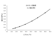
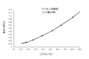
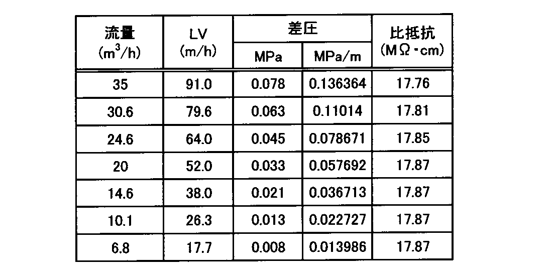
濃度8mg/Lの食塩水溶液(27℃)を上向流にて通水した。この際、上向流速LVを0m/hから91.0m/hまで30minかけて徐々に増大させ、差圧の経時変化を測定した。結果を表1及び図5に示す。
また、上向流速LVが91.0m/hに到達した後、0m/hまで30minかけて徐々に減少させ、差圧の経時変化を測定した。結果を表2及び図6に示す。
なお、表1,2には、差圧の測定値(MPa)を充填床高さ(m)で除した値MPa/m(充填床1m当りの差圧)も記載した。

<考察>
表1,2及び図5,6の通り、LVの変化にほぼ比例して差圧が変化することが認められた。なお、LVの変化が20m/h(実験例1における固定床形成時のLV)付近を通過する際においても、差圧はLVの変化にほぼ比例して変化した。
表1,2及び図5,6の通り、LVの変化にほぼ比例して差圧が変化することが認められた。なお、LVの変化が20m/h(実験例1における固定床形成時のLV)付近を通過する際においても、差圧はLVの変化にほぼ比例して変化した。
[実験例3]
<実験方法>
実験例1で用いたものと同一構成のアニオン交換塔23を構成した。
<実験方法>
実験例1で用いたものと同一構成のアニオン交換塔23を構成した。
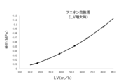
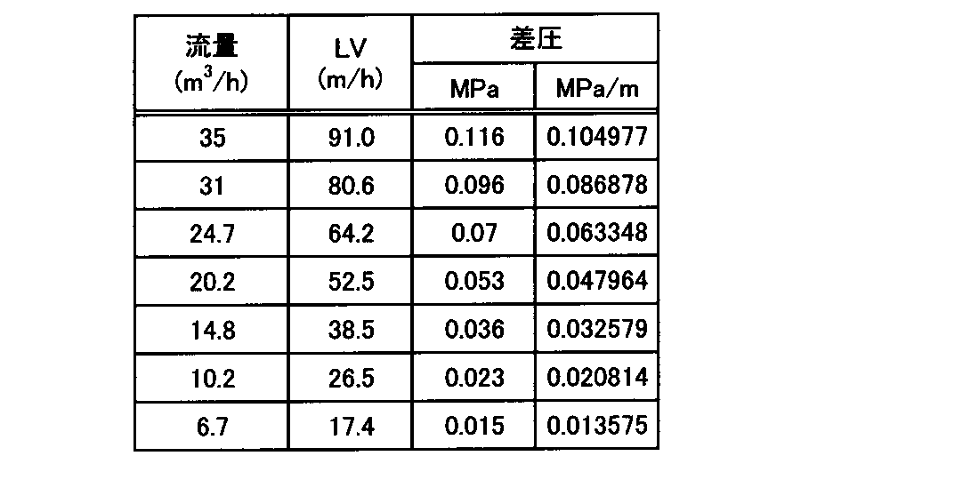
濃度8mg/Lの食塩水溶液(27.6℃)を上向流にて通水した。この際、上向流速LVを0m/hから91.0m/hまで30minかけて徐々に増大させ、差圧の経時変化を測定した。結果を表3及び図7に示す。
また、上向流速LVが91.0m/hに到達した後、0m/hまで30minかけて徐々に減少させ、差圧の経時変化を測定した。結果を表4及び図8に示す。
なお、表3,4には、差圧の測定値(MPa)を充填床高さ(m)で除した値MPa/m(充填床1m当りの差圧)も記載した。

<考察>
表3,4及び図7,8の通り、LVの変化にほぼ比例して差圧が変化することが認められた。なお、LVの変化が20m/h(実験例1における固定床形成時のLV)付近を通過する際においても、差圧はLVの変化にほぼ比例して変化した。
表3,4及び図7,8の通り、LVの変化にほぼ比例して差圧が変化することが認められた。なお、LVの変化が20m/h(実験例1における固定床形成時のLV)付近を通過する際においても、差圧はLVの変化にほぼ比例して変化した。
[実験例4-1,4-2]
<実験例4-1>
内径40mm、高さ1000mmのカラムを2本用意し、一方のカラムにH型カチオン樹脂500mLを充填した(充填床高さ≒400mm)。他方のカラムにOH型アニオン樹脂を1000mL充填した(充填床高さ≒800mm)。これらのカラムを、カチオン充填カラム⇒アニオン充填カラムの順で上向流で通液が行われるように配管で接続した。H型カチオン交換樹脂は、Na型のカチオン交換樹脂を再生したものであり、平均粒径は650μmである。OH型アニオン交換樹脂は、Cl型のアニオン交換樹脂を再生したものであり、平均粒径は550μmである。
<実験例4-1>
内径40mm、高さ1000mmのカラムを2本用意し、一方のカラムにH型カチオン樹脂500mLを充填した(充填床高さ≒400mm)。他方のカラムにOH型アニオン樹脂を1000mL充填した(充填床高さ≒800mm)。これらのカラムを、カチオン充填カラム⇒アニオン充填カラムの順で上向流で通液が行われるように配管で接続した。H型カチオン交換樹脂は、Na型のカチオン交換樹脂を再生したものであり、平均粒径は650μmである。OH型アニオン交換樹脂は、Cl型のアニオン交換樹脂を再生したものであり、平均粒径は550μmである。
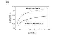
カチオン交換樹脂の充填床の下側及びカラム上部と、アニオン交換樹脂の充填床の下側及びカラム上部に、それぞれ透水性仕切板を配置した。8mg/Lの食塩水溶液(27℃)をLV=50m/hで10min通水して各イオン交換樹脂床を押し上げ、各カラム内に固定床を形成した後、固定床が維持されるLV=20m/hで食塩水溶液を通水した。このLV=20m/hでの通水開始後の比抵抗の経時変化を図9に示す。
<実験例4-2>
実験例4-1において、固定床を形成することなく、前記食塩水溶液をLV=20m/hで通水を行った。通水開始後の比抵抗の経時変化を図9に示す。
実験例4-1において、固定床を形成することなく、前記食塩水溶液をLV=20m/hで通水を行った。通水開始後の比抵抗の経時変化を図9に示す。
<考察>
図9の通り、固定床を形成した実施例4-1の場合、固定床を形成しなかった実施例4-2の場合よりも比抵抗が約1MΩ・cm高くなることが認められた。
図9の通り、固定床を形成した実施例4-1の場合、固定床を形成しなかった実施例4-2の場合よりも比抵抗が約1MΩ・cm高くなることが認められた。
本発明を特定の態様を用いて詳細に説明したが、本発明の意図と範囲を離れることなく様々な変更が可能であることは当業者に明らかである。
本出願は、2023年8月3日付で出願された日本特許出願2023-127186に基づいており、その全体が引用により援用される。
本出願は、2023年8月3日付で出願された日本特許出願2023-127186に基づいており、その全体が引用により援用される。
3,3’ イオン交換装置
7 流量調整バルブ
9 純水タンク
11 流量計又は圧力計
12 水位計
13 制御器
14 圧力計
21 カチオン交換塔
21a,21b 透水性仕切板
22 カチオン交換樹脂
23 アニオン交換塔
23a,23b 透水性仕切板
24 アニオン交換樹脂
30 カチオン交換塔
30a,30b,30c 透水性仕切板
31,32 カチオン交換樹脂
40 脱炭酸塔
50 アニオン交換塔
50a,50b,50c 透水性仕切板
51,52 アニオン交換樹脂
7 流量調整バルブ
9 純水タンク
11 流量計又は圧力計
12 水位計
13 制御器
14 圧力計
21 カチオン交換塔
21a,21b 透水性仕切板
22 カチオン交換樹脂
23 アニオン交換塔
23a,23b 透水性仕切板
24 アニオン交換樹脂
30 カチオン交換塔
30a,30b,30c 透水性仕切板
31,32 カチオン交換樹脂
40 脱炭酸塔
50 アニオン交換塔
50a,50b,50c 透水性仕切板
51,52 アニオン交換樹脂
Claims (3)
- 下側の透水性仕切板と上側の透水性仕切板との間にイオン交換樹脂の充填床を有するイオン交換塔に、給水ポンプによって原水を上向流にて通水して脱イオン水を製造する上向流式イオン交換塔の運転方法であって、
通水開始当初に、イオン交換塔内に高LVにて原水を通水して、該イオン交換塔内のイオン交換樹脂の充填床を押し上げ、該充填床の上側の透水性仕切板に押し当ててイオン交換樹脂の固定床を形成する固定床形成工程と、
その後、該固定床が維持される最小LVよりも大きいLVにて原水を通水し、かつ脱イオン水の需要量に応じて原水の通水量を制御する定常運転工程と
を有する上向流式イオン交換塔の運転方法。 - 前記定常運転工程においては、前記イオン交換塔からの脱イオン水を流量調整バルブを介して脱イオン水タンクに導入し、該脱イオン水タンクから脱イオン水を脱イオン水の需要先に送水する上向流式イオン交換塔の運転方法であって、
該脱イオン水タンク内の水位が所定範囲となるように、かつ前記イオン交換塔の固定床が維持されるように、該流量調整バルブの開度及び/又は前記給水ポンプを制御する請求項1の上向流式イオン交換塔の運転方法。 - 前記給水ポンプの制御頻度が7回/min以下である請求項2の上向流式イオン交換塔の運転方法。
Priority Applications (2)
| Application Number | Priority Date | Filing Date | Title |
|---|---|---|---|
| KR1020257036347A KR20260046019A (ko) | 2023-08-03 | 2024-06-25 | 상향류식 이온 교환탑의 운전 방법 |
| CN202480044300.1A CN121463997A (zh) | 2023-08-03 | 2024-06-25 | 向上流式离子交换塔的运转方法 |
Applications Claiming Priority (2)
| Application Number | Priority Date | Filing Date | Title |
|---|---|---|---|
| JP2023127186A JP7593448B1 (ja) | 2023-08-03 | 2023-08-03 | 上向流式イオン交換塔の運転方法 |
| JP2023-127186 | 2023-08-03 |
Publications (1)
| Publication Number | Publication Date |
|---|---|
| WO2025028080A1 true WO2025028080A1 (ja) | 2025-02-06 |
Family
ID=93655312
Family Applications (1)
| Application Number | Title | Priority Date | Filing Date |
|---|---|---|---|
| PCT/JP2024/022959 Pending WO2025028080A1 (ja) | 2023-08-03 | 2024-06-25 | 上向流式イオン交換塔の運転方法 |
Country Status (5)
| Country | Link |
|---|---|
| JP (1) | JP7593448B1 (ja) |
| KR (1) | KR20260046019A (ja) |
| CN (1) | CN121463997A (ja) |
| TW (1) | TW202508709A (ja) |
| WO (1) | WO2025028080A1 (ja) |
Citations (12)
| Publication number | Priority date | Publication date | Assignee | Title |
|---|---|---|---|---|
| JPS4978680A (ja) * | 1972-12-05 | 1974-07-29 | ||
| JPS5177583A (ja) * | 1974-12-28 | 1976-07-05 | Kurita Water Ind Ltd | |
| JPS60132693A (ja) * | 1983-12-20 | 1985-07-15 | Nippon Paint Co Ltd | 脱イオン装置 |
| JPH08309208A (ja) * | 1995-05-17 | 1996-11-26 | Japan Organo Co Ltd | イオン交換装置 |
| JPH0957116A (ja) * | 1995-08-25 | 1997-03-04 | Ebara Corp | 向流再生式イオン交換装置とその再生方法 |
| JPH09117676A (ja) * | 1995-10-27 | 1997-05-06 | Ebara Corp | 向流再生式イオン交換装置とその再生方法 |
| JP2000503889A (ja) * | 1996-01-26 | 2000-04-04 | ハイドロマティックス,インコーポレイテッド | 廃水の排出量を最小限にする方法及び装置 |
| JP2003088765A (ja) * | 2001-09-19 | 2003-03-25 | Nippon Rensui Co Ltd | 向流再生式イオン交換装置および当該装置におけるイオン交換樹脂の充填層の洗浄方法 |
| JP2003190946A (ja) * | 2001-12-26 | 2003-07-08 | Miura Co Ltd | 水処理装置 |
| JP2012086124A (ja) * | 2010-10-18 | 2012-05-10 | Kurita Water Ind Ltd | 超純水製造方法 |
| US20160137532A1 (en) * | 2014-11-14 | 2016-05-19 | Filterboxx Water And Environmental Corp. | Ion-exchange purification method and apparatus |
| WO2023119747A1 (ja) * | 2021-12-23 | 2023-06-29 | 栗田工業株式会社 | 混合イオン交換樹脂の分離塔、およびこれを用いた混合イオン交換樹脂の分離方法 |
-
2023
- 2023-08-03 JP JP2023127186A patent/JP7593448B1/ja active Active
-
2024
- 2024-06-25 CN CN202480044300.1A patent/CN121463997A/zh active Pending
- 2024-06-25 KR KR1020257036347A patent/KR20260046019A/ko active Pending
- 2024-06-25 WO PCT/JP2024/022959 patent/WO2025028080A1/ja active Pending
- 2024-07-02 TW TW113124608A patent/TW202508709A/zh unknown
Patent Citations (12)
| Publication number | Priority date | Publication date | Assignee | Title |
|---|---|---|---|---|
| JPS4978680A (ja) * | 1972-12-05 | 1974-07-29 | ||
| JPS5177583A (ja) * | 1974-12-28 | 1976-07-05 | Kurita Water Ind Ltd | |
| JPS60132693A (ja) * | 1983-12-20 | 1985-07-15 | Nippon Paint Co Ltd | 脱イオン装置 |
| JPH08309208A (ja) * | 1995-05-17 | 1996-11-26 | Japan Organo Co Ltd | イオン交換装置 |
| JPH0957116A (ja) * | 1995-08-25 | 1997-03-04 | Ebara Corp | 向流再生式イオン交換装置とその再生方法 |
| JPH09117676A (ja) * | 1995-10-27 | 1997-05-06 | Ebara Corp | 向流再生式イオン交換装置とその再生方法 |
| JP2000503889A (ja) * | 1996-01-26 | 2000-04-04 | ハイドロマティックス,インコーポレイテッド | 廃水の排出量を最小限にする方法及び装置 |
| JP2003088765A (ja) * | 2001-09-19 | 2003-03-25 | Nippon Rensui Co Ltd | 向流再生式イオン交換装置および当該装置におけるイオン交換樹脂の充填層の洗浄方法 |
| JP2003190946A (ja) * | 2001-12-26 | 2003-07-08 | Miura Co Ltd | 水処理装置 |
| JP2012086124A (ja) * | 2010-10-18 | 2012-05-10 | Kurita Water Ind Ltd | 超純水製造方法 |
| US20160137532A1 (en) * | 2014-11-14 | 2016-05-19 | Filterboxx Water And Environmental Corp. | Ion-exchange purification method and apparatus |
| WO2023119747A1 (ja) * | 2021-12-23 | 2023-06-29 | 栗田工業株式会社 | 混合イオン交換樹脂の分離塔、およびこれを用いた混合イオン交換樹脂の分離方法 |
Also Published As
| Publication number | Publication date |
|---|---|
| JP2025022521A (ja) | 2025-02-14 |
| JP7593448B1 (ja) | 2024-12-03 |
| KR20260046019A (ko) | 2026-04-06 |
| TW202508709A (zh) | 2025-03-01 |
| CN121463997A (zh) | 2026-02-03 |
Similar Documents
| Publication | Publication Date | Title |
|---|---|---|
| JP5308645B2 (ja) | 陽イオン性不純物を含むアルコールの精製方法 | |
| JP7593448B1 (ja) | 上向流式イオン交換塔の運転方法 | |
| JP7184152B1 (ja) | 混合イオン交換樹脂の分離塔、およびこれを用いた混合イオン交換樹脂の分離方法 | |
| TWI907566B (zh) | 超純水製造系統及超純水製造方法 | |
| TWI551336B (zh) | Ion exchange device, ion exchange resin layer forming method and device | |
| JP7533691B1 (ja) | イオン交換システム及び超純水製造装置 | |
| WO1999050190A1 (en) | Method and device for treating manganese containing water | |
| US5126052A (en) | Condensate polishing system incorporating a membrane filter | |
| JPH034394Y2 (ja) | ||
| JP7405066B2 (ja) | 超純水製造装置及び超純水製造方法 | |
| JP6105879B2 (ja) | 脱炭酸処理装置 | |
| CN104445735B (zh) | 一种双氧水工业中废水的处理方法 | |
| JP7758068B2 (ja) | 混合イオン交換樹脂の分離塔、およびこれを用いた混合イオン交換樹脂の分離方法 | |
| JP3458317B2 (ja) | イオン交換装置及びイオン交換樹脂の再生方法 | |
| JP3162616B2 (ja) | 向流式イオン交換塔の再生方法 | |
| JP7831532B1 (ja) | 純水製造システムの制御方法 | |
| JP2001269668A (ja) | 純水の製造方法および純水の製造装置 | |
| JP2004141805A (ja) | 超純水の製造方法 | |
| JP7847247B2 (ja) | 水処理方法及び水処理装置 | |
| US20250346507A1 (en) | Silicate ion removal device, silicate ion removal system, and silicate ion removal method | |
| JP2014213263A (ja) | 再生型イオン交換装置の運転方法 | |
| JPH05138180A (ja) | 水道水の処理方法 | |
| JP2024139374A (ja) | 水処理システム及び水処理方法 | |
| JP2009090227A (ja) | 凝集ろ過処理方法および凝集ろ過処理装置 | |
| CN119528287A (zh) | 混床系统及水处理方法 |
Legal Events
| Date | Code | Title | Description |
|---|---|---|---|
| 121 | Ep: the epo has been informed by wipo that ep was designated in this application |
Ref document number: 24848740 Country of ref document: EP Kind code of ref document: A1 |
|
| NENP | Non-entry into the national phase |
Ref country code: DE |