WO2025023236A1 - ワイヤー用固定具 - Google Patents
ワイヤー用固定具 Download PDFInfo
- Publication number
- WO2025023236A1 WO2025023236A1 PCT/JP2024/026273 JP2024026273W WO2025023236A1 WO 2025023236 A1 WO2025023236 A1 WO 2025023236A1 JP 2024026273 W JP2024026273 W JP 2024026273W WO 2025023236 A1 WO2025023236 A1 WO 2025023236A1
- Authority
- WO
- WIPO (PCT)
- Prior art keywords
- ball member
- wire
- hole
- medical
- medical wire
- Prior art date
- Legal status (The legal status is an assumption and is not a legal conclusion. Google has not performed a legal analysis and makes no representation as to the accuracy of the status listed.)
- Pending
Links
Images




Classifications
-
- A—HUMAN NECESSITIES
- A61—MEDICAL OR VETERINARY SCIENCE; HYGIENE
- A61B—DIAGNOSIS; SURGERY; IDENTIFICATION
- A61B17/00—Surgical instruments, devices or methods
- A61B17/56—Surgical instruments or methods for treatment of bones or joints; Devices specially adapted therefor
- A61B17/58—Surgical instruments or methods for treatment of bones or joints; Devices specially adapted therefor for osteosynthesis, e.g. bone plates, screws or setting implements
Definitions
- the present invention relates to wire fixing devices and the like used in the medical field.
- a Kirschner wire known as a "K-wire”
- K-wire a Kirschner wire
- the Kirschner wire may be left straight on the insertion side or bent into an L-shape and exposed to the surface of the body so that it can be easily removed in an outpatient setting after bone union has been achieved. It may also be bent into an L-shape and buried subcutaneously so that it can be removed through a small incision.
- the insertion side of the Kirschner wire is left straight or bent into an L-shape and exposed to the body surface after treatment, there is a risk that the Kirschner wire will be pushed into the bone from the insertion side and go deeper than its original position immediately after insertion. In such cases, there is a risk that the Kirschner wire will be difficult to remove, or that the sharp tip of the Kirschner wire will penetrate the bone and blindly damage the tissue beyond.
- the insertion side of the Kirschner wire is bent into an L-shape and exposed to the body surface, there is a risk that the L-shaped part will get caught and the Kirschner wire will be pulled out.
- the Kirschner wire will be pushed inward by force from the outer surface of the skin, and the L-shaped part may interfere with and damage the surrounding soft tissues such as blood vessels, nerves, and tendons.
- Patent Document 1 describes an internal fixator for fracture treatment used in fracture treatment.
- This internal fixator for fracture treatment includes a Kirschner wire that is passed through the treatment target area so as to straddle the fracture site, a pair of staplers that hold both ends of the Kirschner wire, and a screw set that fixes both ends of the Kirschner wire on the staplers by mechanical means.
- the present invention was made in consideration of these circumstances, and aims to realize a wire fastener that is attached to a medical wire that is inserted into bone, and that is less likely to cause damage to soft tissue, such as blood vessels, nerves, or tendons, even when such soft tissue is present near the attachment point.
- the first invention is a wire fixing device that is attached to a medical wire to fix the position of the medical wire inserted into a bone, and includes a ball member formed in a ball shape and having a penetration portion extending in the thickness direction as a portion through which the medical wire passes, and the ball member is attached to the medical wire by crushing the ball member and sandwiching the medical wire with the inner surface of the penetration portion while the medical wire passes through the penetration portion.
- the second invention is the first invention, in which one or more protrusions are formed on the inner surface of the penetration portion.
- the third invention is the first invention, in which a pair of projections and recesses are formed on the inner surface of the through-hole in areas that face each other when viewed from the front of the through-hole.
- the fourth invention is the third invention, in which a pair of concave and convex portions face each other in the short direction of the through portion when viewed from the front.
- the fifth invention is the first invention, in which the ball member has a plurality of pointed protrusions formed on the back surface where one end of the penetration portion opens.
- the sixth invention is the first invention, in which the ball member is formed with a thickness dimension smaller than the minimum dimension of its outer shape when viewed from the front.
- the seventh invention is the sixth invention, in which the ball member is formed in an oblate spheroid shape, and the through-hole is a through-hole extending in the minor axis direction.
- the ball member is attached to the medical wire by the simple task of crushing the ball member and clamping the medical wire with the inner surface of its penetration part. Even if soft tissue such as blood vessels, nerves, tendons, etc. is present near the attachment point of the ball member, the ball member is formed in a ball shape, so the soft tissue is unlikely to be damaged even if the ball member comes into contact with the soft tissue. According to the present invention, it is possible to realize a wire fixture that is attached to a medical wire that is inserted into bone and that is unlikely to cause damage to soft tissue even if soft tissue is present near the attachment point.
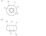
- FIG. 1(A) is a front view of a ball member of a wire fastener according to this embodiment, seen from the front side
- FIG. 1(B) is a side view of the ball member
- FIG. 1(C) is a front view of a ball member of a different form from that of FIG. 1(A).
- 2A and 2B are diagrams for explaining a method of using the wire fastener according to this embodiment, in which FIG. 2A shows the state in which the insertion of the medical wire into the bone has been completed, FIG. 2B shows the state in which the ball member has been moved to a position in which it contacts the outer surface of the bone, FIG. 2C shows the state in which the ball member is being crimped with pliers, and FIG.
- FIG. 3A is a bottom view of a ball member according to a first modified example of the present embodiment
- FIG. 3B is a side view of the ball member.
- FIG. 4 is a side view of a ball member according to a second modified example of the present embodiment.
- FIG. 5 is a perspective view of a ball member according to a third modified example of the present embodiment.
- FIG. 6(A) is a front view of the ball member shown in Figure 5
- Figure 6(B) is a side view of the ball member seen from below in Figure 6(A)
- Figure 6(C) is a side view of the ball member seen from the right side in Figure 6(A)
- Figure 6(D) is a cross-sectional view of the ball member at the A-A cutting position in Figure 6(A)
- Figure 6(E) is a cross-sectional view at a position corresponding to the A-A cutting position for a ball member in which the direction in which the convex portions are continuously arranged is different from that in Figure 6(A).
- FIG. 7 is a diagram showing a state in which a wire fixture according to Modification 4 of the present embodiment is attached to a medical wire.
- This embodiment is a wire fixing device 10 that is attached to a medical wire 5 (such as a Kirschner wire) to fix the position of the medical wire 5 inserted into a bone 8.
- the wire fixing device 10 is used during treatment or surgery such as percutaneous pinning or open reduction and fixation.
- the wire fixing device 10 is provided with one ball-shaped ball member 11 with a smooth outer surface for one medical wire 5.
- the ball member 11 is made of a material (stainless steel, titanium, etc.) that is medically acceptable for being embedded subcutaneously and that undergoes plastic deformation when an external force is applied.
- spherical is not limited to a perfect sphere, but means a sphere, an ellipsoid, or a similar shape.
- the ball member 11 is formed as a rounded, integral piece with no corners, except for the edge of the opening of the through-hole 12.
- the outer periphery of the ball member 11 in front view is composed only of curves (see FIG. 1(A)), and the outer periphery of the ball member 11 is rounded in cross section over its entire length.
- the ball member 11 is formed in an oblate spheroid shape.
- the ball member 11 has a flattened spheroid shape with its minor axis extending in the thickness direction.
- the ball member 11 is formed so that the minimum dimension L of the outer shape in the front view shown in FIG. 1(A) is larger than the thickness dimension D (see FIG. 1(B)).
- the minimum dimension L of the outer shape is the diameter of the ball member 11.
- the minimum dimension L of the outer shape is the horizontal dimension (width dimension) perpendicular to the longitudinal direction.
- the minimum dimension L of the outer shape can be 1.5 times or more the thickness dimension D.
- the minimum dimension L of the outer shape is 3 times or more the thickness dimension D.
- the ball member 11 has a through hole 12 extending in the thickness direction (short axis direction) as a penetration portion through which the medical wire 5 passes.
- the ball member 11 has a ring shape (or doughnut shape) due to the through hole 12.
- the through hole 12 can be, for example, a circular hole.
- the ball member 11 functions as a hollow rivet.
- the penetration portion 12 may have an opening on the side of the ball member 11 as shown in FIG. 1(C). When viewed from the front, the ball member 11 is approximately C-shaped.
- the dimensions of the ball member 11 are standardized in a number of dimensions so that they can be used according to the diameter of the medical wire 5.
- Medical wires 5 that are generally used are 0.7 mm to 2.4 mm.
- the minimum external dimension L of the ball member 11 when viewed from the front (diameter in this embodiment) can be, for example, 1.5 mm to 8 mm.
- the thickness D of the ball member 11 can be, for example, 1 mm to 5 mm.
- the diameter r of the through hole 12 is slightly larger than the diameter of the medical wire 5, and can be, for example, 0.8 mm to 2.8 mm.
- the medical wire 5 is passed through the through hole 12 of the ball member 11, and as shown in FIG. 2(B), the ball member 11 is moved to a position where the back surface (or front surface) of the ball member 11 comes into contact with the outer surface of the bone 8. Then, in this state, as shown in FIG. 2(C), a tool P such as pliers is used to grasp the side of the ball member 11, and from this state, the ball member 11 is crushed to pinch the medical wire 5 between the inner surfaces of the through hole 12 (the opposing inner surfaces) (i.e., the ball member 11 is crimped), and the ball member 11 is attached (fixed) to the medical wire 5.
- the ball member 11 plays the role of a "barb.”
- a tool P such as pliers is used to cut off the base of the portion of the medical wire 5 that protrudes from the through-hole 12 of the ball member 11.
- the medical wire 5 is cut directly above the ball member 11.
- the skin is sutured and the surgery is completed. Note that the skin is not shown in FIG. 2.
- the ball member 11 is attached to the medical wire 5 by crushing the ball member 11 with a tool P such as pliers at a position where the back (or front) of the ball member 11 contacts the outer surface of the skin, and pinching the medical wire 5 with the inner surface of the through-hole 12. Then, the medical wire 5 is cut directly above the ball member 11, and the treatment is completed.
- a tool P such as pliers
- the ball member 11 is attached to the medical wire 5 by a simple operation of crimping the ball member 11, and the ball member 11 can be easily fixed at the very edge of the insertion portion (the position where the ball member 11 contacts the outer surface of the bone 8 or the outer surface of the skin).
- the position of the medical wire 5 is fixed by the ball member 11.
- the medical wire 5 is less likely to shift from the initial insertion position.
- the medical wire 5 is cut so that the stump of the medical wire 5 hardly protrudes from the ball member 11, so that the ball member 11 is caught and the medical wire 5 is less likely to come out. According to this embodiment, it is possible to prevent a decrease in the fixing force fixing the bone 8 and the breakage of the fixed bone 8 caused by the positional deviation of the medical wire 5.
- the ball member 11 even if soft tissue such as blood vessels, nerves, or tendons is present near the attachment location of the ball member 11, the ball member 11 is formed in a ball shape, and therefore the soft tissue is unlikely to be damaged even if the ball member 11 comes into contact with the soft tissue.
- a plurality of projections 15 with pointed tips are formed on the back surface 11b of the ball member 11 (the surface where one end of the through hole 12 opens).
- the plurality of projections 15 are arranged in the vicinity of the through hole 12 and lined up in the circumferential direction of the through hole 12.
- Each projection 15 is formed in a stud shape.
- the dimensions of each projection 15 may be about 1 mm in diameter (diameter of the bottom) and about 1 mm in height.
- the number of projections 15 may be, for example, three or more.
- the medical wire 5 is passed through the through hole 12 of the ball member 11 so that the back surface 11b of the ball member 11 faces the bone 8. After the ball member 11 is crimped and attached to the medical wire 5, the ball member 11 is pushed toward the bone 8 and each protrusion 15 is driven into the bone 8.
- the medical wire 5 when the medical wire 5 is inserted, the medical wire 5 may bend. In such a case, if the medical wire 5 rotates, it will affect the stability of the fixed bone 8. In this modified example, the protrusions 15 prevent the medical wire 5 from rotating. Therefore, it is possible to reduce the effect on the stability of the fixed bone 8.
- the shape of the ball member 11 in a side view is different from that of the embodiment.
- the curvature of the outer periphery 11y on the back side is larger than the curvature of the outer periphery 11x on the front side. Therefore, the contact area of the ball member 11 with the bone 8 is larger.
- one or more protrusions 21 are provided protruding from the inner surface of the through hole 12 of the ball member 11.
- an uneven portion 25 consisting of a plurality of continuous protrusions 21 (e.g., three or more protrusions 21) is formed on the inner surface of the through hole 12.
- the through portion 12 may have an opening on the side surface of the ball member 11 as shown in Figure 1(C).
- each convex portion 21 in the uneven portion 25 is formed in a tapered shape (for example, a triangular shape with the base at the base), and the tip of each convex portion 21 is sharp.
- the uneven portion 25 has a jagged shape.
- each convex portion 21 is formed along the penetrating direction of the through hole 12 (thickness direction of the ball member 11).
- a pair of uneven portions 25 are formed on the inner surface of the through hole 12 in areas that face each other when viewed from the front of the through hole 12.
- the through hole 12 is formed horizontally long when viewed from the front as shown in FIG. 6(A).
- the front shape of the through hole 12 has a longitudinal direction and a lateral direction that intersects with the longitudinal direction (e.g., a direction perpendicular to the longitudinal direction).
- the lateral dimension of the through hole 12 is slightly larger than the diameter of the medical wire 5.
- the pair of uneven portions 25 face each other in the lateral direction of the through hole 12 when viewed from the front.
- the present invention can be applied to wire fixing devices used in the medical field.
Landscapes
- Health & Medical Sciences (AREA)
- Life Sciences & Earth Sciences (AREA)
- Orthopedic Medicine & Surgery (AREA)
- Surgery (AREA)
- Biomedical Technology (AREA)
- Engineering & Computer Science (AREA)
- Nuclear Medicine, Radiotherapy & Molecular Imaging (AREA)
- Heart & Thoracic Surgery (AREA)
- Medical Informatics (AREA)
- Molecular Biology (AREA)
- Animal Behavior & Ethology (AREA)
- General Health & Medical Sciences (AREA)
- Public Health (AREA)
- Veterinary Medicine (AREA)
- Surgical Instruments (AREA)
Priority Applications (1)
| Application Number | Priority Date | Filing Date | Title |
|---|---|---|---|
| JP2025531896A JP7745949B2 (ja) | 2023-07-25 | 2024-07-23 | ワイヤー用固定具 |
Applications Claiming Priority (2)
| Application Number | Priority Date | Filing Date | Title |
|---|---|---|---|
| JP2023-121164 | 2023-07-25 | ||
| JP2023121164 | 2023-07-25 |
Publications (1)
| Publication Number | Publication Date |
|---|---|
| WO2025023236A1 true WO2025023236A1 (ja) | 2025-01-30 |
Family
ID=94375311
Family Applications (1)
| Application Number | Title | Priority Date | Filing Date |
|---|---|---|---|
| PCT/JP2024/026273 Pending WO2025023236A1 (ja) | 2023-07-25 | 2024-07-23 | ワイヤー用固定具 |
Country Status (2)
| Country | Link |
|---|---|
| JP (1) | JP7745949B2 (https=) |
| WO (1) | WO2025023236A1 (https=) |
Citations (7)
| Publication number | Priority date | Publication date | Assignee | Title |
|---|---|---|---|---|
| JPH08322849A (ja) * | 1995-05-24 | 1996-12-10 | Jean Jacques Martin | 骨に固定されるピンのための保持器具 |
| JP2002306498A (ja) * | 2001-04-12 | 2002-10-22 | Tsunenori Takei | 手術器具 |
| JP3106970U (ja) * | 2004-08-02 | 2005-01-27 | 株式会社アクセサリーマルタカ | ワイヤー留め金具およびこれを用いた吊り下げワイヤー |
| WO2013105972A1 (en) * | 2012-01-13 | 2013-07-18 | A.M. Surgical, Inc. | Cross pin fixator for bone fragments and use thereof |
| KR101587456B1 (ko) * | 2015-09-22 | 2016-01-21 | (주)올소테크 | 뼈 고정용 치료기구 |
| WO2016157852A1 (ja) * | 2015-04-01 | 2016-10-06 | 株式会社AimedicMMT | 外科用ケーブルの締結器及びその製造方法 |
| JP6616767B2 (ja) | 2014-04-21 | 2019-12-04 | 学校法人 久留米大学 | 骨折治療用内固定器 |
-
2024
- 2024-07-23 JP JP2025531896A patent/JP7745949B2/ja active Active
- 2024-07-23 WO PCT/JP2024/026273 patent/WO2025023236A1/ja active Pending
Patent Citations (7)
| Publication number | Priority date | Publication date | Assignee | Title |
|---|---|---|---|---|
| JPH08322849A (ja) * | 1995-05-24 | 1996-12-10 | Jean Jacques Martin | 骨に固定されるピンのための保持器具 |
| JP2002306498A (ja) * | 2001-04-12 | 2002-10-22 | Tsunenori Takei | 手術器具 |
| JP3106970U (ja) * | 2004-08-02 | 2005-01-27 | 株式会社アクセサリーマルタカ | ワイヤー留め金具およびこれを用いた吊り下げワイヤー |
| WO2013105972A1 (en) * | 2012-01-13 | 2013-07-18 | A.M. Surgical, Inc. | Cross pin fixator for bone fragments and use thereof |
| JP6616767B2 (ja) | 2014-04-21 | 2019-12-04 | 学校法人 久留米大学 | 骨折治療用内固定器 |
| WO2016157852A1 (ja) * | 2015-04-01 | 2016-10-06 | 株式会社AimedicMMT | 外科用ケーブルの締結器及びその製造方法 |
| KR101587456B1 (ko) * | 2015-09-22 | 2016-01-21 | (주)올소테크 | 뼈 고정용 치료기구 |
Also Published As
| Publication number | Publication date |
|---|---|
| JPWO2025023236A1 (https=) | 2025-01-30 |
| JP7745949B2 (ja) | 2025-09-30 |
Similar Documents
| Publication | Publication Date | Title |
|---|---|---|
| JP7383653B2 (ja) | 骨固定装置および方法 | |
| US6585739B2 (en) | Apparatus for attaching a cranial flap | |
| AU2002309204B2 (en) | Surgical staple | |
| US8597326B2 (en) | Suturing needle | |
| US20060241624A1 (en) | Bone fixation device for surgical operation, cutting device and band head for the same | |
| CN107028650B (zh) | 骨折固定夹具 | |
| CN102413780B (zh) | 用于骨环扎的微创压折器和缆线的系统和方法 | |
| US20040176783A1 (en) | Vascular suturing clip | |
| US8343152B2 (en) | Fixed angle dual prong pin fixation system | |
| AU2002309204A1 (en) | Surgical staple | |
| WO2009084549A1 (ja) | 医療用縫合針 | |
| CN109259844B (zh) | 一种手术缝合装置 | |
| JP7745949B2 (ja) | ワイヤー用固定具 | |
| CN112043370B (zh) | 一种微创插入可弯曲环绕骨骼的钢丝引导器 | |
| JP2007075429A (ja) | 整復鉗子 | |
| CN221555758U (zh) | 一种吻合钉 | |
| US20210196259A1 (en) | Method and apparatus for supporting a u-shaped portion of an elongate flexible element relative to a human body tissue | |
| US11324539B2 (en) | Method of placing a bone implant in an operative position with respect to a bone part | |
| JPH1052439A (ja) | アンカーネイル並びにアンカースクリュー及びその打ち 込み器 | |
| EP1629781A2 (en) | Suture thread with needle | |
| JP6522562B2 (ja) | 外科用治具及び外科用骨固定ユニット | |
| JP2000023991A (ja) | 超音波トラカール | |
| JP2001333909A (ja) | 医療用縫合針 | |
| JP2023127049A (ja) | 骨固定システム | |
| CN223311234U (zh) | 固定器及固定系统 |
Legal Events
| Date | Code | Title | Description |
|---|---|---|---|
| 121 | Ep: the epo has been informed by wipo that ep was designated in this application |
Ref document number: 24845611 Country of ref document: EP Kind code of ref document: A1 |
|
| DPE1 | Request for preliminary examination filed after expiration of 19th month from priority date (pct application filed from 20040101) | ||
| WWE | Wipo information: entry into national phase |
Ref document number: 2025531896 Country of ref document: JP |
|
| REG | Reference to national code |
Ref country code: BR Ref legal event code: B01A Ref document number: 112026001636 Country of ref document: BR |
|
| WWE | Wipo information: entry into national phase |
Ref document number: 2024845611 Country of ref document: EP |
|
| NENP | Non-entry into the national phase |
Ref country code: DE |
|
| WWE | Wipo information: entry into national phase |
Ref document number: 11202600446Q Country of ref document: SG |
|
| WWP | Wipo information: published in national office |
Ref document number: 11202600446Q Country of ref document: SG |
|
| ENP | Entry into the national phase |
Ref document number: 112026001636 Country of ref document: BR Kind code of ref document: A2 Effective date: 20260123 |