WO2025023231A1 - シート片形成装置及び貼付装置 - Google Patents
シート片形成装置及び貼付装置 Download PDFInfo
- Publication number
- WO2025023231A1 WO2025023231A1 PCT/JP2024/026256 JP2024026256W WO2025023231A1 WO 2025023231 A1 WO2025023231 A1 WO 2025023231A1 JP 2024026256 W JP2024026256 W JP 2024026256W WO 2025023231 A1 WO2025023231 A1 WO 2025023231A1
- Authority
- WO
- WIPO (PCT)
- Prior art keywords
- strip
- sheet
- nip position
- downstream
- cutting blade
- Prior art date
- Legal status (The legal status is an assumption and is not a legal conclusion. Google has not performed a legal analysis and makes no representation as to the accuracy of the status listed.)
- Pending
Links
Images






Classifications
-
- B—PERFORMING OPERATIONS; TRANSPORTING
- B26—HAND CUTTING TOOLS; CUTTING; SEVERING
- B26D—CUTTING; DETAILS COMMON TO MACHINES FOR PERFORATING, PUNCHING, CUTTING-OUT, STAMPING-OUT OR SEVERING
- B26D1/00—Cutting through work characterised by the nature or movement of the cutting member or particular materials not otherwise provided for; Apparatus or machines therefor; Cutting members therefor
- B26D1/01—Cutting through work characterised by the nature or movement of the cutting member or particular materials not otherwise provided for; Apparatus or machines therefor; Cutting members therefor involving a cutting member which does not travel with the work
- B26D1/02—Cutting through work characterised by the nature or movement of the cutting member or particular materials not otherwise provided for; Apparatus or machines therefor; Cutting members therefor involving a cutting member which does not travel with the work having a stationary cutting member
-
- B—PERFORMING OPERATIONS; TRANSPORTING
- B26—HAND CUTTING TOOLS; CUTTING; SEVERING
- B26D—CUTTING; DETAILS COMMON TO MACHINES FOR PERFORATING, PUNCHING, CUTTING-OUT, STAMPING-OUT OR SEVERING
- B26D7/00—Details of apparatus for cutting, cutting-out, stamping-out, punching, perforating, or severing by means other than cutting
- B26D7/06—Arrangements for feeding or delivering work of other than sheet, web, or filamentary form
-
- B—PERFORMING OPERATIONS; TRANSPORTING
- B26—HAND CUTTING TOOLS; CUTTING; SEVERING
- B26D—CUTTING; DETAILS COMMON TO MACHINES FOR PERFORATING, PUNCHING, CUTTING-OUT, STAMPING-OUT OR SEVERING
- B26D7/00—Details of apparatus for cutting, cutting-out, stamping-out, punching, perforating, or severing by means other than cutting
- B26D7/08—Means for treating work or cutting member to facilitate cutting
- B26D7/14—Means for treating work or cutting member to facilitate cutting by tensioning the work
-
- B—PERFORMING OPERATIONS; TRANSPORTING
- B26—HAND CUTTING TOOLS; CUTTING; SEVERING
- B26F—PERFORATING; PUNCHING; CUTTING-OUT; STAMPING-OUT; SEVERING BY MEANS OTHER THAN CUTTING
- B26F3/00—Severing by means other than cutting; Apparatus therefor
- B26F3/02—Tearing
Definitions
- the present invention relates to a technique for forming sheet pieces, such as labels, from a continuous strip of sheet, and a pasting technique using the sheet pieces.
- Patent Document 1 discloses a technique in which the strip is fed out a predetermined length, and then the cutting blade is lowered to cut the strip at perforations and form sheet pieces of a predetermined length.
- the object of the present invention is to make it possible to cut a strip of sheet using a fixed cutting blade in a technology for forming sheet pieces by cutting the strip of sheet.
- the sheet piece forming device of the present invention is a device that uses a strip-shaped sheet in which multiple regions that will become sheet pieces are formed, and enables the formation of sheet pieces in sequence from a leading region at the forefront of the strip-shaped sheet among the multiple regions, and includes a cutting blade fixed at a predetermined position, a pay-out unit, and a delivery unit.
- the pay-out unit is a unit that pays out the strip-shaped sheet from the upstream side of the cutting blade, and includes an upstream nip mechanism that nips the strip-shaped sheet at a position upstream of the cutting blade, and a pay-out drive mechanism that enables the strip-shaped sheet to be paid out from the upstream nip position, which is the nip position by the upstream nip mechanism.
- the delivery unit is a unit that sends out sheet pieces downstream of the cutting blade, and includes a downstream nip mechanism that nips the strip-shaped sheet at a position downstream of the cutting blade, and a retraction drive mechanism that enables the strip-shaped sheet to be retracted into the downstream nip position, which is the nip position by the downstream nip mechanism.
- the predetermined position is a position where the strip of sheet comes into contact with the cutting edge of the cutting blade when the strip of sheet is in a taut state without slack between the upstream nip position and the downstream nip position.
- the above-mentioned sheet piece forming device makes it possible to perform the following control. Specifically, by having the pay-out drive mechanism and the retraction drive mechanism alternately pay out the strip sheet from the upstream nip position and retract the strip sheet to the downstream nip position, it becomes possible to alternately form a slack state in which the strip sheet is slack and a taut state between the upstream nip position and the downstream nip position.
- This configuration allows the strip to transition from a slack state to a taut state, which makes it possible to press the strip against the cutting edge of the cutting blade and cut the strip.
- the retraction drive mechanism may include a guide belt that moves the leading edge of the strip sheet that has been unwound from the upstream nip position to the downstream nip position, and a delivery belt that retracts the leading edge of the strip sheet that has reached the downstream nip position further downstream.
- the above configuration makes it possible to perform the following control. Specifically, after the start of payout of the strip sheet from the upstream nip position, if the leading edge of the strip sheet comes into contact with the stopped guide belt, causing slack in the strip sheet, the guide belt can be made to start moving the leading edge toward the downstream nip position. Thereafter, when the leading edge of the strip sheet reaches the downstream nip position and is pulled further downstream by the feed belt, the payout drive mechanism can be made to stop payout of the strip sheet from the upstream nip position, thereby making it possible to transition the strip sheet from a slack state to a taut state.
- the leading end of the strip sheet (the leading end abutting the guide belt) starts to move toward the downstream nip position after slack occurs in the strip sheet, making it possible to move the leading end of the strip sheet to the downstream nip while maintaining the slack state of the strip sheet. Also, by stopping the payout of the strip sheet from the upstream nip position, the payout of the strip sheet from the upstream nip position is no longer possible, while the retraction of the strip sheet to the downstream nip position continues, making it possible to transition the strip sheet from a slack state to a taut state.
- the strip sheet may be a sheet in which multiple regions are continuously connected via perforations.
- the following control can be performed. Specifically, after cutting the strip sheet at a perforation, it is possible to cause the payout drive mechanism to pay out the length from the perforation to the next perforation between the start and end of payout of the strip sheet.
- the locations of the perforations in the strip sheet are weak locations that are prone to breaking. Therefore, even if the position of the perforations deviates from the position of the cutting blade tip when the strip sheet transitions to a taut state, it is possible to cut the strip sheet at the perforations as long as the deviation is slight.
- the sheet piece forming device may further include a tongue portion that prevents the leading region that is cut by the cutting blade from rolling up. This configuration can prevent the band-shaped sheet from rolling up, and as a result, the formation of the sheet pieces can be performed continuously without interruption.
- the application device includes the sheet piece forming device and a conveying device, and applies the sheet piece formed by the sheet piece forming device to an object conveyed by the conveying device.
- the present invention in a technology for forming sheet pieces by cutting a strip-shaped sheet, it is possible to cut the strip-shaped sheet using a fixed cutting blade.
- FIG. 1A is a front view conceptually showing a bonding device according to an embodiment
- FIG. 1B is a block diagram conceptually showing the bonding device.
- FIG. 2 is a perspective view conceptually showing a strip-shaped film (an example of a strip-shaped sheet) used in a sheet piece forming device provided in the bonding device.
- FIG. 3 is a front view conceptually showing the sheet piece forming device.
- FIG. 4 is a diagram showing a delivery mechanism included in the sheet piece forming apparatus as viewed in the direction of the arrow Dz (see FIG. 1A).
- FIG. 5 is a flow chart showing the control process executed by the control device of the bonding device and the state of the strip of film that changes accordingly.
- FIG. 5 is a flow chart showing the control process executed by the control device of the bonding device and the state of the strip of film that changes accordingly.
- FIG. 6A is a conceptual diagram sequentially showing the operation of the sheet piece forming device and the state of the strip film.
- FIG. 6B is a conceptual diagram sequentially showing the operation of the sheet piece forming device and the state of the strip film.
- FIG. 6C is a conceptual diagram sequentially showing the operation of the sheet piece forming device and the state of the belt-shaped film.
- FIG. 6D is a conceptual diagram sequentially showing the operation of the sheet piece forming device and the state of the strip film.
- FIG. 6E is a conceptual diagram sequentially showing the operation of the sheet piece forming device and the state of the strip film.
- FIG. 6F is a conceptual diagram sequentially showing the operation of the sheet piece forming device and the state of the strip film.
- FIG. 6G is a conceptual diagram sequentially showing the operation of the sheet piece forming device and the state of the strip film.
- FIG. 7 is a conceptual diagram showing a part (a cutting blade and its surrounding area) of a sheet piece forming device according to a first modified example.
- FIGS. 1(A) and 1(B) are a front view and a block diagram conceptually illustrating a bonding device according to an embodiment.
- the bonding device includes a sheet piece forming device 1, a conveying device 2, a bonding mechanism 3, and a control device 4. The configuration of each part will be specifically described below.
- FIG. 2 is a perspective view conceptually showing a strip-shaped film 10 used in the sheet piece forming apparatus 1 of this embodiment.
- the strip-shaped film 10 is a long film in which a plurality of regions Rf are continuously connected via perforations Pm.
- each region Rf is an area that becomes a film piece Qf (such as a label) to be attached to an object 20 (such as a container or a packaged product; see FIG. 1A).
- the film piece Qf is an example of a sheet piece that can be formed by the sheet piece forming apparatus 1, and the sheet piece can be formed not only from the strip-shaped film 10 but also from a strip-shaped sheet formed from a material other than a film (such as paper).
- the strip of film 10 is pre-applied with an adhesive that enables the film piece Qf to be attached to the object 20.
- the adhesive is applied to the entire surface of one side of the strip of film 10. Specifically, the adhesive is applied to the side opposite the side that is sucked by the suction device 131D of the feed unit 13 (see Figures 3 and 4) described below (in other words, the side that comes into contact with the feed belt 131C when held by the feed belt 131C by suction).
- the side to which the adhesive is applied will be referred to as the "adhesive side” below, and the side opposite to that side (the side that is sucked by the suction device 131D) will be referred to as the "rear side.”
- FIG 3 is a perspective view conceptually showing the sheet piece forming device 1.
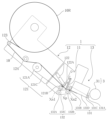
- the sheet piece forming device 1 is a device that enables the formation of film pieces Qf using the above-mentioned strip film 10, starting from the leading region Rft (see Figure 2) at the leading end of the strip film 10 among the multiple regions Rf, and includes a cutting blade 11, a pay-out unit 12, and a delivery unit 13.
- the cutting blade 11 is a cutting blade that cuts the strip film 10.
- the cutting blade 11 is fixed at a predetermined position Xp, and does not require a complicated mechanism for moving it forward and backward. By fixing the cutting blade 11 in this manner, the safety of workers during operation and maintenance of the bonding device is easily ensured.
- the cutting blade 11 only needs to be capable of breaking the strip film 10 at the perforation Pm, and does not need to be sharp enough to cut the strip film 10 at a location where there is no perforation Pm. This makes it possible to further improve safety.
- the details of the predetermined position Xp will be described later.
- the payout unit 12 is a unit that pays out the strip film 10 from the upstream side of the cutting blade 11.
- the payout unit 12 includes a payout drive mechanism 121 and an upstream nip mechanism 122.
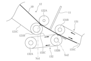
- the payout drive mechanism 121 includes a drive roller 121A, a driven roller 121B, and a payout belt 121C (endless belt) stretched around these rollers, and converts the rotational motion of the drive roller 121A into the orbital motion of the payout belt 121C.
- the driven roller 121B is positioned closer to the cutting blade 11 than the drive roller 121A, and the strip film 10 is paid out from the drive roller 121A to the driven roller 121B by the orbital motion of the payout belt 121C.
- the upstream nip mechanism 122 has a nip roller 122A, and is configured so that the nip roller 122A can be biased toward the driven roller 121B of the pay-out drive mechanism 121 to sandwich the pay-out belt 121C and the strip film 10 between the nip roller 122A and the driven roller 121B.
- This configuration of the pay-out unit 12 makes it possible for the upstream nip mechanism 122 to nip the strip of film 10 at a position upstream of the cutting blade 11, and for the pay-out drive mechanism 121 to pay out the strip of film 10 from the nip position of the upstream nip mechanism 122 (hereinafter referred to as "upstream nip position Xn1").
- the strip film 10 is wound around a core material or the like to form a roll 10R (see also FIG. 2), and the portion pulled out from the roll 10R is guided to the pay-out drive mechanism 121 via a tension roller 123 and a guide roller 124, and then guided over the pay-out belt 121C of the pay-out drive mechanism 121 to the upstream nip position Xn1. Then, by rotating the pay-out belt 121C in this state, the strip film 10 is paid out from the upstream nip position Xn1. In this embodiment, the strip film 10 is paid out so that the adhesive side is in contact with the pay-out belt 121C when it passes over it (in the example of FIG. 1, the adhesive side is facing down).
- the delivery unit 13 is a unit that delivers the film piece Qf formed by cutting with the cutting blade 11 to the downstream side of the cutting blade 11.
- the delivery unit 13 includes a delivery mechanism 131 and a guide mechanism 132.
- the feed mechanism 131 comprises a drive roller 131A, a driven roller 131B, and a feed belt 131C (endless belt) stretched around these rollers, and converts the rotational motion of the drive roller 131A into the orbital motion of the feed belt 131C.
- the feed mechanism 131 further comprises a suction device 131D.
- the suction device 131D holds the film piece Qf formed by cutting with the cutting blade 11 on the feed belt 131C by sucking it from its back side. More specifically, it is as follows.
- FIG 4 is a diagram showing the feed mechanism 131 as viewed from the direction of arrow Dz (see Figure 1 (A)).
- the feed belt 131C includes two endless belts 133 that are smaller than the width of the film piece Qf (the width of the strip film 10), and these endless belts 133 are arranged parallel to and spaced apart from each other.
- the suction device 131D holds the film piece Qf on the two endless belts 133 by sucking the back of the film piece Qf from the area (gap) between the two endless belts 133 and the area outside the two endless belts 133 through the suction port Hv.
- the suction device 131D has multiple slits arranged in the feed direction Dt as the suction port Hv that intersect with the endless belts 133. Therefore, the film strip Qf is held on the delivery belt 131C (two endless belts 133) and delivered from the position of the driven roller 131B (in this embodiment, the downstream nip position Xn2 described below) to the position of the drive roller 131A.
- the guide mechanism 132 is composed of a drive roller 132A, a nip roller 132B (driven roller), and a guide belt 132C (endless belt) stretched over these rollers, and the rotational motion of the drive roller 132A is converted into the orbital motion of the guide belt 132C.
- the guide mechanism 132 is also configured to urge the nip roller 132B toward the driven roller 131B of the feed mechanism 131, thereby sandwiching the guide belt 132C, the strip film 10, and the feed belt 131C between the nip roller 132B and the driven roller 131B.
- the guide mechanism 132 is positioned so that the leading edge of the strip film 10 unwound from the upstream nip position Xn1 abuts against the guide belt 132C. Therefore, when the guide belt 132C is rotated, the leading edge of the strip film 10 abutting against the guide belt 132C moves to the nip position (hereinafter referred to as the "downstream nip position Xn2") formed by the nip roller 132B. At this time, in this embodiment, the adhesive surface of the strip film 10 (the surface that was in contact with the pay-out belt 121C of the pay-out unit 12) comes into contact with the guide belt 132C. In other words, the strip film 10 is guided to the downstream nip position Xn2 with the adhesive surface facing downward.
- the leading edge of the strip film 10 when the leading edge of the strip film 10 reaches the downstream nip position Xn2, the leading edge can be pulled further downstream by the rotation of the delivery belt 131C.
- This allows the strip film 10 to be nipped by the nip roller 132B at a position downstream of the cutting blade 11.
- the back surface of the portion of the strip film 10 that is pulled further downstream from the downstream nip position Xn2 comes into contact with the delivery belt 131C, and the back surface is sucked by the suction device 131D and held by the delivery belt 131C.
- the portion that is pulled downstream is held by the delivery belt 131C with the adhesive surface facing away from the suction device 131D (downward in the example of FIG. 1).
- the mechanism of the guide mechanism 132 configured to urge the nip roller 132B toward the driven roller 131B can be understood as a "downstream nip mechanism” that nips the strip film 10 at a position downstream of the cutting blade 11.
- the mechanisms of the delivery mechanism 131 and the guide mechanism 132 configured to move the leading end of the strip film 10 that contacts the guide belt 132C to the downstream nip position Xn2 and retract the leading end further downstream by the delivery belt 131C can be understood as a "retraction drive mechanism” that enables the strip film 10 to be retracted to the downstream nip position Xn2.
- the predetermined position Xp at which the cutting blade 11 is fixed is a position where the strip film 10 contacts the cutting edge of the cutting blade 11 when the strip film 10 is in a taut state between the upstream nip position Xn1 and the downstream nip position Xn2 without slack (see FIG. 6F).
- the predetermined position Xp is set at a position where the cutting edge of the cutting blade 11 contacts the back surface (the surface opposite to the adhesive surface) of the strip film 10 when the strip film 10 is in a taut state.
- the cutting blade 11 is installed so that the cutting edge does not contact the adhesive surface of the strip film 10. Therefore, when the strip film 10 is in a taut state, the back surface of the strip film 10 is pressed against the cutting edge of the cutting blade 11.
- the conveying device 2 is a device such as a conveyor that enables the conveying of an object 20 (such as a container or a packaged product) (see FIG. 1(A)).
- the conveying device 2 conveys the object 20 through an attachment position where the film piece Qf is attached.
- the adhesive mechanism 3 is a device that adheres the film piece Qf delivered from the delivery unit 13 to the target object 20 (see FIG. 1A).
- the adhesive mechanism 3 has a rotatable press roller 31 installed downstream of the delivery unit 13 (see FIGS. 3 and 4), and is configured to be able to sandwich the film piece Qf between itself and the target object 20 transported by the transport device 2.
- the control device 4 includes a storage unit 41 and a control unit 42 (see FIG. 1(B)).
- the storage unit 41 is a unit that stores information required for controlling the bonding device (such as parameters required for controlling the sheet piece forming device 1 and the conveying device 2), and is composed of storage devices such as ROM and RAM.
- the control unit 42 is a unit that executes control of the bonding device, and is composed of a processing device such as a CPU. Below, the control process executed by the control device 4 in the bonding device will be specifically described.
- the control device 4 may be regarded as one of the components of the sheet piece forming device 1.
- FIG. 5 is a flow chart showing the control process executed by the control device 4 and the state of the film strip 10 that changes as a result of the control process.
- FIGS. 6A to 6G are perspective views sequentially showing the operation of the sheet piece forming device 1 and the state of the film strip 10 that occurs as a result of the control process.
- the control device 4 first controls the unwinding unit 12 to cause the unwinding unit 12 to start unwinding the strip film 10 from the upstream nip position Xn1 (step S101, FIG. 6A). At this time, the direction in which the strip film 10 is unwound from the upstream nip position Xn1 (hereinafter referred to as the "unwinding direction") is adjusted so that the leading end of the strip film 10 can pass in front of the cutting edge of the cutting blade 11. In other words, the unwinding direction is adjusted so that the leading end of the strip film 10 can be unwound without coming into contact with the cutting blade 11.
- the control device 4 causes the unwinding unit 12 to continue unwinding the strip film 10 from the upstream nip position Xn1, thereby causing the leading end of the strip film 10 to abut against the stopped guide belt 132C (see FIG. 6B). This limits the movement of the leading end of the strip film 10 (movement associated with unwinding), while continuing unwinding of the strip film 10 from the upstream nip position Xn1, causing slack in the strip film 10 (see FIG. 6C).
- the incident angle ⁇ d (specifically, the angle between the strip film 10 and the portion of the guide belt 132C opposite the downstream nip position Xn2 with respect to the contact point of the strip film 10) when the leading end of the strip film 10 abuts against the guide belt 132C becomes acute, it is possible to cause slack in the strip film 10 that is curved toward the opposite side to the cutting blade 11.
- the control device 4 causes the payout unit 12 to continue to pay out the strip film 10 from the upstream nip position Xn1, and when the above-mentioned slack occurs in the strip film 10, controls the guide mechanism 132 to start rotating the guide belt 132C (step S102).
- the leading end of the strip film 10 starts to move toward the downstream nip position Xn2 while remaining in contact with the guide belt 132C.
- the rotation speed of the guide belt 132C is set to be the same as the payout speed of the strip film 10 from the upstream nip position Xn1.
- the leading end of the strip film 10 can be moved to the downstream nip position Xn2 while maintaining the slack in the strip film 10.
- control device 4 controls the delivery mechanism 131 to cause the delivery mechanism 131 to start rotating the delivery belt 131C before the leading edge of the strip film 10 reaches the downstream nip position Xn2 (step S103).
- step S103 is executed at the same timing as step S102.
- step S103 when the leading edge of the strip film 10 reaches the downstream nip position Xn2 (see FIG. 6D), the leading edge can move further downstream from the downstream nip position Xn2 (see FIG. 6E).
- step S103 the control device 4 also controls the delivery mechanism 131 to start suction by the suction device 131D so that the leading edge of the strip film 10 that has been pulled into the downstream nip position Xn2 can be held on the delivery belt 131C (in other words, so that the film piece Qf formed by the subsequent cutting by the cutting blade 11 can be held on the delivery belt 131C).
- step S104 the payout of the strip film 10 from the upstream nip position Xn1 is stopped, while the strip film 10 continues to be pulled into the downstream nip position Xn2, so that the strip film 10 can be transitioned from a slack state (slack state) to a taut state (tension state; see FIG. 6F) without slack. Then, when the strip film 10 is in a taut state (see FIG. 6F), the strip film 10 comes into contact with the cutting edge of the cutting blade 11.
- This type of control process allows the strip of film 10 to transition from a slack state to a taut state, which makes it possible to press the strip of film 10 against the cutting edge of the cutting blade 11 and cut the strip of film 10 (see Figure 6G).
- control device 4 causes the unwinding unit 12 to unwind an amount that enables the position of the perforation Pm or a position adjacent thereto to come into contact with the cutting edge of the cutting blade 11 when the strip film 10 is in a taut state (see FIG. 6F) as the unwinding amount between the start of unwinding (step S101) of the strip film 10 and the stop of unwinding (step S104).
- the portion of the strip of film 10 where the perforations Pm are formed is a weak portion that is prone to breaking. Therefore, even if the position of the perforations Pm is misaligned from the position of the tip of the cutting blade 11 when the strip of film 10 is pressed against the tip of the cutting blade 11, as long as the misalignment is slight, the strip of film 10 can be cut at the position of the perforations Pm.
- the film piece Qf formed by cutting with the cutting blade 11 is sent to the application position by the application mechanism 3 (pressing roller 31) by the rotation of the delivery belt 131C.
- the film piece Qf is then sandwiched between the object 20 that has been transported to the application position and the pressing roller 31, and is applied to the object 20 (see FIG. 1 (A)).
- control device 4 causes the delivery unit 13 to stop the rotation of the guide belt 132C, stop the rotation of the delivery belt 131C, and stop suction by the suction device 131D (step S105).
- control device 4 returns to step S101 and repeats the process from step S101. This makes it possible to repeatedly and continuously form and attach the film pieces Qf.
- control device 4 can cause the unwinding unit 12 to unwind the length of the strip of film 10 from the perforation Pm to the next perforation Pm between the start of unwinding the strip of film 10 (step S101) and the stop of unwinding (step S104).
- the unwinding unit 12 and the delivery unit 13 can alternately unwind the strip of film 10 from the upstream nip position Xn1 and retract the strip of film 10 to the downstream nip position Xn2, thereby allowing the strip of film 10 to alternate between a slack state and a taut state between the upstream nip position Xn1 and the downstream nip position Xn2.
- the strip of film 10 can be pressed against the edge of the cutting blade 11 to cut the strip of film 10.
- the strip of film 10 can be cut using the fixed cutting blade 11.
- the strip film 10 when the strip film 10 is in a taut state, it is pressed from its back side against the edge of the cutting blade 11 and cut (see FIG. 6G). In other words, the strip film 10 is cut without the adhesive surface coming into contact with the edge of the cutting blade 11. Therefore, the adhesive applied to the adhesive surface is less likely to adhere to the edge of the cutting blade 11, and as a result, the edge of the cutting blade 11 is less likely to be soiled by the adhesive. This makes it possible to reduce the frequency of cleaning the cutting blade 11 and replacing it due to deterioration over time. This makes it possible to improve maintainability in addition to the improved safety achieved by fixing the cutting blade 11.
- First Modification Figure 7 is a conceptual diagram showing a part (cutting blade 11 and its surrounding area) of the sheet piece forming apparatus 1 according to the first modification.
- the sheet piece forming apparatus 1 described above may further include a tongue portion 15 that prevents the portion that has become the leading region Rft as a result of cutting with the cutting blade 11 from being rolled in.
- this tongue portion 15 prevents the above-mentioned portion of the strip film 10 from curling and getting between the cutting blade 11 and the nip roller 122A.
- the first modified example it is possible to prevent the strip of film 10 from becoming wrapped around the film, and as a result, it is possible to form the film pieces Qf continuously without interruption.
- the rotation speed of the guide belt 132C may be set to be slower than the payout speed of the strip film 10 from the upstream nip position Xn1.
- the amount of movement of the leading end of the strip film 10 by the guide belt 132C becomes smaller compared to the amount of payout of the strip film 10 from the upstream nip position Xn1, so that slack can be generated in the strip film 10.
- step S102 see FIG. 5
- the rotation of the guide belt 132C can be started without waiting for slack to be generated in the strip film 10. Therefore, the rotation of the guide belt 132C may be started immediately when the leading end of the strip film 10 abuts against the guide belt 132C, or the guide belt 132C may be kept rotating at all times.
- the sheet piece forming device 1 described above is not limited to forming the film piece Qf from the strip film 10, but can also be applied to forming sheet pieces (such as labels or stickers) from a strip sheet made of a material other than film (such as paper).
- the attachment device described above can also be applied to attaching such sheet pieces to an object 20.
- the above-mentioned sheet piece forming device 1 can be used not only to form sheet pieces for application (such as labels and stickers), but also to form sheet pieces for packaging. Furthermore, a packaging device equipped with such a sheet piece forming device 1 may be configured in place of an application device.
- the above-mentioned sheet piece forming device 1 can also be used to form sheet pieces from a strip-shaped sheet that does not have perforations Pm by appropriately changing the sharpness of the cutting edge of the cutting blade 11.
Landscapes
- Life Sciences & Earth Sciences (AREA)
- Forests & Forestry (AREA)
- Engineering & Computer Science (AREA)
- Mechanical Engineering (AREA)
- Perforating, Stamping-Out Or Severing By Means Other Than Cutting (AREA)
- Advancing Webs (AREA)
- Folding Of Thin Sheet-Like Materials, Special Discharging Devices, And Others (AREA)
- Making Paper Articles (AREA)
- Labeling Devices (AREA)
Priority Applications (4)
| Application Number | Priority Date | Filing Date | Title |
|---|---|---|---|
| AU2024298411A AU2024298411A1 (en) | 2023-07-27 | 2024-07-23 | Sheet piece formation device and attachment device |
| KR1020267002920A KR20260028849A (ko) | 2023-07-27 | 2024-07-23 | 시트편 형성장치 및 부착장치 |
| CN202480045311.1A CN121511153A (zh) | 2023-07-27 | 2024-07-23 | 薄片形成装置及贴附装置 |
| JP2025535828A JP7792182B2 (ja) | 2023-07-27 | 2024-07-23 | シート片形成装置及び貼付装置 |
Applications Claiming Priority (2)
| Application Number | Priority Date | Filing Date | Title |
|---|---|---|---|
| JP2023122230 | 2023-07-27 | ||
| JP2023-122230 | 2023-07-27 |
Publications (1)
| Publication Number | Publication Date |
|---|---|
| WO2025023231A1 true WO2025023231A1 (ja) | 2025-01-30 |
Family
ID=94375310
Family Applications (1)
| Application Number | Title | Priority Date | Filing Date |
|---|---|---|---|
| PCT/JP2024/026256 Pending WO2025023231A1 (ja) | 2023-07-27 | 2024-07-23 | シート片形成装置及び貼付装置 |
Country Status (6)
| Country | Link |
|---|---|
| JP (1) | JP7792182B2 (https=) |
| KR (1) | KR20260028849A (https=) |
| CN (1) | CN121511153A (https=) |
| AU (1) | AU2024298411A1 (https=) |
| TW (1) | TW202506495A (https=) |
| WO (1) | WO2025023231A1 (https=) |
Citations (8)
| Publication number | Priority date | Publication date | Assignee | Title |
|---|---|---|---|---|
| JPS56117953A (en) * | 1980-02-25 | 1981-09-16 | Nippon Telegr & Teleph Corp <Ntt> | Sheets after-treatment system for printer |
| JPS60100361U (ja) * | 1983-07-06 | 1985-07-09 | 日立金属株式会社 | シ−ト材切断装置 |
| JPS61156609U (https=) * | 1985-03-20 | 1986-09-29 | ||
| JPH05278148A (ja) * | 1991-12-21 | 1993-10-26 | Continental Ag | タイヤ構成材料から成る帯状材料の切断方法及びその装置 |
| JPH0679695A (ja) * | 1992-08-28 | 1994-03-22 | New Oji Paper Co Ltd | 粘着紙の断裁方法 |
| JP2003312072A (ja) * | 2002-04-23 | 2003-11-06 | Fujitsu Component Ltd | プリンタ |
| JP2013166582A (ja) * | 2012-02-17 | 2013-08-29 | Sato Holdings Corp | ラベル貼付装置 |
| JP2018089770A (ja) | 2018-03-06 | 2018-06-14 | サトーホールディングス株式会社 | ラベル切断機構及びラベル供給装置 |
-
2024
- 2024-07-22 TW TW113127340A patent/TW202506495A/zh unknown
- 2024-07-23 KR KR1020267002920A patent/KR20260028849A/ko active Pending
- 2024-07-23 WO PCT/JP2024/026256 patent/WO2025023231A1/ja active Pending
- 2024-07-23 CN CN202480045311.1A patent/CN121511153A/zh active Pending
- 2024-07-23 JP JP2025535828A patent/JP7792182B2/ja active Active
- 2024-07-23 AU AU2024298411A patent/AU2024298411A1/en active Pending
Patent Citations (8)
| Publication number | Priority date | Publication date | Assignee | Title |
|---|---|---|---|---|
| JPS56117953A (en) * | 1980-02-25 | 1981-09-16 | Nippon Telegr & Teleph Corp <Ntt> | Sheets after-treatment system for printer |
| JPS60100361U (ja) * | 1983-07-06 | 1985-07-09 | 日立金属株式会社 | シ−ト材切断装置 |
| JPS61156609U (https=) * | 1985-03-20 | 1986-09-29 | ||
| JPH05278148A (ja) * | 1991-12-21 | 1993-10-26 | Continental Ag | タイヤ構成材料から成る帯状材料の切断方法及びその装置 |
| JPH0679695A (ja) * | 1992-08-28 | 1994-03-22 | New Oji Paper Co Ltd | 粘着紙の断裁方法 |
| JP2003312072A (ja) * | 2002-04-23 | 2003-11-06 | Fujitsu Component Ltd | プリンタ |
| JP2013166582A (ja) * | 2012-02-17 | 2013-08-29 | Sato Holdings Corp | ラベル貼付装置 |
| JP2018089770A (ja) | 2018-03-06 | 2018-06-14 | サトーホールディングス株式会社 | ラベル切断機構及びラベル供給装置 |
Also Published As
| Publication number | Publication date |
|---|---|
| AU2024298411A1 (en) | 2026-01-29 |
| CN121511153A (zh) | 2026-02-10 |
| KR20260028849A (ko) | 2026-03-04 |
| JPWO2025023231A1 (https=) | 2025-01-30 |
| TW202506495A (zh) | 2025-02-16 |
| JP7792182B2 (ja) | 2025-12-25 |
Similar Documents
| Publication | Publication Date | Title |
|---|---|---|
| US7222813B2 (en) | Multiprocessing apparatus for forming logs of web material and log manufacture process | |
| US7469856B1 (en) | Tissue paper winding and cutting machine with pre-winding roller | |
| JP3406426B2 (ja) | 粘着テープ供給装置 | |
| CN100500534C (zh) | 用于加工带材卷的方法及实施所述方法和重绕机 | |
| JPH06286738A (ja) | 帯状材の切断供給装置 | |
| US20170101554A1 (en) | Semi-scored double-sided tape product and method of producing the same | |
| CN101189177A (zh) | 制造带有外包裹体的网材卷筒的方法和装置 | |
| JP5328375B2 (ja) | 粘着シートの分離供給装置及び方法 | |
| CN110114291B (zh) | 用于生产纸卷材的复卷机 | |
| US8282032B2 (en) | Pre-wound sheet cut-off mechanism for thin material sheet winding device and method thereof | |
| EP1742860B1 (en) | Multifunction unwinding device | |
| CN112141780B (zh) | 连接两个分别从筒管上退绕的材料幅面用的装置和方法 | |
| JP7792182B2 (ja) | シート片形成装置及び貼付装置 | |
| JP4922140B2 (ja) | シート貼付装置及び貼付方法 | |
| JP2010536445A (ja) | 経皮治療パッチのマルチトラック製作方法 | |
| US7712698B2 (en) | Method and apparatus for forming a sheeted roll of material | |
| US6230998B1 (en) | Method for transferring a web of material from a wound roll onto a winding tube, and winding apparatus | |
| CN114728831B (zh) | 玻璃膜的制造方法及其制造装置 | |
| US12017878B2 (en) | Method and device for successively winding a film web, and film roll | |
| JPWO2025023231A5 (https=) | ||
| JP7602500B2 (ja) | シート製造装置及びシート製造方法 | |
| CN110467032B (zh) | 具有多个开卷台的开卷机 | |
| JPH06134693A (ja) | ゴムシート切断装置 | |
| JP4815059B2 (ja) | ラベル搬送装置 | |
| WO2025239238A1 (ja) | 貼付装置 |
Legal Events
| Date | Code | Title | Description |
|---|---|---|---|
| 121 | Ep: the epo has been informed by wipo that ep was designated in this application |
Ref document number: 24845606 Country of ref document: EP Kind code of ref document: A1 |
|
| ENP | Entry into the national phase |
Ref document number: 2025535828 Country of ref document: JP Kind code of ref document: A |
|
| WWE | Wipo information: entry into national phase |
Ref document number: 2025535828 Country of ref document: JP |
|
| WWE | Wipo information: entry into national phase |
Ref document number: 2501008782 Country of ref document: TH |
|
| WWE | Wipo information: entry into national phase |
Ref document number: AU2024298411 Country of ref document: AU |
|
| ENP | Entry into the national phase |
Ref document number: 1020267002920 Country of ref document: KR Free format text: ST27 STATUS EVENT CODE: A-0-1-A10-A15-NAP-PA0105 (AS PROVIDED BY THE NATIONAL OFFICE) |
|
| ENP | Entry into the national phase |
Ref document number: 2024298411 Country of ref document: AU Date of ref document: 20240723 Kind code of ref document: A |
|
| WWE | Wipo information: entry into national phase |
Ref document number: 2024845606 Country of ref document: EP |
|
| NENP | Non-entry into the national phase |
Ref country code: DE |