WO2025023039A1 - 硫化物固体電解質原料の混合物および硫化物固体電解質の製造方法 - Google Patents
硫化物固体電解質原料の混合物および硫化物固体電解質の製造方法 Download PDFInfo
- Publication number
- WO2025023039A1 WO2025023039A1 PCT/JP2024/025074 JP2024025074W WO2025023039A1 WO 2025023039 A1 WO2025023039 A1 WO 2025023039A1 JP 2024025074 W JP2024025074 W JP 2024025074W WO 2025023039 A1 WO2025023039 A1 WO 2025023039A1
- Authority
- WO
- WIPO (PCT)
- Prior art keywords
- solid electrolyte
- sulfide solid
- mixture
- raw materials
- raw material
- Prior art date
- Legal status (The legal status is an assumption and is not a legal conclusion. Google has not performed a legal analysis and makes no representation as to the accuracy of the status listed.)
- Pending
Links
Images



Classifications
-
- C—CHEMISTRY; METALLURGY
- C01—INORGANIC CHEMISTRY
- C01B—NON-METALLIC ELEMENTS; COMPOUNDS THEREOF; METALLOIDS OR COMPOUNDS THEREOF NOT COVERED BY SUBCLASS C01C
- C01B25/00—Phosphorus; Compounds thereof
- C01B25/14—Sulfur, selenium, or tellurium compounds of phosphorus
-
- H—ELECTRICITY
- H01—ELECTRIC ELEMENTS
- H01B—CABLES; CONDUCTORS; INSULATORS; SELECTION OF MATERIALS FOR THEIR CONDUCTIVE, INSULATING OR DIELECTRIC PROPERTIES
- H01B1/00—Conductors or conductive bodies characterised by the conductive materials; Selection of materials as conductors
- H01B1/06—Conductors or conductive bodies characterised by the conductive materials; Selection of materials as conductors mainly consisting of other non-metallic substances
-
- H—ELECTRICITY
- H01—ELECTRIC ELEMENTS
- H01B—CABLES; CONDUCTORS; INSULATORS; SELECTION OF MATERIALS FOR THEIR CONDUCTIVE, INSULATING OR DIELECTRIC PROPERTIES
- H01B1/00—Conductors or conductive bodies characterised by the conductive materials; Selection of materials as conductors
- H01B1/06—Conductors or conductive bodies characterised by the conductive materials; Selection of materials as conductors mainly consisting of other non-metallic substances
- H01B1/10—Conductors or conductive bodies characterised by the conductive materials; Selection of materials as conductors mainly consisting of other non-metallic substances sulfides
-
- H—ELECTRICITY
- H01—ELECTRIC ELEMENTS
- H01B—CABLES; CONDUCTORS; INSULATORS; SELECTION OF MATERIALS FOR THEIR CONDUCTIVE, INSULATING OR DIELECTRIC PROPERTIES
- H01B13/00—Apparatus or processes specially adapted for manufacturing conductors or cables
-
- H—ELECTRICITY
- H01—ELECTRIC ELEMENTS
- H01M—PROCESSES OR MEANS, e.g. BATTERIES, FOR THE DIRECT CONVERSION OF CHEMICAL ENERGY INTO ELECTRICAL ENERGY
- H01M10/00—Secondary cells; Manufacture thereof
- H01M10/05—Accumulators with non-aqueous electrolyte
- H01M10/056—Accumulators with non-aqueous electrolyte characterised by the materials used as electrolytes, e.g. mixed inorganic/organic electrolytes
- H01M10/0561—Accumulators with non-aqueous electrolyte characterised by the materials used as electrolytes, e.g. mixed inorganic/organic electrolytes the electrolyte being constituted of inorganic materials only
- H01M10/0562—Solid materials
-
- Y—GENERAL TAGGING OF NEW TECHNOLOGICAL DEVELOPMENTS; GENERAL TAGGING OF CROSS-SECTIONAL TECHNOLOGIES SPANNING OVER SEVERAL SECTIONS OF THE IPC; TECHNICAL SUBJECTS COVERED BY FORMER USPC CROSS-REFERENCE ART COLLECTIONS [XRACs] AND DIGESTS
- Y02—TECHNOLOGIES OR APPLICATIONS FOR MITIGATION OR ADAPTATION AGAINST CLIMATE CHANGE
- Y02E—REDUCTION OF GREENHOUSE GAS [GHG] EMISSIONS, RELATED TO ENERGY GENERATION, TRANSMISSION OR DISTRIBUTION
- Y02E60/00—Enabling technologies; Technologies with a potential or indirect contribution to GHG emissions mitigation
- Y02E60/10—Energy storage using batteries
Definitions
- the present invention relates to a mixture of sulfide solid electrolyte raw materials and a method for producing a sulfide solid electrolyte.
- Lithium ion secondary batteries are widely used in portable electronic devices such as mobile phones and laptop computers. Traditionally, liquid electrolytes have been used in lithium ion secondary batteries. However, in recent years, all-solid-state lithium ion secondary batteries that use solid electrolytes as the electrolyte have been attracting attention because of the promise of improved safety, high-speed charging and discharging, and smaller cases.
- An example of a solid electrolyte used in all-solid-state lithium ion secondary batteries is a sulfide solid electrolyte.
- the raw material particles may aggregate together.
- P2S5 which is one of the raw materials, has a low melting point and the particles tend to adhere to each other even at low temperatures. If the raw material particles aggregate together at the supply part to the heating furnace, the supply part may become clogged, and the mixed raw material cannot be stably supplied to the heating furnace.
- Patent Document 1 a composite compound containing lithium, phosphorus, and sulfur is synthesized in advance, and the composite compound is used as a raw material and heated to melt, thereby suppressing aggregation and clogging due to the raw material.
- Patent Document 2 solid raw materials are compressed and heated to form a melt, and volatilization of the raw materials is suppressed, thereby synthesizing a sulfide solid electrolyte while suppressing clogging due to aggregation of the raw materials.
- Patent Document 1 requires the composite compound to be synthesized in advance, which complicates the production process.
- Patent Document 2 does not describe low-temperature coagulation of the raw materials, and does not solve the above problem.
- the raw materials need to be compressed, which makes the equipment structure very complicated, making it difficult to mass-produce solid electrolytes.
- the present invention aims to provide a mixture of sulfide solid electrolyte raw materials that can stably produce a sulfide solid electrolyte while suppressing clogging due to the raw materials when producing a sulfide solid electrolyte by a melting method, and a method for producing a sulfide solid electrolyte using the same.
- the inventors have found that by making the average particle size of Li 2 S in the mixture of sulfide solid electrolyte raw materials smaller than the average particle size of P 2 S 5 , aggregation and blockage during raw material supply can be suppressed and stable production can be achieved, and have completed the present invention.
- one aspect of the present invention relates to a mixture of sulfide solid electrolyte raw materials containing Li 2 S and P 2 S 5 , in which, when the volume-based average particle size of the Li 2 S measured by a laser diffraction particle size distribution measurement method is A, and the volume-based average particle size of the P 2 S 5 measured by a laser diffraction particle size distribution measurement method is B, the mixture of sulfide solid electrolyte raw materials satisfies A ⁇ B.
- Another aspect of the present invention is a method for producing a sulfide solid electrolyte, the method including: charging a sulfide solid electrolyte raw material into a heated furnace body and mixing to obtain a mixture of the sulfide solid electrolyte raw material; or charging a mixture of the sulfide solid electrolyte raw material into a heated furnace body, heating and melting the mixture of the sulfide solid electrolyte raw material, and cooling and solidifying the resulting melt to obtain a sulfide solid electrolyte, the mixture of the sulfide solid electrolyte raw material including Li 2 S and P 2 S 5 ,
- the present invention relates to a method for producing a sulfide solid electrolyte, in which A satisfies A ⁇ B , where A is a volume-based average particle size of the Li2S measured by a laser diffraction particle size distribution measurement method and B is a volume-based average particle size of the P2S
- clogging due to aggregation during supply of sulfide solid electrolyte raw material can be suppressed, and sulfide solid electrolyte can be stably produced.
- FIG. 1 is a flow diagram showing a method for producing a sulfide solid electrolyte according to this embodiment.
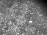
- FIG. 2A is a micrograph of the mixture in Example 1.
- FIG. 2B is a micrograph of the mixture in Example 4.
- FIG. 3 is a schematic diagram of an apparatus for measuring the temperature at occlusion in the examples.
- the sulfide solid electrolyte raw material mixture according to this embodiment is a sulfide solid electrolyte raw material mixture containing Li 2 S and P 2 S 5 , and is characterized in that, when the volume-based average particle size of the Li 2 S measured by a laser diffraction type particle size distribution measurement method is A, and the volume-based average particle size of the P 2 S 5 measured by a laser diffraction type particle size distribution measurement method is B, A ⁇ B is satisfied.
- a mixture of sulfide solid electrolyte raw material containing Li 2 S and P 2 S 5 (hereinafter also referred to as this raw material) (hereinafter also referred to as this mixture) satisfies A ⁇ B, where A is the volume-based average particle size of Li 2 S contained in this mixture measured by a laser diffraction type particle size distribution measurement method, and B is the volume-based average particle size of P 2 S 5 contained in this mixture measured by a laser diffraction type particle size distribution measurement method.
- Li 2 S particles can be brought into contact with the surface of the P 2 S 5 particles in this mixture, or the surface of the P 2 S 5 particles can be covered with Li 2 S particles.
- contact between the P 2 S 5 particles is suppressed, and Li 2 S particles having a relatively high melting point are brought into contact with each other, so that aggregation between the raw material particles can be suppressed, and thus it is considered that clogging of the supply part and the like can be suppressed.
- Li 2 S particles can easily enter the gaps around the P 2 S 5 particles, and many Li 2 S particles can be brought into contact with the surfaces of the P 2 S 5 particles, or the surfaces of the P 2 S 5 particles can be covered with the Li 2 S particles.
- the average particle size of P 2 S 5 larger than the average particle size of Li 2 S, scattering of P 2 S 5 after being charged into a heating furnace can be suppressed, and therefore, the P 2 S 5 can be suppressed from coming into contact with the furnace wall and volatilizing.
- the above A is preferably 0.1 to 50 ⁇ m.
- the above A is preferably 0.1 ⁇ m or more, more preferably 1 ⁇ m or more, and particularly preferably 2 ⁇ m or more.
- the above A is preferably 50 ⁇ m or less, more preferably 40 ⁇ m or less, and particularly preferably 30 ⁇ m or less.
- the above B is preferably 50 ⁇ m or more (B ⁇ 50 ⁇ m), more preferably 75 ⁇ m or more, even more preferably 100 ⁇ m or more, and particularly preferably 150 ⁇ m or more.
- the above B is more preferably 2000 ⁇ m or less, even more preferably 1750 ⁇ m or less, and particularly preferably 1500 ⁇ m or less.
- the above B may be 50 to 2000 ⁇ m.
- the ratio of A to B is preferably 0.5 or less (A/B ⁇ 0.5).
- A/B is more preferably 0.4 or less, and particularly preferably 0.3 or less.
- A/B is more preferably 0.0025 or more, even more preferably 0.005 or more, and particularly preferably 0.0075 or more.
- A/B may be 0.0025 to 0.5.
- the volume-based average particle size of Li 2 S and P 2 S 5 measured by a laser diffraction particle size distribution measurement method can be measured, for example, using MT3000II (manufactured by Microtrac).
- the above average particle size means D50 of the volume-based particle size distribution measured by a laser diffraction particle size distribution measurement method.
- the mixture preferably contains lithium halide ( LiHa ) as described below. That is, the mixture is preferably obtained by mixing Li2S powder, P2S5 powder, and LiHa powder as one of the raw materials contained in the raw material.
- the volume-based average particle size of the LiHa powder measured by a laser diffraction particle size distribution measurement method is preferably 0.1 to 2000 ⁇ m.
- the average particle size is preferably 0.1 ⁇ m or more, more preferably 1 ⁇ m or more, and particularly preferably 2 ⁇ m or more.
- the average particle size is preferably 2000 ⁇ m or less, more preferably 1750 ⁇ m or less, and particularly preferably 1500 ⁇ m or less.
- the raw material as long as it contains the above-mentioned Li 2 S and P 2 S 5 , one or more of various other raw materials can be used, and the sulfide solid electrolyte obtained by using these may also be various sulfide solid electrolytes.
- Each of the raw materials contained in the present raw material may be synthesized or may be commercially available.
- Each raw material may be in powder form, and the present raw material containing each raw material may itself be in powder form.
- each of the raw materials may be subjected to a known pretreatment.
- the manufacturing method according to this embodiment may appropriately include at least one of a process of manufacturing the present raw material and a process of pretreatment of at least some of the raw materials of the present raw material as step 0, which is a process of preparing the present raw material, prior to step S1.
- the sulfide solid electrolyte raw material containing Li 2 S and P 2 S 5 may be appropriately determined depending on the composition of the sulfide solid electrolyte to be obtained.
- One of the raw materials contained in this raw material contains, for example, substances such as an alkali metal element (R) and an elemental sulfur (S).
- the alkali metal element (R) include an elemental lithium (Li), an elemental sodium (Na), and an elemental potassium (K).
- the alkali metal element (R) contains a substance such as an elemental lithium (Li).
- the alkali metal element (R) source an appropriate combination of an alkali metal element, an alkali metal element-containing substance, such as an alkali metal element-containing compound, etc. can be used.
- the alkali metal element (R) is lithium element (Li)
- an appropriate combination of Li-containing substances, such as Li element, Li-containing compound, etc. can be used as the lithium element source.
- the raw material contains at least Li 2 S, which can be a lithium element (Li) source.
- Examples of the substance containing lithium element (Li) include lithium compounds such as lithium iodide (LiI), lithium carbonate ( Li2CO3 ) , lithium sulfate ( Li2SO4 ), lithium oxide ( Li2O ), and lithium hydroxide (LiOH) , as well as metallic lithium, in addition to the above-mentioned lithium sulfide (Li2S).
- LiI lithium iodide
- Li2CO3 lithium carbonate
- Li2SO4 lithium sulfate
- Li2O lithium oxide
- LiOH lithium hydroxide
- LiOH lithium hydroxide
- One type of substance containing lithium element (Li) may be used, or two or more types may be used in combination.
- lithium sulfide As a substance containing lithium element (Li), it is preferable to use lithium sulfide from the viewpoint of obtaining a sulfide material. Furthermore, if the obtained sulfide solid electrolyte contains a halogen element, it is also preferable to use lithium halide (LiHa, where Ha is a halogen element) as a substance containing lithium element (Li). Lithium halide will be described later.
- the sulfur element (S) source a suitable combination of substances containing S, such as simple S or compounds containing S, can be used.
- the substance containing the sulfur element (S) may be used alone or in combination of two or more.
- the raw material contains at least Li 2 S and P 2 S 5 , which can be a source of the sulfur element (S).
- Li 2 S is a compound that serves both as a substance containing the sulfur element (S) and the substance containing the lithium element (Li) described above.
- P 2 S 5 is a compound that serves both as a substance containing the sulfur element (S) and a substance containing the phosphorus element (P) described later.
- Examples of substances containing elemental sulfur (S) include phosphorus pentasulfide (P 2 S 5 ), as well as phosphorus sulfides such as phosphorus trisulfide (P 2 S 3 ), other sulfur compounds containing phosphorus, elemental sulfur, and compounds containing sulfur.
- Examples of compounds containing sulfur include H 2 S, CS 2 , iron sulfide (FeS, Fe 2 S 3 , FeS 2 , Fe 1-x S, etc.), bismuth sulfide (Bi 2 S 3 ), and copper sulfide (CuS, Cu 2 S, Cu 1-x S, etc.).
- the raw material further contains phosphorus (P).
- P phosphorus
- the phosphorus (P) source a suitable combination of substances containing P, such as simple P or a compound containing P, can be used.
- One type of substance containing phosphorus (P) may be used, or two or more types may be used in combination.
- the raw material contains at least P 2 S 5 , which can be a phosphorus (P) source.
- substances containing phosphorus include, in addition to the above-mentioned diphosphorus pentasulfide (P 2 S 5 ), phosphorus sulfides such as diphosphorus trisulfide (P 2 S 3 ), phosphorus compounds such as sodium phosphate (Na 3 PO 4 ), and elemental phosphorus.
- the mixing ratio of the raw materials is not particularly limited.
- the molar ratio S/R of sulfur element (S) to alkali metal element (R) in the mixture is preferably 0.65/0.35 or less, and more preferably 0.5/0.5 or less, from the viewpoint of improving the ionic conductivity of the resulting sulfide solid electrolyte.
- the mixture is preferably obtained by mixing the raw materials in a predetermined stoichiometric ratio.
- the method of mixing the raw materials to obtain the mixture is not particularly limited, but examples include mixing in a mortar, mixing using media such as a planetary ball mill, media-less mixing such as a pin mill, a powder mixer, or airflow mixing.
- combinations of substances containing an alkali metal element and substances containing a sulfur element include a combination of Li 2 S and P 2 S 5 , and in the case where the resulting sulfide solid electrolyte has a halogen element as a constituent element, a combination of Li 2 S, P 2 S 5 , and LiHa, etc. can be mentioned.
- the molar ratio Li/P of Li to P is preferably 40/60 to 88/12, more preferably 50/50 to 88/12.
- the raw material is a substance containing Li, such as metallic lithium, lithium halide (LiHa), lithium carbonate ( Li2CO3 ), lithium sulfate ( Li2SO4 ), lithium oxide ( Li2O ), lithium hydroxide ( LiOH ), etc. These may be used alone or in combination of two or more.
- the raw material may contain further substances (compounds, etc.) in addition to the above substances depending on the composition of the desired sulfide solid electrolyte or as additives, etc.
- the raw material when producing a sulfide solid electrolyte containing a halogen element such as F, Cl, Br or I, the raw material preferably contains a halogen element (Ha).
- the raw material when producing a sulfide solid electrolyte containing a halogen element such as F, Cl, Br or I, the raw material preferably contains a halogen element (Ha).
- the raw material preferably contains a compound containing a halogen element.
- Examples of compounds containing halogen elements include lithium halides such as lithium fluoride (LiF), lithium chloride (LiCl), lithium bromide (LiBr), and lithium iodide (LiI), phosphorus halides, phosphoryl halides, sulfur halides, sodium halides, and boron halides.
- lithium halides such as lithium fluoride (LiF), lithium chloride (LiCl), lithium bromide (LiBr), and lithium iodide (LiI), phosphorus halides, phosphoryl halides, sulfur halides, sodium halides, and boron halides.
- lithium halides are preferred, LiCl, LiBr, and LiI are more preferred, and LiCl and LiBr are even more preferred. These compounds may be used alone or in combination of two or more.
- alkali metal halides such as lithium halide are also compounds containing alkali metal elements such as Li, they can also be a source of the alkali metal element (R) in this raw material.
- the molar equivalent of the halogen element (Ha) relative to the phosphorus element (P) in the mixture is preferably 0.2 to 4 molar equivalents, more preferably 0.5 to 3 molar equivalents.
- the molar equivalent of the halogen element is preferably 0.2 molar equivalents or more, more preferably 0.5 molar equivalents or more.
- the molar equivalent of the halogen element is preferably 4 molar equivalents or less, more preferably 3 molar equivalents or less. Note that, when the powder raw material contains two or more types of halogen elements, it is preferable that the total content thereof satisfies the above molar equivalent range.
- the raw material preferably contains sulfides such as SiS 2 , B 2 S 3 , GeS 2 , and Al 2 S 3 from the viewpoint of easily forming the amorphous phase and reducing the load on the equipment even if the quenching rate is reduced. These may be used alone or in combination of two or more.
- the raw material preferably contains oxides such as SiO 2 , B 2 O 3 , GeO 2 , Al 2 O 3 , and P 2 O 5. These may be used alone or in combination of two or more.
- the content of the sulfides and oxides is preferably 0.1 to 50 mass% and more preferably 0.5 to 40 mass% based on the total amount of the raw material.
- the content is preferably 0.1 mass% or more and more preferably 0.5 mass% or more, and is preferably 50 mass% or less and more preferably 40 mass% or less.
- the mixture may further contain a compound that will serve as a crystal nucleus, as described below.
- the present embodiment aims to suppress clogging caused by the fact that the melting point of P 2 S 5 is low and particles tend to adhere to each other even at low temperatures, but also has a suppression effect on clogging caused by compounds with low melting points other than P 2 S 5.
- compounds with low melting points other than P 2 S 5 include LiI, B 2 S 3 , S, Se, and Sb 2 S 3. Therefore, the present mixture is also effective in producing a sulfide solid electrolyte using the present raw material containing the above-mentioned compounds with low melting points together with P 2 S 5 .
- the manufacturing method is a method for manufacturing a sulfide solid electrolyte, comprising: charging a sulfide solid electrolyte raw material into a heated furnace body and mixing to obtain a mixture of the sulfide solid electrolyte raw materials; or charging a mixture of the sulfide solid electrolyte raw materials into a heated furnace body, heating and melting the mixture of the sulfide solid electrolyte raw materials, and cooling and solidifying the resulting molten liquid to obtain a sulfide solid electrolyte, wherein the mixture of the sulfide solid electrolyte raw materials contains Li 2 S and P 2 S 5 , and where A is a volume-based average particle size of the Li 2 S measured by a laser diffraction particle size distribution measurement method and B is a volume-based average particle size of the P 2 S 5 measured by a laser diffraction particle size distribution
- the manufacturing method according to this embodiment includes the following steps.
- Step S1 A step of charging a sulfide solid electrolyte raw material into a heated furnace body and mixing to obtain a mixture of the sulfide solid electrolyte raw material, or a step of charging a mixture of the sulfide solid electrolyte raw material into a heated furnace body
- Step S2 A step of heating and melting the mixture of the sulfide solid electrolyte raw material, and cooling and solidifying the resulting melt to obtain a sulfide solid electrolyte.
- Step S1 A step of introducing a sulfide solid electrolyte raw material into a heated furnace body and mixing the sulfide solid electrolyte raw material to obtain a mixture of the sulfide solid electrolyte raw material, or a step of introducing a mixture of the sulfide solid electrolyte raw material into a heated furnace body>
- the sulfide solid electrolyte raw material or the mixture of sulfide solid electrolyte raw materials is charged into a heated furnace body.
- charging the sulfide solid electrolyte raw material or the mixture of sulfide solid electrolyte raw materials into a heated furnace body may mean starting the charging of the sulfide solid electrolyte raw material or the mixture of sulfide solid electrolyte raw materials while the furnace body is heated, or starting heating of the furnace body during the charging of the sulfide solid electrolyte raw material or the mixture of sulfide solid electrolyte raw materials.
- the temperature of the heated furnace body is preferably, for example, 500 to 1000°C.
- the temperature of the heated furnace body is preferably 500°C or higher, more preferably 550°C or higher, and particularly preferably 600°C or higher, and is preferably 1000°C or lower, more preferably 950°C or lower, and particularly preferably 900°C or lower.
- the furnace body in the heating furnace used for heating and melting can be any conventional furnace with a heating section, and the material and size of the furnace body can be selected as desired.
- the sulfide solid electrolyte raw material may be charged into the heated furnace body and mixed to obtain a mixture of sulfide solid electrolyte raw materials, or the mixture of sulfide solid electrolyte raw materials may be charged into the heated furnace body.
- the mixture of the sulfide solid electrolyte raw material and the sulfide solid electrolyte raw material means the mixture of the sulfide solid electrolyte raw material and the sulfide solid electrolyte raw material described above in "Mixture of sulfide solid electrolyte raw materials".
- the charging ratio of the raw materials may be determined appropriately depending on, for example, the composition of the desired sulfide solid electrolyte.
- the mixing ratio of the raw materials may be determined appropriately depending on, for example, the composition of the desired sulfide solid electrolyte.
- Step S2 Heat and melt the mixture of sulfide solid electrolyte raw materials, and cool and solidify the resulting melt to obtain a sulfide solid electrolyte ⁇
- step S2 in this embodiment the raw materials or the mixture are charged into a heating furnace, the raw materials are mixed as necessary to obtain the mixture, and then the mixture is heated and melted.
- the temperature of the heat melting is not particularly limited as long as the mixture melts, but is preferably 600° C. or higher, more preferably 600 to 1000° C., even more preferably 630 to 950° C., even more preferably 650° C. or higher and lower than 900° C., and particularly preferably 650° C. or higher and lower than 850° C.
- the heat melting temperature is preferably 600° C. or higher, more preferably 630° C. or higher, and even more preferably 650° C. or higher.
- the heat melting temperature is preferably 1000° C. or lower, more preferably 950° C. or lower, even more preferably lower than 900° C., and particularly preferably lower than 850° C.
- the heating and melting temperature is the temperature of the molten liquid produced in the furnace, and can be adjusted by a heating unit provided in the furnace.
- the heating and melting time is not particularly limited as long as the mixture is melted, but may be, for example, 0.5 hours or more, 1 hour or more, or 2 hours or more.
- the pressure during heating and melting is not particularly limited as long as the mixture melts, but normal pressure or slight pressure is preferable, and normal pressure is more preferable.
- the dew point inside the furnace is preferably -20°C or lower, and although there is no particular lower limit for the dew point, it is usually -80°C or higher.
- the oxygen concentration inside the furnace is preferably 1000 ppm by volume or less.
- the heating and melting is preferably carried out in a gas atmosphere containing elemental sulfur.
- a gas atmosphere containing elemental sulfur By heating and melting the mixture in a gas atmosphere containing elemental sulfur, sulfur is introduced into the resulting molten liquid, and changes in the sulfur composition due to volatilization can be suppressed.
- gases containing elemental sulfur include sulfur gas, hydrogen sulfide gas, carbon disulfide gas, and other compounds containing elemental sulfur or gases containing elemental sulfur.
- the gas atmosphere containing the elemental sulfur may be obtained by supplying a sulfur source into a melt obtained by heating and melting the mixture, and then heating the sulfur source to generate a gas containing the elemental sulfur.
- the sulfur source is not particularly limited as long as it is elemental sulfur or a sulfur compound that can produce a gas containing elemental sulfur by heating, and examples of the sulfur source include elemental sulfur, hydrogen sulfide, organic sulfur compounds such as carbon disulfide, iron sulfide (FeS, Fe 2 S 3 , FeS 2 , Fe 1-x S, etc.), bismuth sulfide (Bi 2 S 3 ), copper sulfide (CuS, Cu 2 S, Cu 1-x S, etc.), polysulfides such as lithium polysulfide and sodium polysulfide, polysulfides, and rubber that has been subjected to sulfur vulcanization treatment.
- sulfur powder is preferably used as the sulfur powder.
- the gas atmosphere containing elemental sulfur may be obtained by introducing previously obtained sulfur vapor into the furnace body.
- sulfur is heated at 200 to 450° C. to generate sulfur vapor, and the sulfur vapor is transported into the furnace body using an inert gas such as N 2 gas, argon gas, or helium gas as a carrier gas, to obtain a gas atmosphere containing elemental sulfur.
- an inert gas such as N 2 gas, argon gas, or helium gas as a carrier gas
- the gas atmosphere containing elemental sulfur may be obtained by incorporating a sulfur source in the mixture.
- the sulfur source is also heated, so that the raw material can be heated and melted in a gas atmosphere containing the generated elemental sulfur.
- the method for obtaining the gas atmosphere containing elemental sulfur described above may be any one of the methods or a combination of multiple methods.
- Cooling and solidification The melt obtained by the above heating and melting is cooled and solidified to obtain a sulfide solid electrolyte. By cooling the melt, a solid sulfide solid electrolyte is obtained.
- the molten liquid obtained by the above heating and melting is discharged at any time from an outlet provided in the furnace body, and the process proceeds to cooling and solidifying.
- the molten liquid can be cooled by any known method, and is not particularly limited.
- cooling using twin rollers which is generally considered to have the fastest quenching speed, is preferred.
- the cooling rate is preferably 0.01°C/sec or more, more preferably 0.05°C/sec or more, and even more preferably 0.1°C/sec or more.
- the cooling rate of the twin rollers is, for example, 1,000,000°C/sec or less.
- the cooling rate during quenching is preferably 10°C/sec or more, more preferably 100°C/sec or more, even more preferably 500°C/sec or more, and particularly preferably 700°C/sec or more.
- the upper limit of the cooling rate during quenching is not particularly limited, but the cooling rate of the twin rollers is, for example, 1,000,000°C/sec or less.
- a sulfide solid electrolyte having a crystalline phase may be obtained by slowly cooling during the cooling and solidifying step, or a sulfide solid electrolyte having a crystalline phase and an amorphous phase may be obtained.
- the cooling rate is preferably 0.01 to 500° C./sec, more preferably 0.05 to 450° C./sec, and may also be 0.01 to 10° C./sec, or 0.05 to 5° C./sec.
- the cooling rate is preferably 0.01° C./sec or more, more preferably 0.05° C./sec or more, and is preferably 500° C./sec or less, more preferably 450° C./sec or less.
- the cooling rate may be 10° C./sec or less, or 5° C./sec or less.
- the cooling rate may be adjusted appropriately depending on the crystallization conditions.
- the crystal of the sulfide solid electrolyte is preferably an ion-conductive crystal.
- the ion-conductive crystal is preferably a crystal having a lithium ion conductivity of more than 1.0 ⁇ 10 ⁇ 4 S/cm, and more preferably a crystal having a lithium ion conductivity of more than 1.0 ⁇ 10 ⁇ 3 S/cm.
- a compound that will become a crystal nucleus is added to the melt in order to facilitate crystal precipitation.
- the method of adding a compound that will become a crystal nucleus to the melt is not particularly limited, but examples thereof include a method of adding a compound that will become a crystal nucleus to the mixture in step S1, and a method of directly adding the compound that will become a crystal nucleus to the melt that is being heated and melted.
- Compounds that can become crystal nuclei include oxides, oxynitrides, nitrides, carbides, other chalcogen compounds, halides, etc.
- Compounds that can become crystal nuclei are preferably compounds that have a certain degree of compatibility with the melt. Compounds that are completely incompatible with the melt cannot become crystal nuclei.
- the amount of the compound that will become the crystal nuclei added to the melt is preferably 0.01 to 20 mass%, more preferably 0.1 to 20 mass%, and even more preferably 1 to 10 mass%.
- the amount added is preferably 0.01 mass% or more, more preferably 0.1 mass% or more, and even more preferably 1 mass% or more.
- the amount added is preferably 20 mass% or less, and more preferably 10 mass% or less.
- the amount added is preferably 1 mass% or less, and more preferably 0.1 mass% or less. The amount added may also be 0.01 mass% or less.
- the cooling and solidification is preferably carried out under normal pressure.
- Under normal pressure means that the pressure is not controlled during cooling. Specifically, it is about 0.8 to 1.2 atm.
- the sulfide solid electrolyte obtained in step S2 may be heated again to perform a heat treatment.
- the heat treatment may be particularly performed.
- the heat treatment may also rearrange the ions within the crystal structure to increase lithium ion conductivity.
- the above-mentioned heat treatment refers to at least one of a heat treatment for crystallizing the obtained solid and a heat treatment for rearranging ions in the crystal structure.
- the above-mentioned heat treatment also includes a crystallization treatment by heating an amorphous sulfide solid electrolyte or a sulfide solid electrolyte containing an amorphous phase.
- the manufacturing method according to this embodiment it is preferable to carry out the above steps S1 and S2 as a continuous process. That is, it is preferable to continuously feed the raw materials or the mixture into the furnace body, mix the raw materials as necessary to obtain the mixture, heat and melt it, and continuously discharge the resulting molten liquid, and move to a process of cooling and solidifying it, thereby continuously obtaining a sulfide solid electrolyte. In this way, it is preferable to continuously manufacture the sulfide solid electrolyte.
- the mixture is first heated and melted in an amount sufficient to form at least a melt surface in the furnace.
- the melt surface means a liquid surface formed by the melt covering the entire bottom surface of the furnace.
- Such continuous production of the sulfide solid electrolyte allows a large amount of the sulfide solid electrolyte to be produced in a short period of time. Furthermore, the shortening of the production process also reduces the volatilization of the raw materials during the production process.
- the processes of steps S1 and S2 may be carried out in a batch manner.
- the batch manner refers to a method in which the sulfide solid electrolyte raw material or a mixture thereof is charged into the furnace body, and then heated and melted, and the entire amount is discharged, and refers to a method in which the contents of the furnace body are all replaced each time the manufacturing method according to this embodiment is carried out.
- the sulfide solid electrolyte obtained by the manufacturing method according to the present embodiment includes a sulfide solid electrolyte having elements of Li, P, and S, and for example, a sulfide solid electrolyte having an LGPS type crystal structure such as Li 10 GeP 2 S 12. and sulfide solid electrolytes having an argyrodite-type crystal structure, such as Li 6 PS 5 Cl, Li 5.4 PS 4.4 Cl 1.6 , and Li 5.4 PS 4.4 Cl 0.8 Br 0.8.
- the glass-ceramics include electrolytes, Li-PS-Ha-based (Ha represents at least one element selected from halogen elements) crystallized glasses, and LPS crystallized glasses such as Li 7 P 3 S 11 .
- the sulfide solid electrolyte may be an amorphous sulfide solid electrolyte, a sulfide solid electrolyte having a specific crystal structure, or a sulfide solid electrolyte containing a crystalline phase and an amorphous phase.
- the crystalline phase is more preferably an argyrodite-type crystalline phase.
- a sulfide solid electrolyte having the elements Li, P, S, and Ha is preferred, and it is more preferred that it has a crystalline phase.
- the Ha element is derived from one or more elements selected from the group consisting of lithium chloride, lithium bromide, and lithium iodide.
- the lithium ion conductivity of the sulfide solid electrolyte is preferably 1.0 ⁇ 10 ⁇ 4 S/cm or more, more preferably 5.0 ⁇ 10 ⁇ 4 S/cm or more, even more preferably 1.0 ⁇ 10 ⁇ 3 S/cm or more, and particularly preferably 5.0 ⁇ 10 ⁇ 3 S/cm or more, from the viewpoint of battery characteristics when used in a lithium ion secondary battery.
- the lithium ion conductivity in this specification is a value measured using an AC impedance measuring device (for example, Potentiostat/Galvanostat VSP manufactured by Bio-Logic Sciences Instruments) under the conditions of a measurement frequency of 100 Hz to 1 MHz, a measurement voltage of 100 mV, and a measurement temperature of 25° C.
- an AC impedance measuring device for example, Potentiostat/Galvanostat VSP manufactured by Bio-Logic Sciences Instruments
- the obtained sulfide solid electrolyte can be identified by analyzing the crystal structure using X-ray diffraction (XRD) measurement, and by analyzing the elemental composition using various methods such as ICP optical emission spectrometry, atomic absorption spectrometry, and ion chromatography.
- ICP optical emission spectrometry atomic absorption spectrometry
- ion chromatography ion chromatography
- the present invention is not limited to the above-described embodiments, and various modifications can be made within the scope of the present invention.
- the present invention is not limited to the above-described embodiments, and modifications and improvements can be made as appropriate.
- the material, shape, dimensions, number, and location of each component in the above-described embodiments are arbitrary and not limited as long as they can achieve the present invention.
- a mixture of sulfide solid electrolyte raw materials containing Li 2 S and P 2 S 5 wherein A is a volume-based average particle size of the Li 2 S measured by a laser diffraction type particle size distribution measurement method, and B is a volume-based average particle size of the P 2 S 5 measured by a laser diffraction type particle size distribution measurement method, and the mixture of sulfide solid electrolyte raw materials satisfies A ⁇ B.
- the mixture of sulfide solid electrolyte raw materials contains Li2S and P2S5 , and when the volume-based average particle size of the Li2S measured by a laser diffraction particle size distribution measurement method is A and the volume-based average particle size of the P2S5 measured by a laser diffraction particle size distribution measurement method is B
- the method for producing a sulfide solid electrolyte according to any one of 4 to 7 above further comprising heating and melting the mixture of raw materials for the sulfide solid electrolyte to obtain a melt, and then supplying a sulfur source into the melt.
- 9. The method for producing a sulfide solid electrolyte according to any one of 4 to 8 above, wherein a sulfur source is added to the mixture of raw materials for the sulfide solid electrolyte, and then the mixture is heated and melted.
- Examples 1 and 2 are examples, and Examples 3 and 4 are comparative examples.
- Example 1 ( Li2S Crushing) First, in order to reduce the diameter of Li 2 S, the Li 2 S raw material was pulverized at a rotation speed of 24000 rpm for 300 sec using MX1100XTM manufactured by WARING Co., Ltd. The pulverized Li 2 S was measured using a laser diffraction particle size distribution measurement method using MT3000II manufactured by Microtrack Co., Ltd., with dibutyl ether as a measurement solvent, a particle refractive index of 1.81, and a solvent refractive index of 1.353, and the D50 of the volume-based particle size distribution was measured to be 12 ⁇ m.
- Example 2 The Li 2 S raw material was passed through a 100 ⁇ m mesh sieve, dibutyl ether was used as the measurement solvent, the particle refractive index was 1.81, the solvent refractive index was 1.353, and the Li 2 S raw material had a volume-based particle size distribution D50 of 70 ⁇ m measured by a laser diffraction particle size distribution measurement method using a Microtrack MT3000II, and a mixture of sulfide solid electrolyte raw materials for Example 2 was obtained in the same manner as in Example 1, except that a Li 2 S raw material was used having a particle refractive index of 1.81, a solvent refractive index of 1.353, and a volume-based particle size distribution D50 of 70 ⁇ m measured by a laser diffraction particle size distribution measurement method using a Microtrack MT3000II.
- Example 3 A mixture of sulfide solid electrolyte raw materials of Example 3 was obtained in the same manner as in Example 1, except that dibutyl ether was used as a measurement solvent, the particle refractive index was 1.81, the solvent refractive index was 1.353, and Li 2 S raw material having a volume-based particle size distribution D50 of 720 ⁇ m measured by a laser diffraction particle size distribution measurement method using MT3000II manufactured by Microtrack was used.
- Example 4 The Li 2 S raw material and the P 2 S 5 raw material were passed through a 500 ⁇ m mesh sieve, dibutyl ether was used as the measurement solvent, the particle refractive index was 1.81, the solvent refractive index was 1.353, and the volume-based particle size distribution D50 measured by a laser diffraction particle size distribution measurement method using a Microtrack MT3000II was 365 ⁇ m and 150 ⁇ m, respectively.
- the sulfide solid electrolyte of Example 4 was obtained in the same manner as in Example 1, except that Li 2 S raw materials were used having a particle refractive index of 1.81, a solvent refractive index of 1.353, and a volume-based particle size distribution D50 of 365 ⁇ m and 150 ⁇ m, respectively.
- Table 1 shows the temperature and other data at the time of blockage for each example.
- Li 2 S particles can be brought into contact with the surface of the P 2 S 5 particles in this mixture, or the surface of the P 2 S 5 particles can be covered with Li 2 S particles, so that the contact between the P 2 S 5 particles is suppressed and the Li 2 S particles having a relatively high melting point come into contact with each other, so that aggregation between the raw material particles can be suppressed, and thus clogging of the supply section and the like can be suppressed.
- the D50 of Li 2 S in the mixture of raw material powders was larger than the D50 of P 2 S 5 , so the temperature at the time of clogging was low. This indicates that the aggregation clogging caused by the raw material cannot be sufficiently suppressed.
- the particle size of the Li 2 S particles is large, so that the Li 2 S particles cannot be sufficiently contacted with the surface of the P 2 S 5 particles in this mixture, or the surface of the P 2 S 5 particles cannot be covered with the Li 2 S particles, so it is considered that the aggregation between the raw material particles cannot be sufficiently suppressed.
Landscapes
- Chemical & Material Sciences (AREA)
- Manufacturing & Machinery (AREA)
- Organic Chemistry (AREA)
- Engineering & Computer Science (AREA)
- Inorganic Chemistry (AREA)
- Condensed Matter Physics & Semiconductors (AREA)
- General Physics & Mathematics (AREA)
- Chemical Kinetics & Catalysis (AREA)
- Electrochemistry (AREA)
- General Chemical & Material Sciences (AREA)
- Physics & Mathematics (AREA)
- Secondary Cells (AREA)
- Conductive Materials (AREA)
Priority Applications (2)
| Application Number | Priority Date | Filing Date | Title |
|---|---|---|---|
| JP2025535720A JPWO2025023039A1 (https=) | 2023-07-21 | 2024-07-11 | |
| CN202480048132.3A CN121548864A (zh) | 2023-07-21 | 2024-07-11 | 硫化物固体电解质原料的混合物和硫化物固体电解质的制造方法 |
Applications Claiming Priority (2)
| Application Number | Priority Date | Filing Date | Title |
|---|---|---|---|
| JP2023-119362 | 2023-07-21 | ||
| JP2023119362 | 2023-07-21 |
Publications (1)
| Publication Number | Publication Date |
|---|---|
| WO2025023039A1 true WO2025023039A1 (ja) | 2025-01-30 |
Family
ID=94375273
Family Applications (1)
| Application Number | Title | Priority Date | Filing Date |
|---|---|---|---|
| PCT/JP2024/025074 Pending WO2025023039A1 (ja) | 2023-07-21 | 2024-07-11 | 硫化物固体電解質原料の混合物および硫化物固体電解質の製造方法 |
Country Status (3)
| Country | Link |
|---|---|
| JP (1) | JPWO2025023039A1 (https=) |
| CN (1) | CN121548864A (https=) |
| WO (1) | WO2025023039A1 (https=) |
Citations (3)
| Publication number | Priority date | Publication date | Assignee | Title |
|---|---|---|---|---|
| JP2014127387A (ja) * | 2012-12-27 | 2014-07-07 | Toyota Motor Corp | 硫化物固体電解質材料の製造方法およびリチウム固体電池 |
| JP2015002053A (ja) * | 2013-06-14 | 2015-01-05 | 出光興産株式会社 | 固体電解質組成物 |
| WO2022025268A1 (ja) * | 2020-07-31 | 2022-02-03 | Agc株式会社 | 硫化物系固体電解質の製造方法及び硫化物系固体電解質 |
-
2024
- 2024-07-11 WO PCT/JP2024/025074 patent/WO2025023039A1/ja active Pending
- 2024-07-11 CN CN202480048132.3A patent/CN121548864A/zh active Pending
- 2024-07-11 JP JP2025535720A patent/JPWO2025023039A1/ja active Pending
Patent Citations (3)
| Publication number | Priority date | Publication date | Assignee | Title |
|---|---|---|---|---|
| JP2014127387A (ja) * | 2012-12-27 | 2014-07-07 | Toyota Motor Corp | 硫化物固体電解質材料の製造方法およびリチウム固体電池 |
| JP2015002053A (ja) * | 2013-06-14 | 2015-01-05 | 出光興産株式会社 | 固体電解質組成物 |
| WO2022025268A1 (ja) * | 2020-07-31 | 2022-02-03 | Agc株式会社 | 硫化物系固体電解質の製造方法及び硫化物系固体電解質 |
Also Published As
| Publication number | Publication date |
|---|---|
| JPWO2025023039A1 (https=) | 2025-01-30 |
| CN121548864A (zh) | 2026-02-17 |
Similar Documents
| Publication | Publication Date | Title |
|---|---|---|
| JP7782592B2 (ja) | 硫化物系固体電解質の製造方法及び硫化物系固体電解質 | |
| CN116438140A (zh) | 硫化物系固体电解质、固体电解质层和锂离子二次电池 | |
| US20250149628A1 (en) | Sulfide solid electrolyte, and method for producing same | |
| US20250070238A1 (en) | Method and apparatus for producing sulfide solid electrolyte | |
| JP7677479B2 (ja) | アルカリ金属元素及び硫黄元素を含む物質の製造方法 | |
| JP7537654B1 (ja) | 硫化物固体電解質の製造方法 | |
| WO2025023039A1 (ja) | 硫化物固体電解質原料の混合物および硫化物固体電解質の製造方法 | |
| JP7416173B1 (ja) | 硫化物系固体電解質の製造方法および硫化物系固体電解質の製造装置 | |
| WO2025023042A1 (ja) | 硫化物固体電解質の製造方法 | |
| WO2025023041A1 (ja) | 硫化物固体電解質の製造方法 | |
| WO2025023037A1 (ja) | 硫化物固体電解質の製造方法 | |
| JP7440002B1 (ja) | 硫化物系固体電解質の製造方法及び製造装置 | |
| WO2025126948A1 (ja) | 硫化物固体電解質の製造方法および硫化物固体電解質 | |
| WO2025023035A1 (ja) | 硫化物固体電解質の製造方法 | |
| US20260112692A1 (en) | Method for producing sulfide solid electrolyte and method for reusing same | |
| US20250372703A1 (en) | Method for producing sulfide solid electrolyte composite, sulfide solid electrolyte composite, and method for producing composite powder | |
| WO2025220607A1 (ja) | 硫化物固体電解質の製造方法、及び硫化物固体電解質の製造装置 | |
| WO2025121293A1 (ja) | 硫化物固体電解質及びその製造方法 | |
| WO2025121290A1 (ja) | 硫化物固体電解質及びその製造方法 | |
| WO2025197831A1 (ja) | 硫化物固体電解質及びリチウムイオン二次電池の製造方法、並びに、硫化物固体電解質 | |
| WO2024095938A1 (ja) | 硫化物系固体電解質の製造方法および硫化物系固体電解質の製造装置 | |
| WO2024157974A1 (ja) | 硫化物固体電解質粉末の製造方法 |
Legal Events
| Date | Code | Title | Description |
|---|---|---|---|
| 121 | Ep: the epo has been informed by wipo that ep was designated in this application |
Ref document number: 24845420 Country of ref document: EP Kind code of ref document: A1 |
|
| ENP | Entry into the national phase |
Ref document number: 2025535720 Country of ref document: JP Kind code of ref document: A |
|
| WWE | Wipo information: entry into national phase |
Ref document number: 2025535720 Country of ref document: JP |
|
| NENP | Non-entry into the national phase |
Ref country code: DE |