WO2025022640A1 - 全固体電池用電解質複合体及び全固体電池 - Google Patents
全固体電池用電解質複合体及び全固体電池 Download PDFInfo
- Publication number
- WO2025022640A1 WO2025022640A1 PCT/JP2023/027554 JP2023027554W WO2025022640A1 WO 2025022640 A1 WO2025022640 A1 WO 2025022640A1 JP 2023027554 W JP2023027554 W JP 2023027554W WO 2025022640 A1 WO2025022640 A1 WO 2025022640A1
- Authority
- WO
- WIPO (PCT)
- Prior art keywords
- electrolyte
- solid
- insulating frame
- porous body
- state battery
- Prior art date
- Legal status (The legal status is an assumption and is not a legal conclusion. Google has not performed a legal analysis and makes no representation as to the accuracy of the status listed.)
- Pending
Links
Images


Classifications
-
- H—ELECTRICITY
- H01—ELECTRIC ELEMENTS
- H01M—PROCESSES OR MEANS, e.g. BATTERIES, FOR THE DIRECT CONVERSION OF CHEMICAL ENERGY INTO ELECTRICAL ENERGY
- H01M10/00—Secondary cells; Manufacture thereof
- H01M10/05—Accumulators with non-aqueous electrolyte
- H01M10/056—Accumulators with non-aqueous electrolyte characterised by the materials used as electrolytes, e.g. mixed inorganic/organic electrolytes
- H01M10/0561—Accumulators with non-aqueous electrolyte characterised by the materials used as electrolytes, e.g. mixed inorganic/organic electrolytes the electrolyte being constituted of inorganic materials only
- H01M10/0562—Solid materials
-
- H—ELECTRICITY
- H01—ELECTRIC ELEMENTS
- H01M—PROCESSES OR MEANS, e.g. BATTERIES, FOR THE DIRECT CONVERSION OF CHEMICAL ENERGY INTO ELECTRICAL ENERGY
- H01M10/00—Secondary cells; Manufacture thereof
- H01M10/05—Accumulators with non-aqueous electrolyte
- H01M10/058—Construction or manufacture
-
- Y—GENERAL TAGGING OF NEW TECHNOLOGICAL DEVELOPMENTS; GENERAL TAGGING OF CROSS-SECTIONAL TECHNOLOGIES SPANNING OVER SEVERAL SECTIONS OF THE IPC; TECHNICAL SUBJECTS COVERED BY FORMER USPC CROSS-REFERENCE ART COLLECTIONS [XRACs] AND DIGESTS
- Y02—TECHNOLOGIES OR APPLICATIONS FOR MITIGATION OR ADAPTATION AGAINST CLIMATE CHANGE
- Y02E—REDUCTION OF GREENHOUSE GAS [GHG] EMISSIONS, RELATED TO ENERGY GENERATION, TRANSMISSION OR DISTRIBUTION
- Y02E60/00—Enabling technologies; Technologies with a potential or indirect contribution to GHG emissions mitigation
- Y02E60/10—Energy storage using batteries
Definitions
- the present invention relates to an electrolyte composite for an all-solid-state battery and an all-solid-state battery.
- All-solid-state batteries that use solid electrolytes are known.
- One such all-solid-state battery is known to have a configuration in which the solid electrolyte is supported by a porous body. If the solid electrolyte is supported by a porous body, it becomes possible to impart self-supporting properties to the electrolyte layer, and it becomes possible to handle the electrolyte layer independently.
- Patent Document 1 JP 2019-192564 A discloses an all-solid-state battery including a laminated electrode body having a laminated structure with a specific positive electrode, a specific negative electrode, and a separator layer including a porous substrate and solid electrolyte particles held by the substrate.
- the separator layer has a protruding portion that protrudes outward beyond the end of the opposing portion of the positive electrode and negative electrode, and that at least a portion of the protruding portion is formed by a dense structure portion.
- Patent Document 1 also describes that the dense structure portion prevents defects associated with the falling off of solid electrolyte particles.
- the object of the present invention is therefore to provide a technology that can prevent damage to the ends of an electrolyte layer in an all-solid-state battery that uses a porous body for the electrolyte layer.
- the present invention relates to an electrolyte composite for an all-solid-state battery.
- This electrolyte composite for an all-solid-state battery comprises a porous body having an electrolyte region that supports a solid electrolyte, and an insulating frame that is disposed so as to surround the porous body and is joined to the outer periphery of the porous body.
- the insulating frame is ionically and electronically insulating, and is formed of a separate member from the porous body.
- the present invention relates to an all-solid-state battery.
- This all-solid-state battery includes the above-mentioned electrolyte composite, and a positive electrode active material layer and a negative electrode active material layer arranged to sandwich the electrolyte-filled region in the thickness direction.
- FIG. 1 is a schematic cross-sectional view showing an all-solid-state battery according to a first embodiment.
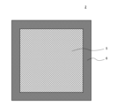
- FIG. 2 is a plan view showing the electrolyte complex.
- FIG. 3 is a diagram for explaining the thickness of the insulating frame.
- FIG. 4 is a schematic cross-sectional view showing a modification of the first embodiment.
- FIG. 5 is a schematic cross-sectional view showing another modified example of the first embodiment.
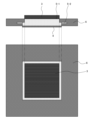
- FIG. 6 is a schematic diagram showing an all-solid-state battery according to the second embodiment.
- all-solid-state battery refers to a secondary battery in which the electrolyte layer, the positive electrode active material layer, and the negative electrode active material layer are all substantially solid. Each layer may be “substantially” solid, and a small amount of liquid material may be used.
- FIG. 1 is a schematic cross-sectional view showing an all-solid-state battery 1 according to a first embodiment.
- the all-solid-state battery 1 has an electrolyte complex 2, a positive electrode active material layer 3, and a negative electrode active material layer 4. These are stacked in the stacking direction. Specifically, the electrolyte complex 2 is sandwiched between the positive electrode active material layer 3 and the negative electrode active material layer 4. Although not shown, a current collector and the like are further disposed on the outside of the positive electrode active material layer 3 and the negative electrode active material layer 4.
- charging and discharging are performed by the conduction of lithium ions between the positive electrode active material layer 3 and the negative electrode active material layer 4. That is, during charging, lithium ions are conducted from the positive electrode active material layer 3 to the negative electrode active material layer 4 via the electrolyte complex 2. On the other hand, during discharging, lithium ions are conducted from the negative electrode active material layer 4 to the positive electrode active material layer 3 via the electrolyte complex 2.
- the electrolyte composite 2 has a porous body 5 and an insulating frame 6.
- the porous body 5 is in a sheet shape and is provided to support the solid electrolyte. That is, the porous body 5 is provided with an electrolyte region 5-1, which is a region in which the solid electrolyte is supported. In the electrolyte region 5-1, the pores of the porous body 5 are filled with the solid electrolyte.
- the electrolyte region 5-1 is sandwiched between the positive electrode active material layer 3 and the negative electrode active material layer 4 in the stacking direction.
- the electrolyte region 5-1 is a portion that functions as an electrolyte layer in the all-solid-state battery 1. During charging and discharging, lithium ions move between the positive electrode active material layer 3 and the negative electrode active material layer 4 through the electrolyte region 5-1.
- the porous body 5 is provided with a non-electrolyte region 5-2.
- the non-electrolyte region 5-2 is a region lacking a solid electrolyte.
- the non-electrolyte region 5-2 is provided on the outer periphery of the porous body 5 and surrounds the electrolyte region 5-1. When viewed along the stacking direction, the non-electrolyte region 5-2 is located outside the electrode layers (positive electrode active material layer 3 and negative electrode active material layer 4).
- FIG. 2 is a plan view showing the electrolyte complex 2.
- the insulating frame 6 is arranged so as to surround the porous body 5.
- the insulating frame 6 is joined to the outer periphery of the porous body 5.
- the insulating frame 6 is joined to the non-electrolyte region 5-2 of the porous body 5.
- the insulating frame 6 sandwiches the non-electrolyte region 5-2 at its inner end from both sides in the stacking direction.
- the insulating frame 6 is ionically and electronically insulating.
- the insulating frame 6 is formed from a separate member from the porous body 5.
- the insulating frame 6 is dense.
- the above is a schematic configuration of the all-solid-state battery 1 according to this embodiment.
- an insulating frame 6, which is a separate member from the porous body 5, is joined to the outer periphery of the porous body 5. Therefore, it is possible to adopt a configuration for the insulating frame 6 that has high strength that cannot be realized by the porous body 5, for example. This makes it possible to increase the strength at the ends of the electrolyte complex 2. Therefore, even if the thickness of the porous body 5 is thin, it is possible to prevent damage to the ends and prevent short circuits at the ends. In addition, since the ends are less likely to be damaged, the electrolyte complex 2 is easy to handle during production. In addition, since the porous body 5 can be made thin, the resistance related to ion conduction in the electrolyte region 5-1 can be reduced. This also makes it easy to improve the characteristics as a secondary battery.
- the insulating frame 6 sandwiches the porous body 5 (non-electrolyte region 5-2 in FIG. 1) at its inner end from both sides in the stacking direction.
- This configuration can increase the bonding strength between the insulating frame 6 and the porous body 5.
- the insulating frame 6 having such a configuration can be formed, for example, by using a pair of resin films. That is, a pair of frame-shaped resin films are arranged so as to sandwich the outer periphery of the porous body 5 at the inner end. The pair of frame-shaped resin films are then integrated by heat welding or the like. This makes it possible to obtain the insulating frame 6 having the configuration shown in FIG. 1.
- the insulating frame 6 does not necessarily need to sandwich the outer periphery of the porous body 5 from both sides in the stacking direction.
- the insulating frame 6 may be provided only on one side of the porous body 5 in the stacking direction.
- the inner peripheral end face of the insulating frame 6 and the outer peripheral end face of the porous body 5 may face each other in the planar direction (direction perpendicular to the stacking direction), and the two may be joined at their end faces. Even when these configurations are adopted, the strength of the end of the electrolyte complex 2 can be ensured by using the insulating frame 6.
- the porous body 5 has a non-electrolyte region 5-2 in addition to the electrolyte region 5-1.
- no conduction path for lithium ions is generated in the non-electrolyte region 5-2. This is preferable because it is possible to suppress the growth of lithium dendrites at the ends.
- the non-electrolyte region 5-2 does not necessarily have to be provided.
- the entire area of the porous body 5 may be the electrolyte region 5-1. Even in such a case, it is possible to increase the strength of the end of the electrolyte composite 2 by joining an insulating frame 6 to the outer periphery of the porous body 5.
- the pores in the non-electrolyte region 5-2 may be filled with the same material as that constituting the insulating frame 6, or with an adhesive. This is preferable because the insulating frame 6 is more firmly bonded to the porous body 5. It is also possible to more reliably prevent the growth of lithium dendrites at the ends.
- Figure 3 is a diagram for explaining the thickness of the insulating frame 6, and is a schematic cross-sectional view showing an example of an all-solid-state battery 1.
- the thickness x of the insulating frame 6 is greater than the thickness A of the electrolyte region 5-1.
- the thickness A of the electrolyte region means the thickness of the part where the solid electrolyte is present. That is, in the electrolyte region 5-1, the solid electrolyte may be present not only in the pores of the porous body 5 but also on the surface of the porous body 5.
- the thickness of the part where the solid electrolyte is present may be greater than the thickness of the porous body 5 itself.
- the "thickness A of the electrolyte region 5-1" does not mean the thickness of the porous body 5, but the thickness of the part where the solid electrolyte is present (which can also be called the electrolyte layer) as shown in FIG. 3.
- the thickness x of the insulating frame 6 is smaller than the total thickness B of the electrolyte region 5-1, the positive electrode active material layer 3, and the negative electrode active material layer 4.
- the electrolyte layer and the electrode layer must be firmly bonded to obtain the desired characteristics. Therefore, the all-solid-state battery 1 is usually compressed.
- the thickness x is smaller than the total thickness B, the insulating frame 6 does not hinder the compression. In other words, a compressive force can be easily applied to the laminate consisting of the electrolyte region 5-1, the positive electrode active material layer 3, and the negative electrode active material layer 4 in the stacking direction. This can improve the battery characteristics. It can also reduce the occurrence of dendrites.
- the thickness of the positive electrode active material layer 3 or the negative electrode active material layer 4 may change with charging and discharging.
- the above-mentioned total thickness B may change with charging and discharging.
- it is preferable that the thickness x of the insulating frame 6 is smaller than the minimum value of the total thickness B. This always prevents the insulating frame 6 from interfering with the application of pressure, regardless of the charging and discharging state.
- the specific thickness of the insulating frame 6 is not particularly limited, but can be, for example, 30 to 200 ⁇ m.
- the frame width of the insulating frame 6 is not particularly limited. In order to ensure the necessary strength at the end, it is preferable that the frame width of the insulating frame 6 is determined according to the size of the porous body 5. For example, the frame width of the insulating frame 6 can be 5 to 30% when the width of the porous body 5 is taken as 100%.
- FIG. 4 is a schematic cross-sectional view showing a modified example of this embodiment.
- the center position a of the insulating frame 6 in the stacking direction is shifted from the center position b of the porous body 5.
- the surface of the electrolyte region 5-1 on the side of the negative electrode active material layer 4 is generally aligned with the surface of the insulating frame 6.
- FIG. 5 is a schematic cross-sectional view showing another modified example of this embodiment.
- the center position a of the insulating frame 6 in the stacking direction is shifted from the center position b of the porous body 5.
- the surface of the electrolyte region 5-1 on the side of the positive electrode active material layer 3 is generally aligned with the surface of the insulating frame 6.
- the center position of the insulating frame 6 does not necessarily have to coincide with the center position of the porous body 5.
- the thicknesses of the positive electrode active material layer 3 and the negative electrode active material layer 4 can be set as desired. This makes it possible to design the stacked structure of the all-solid-state battery 1 while taking into account the stress applied to the electrolyte composite 2.
- the material of the insulating frame 6 is not particularly limited.
- the insulating frame 6 can be made of resin.
- the material of the porous body 5 is not particularly limited.
- a resin nonwoven fabric can be used as the porous body 5.
- nonwoven fabric include polyester nonwoven fabric, polyethylene nonwoven fabric, and nonwoven fabric made of cellulose fibers.
- the thickness of the porous body 5 is, for example, 5 to 100 ⁇ m, and preferably 20 to 60 ⁇ m.
- the specific material of the solid electrolyte is not particularly limited.
- the solid electrolyte includes an inorganic electrolyte.
- a sulfide-based solid electrolyte can be used as the solid electrolyte.
- the solid electrolyte may be supported by the porous body 5 together with a polymer binder.
- the positive electrode active material layer 3 may be configured to absorb lithium during discharge and release lithium as lithium ions during charge.
- the positive electrode active material layer 3 is formed, for example, from a material containing a resin binder and a positive electrode active material dispersed in the resin binder.
- a lithium metal composite oxide can be used as the positive electrode active material.
- the thickness of the positive electrode active material layer 3 is, for example, 30 to 1000 ⁇ m, preferably 10 to 500 ⁇ m.
- the negative electrode active material layer 4 is configured to absorb lithium during charging and release lithium as lithium ions during discharging.
- the negative electrode active material layer 4 can be formed from a material containing a resin binder and a negative electrode active material dispersed in the resin binder.
- the negative electrode active material layer 4 may be realized by metallic lithium that precipitates between the electrolyte region 5-1 and the current collector during charging. That is, the all-solid-state battery 1 may be a so-called lithium precipitation type secondary battery. In such a lithium precipitation type secondary battery, there may be almost no metallic lithium as the negative electrode active material layer 4 in a fully discharged state. However, at least the metallic lithium that precipitates during charging functions as the negative electrode active material layer 4, and therefore is included in the all-solid-state battery 1 according to this embodiment.
- the manufacturing method of the all-solid-state battery 1 according to this embodiment is not particularly limited.
- a resin nonwoven fabric is prepared as the raw material of the porous body 5.
- a slurry containing a solid electrolyte and a polymer binder is prepared, and the prepared slurry is applied to the nonwoven fabric and dried.
- the porous body 5 having the electrolyte region 5-1 is obtained.
- a pair of resin films or the like is placed on the outer periphery of the porous body 5 and bonded by thermal welding or the like.
- the electrolyte complex 2 in which the insulating frame 6 is bonded to the porous body 5 is obtained.
- electrode layers positive electrode active material layer 3 and negative electrode active material layer 4) and the like are laminated on the electrolyte complex 2. In this way, the all-solid-state battery 1 can be obtained.
- FIG. 6 is a schematic diagram showing an all-solid-state battery 1 according to this embodiment.
- FIG. 6 shows a cross-sectional view and a plan view.
- the size of the positive electrode active material layer 3 is different from the size of the negative electrode active material layer 4. Accordingly, the size of the opening of the insulating frame 6 is different on the positive electrode side and the negative electrode side in the stacking direction.
- the size of the opening of the insulating frame 6 is larger on the negative electrode side than on the positive electrode side.
- the outer peripheral edge of the opening on the positive electrode side of the insulating frame 6 is located inside the outer peripheral edge of the opening on the negative electrode side of the insulating frame 6.
- the outer peripheral ends of the positive electrode active material layer 3 and the negative electrode active material layer 4 are each located inside the inner peripheral end of the insulating frame 6. Specifically, the outer peripheral end of the positive electrode active material layer 3 is located inside the inner peripheral end of the insulating frame 6 on the positive electrode side (in the example shown in FIG. 6, both are located at approximately the same position). Similarly, the outer peripheral end of the negative electrode active material layer 4 is located inside the inner peripheral end of the insulating frame 6 on the negative electrode side (in the example shown in FIG. 6, both are located at approximately the same position). When viewed along the stacking direction, the outer peripheral end of the negative electrode active material layer 4 is located outside the outer peripheral end of the positive electrode active material layer 3.
- the outer peripheral edge of the negative electrode active material layer 4 is located further outward than the outer peripheral edge of the positive electrode active material layer 3, so the growth of lithium dendrites at the edge of the electrolyte region 5-1 can be prevented. In other words, the strength of the edge of the electrolyte composite 2 can be ensured while preventing the growth of lithium dendrites.
- An electrolyte composite for an all-solid-state battery comprising: a porous body having an electrolyte region that supports a solid electrolyte; and an insulating frame that is disposed so as to surround the porous body and is joined to an outer periphery of the porous body, the insulating frame being ionically and electronically insulating and being formed of a separate member from the porous body.
- (Appendix 5) The electrolyte composite according to any one of Appendices 1 to 4, wherein the porous body 5 further has a non-electrolyte region 5-2 that is provided around the electrolyte region 5-1 and is a region in which the solid electrolyte is not supported, and the porous body 5 is joined to an insulating frame 6 at the non-electrolyte region 5-2.
- This configuration allows the insulating frame 6 and the porous body 5 to be firmly joined.
- This configuration ensures the strength of the insulating frame 6 and more reliably prevents damage to the ends of the electrolyte composite 2.
- An all-solid-state battery comprising: the electrolyte composite 2 according to any one of claims 1 to 7; and a positive electrode active material layer 3 and a negative electrode active material layer 4 arranged to sandwich an electrolyte region 5-1 in the stacking direction.
- the electrolyte region 5-1 can be pressurized to obtain the desired characteristics.
- the outer peripheral edge of the positive electrode active material layer 3 can be positioned inside the negative electrode active material layer 4, and the growth of lithium dendrites at the edge can be suppressed.
- the thickness of the positive electrode active material layer 3 and the negative electrode active material layer 4 can be set as desired.
Landscapes
- Chemical & Material Sciences (AREA)
- Engineering & Computer Science (AREA)
- Manufacturing & Machinery (AREA)
- Chemical Kinetics & Catalysis (AREA)
- Electrochemistry (AREA)
- General Chemical & Material Sciences (AREA)
- Physics & Mathematics (AREA)
- Condensed Matter Physics & Semiconductors (AREA)
- General Physics & Mathematics (AREA)
- Inorganic Chemistry (AREA)
- Secondary Cells (AREA)
Priority Applications (2)
| Application Number | Priority Date | Filing Date | Title |
|---|---|---|---|
| PCT/JP2023/027554 WO2025022640A1 (ja) | 2023-07-27 | 2023-07-27 | 全固体電池用電解質複合体及び全固体電池 |
| JP2025535524A JPWO2025022640A1 (https=) | 2023-07-27 | 2023-07-27 |
Applications Claiming Priority (1)
| Application Number | Priority Date | Filing Date | Title |
|---|---|---|---|
| PCT/JP2023/027554 WO2025022640A1 (ja) | 2023-07-27 | 2023-07-27 | 全固体電池用電解質複合体及び全固体電池 |
Publications (1)
| Publication Number | Publication Date |
|---|---|
| WO2025022640A1 true WO2025022640A1 (ja) | 2025-01-30 |
Family
ID=94374559
Family Applications (1)
| Application Number | Title | Priority Date | Filing Date |
|---|---|---|---|
| PCT/JP2023/027554 Pending WO2025022640A1 (ja) | 2023-07-27 | 2023-07-27 | 全固体電池用電解質複合体及び全固体電池 |
Country Status (2)
| Country | Link |
|---|---|
| JP (1) | JPWO2025022640A1 (https=) |
| WO (1) | WO2025022640A1 (https=) |
Citations (3)
| Publication number | Priority date | Publication date | Assignee | Title |
|---|---|---|---|---|
| JP2020095952A (ja) * | 2018-11-30 | 2020-06-18 | パナソニックIpマネジメント株式会社 | 全固体電池及びその製造方法 |
| JP2022044461A (ja) * | 2020-09-07 | 2022-03-17 | 三星エスディアイ株式会社 | 全固体二次電池、積層全固体二次電池及びこれらの製造方法 |
| WO2022195926A1 (ja) * | 2021-03-16 | 2022-09-22 | ビークルエナジージャパン株式会社 | 固体電解質シート、及びこれを使用した固体電解質二次電池 |
-
2023
- 2023-07-27 WO PCT/JP2023/027554 patent/WO2025022640A1/ja active Pending
- 2023-07-27 JP JP2025535524A patent/JPWO2025022640A1/ja active Pending
Patent Citations (3)
| Publication number | Priority date | Publication date | Assignee | Title |
|---|---|---|---|---|
| JP2020095952A (ja) * | 2018-11-30 | 2020-06-18 | パナソニックIpマネジメント株式会社 | 全固体電池及びその製造方法 |
| JP2022044461A (ja) * | 2020-09-07 | 2022-03-17 | 三星エスディアイ株式会社 | 全固体二次電池、積層全固体二次電池及びこれらの製造方法 |
| WO2022195926A1 (ja) * | 2021-03-16 | 2022-09-22 | ビークルエナジージャパン株式会社 | 固体電解質シート、及びこれを使用した固体電解質二次電池 |
Also Published As
| Publication number | Publication date |
|---|---|
| JPWO2025022640A1 (https=) | 2025-01-30 |
Similar Documents
| Publication | Publication Date | Title |
|---|---|---|
| US8900742B2 (en) | Secondary battery and method of manufacturing the secondary battery | |
| US20190221824A1 (en) | Non-aqueous electrolyte secondary battery | |
| CN106816622A (zh) | 柔性可再充电电池、包括其的电池组和装置 | |
| WO2021131877A1 (ja) | 二次電池、及びその製造方法 | |
| JP2018006326A (ja) | 2次電池 | |
| US12597632B2 (en) | Electrode assembly having external shape fixation frame and lithium secondary battery including the same | |
| JP7686918B2 (ja) | 電極アセンブリーおよびこれを含む電池セル | |
| JP2023039756A (ja) | 全固体電池 | |
| WO2021131881A1 (ja) | 非水電解質二次電池及びその製造方法 | |
| CN116111297A (zh) | 全固体电池 | |
| KR20250163264A (ko) | 전지 | |
| KR102903987B1 (ko) | 전극조립체 및 이를 포함하는 이차전지 | |
| KR102504795B1 (ko) | 이차 전지 | |
| JP2024073806A (ja) | 蓄電モジュール | |
| WO2025022640A1 (ja) | 全固体電池用電解質複合体及び全固体電池 | |
| JP2016170966A (ja) | ラミネート形電池及びその製造方法 | |
| JP2020095907A (ja) | 積層型電池および積層型電池の製造方法 | |
| JP2023107541A (ja) | 全固体電池 | |
| KR102558553B1 (ko) | 이차 전지 | |
| KR101163388B1 (ko) | 절연 저항이 우수한 이차전지 | |
| WO2021166720A1 (ja) | 非水電解質二次電池及びその製造方法 | |
| CN121569382A (zh) | 全固态电池 | |
| WO2025046659A1 (ja) | 全固体電池 | |
| KR102905606B1 (ko) | 전극조립체 및 이를 포함하는 이차전지 | |
| JP2025067216A (ja) | 全固体電池 |
Legal Events
| Date | Code | Title | Description |
|---|---|---|---|
| 121 | Ep: the epo has been informed by wipo that ep was designated in this application |
Ref document number: 23945326 Country of ref document: EP Kind code of ref document: A1 |
|
| ENP | Entry into the national phase |
Ref document number: 2025535524 Country of ref document: JP Kind code of ref document: A |
|
| WWE | Wipo information: entry into national phase |
Ref document number: 2025535524 Country of ref document: JP |
|
| NENP | Non-entry into the national phase |
Ref country code: DE |