WO2025022602A1 - 切削工具 - Google Patents
切削工具 Download PDFInfo
- Publication number
- WO2025022602A1 WO2025022602A1 PCT/JP2023/027368 JP2023027368W WO2025022602A1 WO 2025022602 A1 WO2025022602 A1 WO 2025022602A1 JP 2023027368 W JP2023027368 W JP 2023027368W WO 2025022602 A1 WO2025022602 A1 WO 2025022602A1
- Authority
- WO
- WIPO (PCT)
- Prior art keywords
- substrate
- layer
- coating
- cutting tool
- interface
- Prior art date
- Legal status (The legal status is an assumption and is not a legal conclusion. Google has not performed a legal analysis and makes no representation as to the accuracy of the status listed.)
- Pending
Links
Images


Classifications
-
- B—PERFORMING OPERATIONS; TRANSPORTING
- B23—MACHINE TOOLS; METAL-WORKING NOT OTHERWISE PROVIDED FOR
- B23B—TURNING; BORING
- B23B27/00—Tools for turning or boring machines; Tools of a similar kind in general; Accessories therefor
- B23B27/14—Cutting tools of which the bits or tips or cutting inserts are of special material
-
- B—PERFORMING OPERATIONS; TRANSPORTING
- B23—MACHINE TOOLS; METAL-WORKING NOT OTHERWISE PROVIDED FOR
- B23C—MILLING
- B23C5/00—Milling-cutters
- B23C5/16—Milling-cutters characterised by physical features other than shape
Definitions
- This disclosure relates to cutting tools.
- Patent Documents 1 to 3 cutting tools that have a substrate and a coating disposed on the substrate have been used for cutting.
- the cutting tool of the present disclosure comprises: 1.
- a cutting tool comprising a substrate and a coating disposed on the substrate,
- the coating comprises a first layer
- the substrate comprises a hard phase and a binder phase;
- the hard phase consists of tungsten carbide particles;
- the binder phase is made of metallic cobalt;
- the first layer being made of aluminum oxide or titanium aluminum nitride;
- the substrate has a first region; the first region is a region sandwiched between the interface between the substrate and the coating and a virtual plane VS1 that passes through a position 0.5 ⁇ m away from the interface toward the substrate and is parallel to the interface, a ratio of the total length of a line segment located in the straight line and the binder phase to the length of a straight line included in a virtual plane VS2 having an equal distance from the interface and an equal distance from the virtual plane VS1 is 50% or more and 90% or less,
- the surface roughness Rz JIS of the substrate which contacts the coating is 1.0 ⁇ m
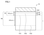
- FIG. 1 is a schematic cross-sectional view illustrating one embodiment of a cutting tool according to the present disclosure.
- FIG. 2 is a schematic cross-sectional view illustrating another embodiment of the cutting tool of the present disclosure.
- FIG. 3 is a schematic cross-sectional view illustrating another embodiment of the cutting tool of the present disclosure.
- FIG. 4 is a schematic cross-sectional view of an example of a CVD (Chemical Vapor Deposition) apparatus used in manufacturing the cutting tool of the present disclosure.
- CVD Chemical Vapor Deposition
- a cutting tool is used in the interrupted turning of cast iron, which includes a substrate and a coating disposed on the substrate, the coating including a first layer, the substrate being made of a hard phase and a binder phase, the hard phase being made of tungsten carbide particles, the binder phase being made of metal cobalt, and the first layer being made of aluminum oxide or titanium aluminum nitride.
- the present disclosure therefore aims to provide a cutting tool that has a long tool life, particularly in intermittent turning of cast iron.
- the cutting tool of the present disclosure comprises: 1. A cutting tool comprising a substrate and a coating disposed on the substrate, The coating comprises a first layer, The substrate comprises a hard phase and a binder phase, the hard phase consists of tungsten carbide particles, the binder phase is made of metallic cobalt; the first layer is made of aluminum oxide or titanium aluminum nitride; The substrate has a first region, the first region is a region sandwiched between the interface between the substrate and the coating and a virtual plane VS1 that passes through a position 0.5 ⁇ m away from the interface toward the substrate and is parallel to the interface, a ratio of a total length of a line segment located in the straight line and the binder phase to a length of a straight line included in a virtual plane VS2 having an equal distance from the interface and an equal distance from the virtual plane VS1 is 50% or more and 90% or less, The surface of the substrate in contact
- the ratio of the total length of the line segment located in the straight line and the bonding phase to the length of a straight line included in a virtual plane VS2 that is equidistant from the interface and from the virtual plane VS1 is measured on a cross section along a normal direction of the interface between the substrate and the coating
- the roughness Rz JIS of the surface of the substrate in contact with the coating can be measured in accordance with JIS B0601:2001 on the cross section along the normal direction of the interface between the substrate and the coating.
- the base material has a second region, the second region is a region sandwiched between the interface between the substrate and the coating and a virtual plane VS3 that passes through a position 2.0 ⁇ m away from the interface toward the substrate and is parallel to the interface,
- the ratio of the voids in the second region may be 0 volume % or more and 1.5 volume % or less. This makes it possible to provide a cutting tool having a longer tool life, particularly in interrupted turning of cast iron.
- the proportion of the voids in the second region can be measured in a cross section along the normal direction of the interface between the substrate and the coating.
- the coating further includes a second layer, the first layer is disposed on the second layer;
- the second layer may consist of titanium carbonitride, which provides a cutting tool with a longer tool life, especially in interrupted turning of cast iron.
- the thickness of the second layer may be greater than 0 ⁇ m and less than or equal to 10 ⁇ m. This makes it possible to provide a cutting tool with a longer tool life, particularly in intermittent turning of cast iron.
- the particle size of the tungsten carbide particles may be 0.3 ⁇ m or more and 3.0 ⁇ m or less. This makes it possible to provide a cutting tool with a longer tool life, especially in intermittent turning of cast iron.
- the base material may contain 8.0 volume % or more and 20 volume % or less of the binder phase. This makes it possible to provide a cutting tool with a longer tool life, especially in intermittent turning of cast iron.
- a ⁇ B means the upper and lower limits of a range (i.e., greater than or equal to A and less than or equal to B). If no unit is stated for A and only a unit is stated for B, the units of A and B are the same.
- FIG. 1 One embodiment of the present disclosure (hereinafter also referred to as “the present embodiment”) is A cutting tool 10 comprising a substrate 1 and a coating 2 disposed on the substrate 1,
- the coating 2 comprises a first layer 3,
- the substrate 1 comprises a hard phase and a binder phase, the hard phase consists of tungsten carbide particles; the binder phase is made of metallic cobalt;
- the first layer 3 is made of aluminum oxide or titanium aluminum nitride,
- the substrate 1 has a first region R1,
- the first region R1 is a region sandwiched between the interface between the substrate 1 and the coating 2 and a virtual plane VS1 that passes through a position 0.5 ⁇ m away from the interface toward the substrate 1 and is parallel to the interface, the ratio of the total length of the straight line and the line segment located in the binder phase (hereinafter also referred to as "L2”) to the length of a straight line included in
- the substrate 1 has a first region R1, which is a region sandwiched between the interface between the substrate 1 and the coating 2 and an imaginary plane VS1 that passes through a position 0.5 ⁇ m away from the interface on the substrate 1 side and is parallel to the interface, and the ratio of the total length (L2) of the straight line and the line segment located in the bonding phase to the length (L1) of the straight line included in the imaginary plane VS2 that is the same distance from the interface and from the imaginary plane VS1 is 50% or more and 90% or less. This improves the adhesion between the substrate 1 and the coating 2, thereby improving the "wear resistance" and "fracture resistance".
- the roughness Rz JIS of the surface of the substrate 1 in contact with the coating 2 is 1.0 ⁇ m or less. This makes it easier for the coating 2 to be formed uniformly, which improves the strength of the coating 2 and thereby improves the "wear resistance” and "fracture resistance”.
- the cutting tool 10 can combine excellent "wear resistance” and excellent “fracture resistance,” making it possible to provide a cutting tool with a long tool life, especially in intermittent turning of cast iron.
- the part of the substrate 1 involved in cutting refers to a region of the substrate 1 surrounded by a cutting edge ridge and a virtual surface whose distance from the cutting edge ridge to the substrate 1 along a perpendicular line to the tangent line of the cutting edge ridge is, for example, 5 mm, 3 mm, 2 mm, 1 mm, or 0.5 mm, depending on the size and shape of the substrate 1.
- the cutting tool 10 of this embodiment can be suitably used as a cutting tool 10 such as a drill, an end mill, an indexable cutting tip for a drill, an indexable cutting tip for an end mill, an indexable cutting tip for milling, an indexable cutting tip for turning, a metal saw, a gear cutting tool, a reamer, and a tap.
- a cutting tool 10 such as a drill, an end mill, an indexable cutting tip for a drill, an indexable cutting tip for an end mill, an indexable cutting tip for milling, an indexable cutting tip for turning, a metal saw, a gear cutting tool, a reamer, and a tap.
- the substrate 1 is composed of a hard phase and a binder phase.
- “composed of a hard phase and a binder phase” means that other hard phases (e.g., carbides, nitrides, carbonitrides, etc. of Ti, Ta, Nb, etc., and mixtures thereof) may be included as long as the effects of the present disclosure are not impaired.
- the substrate 1 may contain 80% to 92% by volume of the hard phase.
- the content of the hard phase in the substrate 1 may be 80% to 92% by volume. This allows the cutting tool 1 to have a longer tool life, especially in intermittent turning of cast iron.
- the lower limit of the content of the hard phase in the substrate 1 may be 80% by volume or more, 81% by volume or more, or 82% by volume or more.
- the upper limit of the content of the hard phase in the substrate 1 may be 92% by volume or less, 91% by volume or less, or 90% by volume or less.
- the content of the hard phase in the substrate 1 may be 81% by volume or more and 91% by volume or less, or 82% by volume or more and 90% by volume or less.
- the substrate 1 may contain 8.0 vol. % or more and 20 vol. % or less of the binder phase.
- the content of the binder phase in the substrate 1 may be 8.0 vol. % or more and 20 vol. % or less. This allows the cutting tool 1 to have a longer tool life, especially in intermittent turning of cast iron.
- the lower limit of the content of the binder phase in the substrate 1 may be 8.0 vol. % or more, 9.0 vol. % or more, or 10.0 vol. % or more.
- the upper limit of the content of the binder phase in the substrate 1 may be 20 vol. % or less, 19 vol. % or less, or 18 vol. % or less.
- the content of the binder phase in the substrate 1 may be 9.0 vol. % or more and 19 vol. % or less, or 10.0 vol. % or more and 18 vol. % or less.
- the “content of the hard phase in the substrate 1" and the “content of the bonding phase in the substrate 1” are determined by the following method. First, a 5000x image is obtained of an arbitrary cross section of the substrate 1 using a scanning electron microscope (SEM). In the image, an arbitrary "rectangular field of view of 10 ⁇ m ⁇ 10 ⁇ m" is identified. Next, in the rectangular field of view, the area of the hard phase and the area of the bonding phase are each measured using image analysis software (ImageJ, version 1.51j8: https://imagej.nih.gov/ij/). Next, the ratio of the area of the hard phase to the area of the rectangular field of view is calculated as a percentage to determine the "content of the hard phase in the substrate 1".
- the ratio of the area of the bonding phase to the area of the rectangular field of view is calculated as a percentage to determine the "content of the bonding phase in the substrate 1". Furthermore, it has been confirmed that as long as measurements are taken on the same substrate 1, there is no variation in the measurement results even if the measurement location is selected arbitrarily.
- the hard phase is made of tungsten carbide particles.
- the substrate 1 has an excellent balance between hardness and strength, particularly at high temperatures, and when used in a cutting tool 10, the substrate 1 can contribute to extending the life of the cutting tool 10.
- "made of tungsten carbide particles” means that other metal elements, precipitates, etc. may be included as long as they do not impair the effects of the present disclosure. Examples of other metal elements include Ni, Cr, Fe, etc. Examples of precipitates include TiC, TiCN, NbC, etc.
- the composition of the hard phase can be determined by performing a mapping analysis on a cross section of any substrate 1 using an energy dispersive X-ray analyzer (EDS) attached to a scanning electron microscope (SEM). It has been confirmed that, as long as measurements are taken on the same substrate 1, there is no variation in the measurement results even if the measurement location is arbitrarily selected.
- EDS energy dispersive X-ray analyzer
- SEM scanning electron microscope
- the particle size of the tungsten carbide particles may be 0.3 ⁇ m or more and 3.0 ⁇ m or less. This makes it easier to achieve a better balance between hardness and toughness, so that the cutting tool 1 has a longer tool life, especially in intermittent turning of cast iron.
- the lower limit of the particle size of the tungsten carbide particles may be 0.3 ⁇ m or more, 0.5 ⁇ m or more, or 0.7 ⁇ m or more.
- the upper limit of the particle size of the tungsten carbide particles may be 3.0 ⁇ m or less, 2.6 ⁇ m or less, or 2.5 ⁇ m or less.
- the particle size of the tungsten carbide particles may be 0.5 ⁇ m or more and 2.6 ⁇ m or less, or 0.7 ⁇ m or more and 2.5 ⁇ m or less.
- the particle size of the tungsten carbide particles can be determined by the following method. First, an arbitrary cross section of the substrate 1 is obtained, and the cross section is mirror-finished to obtain a machined surface. Next, a photograph of the machined surface is taken at a magnification of 5000 times using a scanning electron microscope to obtain a photographed image. Next, for any "20 ⁇ m x 20 ⁇ m rectangular measurement field" in the photographed image, the particle size (Heywood diameter: equivalent diameter of a circle with equal area) of 20 WC particles is measured using image analysis software (ImageJ, version 1.51j8: https://imagej.nih.gov/ij/).
- the same measurement is performed for each of the other four arbitrary "20 ⁇ m x 20 ⁇ m rectangular measurement fields" in the photographed image.
- the "particle size of tungsten carbide particles” is calculated by calculating the average particle size (Heywood diameter: diameter equivalent to a circle with equal area) of a total of 100 WC particles.
- the binder phase is made of metallic cobalt.
- "made of metallic cobalt” means that other metal elements, precipitates, etc. may be included as long as the effect of the present disclosure is not impaired. Examples of other metal elements include Ni, Cr, Fe, etc. Examples of precipitates include TiC, TiCN, NbC, etc.
- composition of the bonding phase can be determined by performing mapping analysis on any cross section using EDS associated with the SEM.
- the roughness Rz JIS of the surface of the substrate 1 in contact with the coating 2 is 1.0 ⁇ m or less. This can improve the "wear resistance” and "fracture resistance".
- the lower limit of the roughness Rz JIS of the surface of the substrate 1 in contact with the coating 2 may be 0 ⁇ m or more, but from the viewpoint of manufacturing, it can be, for example, 0.1 ⁇ m or more, 0.2 ⁇ m or more, or 0.3 ⁇ m or more.
- the upper limit of the roughness Rz JIS of the surface of the substrate 1 in contact with the coating 2 may be 0.9 ⁇ m or less, 0.8 ⁇ m or less, or 0.7 ⁇ m or less.
- the roughness Rz JIS of the surface of the substrate 1 in contact with the coating 2 may be 0 ⁇ m or more and 1.0 ⁇ m or less, 0 ⁇ m or more and 0.9 ⁇ m or less, or 0 ⁇ m or more and 0.8 ⁇ m or less.
- the "ten-point average roughness of the interface" in the observation field is specified by extracting interface contour information using image analysis software (ImageJ, version 1.51j8: https://imagej.nih.gov/ij/) for the observation field.
- image analysis software ImageJ, version 1.51j8: https://imagej.nih.gov/ij/
- the "ten-point average roughness of the interface” is determined for any other four observation fields.
- the roughness Rz JIS of the surface of the substrate 1 in contact with the coating 2 is determined by calculating the average value of the "ten-point average roughness of the interface" for a total of five observation fields.
- the substrate 1 has a first region R1.
- the first region R1 is a region sandwiched between the interface between the substrate 1 and the coating 2 and a virtual plane VS1 that passes through a position 0.5 ⁇ m away from the interface toward the substrate 1 and is parallel to the interface.
- the ratio of the sum of the lengths (L2) of the straight line and the line segments located in the bonding phase to the length (L1) of the straight line included in the virtual plane VS2, which has the same distance from the interface and the virtual plane VS1, is 50% or more and 90% or less. This can improve the "wear resistance” and "fracture resistance" of the cutting tool 1.
- the lower limit of the ratio may be 55% or more, 60% or more, or 65% or more.
- the upper limit of the ratio may be 85% or less, 80% or less, or 75% or less.
- the ratio may be 55% or more and 85% or less, 60% or more and 80% or less, or 65% or more and 75% or less.
- the ratio of the sum of the lengths (L2) of the straight line and the line segments located in the bonding phase to the length (L1) of the straight line included in the virtual plane VS2, which has the same distance from the interface and the virtual plane VS1, can be measured on a cross section along the normal direction of the interface between the substrate 1 and the coating 2. More specifically, first, an observation image of the cross section is taken at a magnification of 1000 times using a scanning electron microscope. Next, an arbitrary "20 ⁇ m ⁇ 20 ⁇ m rectangular field of view" is identified in the observation image. Here, the straight line passes through any pair of two opposing sides in the rectangular field of view.
- L1 and L2 are measured on the straight line in the rectangular field of view using image analysis software (ImageJ, version 1.51j8: https://imagej.nih.gov/ij/).
- ImageJ image analysis software
- the proportion of voids in the second region R2 can be measured in a cross section along the normal direction of the interface between the substrate 1 and the coating 2. More specifically, an image is first obtained by capturing an image at a magnification of 1000x using an SEM in a cross section along the normal direction of the interface between the substrate 1 and the coating 2. Next, in the image, an arbitrary rectangular observation field of 10 ⁇ m x 10 ⁇ m is identified at a magnification of 10,000x. In the observation field, the interface is assumed to pass through any pair of two opposing sides.
- the thickness of the coating 2 may be 2.0 ⁇ m or more and 20 ⁇ m or less. If the lower limit of the thickness of the coating 2 is less than 2.0 ⁇ m, the tool life tends to be insufficient. If the upper limit of the thickness of the coating 2 exceeds 20 ⁇ m, stress is generated in the coating 2 during cutting, and peeling or breakage tends to occur easily.
- the lower limit of the thickness of the coating 2 may be 2.0 ⁇ m or more, 3.0 ⁇ m or more, or 4.0 ⁇ m or more.
- the upper limit of the thickness of the coating 2 may be 20 ⁇ m or less, 19 ⁇ m or less, or 18 ⁇ m or less.
- the thickness of the coating 2 may be 3.0 ⁇ m or more and 19 ⁇ m or less, or 4.0 ⁇ m or more and 18 ⁇ m or less.
- the thickness of the coating 2 can be determined by the following method. It can be measured by observing a cross section along the normal direction of the interface between the substrate 1 and coating 2 using a scanning electron microscope (SEM). Specifically, the observation magnification of the cross-sectional sample is set to 1000x, the observation field is a rectangular field of 120 ⁇ m x 100 ⁇ m, the thickness width is measured at three points in one field of view, and the average value is taken as the "thickness.” The same applies to the thickness of each layer described below unless otherwise specified.
- SEM scanning electron microscope
- the coating 2 includes a first layer 3.
- the first layer 3 is made of aluminum oxide or titanium aluminum nitride. This makes it possible to suppress a reaction between the cutting tool 10 and the workpiece.
- "made of aluminum oxide or titanium aluminum nitride" here means that other components may be included as long as they do not impair the effects of the present disclosure. Examples of other components include C atoms, Cr atoms, etc.
- the composition of the first layer 3 can be determined by performing point analysis on any cross section using an EDS attached to an SEM. It has been confirmed that there is no variation in the measurement results even if the measurement points are arbitrarily selected, as long as the measurements are performed using the same cutting tool 10.
- the coating 2 may further include a second layer 4, the first layer 3 being disposed on the second layer 4, and the second layer 4 may be made of titanium carbonitride.
- "made of titanium carbonitride" here means that other components may be included as long as they do not impair the effects of the present disclosure. Examples of other components include Si atoms.
- composition of the second layer 4 can be determined by performing point analysis on any cross section using an EDS attached to an SEM. It has been confirmed that there is no variation in the measurement results even if the measurement points are arbitrarily selected, as long as the measurements are performed using the same cutting tool 10.
- the thickness of the second layer 4 may be more than 0 ⁇ m and not more than 10 ⁇ m. This allows the cutting tool 1 to have a longer tool life, especially in the intermittent turning of cast iron.
- the lower limit of the thickness of the second layer 4 may be more than 0 ⁇ m, may be 1 ⁇ m or more, or may be 2 ⁇ m or more.
- the upper limit of the thickness of the second layer 4 may be 10 ⁇ m or less, may be 9 ⁇ m or less, or may be 8 ⁇ m or less.
- the thickness of the second layer 4 may be 1 ⁇ m or more and 9 ⁇ m or less, or may be 2 ⁇ m or more and 8 ⁇ m or less.
- the coating 2 further includes a base layer 5 in contact with the substrate 1, and the base layer 5 may be made of titanium nitride. This allows for a longer tool life, especially in intermittent turning of cast iron.
- the coating 2 further includes a base layer 5 in contact with the substrate 1 and the coating 2 further includes a second layer 4, the second layer 4 is disposed on the base layer 5, and the first layer 3 is disposed on the second layer 4.
- the coating 2 further includes a base layer 5 in contact with the substrate 1 and the coating 2 does not include the second layer 4, the first layer 3 is disposed on the base layer 5.
- "made of titanium nitride" here means that other components may be contained as long as they do not impair the effects of the present disclosure. Examples of other components include O atoms.
- the composition of the base layer 5 can be determined by performing point analysis on any cross section using an EDS attached to an SEM. It has been confirmed that there is no variation in the measurement results even if the measurement points are arbitrarily selected, as long as the measurements are performed using the same cutting tool 10.
- the thickness of the underlayer 5 may be 0.1 ⁇ m or more and 1.0 ⁇ m or less. This allows the cutting tool 1 to have a longer tool life, especially in the intermittent turning of cast iron.
- the lower limit of the thickness of the underlayer 5 may be 0.1 ⁇ m or more, 0.2 ⁇ m or more, or 0.3 ⁇ m or more.
- the upper limit of the thickness of the underlayer 5 may be 1.0 ⁇ m or less, 0.9 ⁇ m or less, or 0.8 ⁇ m or less.
- the thickness of the underlayer 5 may be 0.2 ⁇ m or more and 0.9 ⁇ m or less, or 0.3 ⁇ m or more and 0.8 ⁇ m or less.
- the coating 2 may further include other layers.
- the other layers include, for example, a "first intermediate layer located between the first layer 3 and the second layer 4" (not shown), a “second intermediate layer located between the second layer 4 and the underlayer 5" (not shown), and a "surface layer located on the surface of the coating 2" (not shown).
- the other layers include, for example, a "first intermediate layer located between the first layer 3 and the second layer 4" (not shown) and a "surface layer located on the surface of the coating 2" (not shown).
- the other layers include, for example, a "third intermediate layer located between the first layer 3 and the underlayer 5" (not shown) and a "surface layer located on the surface of the coating 2" (not shown).
- FIG. 4 is a schematic cross-sectional view of an example of a CVD apparatus used in the manufacture of the cutting tool of this embodiment.
- the manufacturing method of the cutting tool of this embodiment is the manufacturing method of the cutting tool described in embodiment 1, and includes a first step of preparing a substrate and a second step of forming a coating on the substrate.
- the first step includes, in this order, a 1A step of mixing tungsten carbide powder (WC powder) and cobalt powder (Co powder) to obtain a mixed powder, a 1B step of drying the mixed powder and then forming the mixed powder into a predetermined shape to obtain a molded body, a 1C step of sintering the molded body to obtain a substrate intermediate, and a 1D step of performing a surface treatment on the substrate intermediate to obtain a substrate.
- the second step includes a 2A step of forming a first layer by a CVD method.
- a mixed powder is obtained by mixing WC powder and Co powder.
- a ball mill or the like can be used for mixing.
- other materials can be mixed. Examples of the other materials include TiC, TiCN, and NbC.
- the composition of the mixed powder can be, for example, as follows, with respect to 100 parts by mass of the mixed powder. (Composition of mixed powder) WC powder: 88 parts by mass or more and 95 parts by mass or less Co powder: 5 parts by mass or more and 12 parts by mass or less
- step 1C the green body is sintered to obtain a substrate intermediate. More specifically, the sintering can be carried out under the following conditions. (Sintering conditions) Sintering temperature: 1300°C to 1500°C Sintering time: 40 minutes to 90 minutes
- the proportion of voids in the second region can be set to a desired range by using brush polishing as the method for process 1D.
- the proportion of voids in the second region can be set to a desired range by using brush polishing as the method for process 1D and setting the temperature inside the reaction vessel 32 in process 2B to less than 900°C.
- the material of the brush used for brush polishing can be, for example, diamond abrasive grains or ceramic abrasive grains.
- the abrasive grain size of the diamond abrasive grains and the abrasive grain size of the ceramic abrasive grains can be, for example, 10 ⁇ m or more and 100 ⁇ m or less.
- a coating is formed on the substrate to obtain a cutting tool.
- the coating is formed, for example, by using a CVD apparatus shown in FIG. 4.
- the CVD apparatus 30 includes a plurality of substrate setting jigs 31 for holding the substrate 1, and a heat-resistant alloy steel reaction vessel 32 that covers the substrate setting jigs 31.
- a temperature control device 33 for controlling the temperature inside the reaction vessel 32 is provided around the reaction vessel 32.
- the reaction vessel 32 is provided with a gas introduction pipe 35 having a gas introduction port 34.
- the gas introduction pipe 35 is arranged to extend vertically in the internal space of the reaction vessel 32 in which the substrate setting jigs 31 are arranged, and is arranged to be rotatable about the vertical axis, and is provided with a plurality of ejection holes (through holes 36) for ejecting gas into the reaction vessel 32.
- the first layer, the second layer, and the underlayer that constitute the coating can be formed as follows.
- the second step may further include a step of forming the "other layer.”
- the “other layer” may be formed by a conventional method.
- Step 2A Step of forming first layer by CVD method>
- the first layer is formed by a CVD method. More specifically, in the substrate setting jig 31 in which the substrate 10 is placed, a reaction gas for the first layer is introduced into the reaction vessel 32 from the gas introduction pipe 35 while controlling the temperature and pressure in the reaction vessel 32 within a predetermined range. As a result, the first layer is formed on the substrate 10.
- the content of AlCl3 in the mixed gas may be 0.7% by volume or more and 2.0% by volume or less.
- the content of TiCl4 in the mixed gas may be 0% by volume or more and 0.2% by volume or less.
- the content of CO2 in the mixed gas may be 0% by volume or more and 4.5% by volume or less.
- the content of H2S in the mixed gas may be 0% by volume or more and 0.2% by volume or less.
- the content of NH3 in the mixed gas may be 0% by volume or more and 2.8% by volume or less.
- the content of HCl in the mixed gas may be 0.2% by volume or more and 3.5% by volume or less.
- the content of N2 in the mixed gas may be 0% by volume or more and 35% by volume or less.
- the content of H2 in the mixed gas may be 60% by volume or more and 95% by volume or less.
- the flow rate of the reactant gas for the first layer (in other words, the total gas flow rate for the first layer) may be 50 L/min or more and 70 L/min or less.
- the temperature inside the reaction vessel 32 is controlled to be 850°C or higher and 1000°C or lower.
- the pressure inside the reaction vessel 32 may be controlled to be 3.0 kPa or higher and 7.0 kPa or lower.
- the gas introduction pipe 35 may be rotated when introducing the gas.
- the state of the first layer can be changed by controlling each condition of the CVD method.
- the thickness of the first layer can be controlled by adjusting the deposition time.
- Step 2B Step of forming second layer by CVD method>
- the second layer is formed by a CVD method. More specifically, before step 2A is performed, in the substrate setting jig 31 in which the substrate 10 is placed, a reaction gas for the second layer is introduced into the reaction vessel 32 from the gas introduction pipe 35 while controlling the temperature and pressure in the reaction vessel 32 within a predetermined range. This forms the second layer.
- the reactive gas for the second layer may be a mixture of TiCl 4 , CH 3 CN, and H 2 .
- the TiCl4 content in the mixed gas may be 1.0 vol% or more and 3.0 vol% or less.
- the CH3CN content in the mixed gas may be 0.5 vol% or more and 1.0 vol% or less.
- the H2 content in the mixed gas may be 96 vol% or more and 98.5 vol% or less.
- the flow rate of the reaction gas for the second layer (in other words, the total gas flow rate for the second layer) may be 50 L/min or more and 60 L/min or less.
- the state of the second layer can be changed by controlling each condition of the CVD method.
- the thickness of the second layer can be controlled by adjusting the deposition time.
- ⁇ Second C step step of forming underlayer by CVD method>
- the underlayer is formed by the CVD method. More specifically, when the 2C step includes the 2B step, before the 2B step is performed, in the substrate set jig 31 in which the substrate 10 is placed, the reaction gas for the underlayer is introduced from the gas introduction pipe 35 into the reaction vessel 32 while controlling the temperature and pressure in the reaction vessel 32 to a predetermined range.
- the reaction gas for the underlayer is introduced from the gas introduction pipe 35 into the reaction vessel 32 while controlling the temperature and pressure in the reaction vessel 32 to a predetermined range. As a result, the underlayer is formed.
- a mixed gas of TiCl 4 , N 2 and H 2 can be used as a source gas for the underlayer.
- the TiCl4 content in the mixed gas may be 1% by volume or more and 3% by volume or less.
- the N2 content in the mixed gas may be 38% by volume or more and 42% by volume or less.
- the H2 content in the mixed gas may be 55% by volume or more and 61% by volume or less.
- the flow rate of the reactive gas for the underlayer (in other words, the total gas flow rate for the underlayer) may be 60 L/min or more and 70 L/min or less.
- the state of the underlayer can be changed by controlling each condition of the CVD method.
- the thickness of the underlayer can be controlled by adjusting the deposition time.
- the second step may include, in addition to the above steps, a surface treatment step such as surface grinding or shot blasting.
- a mixed powder was obtained by mixing "Uniform Grain Tungsten Carbide Powder” (trademark), which is a WC powder manufactured by A.L.M.T. Corp., and Co powder (average particle size: 2.0 ⁇ m) using a ball mill. At that time, the WC powder and Co powder were used in the amounts shown in Tables 1 and 2 relative to 100 parts by mass of the mixed powder.
- Step 1B> The mixed powder was dried at 500° C. for 30 minutes, and then molded into the shape of “CNMG120408N-GZ” manufactured by Sumitomo Electric Hardmetal Corp. to obtain a molded body.
- a first layer was formed by CVD under the conditions described in Tables 7 and 8 to have the thicknesses described in Tables 11 and 12.
- a first layer was formed by CVD under the conditions described in Table 7 to have the thicknesses described in Tables 11 and 12.
- the underlayers of sample 4 and samples 104 to 106 a first layer was formed by CVD under the conditions described in Tables 7 and 8 to have the thicknesses described in Tables 11 and 12.
- composition of the hard phase of each sample cutting tool was determined by the method described in embodiment 1. The results obtained are shown in the "Composition” column of the “Hard Phase” column in Tables 9 and 10. When “WC particles” is written in the “Composition” column of the “Hard Phase” column in Tables 9 and 10, it means that the hard phase is composed of tungsten carbide particles.
- composition of the binder phase of each cutting tool sample was determined by the method described in embodiment 1. The results are shown in the "composition” column of the "binder phase” column in Tables 9 and 10. When “metallic Co” is written in the “composition” column of the “binder phase” column in Tables 9 and 10, it means that the binder phase is made of metallic cobalt.
- composition of the underlayer of each sample cutting tool was determined by the method described in embodiment 1. The results obtained are shown in the "Composition” column of the "Underlayer” column in Tables 11 and 12. When “TiN” is written in the “Composition” column of the “Underlayer” column in Tables 11 and 12, it means that the underlayer is made of titanium nitride. When “-" is written in the "Composition” column of the "Underlayer” column in Tables 11 and 12, it means that no underlayer is present.
- composition of the second layer of each sample cutting tool was determined by the method described in embodiment 1. The results obtained are shown in the "Composition” column of the “Second Layer” column in Tables 11 and 12.
- TiCN is written in the "Composition” column of the “Second Layer” column in Tables 11 and 12, it means that the second layer is made of titanium carbonitride.
- - is written in the "Composition” column of the “Second Layer” column in Tables 11 and 12, it means that the second layer is not present.
- composition of the first layer of each sample cutting tool was determined by the method described in embodiment 1. The results obtained are shown in the "Composition” column of the “First Layer” column in Tables 11 and 12.
- Al 2 O 3 is written in the "Composition” column of the “First Layer” column in Tables 11 and 12, it means that the first layer is made of aluminum oxide.
- AlTiN is written in the "Composition” column of the “First Layer” column in Tables 11 and 12, it means that the first layer is made of titanium aluminum nitride.
- Cutting tools related to samples 1 to 24 correspond to examples.
- Cutting tools related to samples 101 to 106 correspond to comparative examples. From the results in Tables 11 and 12, it was found that cutting tools related to samples 1 to 24 have a longer tool life even in intermittent turning of cast iron than cutting tools related to samples 101 to 106.
Landscapes
- Engineering & Computer Science (AREA)
- Mechanical Engineering (AREA)
- Cutting Tools, Boring Holders, And Turrets (AREA)
- Chemical Vapour Deposition (AREA)
Priority Applications (3)
| Application Number | Priority Date | Filing Date | Title |
|---|---|---|---|
| JP2024507143A JP7841675B2 (ja) | 2023-07-26 | 2023-07-26 | 切削工具 |
| PCT/JP2023/027368 WO2025022602A1 (ja) | 2023-07-26 | 2023-07-26 | 切削工具 |
| JP2025053254A JP2025094246A (ja) | 2023-07-26 | 2025-03-27 | 切削工具 |
Applications Claiming Priority (1)
| Application Number | Priority Date | Filing Date | Title |
|---|---|---|---|
| PCT/JP2023/027368 WO2025022602A1 (ja) | 2023-07-26 | 2023-07-26 | 切削工具 |
Publications (1)
| Publication Number | Publication Date |
|---|---|
| WO2025022602A1 true WO2025022602A1 (ja) | 2025-01-30 |
Family
ID=94374732
Family Applications (1)
| Application Number | Title | Priority Date | Filing Date |
|---|---|---|---|
| PCT/JP2023/027368 Pending WO2025022602A1 (ja) | 2023-07-26 | 2023-07-26 | 切削工具 |
Country Status (2)
| Country | Link |
|---|---|
| JP (2) | JP7841675B2 (https=) |
| WO (1) | WO2025022602A1 (https=) |
Citations (6)
| Publication number | Priority date | Publication date | Assignee | Title |
|---|---|---|---|---|
| JPH10226597A (ja) * | 1997-02-12 | 1998-08-25 | Toshiba Tungaloy Co Ltd | ダイヤモンド被覆硬質部材 |
| JP2015123530A (ja) * | 2013-12-26 | 2015-07-06 | 住友電工ハードメタル株式会社 | 切削工具 |
| WO2018105403A1 (ja) * | 2016-12-09 | 2018-06-14 | 住友電工ハードメタル株式会社 | 表面被覆切削工具 |
| JP2020200803A (ja) * | 2019-06-12 | 2020-12-17 | Tpr株式会社 | ピストンリング |
| JP2021088039A (ja) * | 2019-12-05 | 2021-06-10 | 三菱マテリアル株式会社 | 表面被覆切削工具 |
| WO2023277077A1 (ja) * | 2021-06-30 | 2023-01-05 | 住友電工ハードメタル株式会社 | 切削工具 |
-
2023
- 2023-07-26 WO PCT/JP2023/027368 patent/WO2025022602A1/ja active Pending
- 2023-07-26 JP JP2024507143A patent/JP7841675B2/ja active Active
-
2025
- 2025-03-27 JP JP2025053254A patent/JP2025094246A/ja active Pending
Patent Citations (6)
| Publication number | Priority date | Publication date | Assignee | Title |
|---|---|---|---|---|
| JPH10226597A (ja) * | 1997-02-12 | 1998-08-25 | Toshiba Tungaloy Co Ltd | ダイヤモンド被覆硬質部材 |
| JP2015123530A (ja) * | 2013-12-26 | 2015-07-06 | 住友電工ハードメタル株式会社 | 切削工具 |
| WO2018105403A1 (ja) * | 2016-12-09 | 2018-06-14 | 住友電工ハードメタル株式会社 | 表面被覆切削工具 |
| JP2020200803A (ja) * | 2019-06-12 | 2020-12-17 | Tpr株式会社 | ピストンリング |
| JP2021088039A (ja) * | 2019-12-05 | 2021-06-10 | 三菱マテリアル株式会社 | 表面被覆切削工具 |
| WO2023277077A1 (ja) * | 2021-06-30 | 2023-01-05 | 住友電工ハードメタル株式会社 | 切削工具 |
Also Published As
| Publication number | Publication date |
|---|---|
| JPWO2025022602A1 (https=) | 2025-01-30 |
| JP2025094246A (ja) | 2025-06-24 |
| JP7841675B2 (ja) | 2026-04-07 |
Similar Documents
| Publication | Publication Date | Title |
|---|---|---|
| US10717135B2 (en) | Coated tool | |
| CN107530784B (zh) | 表面被覆切削工具及其制造方法 | |
| CN107438490B (zh) | 表面被覆切削工具及其制造方法 | |
| US20160136786A1 (en) | Coated cutting tool | |
| JP7135261B1 (ja) | 切削工具 | |
| CN107427930B (zh) | 被覆工具 | |
| JP7416327B1 (ja) | 切削工具 | |
| JP7135250B1 (ja) | 切削工具 | |
| CN117957079B (zh) | 切削工具 | |
| WO2025022602A1 (ja) | 切削工具 | |
| WO2017057456A1 (ja) | 被覆工具 | |
| JP7852829B1 (ja) | 切削工具 | |
| JP7581588B1 (ja) | 切削工具 | |
| JP7750434B1 (ja) | 切削工具 | |
| JP7852830B1 (ja) | 切削工具 | |
| JP7754348B1 (ja) | 切削工具 | |
| JP7679935B1 (ja) | 切削工具 | |
| JP7581587B1 (ja) | 切削工具 | |
| JP7666740B1 (ja) | 切削工具 | |
| KR102727225B1 (ko) | 절삭 공구 | |
| WO2024261953A1 (ja) | 切削工具 | |
| CN113905842B (zh) | 切削工具 |
Legal Events
| Date | Code | Title | Description |
|---|---|---|---|
| WWE | Wipo information: entry into national phase |
Ref document number: 2024507143 Country of ref document: JP |
|
| 121 | Ep: the epo has been informed by wipo that ep was designated in this application |
Ref document number: 23946685 Country of ref document: EP Kind code of ref document: A1 |
|
| NENP | Non-entry into the national phase |
Ref country code: DE |