WO2025018326A1 - 超音波眼圧計および眼科用超音波アクチュエータ - Google Patents
超音波眼圧計および眼科用超音波アクチュエータ Download PDFInfo
- Publication number
- WO2025018326A1 WO2025018326A1 PCT/JP2024/025420 JP2024025420W WO2025018326A1 WO 2025018326 A1 WO2025018326 A1 WO 2025018326A1 JP 2024025420 W JP2024025420 W JP 2024025420W WO 2025018326 A1 WO2025018326 A1 WO 2025018326A1
- Authority
- WO
- WIPO (PCT)
- Prior art keywords
- ultrasonic
- sonotrode
- reflecting
- tip
- vibration
- Prior art date
- Legal status (The legal status is an assumption and is not a legal conclusion. Google has not performed a legal analysis and makes no representation as to the accuracy of the status listed.)
- Pending
Links
Images




Classifications
-
- A—HUMAN NECESSITIES
- A61—MEDICAL OR VETERINARY SCIENCE; HYGIENE
- A61B—DIAGNOSIS; SURGERY; IDENTIFICATION
- A61B3/00—Apparatus for testing the eyes; Instruments for examining the eyes
- A61B3/10—Objective types, i.e. instruments for examining the eyes independent of the patients' perceptions or reactions
-
- A—HUMAN NECESSITIES
- A61—MEDICAL OR VETERINARY SCIENCE; HYGIENE
- A61B—DIAGNOSIS; SURGERY; IDENTIFICATION
- A61B3/00—Apparatus for testing the eyes; Instruments for examining the eyes
- A61B3/10—Objective types, i.e. instruments for examining the eyes independent of the patients' perceptions or reactions
- A61B3/16—Objective types, i.e. instruments for examining the eyes independent of the patients' perceptions or reactions for measuring intraocular pressure, e.g. tonometers
Definitions
- the present disclosure relates to an ultrasonic tonometer that uses ultrasonic waves to measure the intraocular pressure of a test eye, and an ophthalmic ultrasonic actuator used in ophthalmic devices such as ultrasonic tonometers.
- Air-injection tonometers are the most common type of non-contact tonometer. Air-injection tonometers measure intraocular pressure based on the deformation of the cornea when air is injected onto the cornea, and the pressure of the air injected onto the cornea.
- ultrasonic tonometers that use ultrasound to measure intraocular pressure have been proposed as non-contact tonometers.
- the ultrasonic tonometer described in Patent Document 1 measures intraocular pressure based on the deformation state of the cornea when ultrasound is radiated to the cornea and the radiation pressure sprayed onto the cornea.
- the ultrasonic tonometer described in Patent Document 2 measures the intraocular pressure of the subject's eye based on the relationship between the characteristics (phase, amplitude) of the reflected wave from the cornea and the intraocular pressure.
- an ophthalmic device that uses ultrasound to measure the characteristics of a test eye, it is necessary to irradiate the test eye with ultrasound of sufficient output.
- ultrasound of sufficient output For example, in order to measure the intraocular pressure of the test eye using ultrasound, it is necessary to irradiate the test eye with ultrasound of very high output.
- the applicant of the present application has not yet achieved irradiation of ultrasound of sufficient output.
- ultrasonic actuators there are actuators that have a flexural vibration part at the axial tip of the sonotrode that propagates ultrasound into the air.
- ultrasonic actuators that have a flexural vibration part may be able to irradiate ultrasound of a test eye with a higher output.
- simply adopting an ultrasonic actuator that has a flexural vibration part has not been able to achieve irradiation of ultrasound of a sufficient output. Therefore, a technology that can emit ultrasound to the test eye with higher efficiency is desired.
- a typical object of the present invention is to provide an ultrasonic tonometer and an ophthalmic ultrasonic actuator capable of emitting ultrasonic waves to a test eye with high efficiency.
- the ultrasonic tonometer provided by a typical embodiment of the present disclosure is an ultrasonic tonometer that uses ultrasonic waves to measure the intraocular pressure of a test eye, and includes an ultrasonic actuator having an ultrasonic element and irradiating ultrasonic waves to the test eye, and the ultrasonic actuator includes a sonotrode that propagates ultrasonic waves generated by the ultrasonic element into the air, a flexural vibration part that is provided at the axial tip side of the sonotrode and flexurally vibrates in response to ultrasonic vibration of the sonotrode, and a reflecting part that covers at least a portion of the circumferential direction of the flexural vibration part while forming a gap between the flexural vibration part, thereby reflecting at least a portion of the ultrasonic waves generated by the flexural vibration part and guiding the direction of irradiation of ultrasonic waves by the ultrasonic actuator toward the axial tip side.
- the ophthalmic ultrasonic actuator provided by a typical embodiment of the present disclosure is an ophthalmic ultrasonic actuator used in an ophthalmic device that irradiates an ultrasonic wave to a test eye, and includes an ultrasonic element that generates ultrasonic waves, a sonotrode that propagates the ultrasonic waves generated by the ultrasonic element into the air, a flexural vibration part that is provided at the axial tip side of the sonotrode and flexurally vibrates in response to the ultrasonic vibration of the sonotrode, and a reflecting part that covers at least a portion of the circumferential direction of the flexural vibration part while forming a gap between the flexural vibration part and the flexural vibration part, thereby reflecting at least a portion of the ultrasonic waves generated by the flexural vibration part and guiding the direction of irradiation of the ultrasonic wave by the ultrasonic actuator toward the axial tip side.
- the ultrasonic tonometer and ophthalmic ultrasonic actuator disclosed herein facilitates the emission of ultrasonic waves to the test eye with high efficiency.
- the ultrasonic tonometer exemplified in this disclosure measures the intraocular pressure of a test eye using ultrasonic waves.
- the ultrasonic tonometer includes an ultrasonic actuator.
- the ultrasonic actuator has an ultrasonic element and irradiates ultrasonic waves to the test eye.
- the ultrasonic actuator of this disclosure includes a sonotrode, a flexural vibration part, and a reflecting part.
- the sonotrode propagates ultrasonic waves generated by the ultrasonic element into the air.
- the flexural vibration part is provided on the axial tip side of the sonotrode and flexibly vibrates in response to ultrasonic vibration of the sonotrode.
- the reflecting part covers at least a portion of the circumferential direction of the flexural vibration part while forming a gap between the flexural vibration part and the reflecting part, thereby reflecting ultrasonic waves generated from the flexural vibration part and guiding the direction of irradiation of ultrasonic waves by the ultrasonic actuator to the axial tip side.
- ultrasonic waves propagating from the deflection vibration section in a direction other than the axial tip side are reflected by the reflecting section and are easily guided toward the axial tip side.
- ultrasonic waves generated by the ultrasonic actuator are easily emitted to the test eye with high efficiency.
- the reflecting section may cover the entire circumferential circumference of the flexible vibration section.
- ultrasonic waves are more easily guided toward the axial tip over the entire circumferential circumference, which further improves the efficiency of ultrasonic emission to the test eye.
- the reflecting section may cover only a portion of the circumferential circumference of the flexible vibration section (for example, only above, only below, only to the sides, or only above and below the sonotrode as viewed from the test eye). Even in this case, ultrasonic waves propagating from the flexible vibration section to the surroundings are more easily guided appropriately toward the test eye by the reflecting section.
- the gap between the flexible vibration portion and the reflecting portion be provided around the entire circumference of the flexible vibration portion.
- ultrasonic waves propagated to the rear end side of the flexible vibration portion are more easily guided to the tip side through the gap provided around the entire circumference. Therefore, ultrasonic waves are more easily emitted to the test eye with higher efficiency.
- the flexible vibration portion and the reflecting portion may be in contact with each other at a portion of the circumference of the flexible vibration portion.
- a mesh-like member may be provided between the flexible vibration portion and the reflecting portion to reduce the possibility of foreign matter entering the gap. Even in this case, ultrasonic waves are more easily guided appropriately to the tip side by the reflecting portion.
- the flexural vibration part and the sonotrode may be formed as one unit.
- the main body part of the sonotrode which has a columnar (e.g., cylindrical) outer shape, may be cut out in an annular shape slightly toward the base end side from the tip end, and the part remaining on the tip side of the cut-out part may be used as the flexural vibration part.
- a sonotrode equipped with a flexural vibration part is appropriately manufactured from one member.
- the shape of the cut-out part when viewed in a cross section including the axis of the sonotrode may be formed in an arc shape or an elliptical arc shape.
- the flexural vibration part and the sonotrode may also be separate members.
- the flexural vibration part may be fixed to the tip end of the sonotrode by a fixing member such as a screw. Even in this case, the flexural vibration part flexurally vibrates, making it easier to irradiate ultrasonic waves with a higher output.
- the ultrasonic actuator may be a Langevin type transducer.
- the Langevin type transducer may include an ultrasonic element, a sonotrode (sometimes called a horn or a front mass), and a back mass.
- the ultrasonic element generates ultrasonic waves.
- the sonotrode propagates ultrasonic waves generated by the ultrasonic element into the air.
- the sonotrode is a mass member disposed on the axial tip side (the side of the subject's eye) of the ultrasonic element.
- the back mass is a mass member disposed on the axial rear end side of the ultrasonic element. The sonotrode and the back mass may be tightened in a direction approaching each other with the ultrasonic element disposed therebetween.
- the Langevin type transducer can generate ultrasonic waves with reduced mechanical and thermal energy loss, and therefore can generate ultrasonic waves with high output.
- the reflecting portion exemplified in this disclosure can be adopted in various ultrasonic actuators equipped with a bending vibration portion.
- the reflecting portion exemplified in this disclosure can also be applied to ultrasonic actuators other than the Langevin type transducer.
- the material of the reflecting part can be selected appropriately, but it is desirable to use a material for the reflecting part that has as large a difference in acoustic impedance as possible with respect to air.
- the reflecting part can be made of aluminum or resin.
- the axial tip of the reflecting section may protrude further toward the tip than the axial tip of the flexural vibration section.
- at least a portion of the ultrasonic waves propagating in the diagonal tip direction as viewed from the flexural vibration section is also reflected by the inner peripheral surface of the reflecting section and emitted toward the subject's eye. Therefore, ultrasonic waves generated by the ultrasonic actuator can be more easily emitted to the subject's eye with higher efficiency.
- the reflecting portion is provided so as to cover at least the rear end side from the position of the flexural vibration portion in the axial direction of the sonotrode.
- the reflecting portion is provided so as to cover the rear end side from the position of the flexural vibration portion, ultrasonic waves propagating axially rearward from the flexural vibration portion are also more easily guided appropriately toward the axial tip side.
- a first inclined surface may be formed on at least a portion of the inner peripheral surface (i.e., the surface facing the axis) at the axial tip of the reflecting part, the closer it is to the tip side, the closer it is to the axis of the sonotrode (i.e., inward).
- the first inclined surface is provided, the ultrasonic waves that pass through the tip opening of the reflecting part are more likely to converge on the object to which the ultrasonic waves are irradiated (in this disclosure, the cornea of the test eye). Therefore, the ultrasonic waves generated by the ultrasonic actuator are more likely to be emitted to the test eye with higher efficiency.
- the first inclined surface can also be expressed as an inclined surface that is inclined to face the rear end side in the axial direction of the sonotrode.
- the range of the axial tip of the inner circumferential surface of the reflecting portion that forms the first inclined surface can be set appropriately.
- the first inclined surface may be formed at least on the inner circumferential surface of the reflecting portion that is closer to the tip than the flexural vibration portion. In this case, the ultrasonic waves are more likely to converge on the target object.
- the first inclined surface is formed at least in the axial direction of the inner circumferential surface of the reflecting portion in the range from the tip position of the flexural vibration portion to the position of the most distal end of the inner circumferential surface of the reflecting portion.
- the first inclined surface is formed in the range from the most distal end of the inner circumferential surface of the reflecting portion to the most distal end of the second inclined surface described later. It is not necessary for the entire inner circumferential surface of the reflecting portion that is closer to the tip than the flexural vibration portion to be the first inclined surface. In other words, it is sufficient that the first inclined surface is formed at a position where the ultrasonic waves are more likely to converge on the target object.
- the inner circumferential surface at the axial tip of the reflecting portion may be formed to be parallel to the axis of the sonotrode. Even in this case, the ultrasonic waves are more likely to be appropriately guided toward the tip by the reflecting portion.
- the outer peripheral surface (i.e., the surface facing away from the axis) at the axial tip of the reflecting part may be formed with an outer peripheral inclined surface that is inclined in a direction approaching the axis of the sonotrode (i.e., inward) as it approaches the tip.
- an outer peripheral inclined surface By providing an outer peripheral inclined surface, it becomes easier to secure space around the reflecting part. This makes it even easier to install an ultrasonic actuator equipped with a reflecting part in a device. For example, even when multiple ultrasonic actuators are arranged as closely as possible, installation of the ultrasonic actuator becomes easier.
- An annular space may be formed around the axis, surrounded by the tip of the main body supporting the flexural vibration part of the sonotrode, the flexural vibration part provided at the tip of the main body, and the inner surface of the reflecting part. At least a part of the inner surface of the reflecting part facing the annular space may be formed with a second inclined surface that is inclined in a direction away from the axis of the sonotrode as it approaches the tip side (i.e., outward). In this case, the ultrasonic waves propagating through the annular space are easily reflected by the second inclined surface toward the tip side in the axial direction.
- the ultrasonic waves propagating from the flexural vibration part to the rear end side in the axial direction are also easily reflected by the second inclined surface toward the tip side in the axial direction.
- unintended phenomena such as diffraction are likely to occur at the corner surrounded by the two surfaces.
- the quality of the ultrasonic waves irradiated to the test eye may be reduced.
- by providing a second inclined surface on the inner peripheral surface of the reflecting portion it is possible to omit or reduce two surfaces adjacent to each other at an angle of 90 degrees or less in the vicinity of the annular space.
- the second inclined surface can also be expressed as an inclined surface that is inclined so as to face the tip side in the axial direction of the sonotrode.
- the range of the inner circumferential surface of the reflecting portion that forms the second inclined surface can be set as appropriate.
- the base end of the second inclined surface may coincide with the base end of the annular space.
- the number of two surfaces adjacent to each other at an angle of 90 degrees or less in the vicinity of the annular space is reduced. This makes it easier for the ultrasonic waves generated by the ultrasonic actuator to be emitted more appropriately toward the subject's eye.
- the distal end of the second inclined surface may be smoothly connected to the proximal end of the first inclined surface. In this case, the ultrasonic waves propagating through the annular space are more easily guided toward the distal end.
- the range of the inner circumferential surface of the reflecting portion that forms the first inclined surface and the second inclined surface may be changed.
- a surface that is parallel to the axis of the sonotrode may be formed between the first inclined surface and the second inclined surface.
- the cross-sectional shape of the second inclined surface formed on the inner peripheral surface of the reflecting portion may be a curved shape that inclines in a direction away from the axis of the sonotrode as it approaches the tip. In this case, ultrasonic waves propagating through the annular space are more easily and efficiently reflected toward the tip by the second inclined surface.
- the cross-sectional shape of the second inclined surface when viewed in a cross section including the axis is formed in a partial arc shape.
- the ultrasound is efficiently reflected toward the tip side.
- the cross-sectional shape of the second inclined surface may be formed in a curved shape other than a partial arc (for example, a partial elliptical arc shape, a quadratic curve shape, a sinusoidal curve shape, etc.). It is also possible to form the cross-sectional shape of the second inclined surface when viewed in a cross section including the axis in a straight line. Even in this case, the ultrasound is more easily guided toward the tip side than when the second inclined surface is not formed on the inner peripheral surface of the reflecting portion.
- An annular space may be formed around the axis, surrounded by the tip of the main body supporting the flexible vibration part of the sonotrode, the flexible vibration part provided at the tip of the main body, and the inner peripheral surface of the reflecting part.
- the ultrasonic tonometer may further include a fixing part that fixes the position of the reflecting part relative to the sonotrode, on the base end side in the axial direction of the annular space.
- the sonotrode and the reflecting part may be spaced apart all around the circumference. In this case, ultrasonic vibration of the sonotrode is more likely to occur appropriately than when the reflecting part and the sonotrode contact each other on the tip side of the fixing part. Therefore, ultrasonic waves are more likely to be irradiated to the test eye more appropriately.
- the ultrasonic tonometer may further include a back mass, a flange portion, and a fixing portion.
- the back mass is disposed on the rear end side of the ultrasonic element in the axial direction, and sandwiches the ultrasonic element between the back mass and the sonotrode.
- the flange portion is provided on at least one of the sonotrode and the back mass, and extends in a direction away from the axis.
- the fixing portion is provided on the reflecting portion, and is attached to the flange portion via a vibration-damping member that attenuates vibration, thereby fixing the position of the reflecting portion relative to the sonotrode.
- the reflecting section attached to the flange section via the vibration-proof member may be attached to a holding section that holds the ultrasonic actuator.
- ultrasonic vibration of the sonotrode is more likely to occur appropriately than when at least one of the sonotrode and the back mass is directly attached to the holding section. Therefore, ultrasonic waves are more likely to be irradiated to the test eye appropriately.
- the flange portion may be provided on the sonotrode instead of the back mass.
- wiring must be connected to an electrode placed between the sonotrode and the back mass.
- the cross-sectional shape of the inner peripheral surface of the reflector when viewed in a cross section perpendicular to the axis at any position in the axial direction can be selected as appropriate.
- the cross-sectional shape of the inner peripheral surface of the reflector in a cross section perpendicular to the axis may be circular or elliptical. In this case, corners are unlikely to occur on the inner peripheral surface of the reflector, so that reductions in diffraction and the like at the corners are unlikely to occur.
- the cross-sectional shape of the inner peripheral surface of the reflector is circular, the direction of irradiation of the ultrasonic waves guided by the reflector is more likely to be stable.
- the cross-sectional shape of the inner peripheral surface of the reflector By making the cross-sectional shape of the inner peripheral surface of the reflector an ellipse according to the space in which the ultrasonic actuator is placed, the degree of freedom in the placement of the ultrasonic actuator is more likely to be ensured.
- the cross-sectional shape of the inner peripheral surface of the reflector in a cross section perpendicular to the axis can also be a shape other than a circle or an ellipse (for example, a polygonal shape or a sector shape).
- the ultrasonic actuator may further include a protective member (e.g., a mesh-like member or a slit-like member, etc.) that allows ultrasonic waves to pass from the tip opening of the reflecting section to the tip side in the axial direction while covering the tip opening.
- a protective member e.g., a mesh-like member or a slit-like member, etc.
- the ultrasonic tonometer may include multiple ultrasonic actuators.
- the ultrasonic tonometer may applanate the cornea of the test eye by irradiating the cornea with ultrasonic waves generated by multiple ultrasonic actuators.
- ultrasonic actuators with reflecting parts, ultrasonic waves with higher output are irradiated to the cornea.
- the cornea is more likely to be applanated appropriately, making it easier to properly measure intraocular pressure using ultrasonic waves.
- FIG. 1 is a side view showing the appearance of an ultrasonic tonometer 1.
- 1 is a plan view showing a schematic configuration inside a housing of an ultrasonic tonometer.
- FIG. 2 is a diagram showing a schematic configuration of an irradiation unit 100 when viewed from the subject's eye E side.
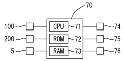
- FIG. 2 is a block diagram showing a schematic configuration of a control system of the ultrasonic tonometer 1.
- FIG. 1 is a perspective view of an ultrasonic actuator 10 according to an embodiment of the present invention. 2 is a cross-sectional view of the ultrasonic actuator 10 taken along a plane including the axis O.
- FIG. FIG. 7 is an enlarged cross-sectional view of a region R in FIG. 6 .
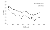
- 1 is a graph showing the results of a comparison test.
- the ultrasonic tonometer 1 includes an ultrasonic actuator 10 that emits ultrasonic waves, and measures the intraocular pressure of the subject's eye E in a non-contact manner using ultrasonic waves emitted by the ultrasonic actuator 10.
- the ultrasonic tonometer 1 can measure the intraocular pressure of the subject's eye E by optically or acoustically detecting changes in the shape or vibration of the subject's eye E caused by irradiating the subject's eye E with ultrasonic waves.
- the ultrasonic tonometer 1 may continuously irradiate the cornea of the subject's eye E with pulse waves or burst waves, and measure the intraocular pressure of the subject's eye E based on ultrasonic output information when the cornea is deformed into a predetermined state (e.g., applanation state or flattened state, etc.).
- the ultrasonic output information may be, for example, at least one of the sound pressure, acoustic radiation pressure, irradiation time (e.g., the time elapsed after a trigger signal that starts the irradiation of ultrasonic waves is input), and frequency of the ultrasonic waves.
- ultrasonic sound pressure When deforming the cornea of the subject's eye E, for example, ultrasonic sound pressure, acoustic radiation pressure, or acoustic streaming may be used. Furthermore, the ultrasonic tonometer 1 may measure the intraocular pressure of the subject's eye E based on an ultrasonic signal received in association with irradiation of the subject's eye E with ultrasonic waves. In this case, at least one of the amplitude and frequency of the ultrasonic waves may be used as the ultrasonic signal.
- the ultrasonic actuator 10 may also be used in ophthalmic devices other than the ultrasonic tonometer 1.
- the schematic configuration of the ultrasonic tonometer 1 will be described with reference to FIG. 1.
- the front-rear direction of the device is the Z direction
- the left-right direction of the device is the X direction
- the up-down direction of the device is the Y direction.
- the ultrasonic tonometer 1 of this embodiment includes a base 2, a housing 3, a face support unit 4, and a drive unit 5.
- the base 2 supports the entire device, including the housing 3 of the ultrasonic tonometer 1.
- the housing 3 is provided with an irradiation unit 100 and an optical system 200, which will be described later.
- the housing 3 is also provided with a display unit 75 that displays various images, and an operation unit 76 (for example, a touch panel provided on the display unit 75) for the examiner to input various instructions to the ultrasonic tonometer 1.
- the face support unit 4 supports the face of the subject.
- the face support unit 4 of this embodiment is installed on the base 2. However, the face support unit 4 may be installed at a location other than the base 2.
- the drive unit 5 changes the relative position between the subject's eye E supported by the face support unit 4 and the housing 3.
- the drive unit 5 in this embodiment changes the relative position between the subject's eye E and the housing 3 by moving the housing 3 relative to the base 2 .
- FIG. 2 is a plan view showing a schematic configuration inside the housing of the ultrasonic tonometer 1 of this embodiment.
- FIG. 3 is a diagram showing a schematic configuration of the irradiation unit 100 when viewed from the side of the subject's eye E. As shown in FIG. 2, the irradiation unit 100 is disposed in front of the subject's eye E and irradiates ultrasonic waves to the subject's eye E (the cornea of the subject's eye E in this embodiment). As shown in FIG.
- a plurality of ultrasonic actuators 10 (10A, 10B, 10C, 10D, 10E, 10F) are disposed in the irradiation unit 100 of this embodiment. That is, the irradiation unit 100 of this embodiment can also be expressed as a parametric speaker.
- the ultrasonic tonometer 1 of this embodiment applanates the cornea of the subject's eye E by irradiating ultrasonic waves generated by the plurality of ultrasonic actuators 10 to the cornea. As a result, the cornea is easily applanated appropriately by the plurality of ultrasonic actuators 10, and intraocular pressure measurement by ultrasonic waves is easily performed more appropriately.
- the ultrasonic actuator 10 will be described in detail later.
- the ultrasonic actuators 10 are held by the holding unit 101 with the axial tip side (the side where the ultrasonic waves are irradiated) facing the test eye side.
- the shape of the test eye E side of the holding unit 101 in this embodiment is a partial sphere.
- the ultrasonic actuators 10 are arranged on a sphere by being held by the holding unit 101. As a result, the sound axes of the ultrasonic actuators 10 intersect at one point, so that the ultrasonic waves tend to converge at the point where the sound axes intersect.
- the ultrasonic actuators 10 do not necessarily have to be arranged on a sphere, and may be arranged on a curved surface such as an elliptical sphere, or may be arranged on a plane.
- the drive waveforms of the ultrasonic actuators 10 it is also possible to control the phase of the ultrasonic waves irradiated to the test eye E.
- the phase of the ultrasonic waves irradiated to the test eye E at least one of the following may be performed: adjustment of the focal position, and control of the increase and decrease of the ultrasonic output.
- ultrasonic actuators 10 (10A to 10F) are used in the irradiation unit 100 of this embodiment, but it goes without saying that the number of ultrasonic actuators 10 used is not limited to six.
- One ultrasonic actuator 10 may be used alone in an ophthalmic device such as an ultrasonic tonometer.
- the holding portion 101 is formed with an opening 102 for passing the optical axis of the optical system 200.
- an opening 102 for passing the optical axis O1 of the observation system (imaging optical system) 220 described later is provided in the center of the holding portion 101.
- the optical axis O1 of the observation system 220 is positioned in the opening 102 of the holding portion 101.
- a first hole 103 through which the light projection optical axis O3 of the deformation detection system 260 (or the Z alignment detection system 280) passes is provided on one of the left and right sides of the holding part 101, and a second hole 104 through which the light reception optical axis O4 of the deformation detection system 260 (or the Z alignment detection system 280) passes is provided on the other side.
- the opening 102 is provided with a translucent member (e.g., a transparent plate or lens) 102A that transmits light while preventing foreign matter from entering the ultrasonic actuator 10.
- the first hole 103 is provided with a translucent member 103A
- the second hole 104 is provided with a translucent member 104A.
- the ultrasonic actuators 10A to 10F are held by the holding unit 101 so as to surround the periphery of the opening 102 through which the optical axis O1 of the observation system 220 passes.
- the ultrasonic actuators 10A to 10F are arranged so that the sound source area (the total area of the ultrasonic irradiation surface of each ultrasonic actuator 10A to 10F) is vertically symmetrical in each of the upper and lower regions when the holding unit 101 is divided by a horizontal plane H including the optical axis O1.
- the ultrasonic actuators 10A to 10F are arranged so that the sound source area is horizontally symmetrical in each of the left and right regions when the holding unit 101 is divided by a vertical plane V including the optical axis O1.
- the sound axis L1 of the ultrasonic waves can be prevented from deflecting relative to the optical axis O1, making it easier for the ultrasonic waves to be more appropriately irradiated to the subject's eye E.
- the sound axis is the central axis of the ultrasonic waves irradiated by the irradiation unit 100.
- the sound axis extends in the direction of ultrasonic propagation or in the direction of vibration of the irradiation unit 100, and passes through the focal position where the ultrasonic waves output by the irradiation unit 100 are focused.
- the shape of the ultrasonic actuators 10A to 10F (more specifically, the inner shape of the reflecting unit 50 described later) is circular or elliptical. Therefore, corners are less likely to occur on the inner surface of the reflecting unit 50, and reductions in diffraction, etc. at the corners are less likely to occur. As a result, ultrasonic waves are more likely to be irradiated to the test eye E more appropriately.
- the shape of the ultrasonic actuators 10A and 10D is circular.
- the direction of ultrasonic irradiation by the ultrasonic actuators 10A and 10D is more likely to be stable.
- the shape of the ultrasonic actuators 10B, 10C, 10E, and 10F is elliptical according to the installation space of each ultrasonic actuator 10 in the holding unit 101.
- the degree of freedom in the arrangement of the multiple ultrasonic actuators 10A to 10F is appropriately ensured.
- the multiple ultrasonic actuators 10A to 10F are held by the holding unit 101 so that all of the multiple ultrasonic actuators 10A to 10F are within a range in which the angle with respect to the optical axis O1 is 48 degrees or less when viewed from the subject's eye E (more specifically, the corneal apex of the subject's eye E).
- the configuration of the optical system 200 in the ultrasonic tonometer 1 of this embodiment will be described with reference to Fig. 2.
- the optical system 200 is used to perform at least one of observation and measurement of the subject's eye.
- the optical system 200 of this embodiment includes an objective system 210, an observation system 220, a fixation target projection system 230, an illumination system 240, a deformation detection system 260, a Z-alignment detection system 280, a dichroic mirror 201, and a beam splitter 204.
- the objective system 210 is an optical system for at least one of taking in light from outside the housing 3 into the optical system 200 and irradiating light from the optical system 200 to outside the housing 3.
- the objective system 210 includes optical elements (e.g., at least one of an objective lens, a relay lens, etc.).
- the illumination system 240 includes an illumination light source 241 and illuminates the subject's eye E.
- the illumination system 240 illuminates the subject's eye E with infrared light using the illumination light source 241, which is an infrared light source.
- multiple illumination light sources 241 are positioned diagonally in front of the subject's eye E.
- the observation system 220 captures an observation image of the subject's eye E (in this embodiment, an image of the anterior part of the subject's eye E).
- the observation system 220 of this embodiment includes a light receiving lens 221 and a light receiving element 222.
- the observation system 220 of this embodiment receives a reflected light beam from the subject's eye E centered on the optical axis O1. That is, at least a portion of the light emitted from the illumination light source 241 and reflected by the subject's eye E is received by the light receiving element 222.
- the reflected light from the subject's eye E passes through the opening 102 of the irradiation unit 100, passes through the objective system 210 and the light receiving lens 221, and is received by the light receiving element 222.
- the corneal reflection bright spot of the illumination light source 241 received by the light receiving element 222 is used, for example, for alignment in the up, down, left, and right directions (XY alignment).
- the illumination system 240 and the observation system 220 function as an XY alignment detection means.
- an index projection system that projects an index for XY alignment from the optical axis O1 onto the subject's eye may be provided in addition to the illumination system 240.
- the central corneal bright spot is captured in the observation image of the observation system 220, so XY alignment may be performed based on the central corneal bright spot.
- the fixation target projection system 230 projects a fixation target onto the subject's eye E.
- the fixation target projection system 230 of this embodiment includes a target light source 231, an aperture 232, a projection lens 233, an aperture 234, etc.
- Light from the target light source 231 passes through the aperture 232, the projection lens 233, the aperture 234, etc. along the optical axis O2, and is reflected by the dichroic mirror 201.
- the dichroic mirror 201 makes the optical axis O2 of the fixation target projection system 230 coaxial with the optical axis O1.
- the light from the target light source 231 reflected by the dichroic mirror 201 passes through the objective system 210 along the optical axis O1, and is irradiated onto the subject's eye E.
- the subject fixates the target of the fixation target projection system 230, thereby stabilizing the subject's line of sight.
- the deformation detection system 260 detects deformation of the cornea of the subject's eye E.
- the deformation detection system 260 of this embodiment includes a light source 261, a light projecting lens 262, an aperture 263, a light receiving lens 264, an aperture 265, and a light receiving element 266.
- Light from the light source 261 passes through the light projecting lens 262, the aperture 263, and the first hole 103 of the holding unit 101 along the optical axis O3, and is irradiated onto the subject's eye E.
- the reflected light emitted from the light source 261 and reflected by the subject's eye E passes through the second hole 104 of the holding unit 101 along the optical axis O4, is reflected by the beam splitter 204, passes through the light receiving lens 264 and the aperture 265, and is received by the light receiving element 266.
- the deformation detection system 260 detects deformation of the cornea based on the corneal reflected light received by the light receiving element 266.
- the deformation detection system 260 may detect the deformation state of the cornea based on the magnitude of the light receiving signal of the light receiving element 266.
- the deformation detection system 260 may detect the timing when the amount of light received by the light receiving element 266 is maximum as the timing when the cornea is in an applanated state. In this case, the deformation detection system 260 is set so that the amount of light received is maximum when the cornea of the subject eye is in an applanated state.
- the deformation detection system 260 may be an anterior segment cross-sectional image capturing unit such as an OCT or Scheimpflug camera.
- the deformation detection system 260 may also detect at least one of the amount of deformation or the deformation speed of the cornea.
- the Z alignment detection system 280 detects the relative positional relationship in the Z direction between the subject's eye E and the housing 3 (i.e., the alignment state in the Z direction).
- the Z alignment detection system 280 of this embodiment includes a light receiving lens 281 and a light receiving element 282.
- the Z alignment detection system 280 of this embodiment detects the alignment state in the Z direction by detecting reflected light from the cornea of the subject's eye E.
- the Z alignment detection system 280 of this embodiment receives reflected light emitted from the light source 261 and reflected by the cornea of the subject's eye E.
- the Z alignment detection system 280 may receive a bright spot formed by the light from the light source 261 being reflected by the cornea of the subject's eye E.
- the light source 261 of the deformation detection system 260 is also used as the light source of the Z alignment detection system 280.
- the Z alignment detection system 280 may detect the alignment state based on the receiving position of the light from the light source 261 on the light receiving element 282.
- the control unit 70 is responsible for various controls in the ultrasonic tonometer 1 (e.g., control of the entire device, arithmetic processing of measured values, etc.).
- the control unit 70 may be realized, for example, by a general CPU (Central Processing Unit) 71, a ROM 72, a RAM 73, etc.
- the ROM 72 stores various programs and initial values for controlling the operation of the ultrasonic tonometer 1.
- the RAM 73 temporarily stores various information.
- the control unit 70 may be configured by one control unit or multiple control units (i.e., multiple processors).
- the control unit 70 is connected to, for example, the drive unit 5, the storage unit 74, the display unit 75, the operation unit 76, the irradiation unit 100, the optical system 200, etc.
- the ultrasonic actuator 10 (10A to 10F) of this embodiment will be described in detail with reference to FIG. 5 to FIG. 7.
- the ultrasonic actuator used in the ultrasonic tonometer 1 of this embodiment is a so-called Langevin type transducer (sometimes called a "bolt-tightened Langevin type transducer").
- the ultrasonic element 11 (11A, 11B) is compressed by two mass members (sonotrode 20 and back mass 30), so that ultrasonic waves are generated with high efficiency while mechanical and thermal energy losses are reduced.
- one ultrasonic actuator 10A out of six ultrasonic actuators 10A to 10F used in the ultrasonic tonometer 1 will be described as an example.
- the other ultrasonic actuators 10B to 10F may be completely the same as the ultrasonic actuator 10A described below, or the shapes of some members may be slightly different.
- the axis of the ultrasonic actuator 10 (which is also the axis of the sonotrode 20 of the ultrasonic actuator 10) is O.
- the ultrasonic waves are emitted toward the tip side of the axis O (the upper side in FIGS. 5 to 7).
- the ultrasonic actuator 10 of this embodiment includes ultrasonic elements 11 (11A, 11B), electrodes 12 (12A, 12B), a sonotrode 20, a back mass 30, a bolt 40, and a reflecting portion 50.
- the ultrasonic element 11 generates ultrasonic waves.
- a voltage element piezoelectric ceramic, etc.
- a magnetostrictive element may be used as the ultrasonic element 11.
- the ultrasonic element 11 of this embodiment has an annular (ring-shaped) shape.
- a plurality of (two in this embodiment) ultrasonic elements 11A, 11B are used in a stacked state.
- Electrodes 12 (12A, 12B) are connected to each of the plurality of ultrasonic elements 11A, 11B.
- the electrode 12 of this embodiment also has an annular (ring-shaped) shape.
- the electrode 12A is connected to the tip side of the ultrasonic element 11A
- the electrode 12B is connected to the tip side of the ultrasonic element 11B.
- the sonotrode 20 and back mass 40 (sometimes collectively referred to as the "mass member") sandwich the ultrasonic element 11 between them, thereby increasing the tensile strength of the ultrasonic element 11 and improving its vibration resistance. As a result, it becomes easier to generate high-output ultrasonic waves.
- a metal block or the like may be used as the mass member.
- the sonotrode (sometimes called a horn or front mass) 20 is a mass member arranged at the tip side of the ultrasonic element 11 in the axial O direction (i.e., the side of the examined eye E).
- the sonotrode 20 propagates ultrasonic waves generated by the ultrasonic element 11 into the air.
- a flexural vibration section 22 is provided at the tip side of the sonotrode 20 in the axial O direction (i.e., closer to the tip side than the sonotrode main body section 21).
- the flexural vibration section 22 flexibly vibrates in response to the ultrasonic vibration of the sonotrode 20. As a result, ultrasonic waves are more easily irradiated with a higher output than when the flexural vibration section 22 is not provided.
- the flexural vibration section 22 and the sonotrode main body section 21 are formed integrally.
- the sonotrode body 21, which has a columnar external shape (cylindrical in this embodiment) is cut out in an annular shape at a portion slightly closer to the base end than the tip in the axial O direction, and the portion remaining on the tip side of the cut-out portion is formed as the flexural vibration portion 22. Therefore, the sonotrode 20 equipped with the flexural vibration portion 22 is appropriately manufactured from a single member.
- a flange portion 24 that expands in a direction away from the axis O is provided near the rear end of the sonotrode 20 in the axial O direction.
- the flange portion 24 is used to attach the ultrasonic element 11, electrode 12, sonotrode 20, flexural vibration portion 22, back mass 30, and bolt 50 of the ultrasonic actuator 10 to the ultrasonic tonometer 1. Details will be described later, but in this embodiment, the fixing portion 60 of the reflecting portion 50 is attached to the flange portion 24, and the reflecting portion 50 is further held by the holding portion 101 (see Figures 2 and 3), thereby attaching the ultrasonic actuator 10 to the ultrasonic tonometer 1.
- a screw hole 25 is formed near the axis O of the sonotrode 20 from the rear end to the center portion in the axial O direction. A bolt 40 is screwed into the screw hole 25.
- the back mass 30 is a mass member arranged on the rear end side of the ultrasonic element 11 in the axial O direction.
- the back mass 30 sandwiches the ultrasonic element 11 between itself and the sonotrode 20.
- the back mass 30 is substantially cylindrical in shape.
- a screw hole 35 is formed near the axis O of the back mass 30, penetrating from the tip to the rear end in the axial O direction.
- the bolt 40 has a generally cylindrical or cylindrical shape.
- a helical thread is formed on the outer periphery of the bolt 40.
- the thread of the bolt 40 screws into the threaded hole 25 of the sonotrode 20 and the threaded hole 35 of the back mass 30.
- the bolt 40 screws into the threaded hole 35 of the back mass 30 and the threaded hole 25 of the sonotrode 20. Therefore, the sonotrode 20 and the back mass 30 are tightened in a direction that brings them closer to each other. As a result, the ultrasonic element 11 is tightly clamped between the sonotrode 20 and the back mass 30.
- the ultrasonic actuator 10 is equipped with an insulating member 42.
- the insulating member 42 is disposed between the inner circumferential surface of the ring-shaped ultrasonic elements 11A, 11B and electrodes 12A, 12B and the outer circumferential surface of the bolt 40, thereby preventing electric leakage to the bolt 40.
- the reflecting part 50 covers at least a part of the circumferential direction of the flexural vibration part 22 (in this embodiment, the entire circumferential direction) when the axis O is used as a reference, while forming a gap between the reflecting part 50 and the flexural vibration part 22.
- the reflecting part 50 reflects at least a part of the ultrasonic waves generated from the flexural vibration part 22, and guides the direction of irradiation of the ultrasonic waves by the ultrasonic actuator 10 to the tip side in the axial O direction.
- the ultrasonic waves generated from the flexural vibration part 22 propagate not only to the tip side of the axis O, but also in a direction away from the axis O.
- ultrasonic waves propagated from the flexural vibration part 22 in a direction other than the tip side in the axial O direction are also reflected by the reflecting part 50 and are easily guided to the tip side in the axial O direction.
- the ultrasonic waves generated by the ultrasonic actuator 10 are easily irradiated to the test eye E with high efficiency.
- aluminum or resin which has a large difference in acoustic impedance with air, is used as the material of the reflecting part 50.
- the reflecting section 50 in this embodiment covers the entire circumferential circumference of the flexible vibration section 22. Therefore, ultrasonic waves are easily guided to the tip side in the axial O direction around the entire circumferential circumference, which makes it easier to further improve the efficiency of ultrasonic emission to the subject's eye E. Also, in this embodiment, the gap between the flexible vibration section 22 and the reflecting section 50 is provided around the entire circumferential circumference of the flexible vibration section 22. Therefore, ultrasonic waves propagated to the rear end side of the flexible vibration section 22 are easily guided to the tip side through the gap provided around the entire circumferential circumference.
- the tip of the reflecting section 50 in the axial O direction protrudes further toward the tip side than the tip of the flexural vibration section 22 in the axial O direction.
- the inner surface of the reflecting section 50 i.e., the surface facing the axial O side, which is the inside
- the ultrasonic waves generated by the ultrasonic actuator 10 are more easily emitted to the subject's eye E with higher efficiency.
- a first inclined surface 51 is formed on at least a part of the inner peripheral surface (i.e., the surface facing the axis O) at the tip in the axial O direction, the more it approaches the tip side, the closer it is to the axis O (i.e., inward).
- the first inclined surface 51 can also be expressed as an inclined surface inclined to face the rear end side in the axial O direction.
- the first inclined surface 51 is formed at least on the inner circumferential surface on the tip side in the axial O direction from the flexural vibration section 22. As a result, the ultrasonic waves are more easily converged on the target object.
- the first inclined surface 51 is formed at least in the range from the tip position of the flexural vibration section 22 to the position of the most distal end of the inner circumferential surface of the reflecting section 50 in the axial O direction of the inner circumferential surface of the reflecting section 50.
- the first inclined surface 51 is formed in the range from the most distal end of the inner circumferential surface of the reflecting section 50 to the most distal end of the second inclined surface 52 described later.
- the first inclined surface 51 is formed at a position where the ultrasonic waves are more easily converged on the target object.
- the outer peripheral surface i.e., the surface facing away from the axis O
- the outer peripheral inclined surface 53 is formed with an outer peripheral inclined surface 53 that is inclined in a direction approaching the axis O (i.e., inward) as it approaches the tip.
- an annular space CS is formed that is surrounded by the tip side of the sonotrode main body 21, the flexural vibration part 22 provided at the tip of the sonotrode main body 21, and the inner surface of the reflecting part 50 and has a ring-shaped shape around the axis. If the reflecting part 50 is not provided, the ultrasonic waves propagating through the annular space CS often escape to the outside in a direction away from the axis O.
- a second inclined surface 52 is formed on at least a part of the inner surface of the reflecting part 50 that faces the annular space CS, which is inclined in a direction away from the axis O (i.e., outward) as it approaches the tip side.
- the second inclined surface 52 can also be expressed as an inclined surface inclined to face the tip side in the axial O direction.
- the second inclined surface 52 of this embodiment will be described in more detail.
- the base end of the second inclined surface 52 coincides with the base end of the annular space CS.
- the base end of the part of the sonotrode 20 that is annularly cut out slightly on the base side from the most distal end and the base end of the second inclined surface 52 coincide in the direction of the axis O. Therefore, the number of two surfaces adjacent to each other at an angle of 90 degrees or less is reduced near the annular space CS. Therefore, the ultrasonic waves generated by the ultrasonic actuator 10 are more easily emitted toward the subject's eye E.
- the tip end of the second inclined surface 52 is smoothly connected to the base end of the first inclined surface 51 described above. Therefore, the ultrasonic waves propagated through the annular space CS are more easily guided toward the tip side.
- the cross-sectional shape of the second inclined surface 52 formed on the inner peripheral surface of the reflecting portion 50 when viewed in a cross section including the axis O is a curved shape that is inclined in a direction away from the axis O toward the tip side.
- the ultrasonic waves propagating through the annular space CS are more likely to be reflected toward the tip side by the second inclined surface 52 more efficiently.
- the cross-sectional shape of the second inclined surface 52 when viewed in a cross section including the axis O is formed in a partial arc shape. As a result, the ultrasonic waves are efficiently reflected toward the tip side.
- the cross-sectional shape of the second inclined surface 52 may be formed in a curved shape other than a partial arc (for example, a partial elliptical arc shape, a quadratic curve shape, a sinusoidal curve shape, etc.).
- the cross-sectional shape of the second inclined surface when viewed in a cross section including the axis can also be formed in a straight line.
- a fixing portion 60 that fixes the position of the reflecting portion 50 relative to the sonotrode 20 is provided on the base end side in the axial O direction of the annular space CS.
- the sonotrode 20 and the reflecting portion 50 are spaced apart on the tip side in the axial O direction of the fixing portion 60. Therefore, ultrasonic vibration of the sonotrode 20 is more easily performed than when the reflecting portion 50 and the sonotrode 20 come into contact on the tip side of the fixing portion 60. This makes it easier for ultrasonic waves to be irradiated to the subject's eye E more appropriately.
- a configuration for fixing the position of the reflecting portion 50 relative to the sonotrode 20 will be described.
- a flange portion 24 that expands in a direction away from the axis O is provided near the rear end of the sonotrode 20 in the axial O direction.
- a fixing portion 60 that fixes the position of the reflecting portion 50 relative to the sonotrode 20 is provided on a part of the inside of the reflecting portion 50 (in this embodiment, the inside of the base end side of the reflecting portion 50).
- the fixing portion 60 provided on the reflecting portion 50 is attached to the flange portion 24 via vibration-proof members 62A and 62B, thereby fixing the position of the reflecting portion 50 relative to the sonotrode 20. Therefore, ultrasonic vibration of the sonotrode 20 is more likely to be performed appropriately than when the fixing portion 60 is attached to the sonotrode 20 (in this embodiment, the flange portion 24) without the vibration-proof members 62A and 62B.
- an annular (ring-shaped) vibration-proof member 62A is provided between the tip end surface of the flange portion 24 and the reflecting portion 50.
- a vibration-proof member 62B is provided between the rear end surface of the flange portion 24 and the fixed piece 55 of the reflecting portion 50.
- the fixed piece 55 and the vibration-proof member 62B in this embodiment are formed in an annular (ring-shaped) shape. However, it is also possible to change the shape of the fixed piece 55 and the vibration-proof member 62B.
- the vibration-proof members 62A and 62B, the reflecting portion 50, and the fixed piece 55 With the flange portion 24, the vibration-proof members 62A and 62B, the reflecting portion 50, and the fixed piece 55 assembled in the appropriate positions, the fixed piece 55 is fixed to the rear end surface of the reflecting portion 50 by the screw 65. As a result, the vibration-proof member 62A, the flange portion 24, and the vibration-proof member 62B are sandwiched between the rear end surface of the reflecting portion 50 and the tip end surface of the fixed piece 55, and the position of the reflecting portion 50 relative to the sonotrode 20 is fixed.
- the vibration-proof members 62A, 62 may be elastic materials such as rubber, or vibration-proof grease may be used.
- the fixing method shown in FIG. 7 is only one example, and the shape of each part may be changed.
- the flange portion 24 is provided on the sonotrode 20 instead of the back mass 30.
- the ultrasonic actuator 10 it is necessary to connect wiring to the electrodes 12A, 12B arranged between the sonotrode 20 and the back mass 30.
- the wiring connected to the electrodes 12A, 12B can be easily passed to the rear end side in the axial O direction. This prevents the configuration of the ultrasonic actuator 10 from becoming complicated.
- the reflecting portion 50 attached to the flange portion via a vibration-proof member is attached to a holding portion 101 (see Figures 2 and 3) that holds the ultrasonic actuator 10. Therefore, ultrasonic vibration of the sonotrode 20 is more easily performed than when at least one of the sonotrode 20 and the back mass 30 is directly attached to the holding portion 101. This makes it easier for ultrasonic waves to be irradiated to the subject's eye E more appropriately.
- the cross-sectional shape of the inner circumferential surface of the reflecting portion 50 when viewed in a cross section perpendicular to the axis O at any position in the axial direction will be described.
- the cross-sectional shape of the inner circumferential surface of the reflecting portion 50 in a cross section perpendicular to the axis O is circular or elliptical. In this case, corners are unlikely to occur on the inner circumferential surface of the reflecting portion 50, so that reductions in diffraction and the like at the corners are unlikely to occur.
- the cross-sectional shape of the inner circumferential surface of the reflecting portion 50 is circular, the irradiation direction of the ultrasonic waves guided by the reflecting portion 50 is more likely to be stable.
- the cross-sectional shape of the inner circumferential surface of the reflecting portion 50 an ellipse according to the space in which the ultrasonic actuator 10 is placed, the degree of freedom in the placement of the ultrasonic actuator 10 is more likely to be ensured.
- the ultrasonic actuator 10 may further include a protective member (e.g., a mesh-like member or a slit-like member) that covers the tip opening of the reflecting section 50 and allows ultrasonic waves to pass from the tip opening to the tip side in the axial O direction.
- a protective member e.g., a mesh-like member or a slit-like member
- the results of a comparison test to confirm the effect of using the reflecting portion 50 will be described.
- the sound pressure level was measured while changing the distance from the tip of the ultrasonic actuator in the direction along the axis O using each of the ultrasonic actuator 10 with the reflecting portion 50 of the above embodiment ("with reflecting portion” in FIG. 8) and the ultrasonic actuator with only the reflecting portion 50 removed ("without reflecting portion” in FIG. 8). All conditions were the same except for the presence or absence of the reflecting portion 50.
- the sound pressure level in the case of "with reflecting portion” was higher than the sound pressure level in the case of "without reflecting portion” regardless of the distance from the tip. From the above results, it can be confirmed that the output of the ultrasonic waves irradiated in the direction of the tip of the axis O is higher by using the reflecting portion 50.
- the technology disclosed in the above embodiment is merely an example. Therefore, it is possible to change the technology exemplified in the above embodiment.
- the fixing portion 60 of the reflecting portion 50 is attached to the flange portion 24, which is a continuous shape in the circumferential direction of the outer periphery of the mass member (sonotrode 20 in this embodiment), so that the position of the reflecting portion 50 relative to the sonotrode 20 is fixed.
- the position of the reflecting portion 50 relative to the sonotrode 20 may be fixed by forming a plurality of fixing members such as protrusions at regular intervals on the outer periphery of the mass member (at least one of the sonotrode 20 and the back mass 30) and sandwiching each fixing member in the direction of the axis O.
Landscapes
- Life Sciences & Earth Sciences (AREA)
- Health & Medical Sciences (AREA)
- Medical Informatics (AREA)
- Biophysics (AREA)
- Ophthalmology & Optometry (AREA)
- Engineering & Computer Science (AREA)
- Biomedical Technology (AREA)
- Heart & Thoracic Surgery (AREA)
- Physics & Mathematics (AREA)
- Molecular Biology (AREA)
- Surgery (AREA)
- Animal Behavior & Ethology (AREA)
- General Health & Medical Sciences (AREA)
- Public Health (AREA)
- Veterinary Medicine (AREA)
- Eye Examination Apparatus (AREA)
- Ultra Sonic Daignosis Equipment (AREA)
Priority Applications (1)
| Application Number | Priority Date | Filing Date | Title |
|---|---|---|---|
| JP2025534053A JPWO2025018326A1 (https=) | 2023-07-19 | 2024-07-16 |
Applications Claiming Priority (2)
| Application Number | Priority Date | Filing Date | Title |
|---|---|---|---|
| JP2023-117773 | 2023-07-19 | ||
| JP2023117773 | 2023-07-19 |
Publications (1)
| Publication Number | Publication Date |
|---|---|
| WO2025018326A1 true WO2025018326A1 (ja) | 2025-01-23 |
Family
ID=94281568
Family Applications (1)
| Application Number | Title | Priority Date | Filing Date |
|---|---|---|---|
| PCT/JP2024/025420 Pending WO2025018326A1 (ja) | 2023-07-19 | 2024-07-16 | 超音波眼圧計および眼科用超音波アクチュエータ |
Country Status (2)
| Country | Link |
|---|---|
| JP (1) | JPWO2025018326A1 (https=) |
| WO (1) | WO2025018326A1 (https=) |
Citations (3)
| Publication number | Priority date | Publication date | Assignee | Title |
|---|---|---|---|---|
| JP2019509111A (ja) * | 2016-03-03 | 2019-04-04 | アルマ レーザー エルティーディー.Alma Lasers Ltd. | ソノトロード |
| JP2020089510A (ja) * | 2018-12-04 | 2020-06-11 | 株式会社ニデック | 超音波眼圧計 |
| JP2021010393A (ja) * | 2019-07-03 | 2021-02-04 | 株式会社ニデック | 超音波眼圧計 |
-
2024
- 2024-07-16 WO PCT/JP2024/025420 patent/WO2025018326A1/ja active Pending
- 2024-07-16 JP JP2025534053A patent/JPWO2025018326A1/ja active Pending
Patent Citations (3)
| Publication number | Priority date | Publication date | Assignee | Title |
|---|---|---|---|---|
| JP2019509111A (ja) * | 2016-03-03 | 2019-04-04 | アルマ レーザー エルティーディー.Alma Lasers Ltd. | ソノトロード |
| JP2020089510A (ja) * | 2018-12-04 | 2020-06-11 | 株式会社ニデック | 超音波眼圧計 |
| JP2021010393A (ja) * | 2019-07-03 | 2021-02-04 | 株式会社ニデック | 超音波眼圧計 |
Also Published As
| Publication number | Publication date |
|---|---|
| JPWO2025018326A1 (https=) | 2025-01-23 |
Similar Documents
| Publication | Publication Date | Title |
|---|---|---|
| US9936865B2 (en) | Fiber scanning optical probe and medical imaging apparatus including the same | |
| JP2009268651A5 (https=) | ||
| JP7110681B2 (ja) | 非接触式超音波眼圧計 | |
| JP5397670B2 (ja) | 非接触式超音波眼圧計 | |
| JP7540558B2 (ja) | 超音波眼圧計、および、超音波アクチュエータ | |
| WO2021024764A1 (ja) | 超音波眼圧計 | |
| WO2025018326A1 (ja) | 超音波眼圧計および眼科用超音波アクチュエータ | |
| JP7210851B2 (ja) | 超音波眼圧計、および超音波アクチュエータ | |
| JP2015215405A (ja) | 医療用レーザ装置 | |
| JP7119597B2 (ja) | 超音波眼圧計 | |
| JP2010068873A (ja) | 非接触式超音波眼圧計 | |
| WO2019189272A1 (ja) | 非接触式超音波眼圧計 | |
| JP7606093B2 (ja) | 超音波眼圧計、および超音波眼圧計制御プログラム | |
| JP7706048B2 (ja) | 超音波眼圧計、および超音波眼圧計制御プログラム | |
| JP7247561B2 (ja) | 超音波眼圧計 | |
| JP7110680B2 (ja) | 非接触式超音波眼圧計 | |
| JP7259599B2 (ja) | 超音波眼圧計 | |
| JP7192272B2 (ja) | 超音波眼圧計 | |
| WO2022210016A1 (ja) | 超音波眼圧計、および超音波眼圧計制御プログラム | |
| JP5562703B2 (ja) | 非接触式超音波眼圧計 | |
| JP2021108816A (ja) | 超音波眼圧計 | |
| WO2023190572A1 (ja) | 超音波眼圧計 | |
| JP2012005602A (ja) | 超音波照射装置 | |
| WO2021024765A1 (ja) | 超音波眼圧計 | |
| JP2023149310A (ja) | 超音波治療システム、超音波検査システム、治療方法、検査方法、及びプログラム |
Legal Events
| Date | Code | Title | Description |
|---|---|---|---|
| 121 | Ep: the epo has been informed by wipo that ep was designated in this application |
Ref document number: 24843116 Country of ref document: EP Kind code of ref document: A1 |
|
| ENP | Entry into the national phase |
Ref document number: 2025534053 Country of ref document: JP Kind code of ref document: A |
|
| WWE | Wipo information: entry into national phase |
Ref document number: 2025534053 Country of ref document: JP |
|
| NENP | Non-entry into the national phase |
Ref country code: DE |