WO2025018231A1 - 駆動装置 - Google Patents
駆動装置 Download PDFInfo
- Publication number
- WO2025018231A1 WO2025018231A1 PCT/JP2024/024801 JP2024024801W WO2025018231A1 WO 2025018231 A1 WO2025018231 A1 WO 2025018231A1 JP 2024024801 W JP2024024801 W JP 2024024801W WO 2025018231 A1 WO2025018231 A1 WO 2025018231A1
- Authority
- WO
- WIPO (PCT)
- Prior art keywords
- motor
- case
- stator
- motor case
- ecu
- Prior art date
- Legal status (The legal status is an assumption and is not a legal conclusion. Google has not performed a legal analysis and makes no representation as to the accuracy of the status listed.)
- Ceased
Links
Images




Classifications
-
- H—ELECTRICITY
- H02—GENERATION; CONVERSION OR DISTRIBUTION OF ELECTRIC POWER
- H02K—DYNAMO-ELECTRIC MACHINES
- H02K5/00—Casings; Enclosures; Supports
- H02K5/04—Casings or enclosures characterised by the shape, form or construction thereof
- H02K5/10—Casings or enclosures characterised by the shape, form or construction thereof with arrangements for protection from ingress, e.g. water or fingers
Definitions
- This disclosure relates to a drive device.
- the purpose of this disclosure is to provide a drive device that can prevent water droplets and the like from entering the inside of the device.
- the drive device of the present disclosure includes a motor and a controller.
- the motor has a motor housing with a cylindrical motor case, a stator fixed to the motor housing, motor wires wound around the stator, a rotor that rotates when electricity is applied to the motor wires, and a shaft that rotates integrally with the rotor.
- the controller has a board on which electronic components related to the drive control of the motor are mounted, and a controller housing that houses the board, and is located on one side of the motor in the axial direction.
- the controller housing seals the end of the motor case on the controller side, which makes it possible to prevent water droplets and the like from entering the inside of the device.
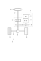
- FIG. 1 is a schematic configuration diagram of a steering system according to a first embodiment
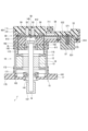
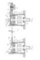
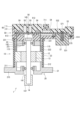
- FIG. 2 is a cross-sectional view of a drive device according to a first embodiment
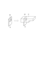
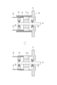
- FIG. 3 is a schematic diagram illustrating a connection between a motor case and an ECU case according to the first embodiment
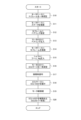
- FIG. 4 is a flowchart illustrating an assembly process of the drive device according to the first embodiment.
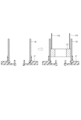
- FIG. 5 is an explanatory diagram illustrating assembly of a motor case and a stator according to the first embodiment
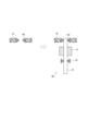
- FIG. 6 is an explanatory diagram illustrating assembly of the rotor ASSY according to the first embodiment;
- FIG. 1 is a schematic configuration diagram of a steering system according to a first embodiment
- FIG. 2 is a cross-sectional view of a drive device according to a first embodiment
- FIG. 3 is a schematic diagram illustrating a connection between a motor case and an ECU case according to the first embodiment
- FIG. 4 is a flowchart illustrating an assembly process of the drive device according
- FIG. 7 is an explanatory diagram for explaining assembly of the motor ASSY according to the first embodiment
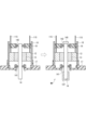
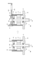
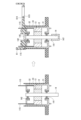
- FIG. 8 is an explanatory diagram for explaining assembly of an ECU case and an ECU-ASSY to a motor ASSY according to the first embodiment
- FIG. 9 is a cross-sectional view of a drive device according to a second embodiment
- FIG. 10 is a flowchart illustrating an assembly process of the drive device according to the second embodiment.
- FIG. 11 is an explanatory diagram illustrating the formation of a motor case according to a second embodiment
- FIG. 12 is an explanatory diagram for explaining assembly of an ECU case to a motor ASSY according to a second embodiment
- FIG. 13 is a cross-sectional view of a drive device according to a third embodiment;
- FIG. 14 is a flowchart illustrating an assembly process of the drive device according to the third embodiment.
- FIG. 15 is an explanatory diagram illustrating assembly of an inner case according to a third embodiment;
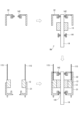
- FIG. 16 is an explanatory diagram illustrating the formation of a motor case according to a third embodiment and the assembly of an ECU case to the motor case;
- FIG. 17 is a cross-sectional view of a drive device according to the fourth embodiment.
- a drive device 1 includes a motor 10 and an ECU 50 serving as a controller, and is applied to an electric power steering device 8.
- Figure 1 shows the configuration of a steering system 90 including the electric power steering device 8.
- the steering system 90 includes a steering wheel 91, which is a steering member, a steering shaft 92, a pinion gear 96, a rack shaft 97, wheels 98, the electric power steering device 8, and the like.
- the steering wheel 91 is connected to a steering shaft 92.
- a torque sensor 94 that detects steering torque is provided on the steering shaft 92.
- a pinion gear 96 is provided at the tip of the steering shaft 92.
- the pinion gear 96 meshes with a rack shaft 97.
- a pair of wheels 98 are connected to both ends of the rack shaft 97 via tie rods or the like.
- the steering shaft 92 connected to the steering wheel 91 rotates.
- the rotational motion of the steering shaft 92 is converted into linear motion of a rack shaft 97 by a pinion gear 96.
- a pair of wheels 98 are steered to an angle that corresponds to the amount of displacement of the rack shaft 97.
- the electric power steering device 8 includes the drive unit 1 and a reduction gear 89, which is a power transmission unit that reduces the speed of the rotation of the motor 10 and transmits it to the steering shaft 92.
- the electric power steering device 8 of this embodiment is a so-called "column assist type,” and the steering shaft 92 can be said to be the driven object. It may also be a so-called "rack assist type” that transmits the rotation of the motor 10 to a rack shaft 97.
- the motor 10 is, for example, a three-phase brushless motor.
- the motor 10 outputs part or all of the torque required for steering, and is driven by power supplied from a battery (not shown), rotating the reduction gear 89 forward and reverse.
- the drive unit 1 has the ECU 50 provided on one side of the motor 10 in the axial direction, and is a so-called "mechatronically integrated" type.
- the mechatronically integrated type allows the motor 10 and ECU 50 to be efficiently arranged in a vehicle with limited mounting space.
- the axial direction and "radial direction” it will mean the axial direction and radial direction of the motor 10.
- the lower side of the paper in FIG. 2 etc. is the output end side.
- the motor 10 includes a stator 12, a rotor 13, a shaft 14, and a motor housing 15.
- the stator 12 is fixed to the motor housing 15, and the motor wire 11 is wound around the stator 12.
- the motor wire 11 is not shown in any figures other than FIG. 2.
- the rotor 13 is provided radially inside the stator 12 and is rotatable relative to the stator 12.
- the shaft 14 is fitted into the rotor 13 and rotates integrally with the rotor 13.
- the shaft 14 is rotatably supported in the motor housing 15 by bearings 141 and 142.
- the end of the shaft 14 on the ECU 50 side is exposed from the motor housing 15 to the ECU 50 side, and is provided with a sensor magnet 145.
- the end of the shaft 14 opposite the ECU 50 is the output end, which is provided with a pulley 147 and connected to the reduction gear 89.
- the motor housing 15 has a motor case 16, a front frame 17, and a rear frame 18.
- the motor case 16 is formed into a cylindrical shape from aluminum, for example.
- the motor case 16 has a front frame 17 integrally molded on the output end side, and an ECU case 61 (described below) integrally molded on the ECU 50 side.
- ECU case 61 (described below) integrally molded on the ECU 50 side.
- the front frame 17 is made of, for example, phenolic resin, and seals the end of the motor case 16 on the output end side.
- the front frame 17 is formed with a bearing holder 171, an outer wall abutment portion 172, a flange portion 175, and the like.
- the bearing holder 171 is provided with a bearing 141.
- the outer wall abutment portion 172 is formed in a cylindrical shape that extends along the outer peripheral wall of the motor case 16 toward the ECU 50 rather than toward the radially inner side. Providing the outer wall abutment portion 172 prevents water droplets and the like from entering the inside of the device from the connection point between the motor case 16 and the front frame 17.
- Multiple flange portions 175 are formed to protrude radially outward, and are attached to the gearbox by fixing members such as screws (not shown). They may also be attached to a housing other than a gearbox.
- the rear frame 18 is formed in a generally circular disk shape from, for example, phenolic resin, and is fixed to the ECU 50 side of the motor case 16.
- a bearing 142 is fixed to the rear frame 18.
- the frames 17 and 18 hold the bearings 141 and 142, and can also be considered as bearing holding members.
- the ECU 50 includes a circuit board 53, a connector 57, and an ECU housing 60.
- the circuit board 53 extends radially outward beyond the motor area, which is the area when the motor case 16 is projected in the axial direction, and is fixed to the ECU housing 60 by a fixing member 59 such as a tapping screw. Fixing members other than tapping screws may be used, and the circuit board 53 may be fixed to the ECU housing 60 by, for example, a resin rivet.
- the surface of the circuit board 53 facing the motor 10 is referred to as the motor surface 531, and the surface opposite the motor 10 is referred to as the cover surface 532.
- the lead wires 115 taken out from each phase of the motor wire 11 are formed to extend toward the ECU 50 and are electrically connected to the board 53 within the motor area.
- the lead wires 115 are soldered to the board 53, but as long as an electrical connection is established, the connection method is not limited to soldering, and may be, for example, an elastic connection by press-fit, or a solderless connection such as a mating connection using a socket connector.
- Various electronic components such as a heating element 54, a capacitor 55, and a rotation angle sensor 56 are mounted on the substrate 53.
- the heating element 54 and the capacitor 55 are mounted on the cover surface 532 of the substrate 53.
- the heating element 54 includes a switching element that constitutes an inverter that switches the current supply to the motor wires 11, a motor relay, a power relay, etc.
- the rotation angle sensor 56 is mounted on the motor surface 531 at a location facing the sensor magnet 145, and detects the rotation of the motor 10 by detecting the rotating magnetic field of the sensor magnet 145. Note that the rotation angle sensor 56 is not shown in the explanation of assembly, etc.
- the connector 57 is provided on the motor surface 531 side of the substrate 53 outside the motor area, and a connector terminal 571 is connected to the substrate 53.
- a flange 575 is formed on the end of the connector 57 on the substrate 53 side, extending from the main body toward the outer periphery.
- the flange 575 is formed in an L-shape in cross section, with the tip protruding toward the opposite side to the substrate 53.
- the ECU housing 60 has an ECU case 61 and an ECU cover 71, and is formed so that part of the radial direction extends to the outside of the motor area.
- the ECU case 61 is formed, for example, from epoxy resin into a generally bottomed cylindrical shape that opens on the side opposite the motor 10, and is molded integrally with the motor case 16, sealing the end of the motor case 16 on the ECU 50 side.
- the motor case 16 is formed with a sealing hole 162 that penetrates in the plate thickness direction.
- a plurality of sealing holes 162 are formed spaced apart in the circumferential direction at the location that is molded integrally with the ECU case 61.
- the ECU case 61 is formed by sandwiching the radially inner and outer sides at the end of the motor case 16 on the ECU 50 side.
- the resin of the ECU case 61 penetrates into the sealing hole 162, thereby improving the joining strength.
- multiple sealing holes 163 penetrating in the plate thickness direction are formed at intervals in the circumferential direction at the locations of the motor case 16 that are integrally molded with the front frame 17.
- the resin of the front frame 17 penetrates into the sealing holes 163, thereby improving the joining strength.
- the ECU case 61 is formed with an outer wall abutment portion 611, a through hole 612, a board holding portion 613, a connector mounting portion 614, and a connector insertion hole 615 (see FIG. 8).
- the outer wall abutment portion 611 is formed in a cylindrical shape that extends along the outer peripheral wall of the motor case 16 and toward the output end side from the radially inner side. Providing the outer wall abutment portion 611 prevents water droplets and the like from entering the inside of the device from the connection point between the motor case 16 and the ECU case 61. Note that the outer wall abutment portion 611 may not be provided, and the axial length of the radially outer part of the motor case 16 at the connection point between the motor case 16 and the ECU case 61 may be less than or equal to the axial length of the radially inner part. The same applies to the outer wall abutment portion 172 of the front frame 17. Also, the outer wall abutment portion 611 has been omitted from illustrations other than FIG. 2.
- the through hole 612 is provided in the axial direction at a position corresponding to the shaft 14, and a sensor magnet 145 is disposed inside.
- the board holding portion 613 is formed in the motor area, and the board 53 is fixed by a fixing member 59.
- the connector 57 is attached to the connector attachment portion 614 with adhesive or the like.
- the main body of the connector 57 is inserted into the connector insertion hole 615 with the opening exposed to the outside, and the flange portion 575 is inserted into the connector attachment portion 614 to which adhesive or the like has been applied, thereby attaching the connector 57 to the ECU case 61.
- the ECU cover 71 is formed, for example, from epoxy resin, and is provided on the cover surface 532 side of the substrate 53.
- the ECU cover 71 is molded integrally with the ECU case 61, and resin-seals the substrate 53 and the heating element 54 and capacitor 55 mounted on the cover surface 532 side of the substrate 53.
- the ECU cover 71 has heat dissipation fins 711 formed in the element mounting area, which is the axial projection of the area where the heating element 54 is mounted.
- step S10 The assembly process of the drive unit 1 of this embodiment will be described with reference to the flowchart in FIG. 4 and FIGS. 5 to 8.
- step S10 the “step” such as step S10 will be omitted and simply referred to as the symbol "S.”
- the front frame 17 is integrally molded with the motor case 16.
- the stator 12 is shrink-fitted to the motor case 16.
- the bearing 142 is fixed to the rear frame 18 by crimping, press-fitting, or the like.
- the bearings 141 and 142 are press-fitted into the rotor ASSY in which the shaft 14 is press-fitted into the rotor 13. Note that S10, S11 and S12, S13 may be performed in reverse order, or may be performed in parallel.
- the rotor ASSY in the state shown on the right side of FIG. 6 is assembled to the motor case 16 in the state shown on the right side of FIG. 5. More specifically, the rear frame 18 is shrink-fitted to the motor case 16. The bearing 141 is inserted into the bearing holder 171 of the front frame 17. In S15, the pulley 147 is press-fitted into the end of the shaft 14 on the output end side, and the sensor magnet 145 is press-fitted into the end of the shaft 14 on the ECU 50 side.
- the motor ASSY the state in which the stator 12, front frame 17, rear frame 18, etc. are assembled to the motor case 16 is referred to as the motor ASSY.
- the ECU case 61 is resin molded integrally with the motor case 16 in the state of the motor ASSY (see the left side of FIG. 8).
- adhesive is applied to the connector mounting portion 614 of the ECU case 61.
- the ECU-ASSY with the connector 57 attached is attached to the ECU case 61 (see the right side of FIG. 8).
- the lead wires 115 are electrically connected to the board 53. If the connection between the lead wires 115 and the board 53 is a solderless connection such as a press-fit connection, the connection is completed when the ECU-ASSY is assembled to the ECU case 61 in S18, and S19 is omitted.
- the ECU-ASSY is sealed with resin, and the ECU cover 71 is formed (see Figure 2).
- the rotor ASSY is designated as "RA", the motor ASSY as "MA”, and the ECU-ASSY as "EA" for convenience.
- the heating element 54 is embedded in resin in the ECU cover 71, and heat is dissipated by air radiation through the ECU cover 71 with which the heating element 54 is in direct contact. This makes it possible to mount the heating element 54 on the cover surface 532 side or outside the motor area, improving the freedom of board design. In addition, there is no need for intervening materials such as heat dissipation gel that are required when dissipating heat to a metal heat sink.
- the ECU case 61 is molded from resin integrally with the motor case 16 by insert molding, and seals the ends of the motor case 16.
- the front frame 17 is molded from resin integrally with the motor case 16 by insert molding, and seals the ends of the motor case 16. This makes it possible to prevent water droplets, dust, etc. from entering the inside of the device with a simple configuration, without any gap corrosion.
- the ECU case 61 and front frame 17 are sealed without using any sealing material such as adhesive to connect the motor case 16, so no gaps are created due to deterioration of the sealing material over time, and waterproof performance can be maintained over time. It is preferable to use materials with similar linear expansion coefficients for the ECU case 61 and front frame 17, which are molded integrally, and the motor case 16.
- the motor case 16 is made of metal
- the front frame 17 is made of resin.
- the cylindrical motor case 16 and the approximately disk-shaped front frame 17 are separated, and the end of the metal motor case 16 is resin molded to form the front frame 17, making the motor case 16 and the front frame 17 into a single molded product. This allows the components to be separated without compromising corrosion resistance.
- the front frame 17 a separate member from the motor case 16, it is relatively easy to form it, and it is also possible to use a material that has good corrosion resistance and relatively low fluidity.
- the drive unit 1 includes a motor 10 and an ECU 50.
- the motor 10 includes a motor housing 15 having a cylindrical motor case 16, a stator 12 fixed to the motor housing 15, a motor wire 11 wound around the stator 12, a rotor 13 that rotates when electricity is applied to the motor wire 11, and a shaft 14 that is rotatably supported by the motor housing 15 and rotates integrally with the rotor 13.
- the ECU 50 has a board 53 on which electronic components related to the drive control of the motor 10 are mounted, and an ECU housing 60 that houses the board 53, and is provided on one axial side of the motor 10.
- the electronic components include a heating element 54 and a capacitor 55.
- the ECU housing 60 seals the end of the motor case 16 on the ECU 50 side.
- the motor case 16 and the ECU case 61 are formed as a single molded product, and the end of the motor case 16 on the ECU 50 side is directly sealed by the ECU case 61.
- the motor housing 15 has a front frame 17 that seals the end of the motor case 16 opposite the ECU 50. This allows the front frame 17 to be formed without compromising corrosion resistance.
- the ECU housing 60 sandwiches the radially inner and outer sides of the end of the motor case 16 facing the ECU 50.
- the front frame 17 also sandwiches the radially inner and outer sides of the end of the motor case 16 opposite the ECU 50.
- the radially outer portion of the motor case 16 has a longer axial length than the radially inner portion. Also, at the connection point between the front frame 17 and the motor case 16, the radially outer portion has a longer axial length than the radially inner portion.
- the second embodiment is shown in Figures 9 to 12.
- the second to fourth embodiments differ mainly in the motor housing, so the description will be centered on the configuration related to the motor housing and will not include an explanation of the ECU 50, etc.
- the motor housing 20 of this embodiment has a front frame 21, a rear frame 22, and a motor case 23.
- the front frame 21 has a bearing holding portion 211, a stator abutment portion 212, and a number of flange portions 215, and is formed of a metal such as an aluminum alloy, and is provided on the side of the stator 21 opposite the ECU 50.
- the bearing holder 221 holds the bearing 141.
- the stator contact portion 212 is formed in a cylindrical shape along the inner peripheral wall of the motor case 23.
- the flange portion 215 is formed to protrude radially outward and is provided so as to be attachable to the housing by a fixing member such as a screw (not shown).
- the rear frame 22 has a bearing holding portion 221 and a stator abutment portion 222, is made of a metal such as an aluminum alloy, and is provided on the ECU 50 side of the stator 12.
- the bearing 142 is fixed to the bearing holding portion 221 by press fitting or the like.
- the stator abutment portion 222 is formed in a cylindrical shape along the inner peripheral wall of the motor case 23.
- the motor case 23 is formed, for example, from phenolic resin in a generally cylindrical shape.
- the motor case 23 is integrally molded with the sides of the stator 12, the front frame 21, and the rear frame 22.
- a sealing hole 231 that penetrates in the plate thickness direction is formed at the location of the motor case 23 where it is connected to the ECU case 61.
- the resin of the ECU case 61 penetrates the sealing hole 231, improving the reliability of the connection.
- Steps S30 and S31 are similar to steps S12 and S13 in FIG. 4, although the material and shape of the rear frame 22 are different from those of the first embodiment.
- the front frame 21, stator 12, and rotor ASSY are stacked.
- the front frame 21, stator 12, and rear frame 22 are stacked in this order from the output end side, and the stator abutment portion 212 of the front frame 21 and the stator abutment portion 222 of the rear frame 22 abut against the stator 12. This determines the axial position.
- stator 12, front frame 21, and rear frame 22 are resin-sealed together in the motor case 23.
- This increases the fixing force between the parts. It also reduces the thickness required to ensure the fixing strength, which contributes to reducing the weight of the drive unit 1.
- the motor case 23 is formed from resin.
- the motor housing 20 has a front frame 21 provided on one axial side of the stator 12, and a rear frame 22 provided on the other axial side of the stator 12.
- the motor case 23 is formed radially outward of the front frame 21, stator 12, and rear frame 22 stacked in the axial direction. This allows the front frame 21, stator 12, and rear frame 22 to be more firmly connected to the motor case 23, improving the reliability of the connections between the members. It also provides the same effects as the above embodiment.
- a motor housing 30 in this embodiment has a front inner case 31, a rear inner case 32, and a motor case 33.
- the front inner case 31 has a bearing holding portion 311 and a stator holding portion 312, and is formed from, for example, an aluminum alloy into a generally cylindrical shape with a bottom that opens toward the ECU 50.
- the bearing holding portion 311 holds the bearing 141.
- the stator holding portion 312 is formed into a cylindrical shape, and the end on the ECU 50 side is provided between the stator 12 and the motor case 33.
- the rear inner case 32 has a bearing holding portion 321 and a stator holding portion 322, and is formed from, for example, an aluminum alloy into a generally cylindrical shape with a bottom that opens on the side opposite the ECU 50.
- the bearing 142 is fixed to the bearing holding portion 321.
- the stator holding portion 322 is formed into a cylindrical shape. The end of the stator holding portion 322 opposite the ECU 50 is provided between the stator 12 and the motor case 33, and its tip surface abuts against the front inner case 31.
- the motor case 33 is formed in a generally cylindrical shape from, for example, phenolic resin.
- the motor case 33 is formed by integrally molding the sides of the inner cases 31, 32. Sealing holes 331 that penetrate in the plate thickness direction are formed at the locations of the motor case 33 where it is connected to the ECU case 61. The resin of the ECU case 61 penetrates the sealing holes 331, improving the reliability of the connection.
- the motor case 33 is formed with a number of flanges 335 that protrude radially outward and are used for mounting to a housing with fixing members such as screws (not shown).
- the stator 12 is shrink-fitted into the front inner case 31 so that the bearing holder 311 is on the opposite side to the side from which the lead wires 115 of the stator 12 are taken out.
- the front inner case 31 and the stator 12 may be fixed by a method other than shrink-fitting. The same applies to the fixing of the rear inner case 32 and the stator 12.
- the bearing 142 is press-fitted into the rear inner case 32, and in S42, the bearings 141, 142 are press-fitted into the rotor ASSY.
- the rear inner case 32 is placed over the stator 12 and shrink-fitted so that the open side faces the front inner case 31.
- the abutment position of the inner cases 31, 32 need only be such that the stator 12 can be shrink-fitted to both, and it does not matter if it is offset from the center position in the axial direction of the stator 12.
- the front inner case 31 and the rear inner case 32 are molded integrally with resin to form the motor case 33.
- the processing from S15 onwards is the same as in the first embodiment, with a pulley 147 being press-fitted into the output end of the shaft 14 and a sensor magnet 145 being press-fitted into the ECU 50 end of the shaft 14.
- the ECU case 61 is molded integrally with the motor case 33 with resin.
- the assembly on the ECU side is the same as in the above embodiment, so a description will be omitted.
- the stator 12 is fixed to the inner cases 31 and 32, and the outside is sealed with resin, which makes it possible to prevent water droplets and the like from entering the inside of the device without using sealing materials. It also makes it possible to improve the reliability of corrosion resistance.
- the motor housing 30 has a front inner case 31 that is fixed to the radial outside of the stator 12 and extends to one axial side of the stator 12, and a rear inner case 32 that is fixed to the radial outside of the stator 12 and extends to the other axial side of the stator 12.
- the motor case 33 is formed radially outside the front inner case 31 and the rear inner case 32. This makes it possible to form the motor case 33 relatively easily. It also provides the same effects as the above embodiment.
- a motor housing 35 in this embodiment has a front inner case 36, a front frame 37, a rear inner case 32, and a motor case 33.
- a front frame 37 having a bearing holding portion 371 that holds a bearing 141 is formed separately from the front inner case 36.
- the front frame 37 is fixed to the front inner case 36 by shrink fitting, press fitting, or the like. The subsequent assembly process is the same as that in the third embodiment.
- the front inner case 36 can be formed by press working, improving productivity.
- the same effects as the above embodiment are achieved.
- the front frame 17 corresponds to the "frame”
- the front frame 21 corresponds to the "first frame”
- the rear frame 22 corresponds to the "second frame”
- the front inner case 31 corresponds to the "first inner case”
- the rear inner case 32 corresponds to the "second inner case”
- the ECU 50 corresponds to the "controller”
- the ECU housing 60 corresponds to the "controller housing”.
- the controller housing may be made of a material other than epoxy resin.
- the motor housing may be made of a material other than phenol resin.
- the rear frame may be made of a metal with good thermal conductivity, such as an aluminum alloy.
- the motor case may be made of resin. That is, it may be "the drive device according to any one of aspects 1 to 6, in which the motor case is made of resin.”
- the motor case is formed such that the front frame and the motor case are integrally molded as separate members.
- the motor case may be formed as a cylinder with a bottom that opens to the ECU side, and the motor case and the front frame may be formed as a single member.
- the motor case is formed as a cylinder with a bottom, it is still included in the concept of a "cylindrical motor case.”
- a sealing hole is formed in the motor case, and the motor case is molded integrally with the controller housing sandwiching the radially inner and outer sides.
- the motor case and the ECU housing are molded integrally, they do not have to be sandwiched between the radially inner and outer sides.
- the sealing hole may be omitted. The same applies to the connection points between the motor case and the front frame.
- heat dissipation ribs are provided in the axial projection area of the heat generating component.
- the heat dissipation ribs may be omitted, or a separate structure for heat dissipation (for example, a metal plate with good thermal conductivity or a flow path portion through which a cooling fluid can flow) may be provided.
- the connector is provided on the motor side of the board, with its opening facing the output end in the axial direction.
- the connector may be provided on the cover side of the board, or the opening may face in a different direction.
- multiple connectors may be provided.
- the element arrangement on the board may be different from that of the above embodiment. Furthermore, as long as heat dissipation from the electronic components can be ensured, the electronic components do not need to be embedded in the controller housing.
- the controller is formed to extend radially outward beyond the motor area. In other embodiments, the controller may be provided within the motor area.
- the drive device is applied to an electric power steering device. In other embodiments, the drive device may be applied to an in-vehicle device other than an electric power steering device, or may be applied to a device other than an in-vehicle device.
Landscapes
- Engineering & Computer Science (AREA)
- Power Engineering (AREA)
- Motor Or Generator Frames (AREA)
Priority Applications (1)
| Application Number | Priority Date | Filing Date | Title |
|---|---|---|---|
| CN202480047154.8A CN121532933A (zh) | 2023-07-18 | 2024-07-09 | 驱动装置 |
Applications Claiming Priority (2)
| Application Number | Priority Date | Filing Date | Title |
|---|---|---|---|
| JP2023-116748 | 2023-07-18 | ||
| JP2023116748A JP2025014289A (ja) | 2023-07-18 | 2023-07-18 | 駆動装置 |
Publications (1)
| Publication Number | Publication Date |
|---|---|
| WO2025018231A1 true WO2025018231A1 (ja) | 2025-01-23 |
Family
ID=94282048
Family Applications (1)
| Application Number | Title | Priority Date | Filing Date |
|---|---|---|---|
| PCT/JP2024/024801 Ceased WO2025018231A1 (ja) | 2023-07-18 | 2024-07-09 | 駆動装置 |
Country Status (3)
| Country | Link |
|---|---|
| JP (1) | JP2025014289A (cg-RX-API-DMAC7.html) |
| CN (1) | CN121532933A (cg-RX-API-DMAC7.html) |
| WO (1) | WO2025018231A1 (cg-RX-API-DMAC7.html) |
Citations (3)
| Publication number | Priority date | Publication date | Assignee | Title |
|---|---|---|---|---|
| JPH11146592A (ja) * | 1997-11-04 | 1999-05-28 | Matsushita Electric Ind Co Ltd | 回転モータユニット |
| JP2014075866A (ja) * | 2012-10-03 | 2014-04-24 | Mitsubishi Electric Corp | 電動パワーステアリング装置 |
| JP2022175335A (ja) * | 2021-05-13 | 2022-11-25 | トヨタ自動車株式会社 | インホイールモータの冷却装置 |
-
2023
- 2023-07-18 JP JP2023116748A patent/JP2025014289A/ja active Pending
-
2024
- 2024-07-09 CN CN202480047154.8A patent/CN121532933A/zh active Pending
- 2024-07-09 WO PCT/JP2024/024801 patent/WO2025018231A1/ja not_active Ceased
Patent Citations (3)
| Publication number | Priority date | Publication date | Assignee | Title |
|---|---|---|---|---|
| JPH11146592A (ja) * | 1997-11-04 | 1999-05-28 | Matsushita Electric Ind Co Ltd | 回転モータユニット |
| JP2014075866A (ja) * | 2012-10-03 | 2014-04-24 | Mitsubishi Electric Corp | 電動パワーステアリング装置 |
| JP2022175335A (ja) * | 2021-05-13 | 2022-11-25 | トヨタ自動車株式会社 | インホイールモータの冷却装置 |
Also Published As
| Publication number | Publication date |
|---|---|
| JP2025014289A (ja) | 2025-01-30 |
| CN121532933A (zh) | 2026-02-13 |
Similar Documents
| Publication | Publication Date | Title |
|---|---|---|
| JP6425085B2 (ja) | 回転電機及びその製造方法 | |
| JP5634610B2 (ja) | 電動式駆動装置 | |
| CN110800196B (zh) | 电动驱动装置及电动动力转向装置 | |
| CN111934511B (zh) | 旋转电机 | |
| JP5748917B2 (ja) | 電動式駆動装置および電動式駆動装置の製造方法 | |
| US10211706B2 (en) | Rotating electrical machine | |
| CN101557141B (zh) | 电动动力转向装置用电动机及电动动力转向装置 | |
| CN111264021B (zh) | 电动驱动装置以及电动助力转向装置 | |
| CN107852072A (zh) | 逆变器一体型马达 | |
| CN113169633A (zh) | 电动驱动装置及电动助力转向装置 | |
| WO2015125234A1 (ja) | モータ駆動装置 | |
| CN113169627A (zh) | 电动驱动装置 | |
| WO2018163951A1 (ja) | 駆動装置 | |
| JP4981939B2 (ja) | 電動式駆動装置および電動式パワーステアリング装置 | |
| JP2020114044A (ja) | 駆動装置、および、これを用いた電動パワーステアリング装置 | |
| JP2025014289A (ja) | 駆動装置 | |
| US20260142523A1 (en) | Drive device | |
| JP7561985B2 (ja) | 電動機制御装置 | |
| CN111727545B (zh) | 电子控制装置以及电动驱动装置 | |
| JP2025114252A (ja) | 駆動装置 | |
| WO2026042787A1 (ja) | 電子装置 | |
| JP7296205B2 (ja) | 配線基板、及び電動駆動装置 | |
| WO2026042790A1 (ja) | 電子装置 |
Legal Events
| Date | Code | Title | Description |
|---|---|---|---|
| 121 | Ep: the epo has been informed by wipo that ep was designated in this application |
Ref document number: 24843023 Country of ref document: EP Kind code of ref document: A1 |
|
| NENP | Non-entry into the national phase |
Ref country code: DE |
|
| 122 | Ep: pct application non-entry in european phase |
Ref document number: 24843023 Country of ref document: EP Kind code of ref document: A1 |