WO2025018179A1 - 逆入力遮断クラッチおよびその組立方法 - Google Patents
逆入力遮断クラッチおよびその組立方法 Download PDFInfo
- Publication number
- WO2025018179A1 WO2025018179A1 PCT/JP2024/024406 JP2024024406W WO2025018179A1 WO 2025018179 A1 WO2025018179 A1 WO 2025018179A1 JP 2024024406 W JP2024024406 W JP 2024024406W WO 2025018179 A1 WO2025018179 A1 WO 2025018179A1
- Authority
- WO
- WIPO (PCT)
- Prior art keywords
- input
- axial
- engaging
- output
- reverse input
- Prior art date
- Legal status (The legal status is an assumption and is not a legal conclusion. Google has not performed a legal analysis and makes no representation as to the accuracy of the status listed.)
- Pending
Links
Images














Classifications
-
- F—MECHANICAL ENGINEERING; LIGHTING; HEATING; WEAPONS; BLASTING
- F16—ENGINEERING ELEMENTS AND UNITS; GENERAL MEASURES FOR PRODUCING AND MAINTAINING EFFECTIVE FUNCTIONING OF MACHINES OR INSTALLATIONS; THERMAL INSULATION IN GENERAL
- F16D—COUPLINGS FOR TRANSMITTING ROTATION; CLUTCHES; BRAKES
- F16D41/00—Freewheels or freewheel clutches
- F16D41/06—Freewheels or freewheel clutches with intermediate wedging coupling members between an inner and an outer surface
-
- F—MECHANICAL ENGINEERING; LIGHTING; HEATING; WEAPONS; BLASTING
- F16—ENGINEERING ELEMENTS AND UNITS; GENERAL MEASURES FOR PRODUCING AND MAINTAINING EFFECTIVE FUNCTIONING OF MACHINES OR INSTALLATIONS; THERMAL INSULATION IN GENERAL
- F16D—COUPLINGS FOR TRANSMITTING ROTATION; CLUTCHES; BRAKES
- F16D43/00—Automatic clutches
- F16D43/02—Automatic clutches actuated entirely mechanically
Definitions
- This disclosure relates to a reverse input cutoff clutch that transmits the rotational torque input to an input member to an output member, while completely cutting off the rotational torque input inversely to the output member, either by not transmitting it to the input member or by transmitting only a portion of it to the input member and cutting off the remainder.
- a reverse input cutoff clutch has an input member that is connected to an input mechanism such as a drive source, and an output member that is connected to an output mechanism such as a reduction mechanism, and has the function of transmitting the rotational torque input to the input member to the output member, while completely cutting off the rotational torque that is reversely input to the output member, so that it is not transmitted to the input member, or by transmitting only a portion of it to the input member and cutting off the remainder.
- Reverse input cut-off clutches are broadly divided into locking and free types, depending on the difference in the mechanism that cuts off the rotational torque that is reversely input to the output member.
- a locking type reverse input cut-off clutch is equipped with a mechanism that prevents the output member from rotating when a rotational torque is reversely input to the output member.
- a free type reverse input cut-off clutch is equipped with a mechanism that causes the output member to spin freely when a rotational torque is input to the output member. The choice of whether to use a locking type reverse input cut-off clutch or a free type reverse input cut-off clutch is determined appropriately based on the application of the device into which the reverse input cut-off clutch is incorporated.
- the pressed member has a pressed surface on its inner circumferential surface.
- the input member has an input side engagement portion arranged radially inside the pressed surface and is arranged coaxially with the pressed surface.
- the output member has an output side engagement portion that is arranged radially inward of the input side engagement portion on the radial inner side of the pressed surface, and is arranged coaxially with the pressed surface.
- the engaging element has a pressing surface facing the pressed surface, an input side engaged portion that can engage with the input side engaging portion, and an output side engaged portion that can engage with the output side engaging portion, and is arranged so as to be movable in a first direction that is a direction toward or away from the pressed surface.
- the engaging element may tilt in the axial direction. If the engaging element moves radially outward while remaining tilted in the axial direction, the pressing surface and the pressed surface may come into local contact and cause biting, which may unnecessarily increase the force required to switch from the locked or semi-locked state to the unlocked or semi-unlocked state, or cause plastic deformation in the pressing surface and/or the pressed surface.
- the present disclosure aims to provide a reverse input cutoff clutch structure and manufacturing method that can restrict axial movement of an engaging element relative to an output member while minimizing the number of parts.
- the reverse input cutoff clutch according to the first aspect of the present disclosure includes a pressed member, an input member, an output member, an engaging element, and a retaining member.
- the pressed member has a pressed surface on its inner circumferential surface.
- the input member has an input side engagement portion arranged radially inside the pressed surface and is arranged coaxially with the pressed surface.
- the output member has an output side engagement portion that is positioned radially inward from the input side engagement portion and is positioned coaxially with the pressed surface.
- the engaging element has a pressing surface facing the pressed surface, an input side engaged portion that can engage with the input side engaging portion, and an output side engaged portion that can engage with the output side engaging portion, and is arranged so as to be movable in a first direction, which is the direction in which the pressing surface moves towards or away from the pressed surface.
- the retaining member has a first spacer portion, a second spacer portion, and a connection portion that connects the first spacer portion and the second spacer portion, and is attached to the output member with the engaging element positioned between the first spacer portion and the second spacer portion in the axial direction, thereby restricting axial movement of the engaging element relative to the output member.
- the input side engaging portion engages with the input side engaged portion, and the engaging element moves in the first direction away from the pressed surface, engaging the output side engaged portion with the output side engaging portion, thereby transmitting the rotational torque input to the input member to the output member.
- the output side engaging portion engages with the output side engaged portion, and the pressing surface is pressed against the pressed surface, causing frictional engagement of the pressing surface with the pressed surface.
- the output member has an output shaft portion protruding from a center portion of an end surface on one axial side of the output side engagement portion toward the one axial side, and a small diameter shaft portion protruding from a center portion of an end surface on one axial side of the output side engagement portion toward the one axial side
- the first spacer portion has a first through hole through which the output side engagement portion and/or the small diameter shaft portion is inserted
- the second spacer portion has a second through hole through which the output side engagement portion is inserted.
- the retaining member has a locking protrusion protruding from an outer circumferential surface of the output side engaging portion or a surface facing an outer circumferential surface of the small diameter shaft portion,
- the output side engagement portion or the small diameter shaft portion has a locking groove in which the locking protrusion is engaged, at the same axial position on the outer circumferential surface as the locking protrusion.
- the side surface on the other axial direction of the locking protrusion has an inclined surface portion that is inclined in a direction toward the one axial direction as it approaches the tip end of the protruding direction of the locking protrusion.
- the side surface on one axial side of the locking protrusion is formed by a plane perpendicular to the axial direction of the pressed surface.
- the locking protrusions are provided at multiple locations spaced apart in the circumferential direction in the reverse input cutoff clutch according to any one of the third to fifth aspects of the present disclosure.
- the locking protrusion protrudes from the inner peripheral surface of the first through hole.
- the first spacer portion has a discontinuous portion at least at one location in the circumferential direction in the reverse input cutoff clutch according to the seventh aspect of the present disclosure.
- the outer circumferential surface of the small diameter shaft portion has a small diameter portion constituting one axial side portion, a large diameter portion constituting the other axial side portion, and a step surface facing one axial side and connecting the small diameter portion and the large diameter portion, an outer diameter of the small diameter portion is equal to or smaller than a diameter of an inscribed circle of the locking protrusion, The outer diameter of the large diameter portion is larger than the diameter of the inscribed circle of the locking protrusion, The locking groove is provided in the large diameter portion.
- the input member has an input member side regulating portion that regulates the holding member from moving to one side in the axial direction relative to the output member by engaging with the first spacer portion.
- a retaining ring having a radially inner portion engaged with a portion of an outer circumferential surface of the small diameter shaft portion that is located on one axial side of the first spacer portion, The first spacer portion engages with a side surface on the other axial direction side of the radially outer portion of the retaining ring, thereby restricting movement of the retaining member toward the one axial direction side relative to the output member.
- the reverse input cutoff clutch according to the twelfth aspect of the present disclosure is a reverse input cutoff clutch according to any one of the first to eleventh aspects of the present disclosure, which includes a biasing member that elastically biases the engaging element in a direction that brings it closer to the pressed surface in the first direction.
- the engaging element is composed of two engaging elements
- the input side engagement portion is composed of two input side engagement portions
- the biasing member is composed of two compression coil springs arranged between the two engaging elements, on either side of the retaining member in a second direction perpendicular to both the axial direction of the pressed surface and the first direction.
- the axial movement of the biasing member relative to the output member is restricted by the retaining member in the reverse input cutoff clutch according to the twelfth aspect of the present disclosure.
- the biasing member is disposed between the first spacer portion and the second spacer portion in the axial direction of the pressed surface, and is configured as a leaf spring elastically sandwiched between the output side engaging portion and the engaging element in the first direction.
- connection portion of the holding member is arranged on both sides of the first spacer portion and the second spacer portion in a second direction perpendicular to both the axial direction of the pressed surface and the first direction, and is configured by two connection portions each having a holding hole extending in the first direction
- the biasing member is composed of two compression coil springs that are fitted and held in the retaining holes of the two connection portions and elastically press both side portions in the second direction of the side of the engaging element opposite the pressed surface in the first direction.
- a reverse input cutoff clutch is the reverse input cutoff clutch of the fifteenth aspect of the present disclosure, a pressing piece attached to an end of each of the two compression coil springs in the extension direction of the compression coil spring; The two compression coil springs elastically press the both side portions of the engagement element via the pressing piece.
- the outer peripheral surface of the pressure piece is fitted within the inner peripheral surface of the retaining hole so as to be able to slide in the extension direction of the retaining hole.
- a guide surface portion is provided at the opening end of the inner circumferential surface of the retaining hole, the inner diameter of which increases toward the opening side.
- the outer diameter of each of the two compression coil springs in the reverse input cutoff clutch according to the fifteenth or sixteenth embodiment of the present disclosure becomes smaller from the middle portion toward both sides in the extension direction of the compression coil spring.
- the engaging element is composed of two engaging elements
- the input side engagement portion is composed of two input side engagement portions
- the retaining hole is configured as a through hole penetrating in the first direction
- Each of the two compression coil springs is elastically compressed in the first direction between the two engagement elements.
- At least one of the two connection parts has a discontinuous part at one location in the circumferential direction of the retaining hole.
- the engaging element is composed of two engaging elements,
- the input side engaging portion is made up of two input side engaging portions.
- a method for assembling a reverse input cutoff clutch is a method for assembling a reverse input cutoff clutch of the seventeenth or nineteenth aspect of the present disclosure, the reverse input cutoff clutch including the biasing member,
- the method includes a step of combining the output member, the two engaging elements, the retaining member, and the biasing member, and using an assembly jig that engages the two engaging elements with the input side engaged portions of the two engaging elements, displacing the two engaging elements in a direction radially toward each other against the elastic biasing force of the biasing member, and then inserting the two engaging elements axially into the radially inner side of the pressed surface.
- a reverse input cutoff clutch that can restrict axial movement of an engaging element relative to an output member while minimizing the number of parts, and an assembly method thereof.
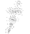
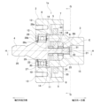
- FIG. 1 is a cross-sectional view of a reverse input cutoff clutch according to a first embodiment of the present disclosure.
- FIG. 2 is an exploded perspective view of the reverse input cutoff clutch of the first example.
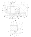
- 3A is an enlarged view of a portion A in FIG. 1
- FIG. 3B is an enlarged view of a portion B in FIG. 3A.
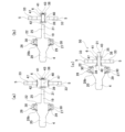
- FIG. 4 is a cross-sectional view taken along the line CC of FIG. 1 with some parts omitted.
- FIG. 5 is a cross-sectional view taken along the line DD in FIG. 1, with the holding member and the biasing member omitted.
- FIG. 6 is a view similar to FIG. 5, but showing a state in which a rotational torque is input to the input member.
- FIG. 7 is a view similar to FIG.
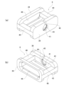
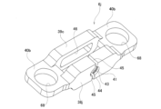
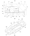
- FIG. 8(a) is a perspective view of the holding member of the first example as viewed from one axial side
- FIG. 8(b) is a perspective view of the holding member as viewed from the other axial side
- 9(a) to 9(c) are cross-sectional views showing, in order of steps, a method of assembling an assembly that constitutes a part of the reverse input cutoff clutch of the first example
- 10A to 10E are cross-sectional views showing, in order of steps, a method of assembling an assembly constituting a part of the reverse input cutoff clutch of a comparative example to the first example.
- FIG. 11 is a view corresponding to the right side of FIG.
- FIGS. 8(a) and 8(b) are views corresponding to FIGS. 8(a) and 8(b), showing a retaining member incorporated in a reverse input cutoff clutch according to a third example of an embodiment of the present disclosure.
- 13(a) and 13(b) are views corresponding to FIGS. 8(a) and 8(b) and show a retaining member incorporated in a reverse input cutoff clutch according to a fourth embodiment of the present disclosure.
- 14(a) and 14(b) are views corresponding to FIGS.
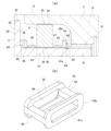
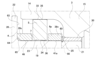
- FIG. 15(a) is a diagram corresponding to part A in FIG. 1 for a reverse input cut-off clutch according to a sixth example of an embodiment of the present disclosure
- FIG. 15(b) is an oblique view of a retaining member incorporated in the reverse input cut-off clutch, viewed from one axial side
- FIG. 16(a) is a diagram corresponding to part A in FIG. 1 for a reverse input cut-off clutch according to a seventh example of an embodiment of the present disclosure
- FIG. 16(a) is a diagram corresponding to part A in FIG. 1 for a reverse input cut-off clutch according to a seventh example of an embodiment of the present disclosure
- FIG. 16(b) is an oblique view of a retaining member incorporated in the reverse input cut-off clutch, as viewed from one axial side.
- FIG. 17(a) is a diagram corresponding to part A in FIG. 1 for a reverse input cut-off clutch according to an eighth example of an embodiment of the present disclosure
- FIG. 17(b) is an oblique view of a retaining member incorporated in the reverse input cut-off clutch, as viewed from one axial side.
- Figure 18(a) is an oblique view of a retaining member incorporated in a reverse input cut-off clutch of a ninth example of an embodiment of the present disclosure, viewed from one axial side
- Figure 18(b) is a cross-sectional view of the retaining member
- Figure 18(c) is a view of the retaining member viewed from the right of Figure 18(b).
- FIG. 19 is an exploded perspective view of a reverse input cutoff clutch according to a tenth example of an embodiment of the present disclosure.
- FIG. 20 is a diagram corresponding to FIG. 4 and showing a reverse input cutoff clutch according to the tenth example.
- FIG. 21(a) is a diagram corresponding to part A in Figure 1 for the reverse input cut-off clutch of the tenth example
- Figure 21(b) is an oblique view of a retaining member incorporated in the reverse input cut-off clutch, viewed from one axial side.
- FIG. 22 is a cross-sectional view of a reverse input cutoff clutch according to an eleventh example of an embodiment of the present disclosure.
- FIG. 23 is an exploded perspective view of the reverse input cutoff clutch of the eleventh example.
- 24(a) is an enlarged view of a portion E in FIG. 22, and
- FIG. 24(b) is an enlarged view of a portion F in FIG. 24(a).
- FIG. 25 is a cross-sectional view taken along line GG of FIG.
- FIG. 26(a) is a perspective view of a retaining member of an eleventh example, as viewed from one axial side
- FIG. 26(b) is a perspective view of a first spacer portion constituting the retaining member, as viewed from the other axial side
- FIG. 27 is a view corresponding to the right side of the lower half of FIG. 3( a ) of a reverse input cutoff clutch according to a twelfth example of an embodiment of the present disclosure.
- FIG. 28 corresponds to FIG. 26( a ) and shows a holding member incorporated in a reverse input cutoff clutch according to a thirteenth example of an embodiment of the present disclosure.
- FIG. 29 is a view corresponding to FIG.
- FIG. 26( a ) and illustrating a holding member incorporated in a reverse input cutoff clutch according to a fourteenth example of an embodiment of the present disclosure.
- FIG. 30 is a view corresponding to FIG. 26( a ) and illustrating a holding member incorporated in a reverse input cutoff clutch according to a fifteenth example of an embodiment of the present disclosure.
- FIG. 31 is a view corresponding to FIG. 26( a ) and illustrating a holding member incorporated in a reverse input cutoff clutch according to a sixteenth example of an embodiment of the present disclosure.
- FIG. 32 corresponds to FIG. 26( a ) and shows a retaining member incorporated in a reverse input cutoff clutch according to a seventeenth example of an embodiment of the present disclosure.
- Figure 33(a) is a diagram corresponding to part E in Figure 22 for a reverse input cut-off clutch of an 18th example of an embodiment of the present disclosure
- Figure 33(b) is a diagram corresponding to Figure 26(a) for a retaining member incorporated into the reverse input cut-off clutch
- FIG. 34 is a view corresponding to part E in FIG. 22, showing a reverse input cutoff clutch according to a nineteenth example of an embodiment of the present disclosure
- Figure 35(a) is a diagram corresponding to part E in Figure 22 for a reverse input cut-off clutch in a twentieth example of an embodiment of the present disclosure
- Figure 35(b) is a diagram corresponding to Figure 26(a) for a retaining member incorporated into the reverse input cut-off clutch.
- Figure 36(a) is a view corresponding to the HH cross section of Figure 22 for a reverse input cut-off clutch of a 21st example of an embodiment of the present disclosure
- Figure 36(b) is an enlarged view of part I of Figure 36(a).
- FIG. 37 is a perspective view of a portion of the output member and a retaining member of a reverse input cut-off clutch according to a twenty-first example of an embodiment of the present disclosure.
- Figures 38(a) and 38(b) are cross-sectional views corresponding to portion J in Figure 25 for a reverse input cut-off clutch of a 22nd example embodiment of the present disclosure, and specifically, Figure 38(a) shows an unlocked state in which the engaging element has moved to the radially innermost position, and Figure 38(b) shows a locked or semi-locked state in which the engaging element has moved to the radially outermost position.
- FIG. 39 is a cross-sectional view of a main portion for explaining a problem that can be prevented by the structure of the 22nd example.
- FIG. 40 is a cross-sectional view of a reverse input cutoff clutch according to a twenty-third example of an embodiment of the present disclosure, the cross-sectional view corresponding to the portion J in FIG.
- FIG. 41 is a cross-sectional view of a reverse input cutoff clutch according to a twenty-fourth example of an embodiment of the present disclosure, corresponding to a portion J in FIG. 25 , with some parts omitted.
- FIG. 1 A first example of an embodiment of the present disclosure will be described with reference to FIGS. 1 to 10.
- FIG. 1 A first example of an embodiment of the present disclosure will be described with reference to FIGS. 1 to 10.
- the axial, radial, and circumferential directions refer to the reverse input cutoff clutch 1, or more specifically, the axial, radial, and circumferential directions of the pressed surface 7 of the pressed member 2 that constitutes the reverse input cutoff clutch 1.
- the axial, radial, and circumferential directions of the reverse input cutoff clutch 1 coincide with the axial, radial, and circumferential directions of the input member 3, and also coincide with the axial, radial, and circumferential directions of the output member 4.
- One axial side is the input member 3 side (right side in FIG. 1), and the other axial side is the output member 4 side (left side in FIG. 1).
- the reverse input cutoff clutch 1 of this example includes a pressed member 2, an input member 3, an output member 4, an engagement element 5, and a holding member 6.
- the reverse input cutoff clutch 1 transmits the rotational torque input to the input member 3 to the output member 4, while having a reverse input cutoff function that completely cuts off the rotational torque reversely input to the output member 4 and does not transmit it to the input member 3, or transmits only a portion of it to the input member 3 and cuts off the remainder.
- the pressed member 2 has a pressed surface 7 on its inner circumferential surface.
- the input side engaging portion 14 of the input member 3 and the output side engaging portion 19 of the output member 4 are arranged coaxially on the radial inside of the pressed surface 7, and the engaging element 5 is arranged so as to be movable towards and away from the pressed surface 7.
- the input side engaging portion 14, the output side engaging portion 19, and the engaging element 5 are rotatable on the radial inside of the pressed surface 7.
- the pressed surface 7 forms a surface that comes into contact with the pressing surface 32 of the engaging element 5 when the engaging element 5 moves in a direction approaching the pressed surface 7.
- the pressed surface 7 is annular when viewed in the axial direction, and although not limited to this, in this example, it has a cylindrical surface shape whose inner diameter does not change in the axial direction.
- the pressed member 2 is supported and fixed to a fixed portion that does not rotate even when the housing or the like is in use, and its rotation is restricted.
- the pressed member 2 is formed by the fixed portion.
- the pressed member 2 includes an output element 8 and an input element (not shown).
- the pressed member does not include an input element.
- the output element 8 has an inner peripheral surface in the shape of a stepped cylindrical surface. That is, the inner peripheral surface of the output element 8 is formed by connecting a large diameter cylindrical surface portion 9 on one axial side with a small diameter cylindrical surface portion 10 on the other axial side by a connection surface portion 11 facing one axial side. In this example, the large diameter cylindrical surface portion 9 forms the pressed surface 7.
- the output element 8 has an inward flange portion 12 that protrudes radially inward at the end portion on the other axial side of the small diameter cylindrical surface portion 10.
- the input element is fitted (spigot-fitted) to the output element 8 without rattle, and the output element 8 and the input element are positioned radially, and then the output element 8 and the input element are joined to each other with a joining member such as a bolt to form the pressed member 2.
- the pressed member 2 is supported and fixed to the fixed portion by threading a bolt inserted through a through hole provided in the fixed portion into a screw hole 13 opening on the side surface of the output element 8 on the other axial side.
- the input member 3 has an input side engaging portion 14 arranged radially inside the pressed surface 7, and is arranged coaxially with the pressed surface 7.
- the input member 3 is connected to an input side mechanism such as an electric motor, and a rotational torque is input to the input member 3, which is configured to rotate radially inside the pressed surface 7 due to the input of the rotational torque.
- the input side engaging portion 14 is provided in a portion that is radially outwardly spaced from the rotation center O of the input member 3, and has a portion that engages with the input side engaged portion 33 of the engager 5.
- the input side engaging portion 14 is configured so that its radial inner surface 16 engages (contacts) with the radial inner surface 35 of the input side engaged portion 33 as the input member 3 or the engager 5 rotates.
- the input member 3 has an input shaft portion 15 in addition to the input side engagement portion 14.
- the input shaft portion 15 has a generally cylindrical shape.
- the input side engagement portion 14 protrudes toward the other axial side from a portion of the end face on the other axial side of the input shaft portion 15 that is radially outward from the center of rotation O.
- the number of input side engaging portions 14 is determined according to the number of engaging elements 5, and when the engaging element 5 is composed of multiple engaging elements 5, the input side engaging portion 14 is also composed of multiple input side engaging portions 14.
- the engaging element 5 is composed of two engaging elements 5. Therefore, the input side engaging portion 14 is composed of two input side engaging portions 14 to match the number of engaging elements 5.
- the two input side engaging portions 14 are disposed at two radially opposite positions on the radially outer portion of the end face on the other axial side of the input shaft portion 15, and are spaced apart from each other in the radial direction of the input member 3.
- Each input side engaging portion 14 has a symmetrical shape in the circumferential direction.
- the input side engagement portion 14 has an end face shape that is generally fan-shaped or trapezoidal, with a circumferential width that increases radially outward when viewed from the axial direction.
- the radial inner surface 16 of the input side engagement portion 14 has a circumferential middle portion that is configured as a flat surface perpendicular to the line connecting the rotation center O and the center of the input side engagement portion 14 when viewed from the axial direction, and both circumferential side portions are configured as partially cylindrical convex surfaces that are inclined radially outward as they approach both circumferential sides.
- the radial outer surface 17 of the input side engagement portion 14 is configured as a partially cylindrical convex surface centered on the rotation center O.
- the two circumferential side surfaces 18 of the input side engagement portion 14 are configured as flat surfaces that are inclined in directions that move away from each other as they approach the radial outside.
- the input member 3 can be rotatably supported by the pressed member 2 or the fixed portion.
- the input shaft portion 15 of the input member 3 is rotatably supported inside the input element by a radial bearing.
- the output member 4 has an output side engagement portion 19 that is arranged radially inward of the input side engagement portion 14 on the radial inner side of the pressed surface 7, and is arranged coaxially with the pressed surface 7. In other words, the output member 4 is also arranged coaxially with the input member 3.
- the output member 4 is connected to an output side mechanism such as a reduction mechanism, and is configured to output a rotational torque to the output side mechanism as it rotates.
- the output side engaging portion 19 has a portion that can engage with the output side engaged portion 34 of the engaging element 5, and this portion is located radially inward from the input side engaging portion 14 and radially outward from the rotation center O of the output member 4.
- the output side engaging portion 19 is configured so that this portion engages with the output side engaged portion 34 as the output member 4 or the engaging element 5 rotates.
- the output member 4 has an output side engagement portion 19, an output shaft portion 20, and a small diameter shaft portion 21.
- the output shaft portion 20 has a stepped cylindrical shape.
- the output shaft portion 20 has an output flange portion 22 that protrudes radially outward from one end in the axial direction over the entire circumference.
- the output side engagement portion 19 protrudes from the center of the end face 63 on one axial side of the output shaft portion 20 toward one axial side.
- the output side engaging portion 19 There are no limitations on the shape of the output side engaging portion 19, so long as it is configured to engage with the output side engaged portion 34.
- the number of portions of the output side engaging portion 19 that engage with the output side engaged portion 34 is determined according to the number of engagers 5, and when the engagers 5 are composed of multiple engagers 5, the output side engaging portion 19 is also configured to have multiple engageable portions. Note that even when the engager is composed of a single engager, the output side engaging portion can have multiple engageable portions.
- the output side engaging portion 19 is configured to have portions that engage with two output side engaged portions 34, corresponding to the number of engaging elements 5.
- the output side engaging portion 19 has a generally rectangular or oval end face shape when viewed in the axial direction, and protrudes from the center of the end face 63 on one axial side of the output shaft portion 20 toward one axial side.
- the distance from the rotation center O of the output member 4 to the outer circumferential surface of the output side engaging portion 19, which is the portion that engages with the output side engaged portion 34, is not constant in the circumferential direction. For this reason, the output side engaging portion 19 has a cam function.
- the outer peripheral surface of the output side engagement portion 19 is composed of two parallel flat surfaces 23 and two convex curved surfaces 24, each of which is a partial cylindrical surface. Therefore, the distance from the rotation center O of the output member 4 to the outer peripheral surface of the output side engagement portion 19 is not constant in the circumferential direction.
- Each of the two convex curved surfaces 24 is composed of a partial cylindrical surface centered on the rotation center O of the output member 4.
- the output side engagement portion 19 is plane-symmetrical with respect to an imaginary plane that passes through the rotation center O of the output member 4 and is perpendicular to the flat surface 23. Furthermore, the output side engagement portion 19 is plane-symmetrical with respect to an imaginary plane that passes through the rotation center O of the output member 4 and is parallel to the flat surface 23.
- the output side engaging portion 19 is disposed between the two input side engaging portions 14.
- the output member 4 has a corner R portion 64 with a concave arc cross-sectional shape at the connection portion between an end face 63 on one axial side of the output shaft portion 20 and the outer circumferential surface of the output side engaged portion 34. This makes it possible to relieve stress acting on the connection portion between the end face 63 and the outer circumferential surface of the output side engaged portion 34.
- the small diameter shaft portion 21 protrudes from the center of the end face on one axial side of the output side engagement portion 19 toward one axial side.
- the small diameter shaft portion 21 has a cylindrical shape.
- the small diameter shaft portion 21 has a locking groove 25 in which the locking protrusion 43 is engaged, at the same axial position on the outer circumferential surface as the locking protrusion 43 of the retaining member 6 described below.
- the locking groove 25 is formed around the entire outer circumferential surface of the end portion on the other axial side of the small diameter shaft portion 21, and has a rectangular cross-sectional shape.
- the output member 4 can be rotatably supported by the pressed member 2 or the fixed part.
- the output member 4 is rotatably supported by the radial rolling bearing 26 on the radial inside of the output element 8 of the pressed member 2.
- the outer ring 27 of the radial rolling bearing 26 is fitted inside the small diameter cylindrical surface portion 10 of the output element 8 without rattle, and is axially sandwiched between the side surface of one axial side of the inward flange portion 12 and a segmented annular retaining ring 28a engaged with the end of one axial side of the small diameter cylindrical surface portion 10.
- the inner ring 29 of the radial rolling bearing 26 is fitted outside the end of one axial side of the output shaft portion 20 without rattle, and is axially sandwiched between the side surface of the other axial side of the output flange portion 22 and a segmented annular retaining ring 28b engaged with the outer peripheral surface of the axial middle portion of the output shaft portion 20.
- the radial rolling bearing 26 is configured as a ball bearing that uses balls as the rolling elements 30.
- the radial rolling bearing for supporting the output member 4 can also be configured as a tapered roller bearing that uses tapered rollers as the rolling elements or a roller bearing that uses cylindrical rollers.
- the axial end of the small diameter shaft portion 21 of the output member 4 is supported by a sliding bearing (sleeve) 31 on the inside of the input shaft portion 15 of the input member 3, allowing free relative rotation with respect to the input member 3.
- the engaging element 5 has a pressing surface 32 that faces the pressed surface 7, an input side engaged portion 33 that can engage with the input side engaging portion 14, and an output side engaged portion 34 that can engage with the output side engaging portion 19, and is arranged so as to be movable in a first direction, which is the direction toward or away from the pressed surface 7.
- the input side engaging portion 14 engages with the input side engaged portion 33, and the engaging element 5 moves in the first direction away from the pressed surface 7, engaging the output side engaged portion 34 with the output side engaging portion 19, thereby transmitting the rotational torque input to the input member 3 to the output member 4.
- the output side engaging portion 19 engages with the output side engaged portion 34, and pressing the pressing surface 32 against the pressed surface 7, frictionally engaging the pressing surface 32 with the pressed surface 7.
- the engaging element 5 can be made up of one engaging element 5 or two or more engaging elements 5.
- the engaging element 5 is composed of two engaging elements 5. Each engaging element 5 functions as an engaging element 5. Each engaging element 5 has a substantially semicircular end face shape when viewed from the axial direction, and has a symmetrical shape with respect to the width direction (the direction indicated by arrow B in FIG. 5). The configuration of each engaging element 5 will be described below.
- the radial direction with respect to the engaging element 5 is the direction in which the pressing surface 32 approaches or approaches the pressed surface 7, and corresponds to the direction indicated by arrow A in FIG. 5.
- the width direction with respect to the engaging element 5 is the direction perpendicular to both the direction in which the pressing surface 32 approaches or approaches the pressed surface 7 and the axial direction of the pressed surface 7, and corresponds to the direction indicated by arrow B in FIG. 5.
- the radial direction with respect to the engaging element 5 corresponds to the first direction
- the width direction with respect to the engaging element 5 corresponds to the second direction.
- the pressing surface 32 is provided on the radially outer surface of the engaging element 5 that faces the pressed surface 7.
- the pressing surface 32 is composed of two pressing surfaces 32 provided on the radially outer surface of the engaging element 5 at two positions spaced apart from each other in the circumferential direction.
- Each pressing surface 32 is composed of a partially cylindrical convex curved surface having a radius of curvature smaller than the radius of curvature of the pressed surface 7.
- the portion of the radially outer surface of the engaging element 5 that is circumferentially offset from the two pressing surfaces 32 is located radially inward of an imaginary circle that is centered on the rotation center O of the input member 3 and is tangent to the two pressing surfaces 32 when viewed from the axial direction. In other words, when the two pressing surfaces 32 are in contact with the pressed surface 7, the portion that is circumferentially offset from the two pressing surfaces 32 does not come into contact with the pressed surface 7.
- Pressing surface 32 preferably has a surface characteristic that has a greater coefficient of friction with pressed surface 7 than the other parts of engaging element 5.
- pressing surface 32 can be formed integrally with the other parts of engaging element 5, or can be formed of the surface of a friction material fixed to the other parts of engaging element 5 by adhesion or the like.
- the input side engaged portion 33 is provided at the radially middle portion of the widthwise center of the engaging element 5.
- the shape of the input side engaged portion 33 there are no limitations on the shape of the input side engaged portion 33, as long as it is configured to be able to engage with the input side engaging portion 14.
- the input side engaged portion 33 has a generally arch-shaped opening when viewed from the axial direction, and is configured as a through hole that passes axially through the radially middle portion at the widthwise center position of the engaging element 5.
- the input side engaged portion 33 has a size that allows the input side engaging portion 14 to be loosely inserted. Therefore, when the input side engaging portion 14 is inserted inside the input side engaged portion 33, there is a gap between the input side engaging portion 14 and the inner surface of the input side engaged portion 33 in the width direction and the radial direction of the engaging element 5. Therefore, the input side engaging portion 14 can be displaced in the rotational direction of the input member 3 relative to the input side engaged portion 33, and the input side engaged portion 33 can be displaced in the radial direction of the engaging element 5 relative to the input side engaged portion 14.
- the radial inner surface 35 of the inner surface of the input side engaged portion 33 that faces radially outward is composed of a flat surface perpendicular to the first direction.
- the output side engaged portion 34 is provided in the widthwise center of the radially inner surface of the engaging element 5.
- the shape of the output side engaged portion 34 so long as it is configured to be able to engage with the output side engaging portion 19.
- the engaging element 5 has a flat surface portion 36 on its radially inner surface that is perpendicular to the radial direction of the engaging element 5, and the flat surface portion 36 has two convex portions 37 that protrude radially inward at two positions in the width direction of the engaging element 5.
- the output side engaged portion 34 is formed by the portion of the flat surface portion 36 that exists between the two convex portions 37 in the width direction.
- the width dimension of the output side engaged portion 34 i.e., the distance between the two convex portions 37, is greater than the width dimension of the flat surface 23 of the output side engaging portion 19.
- each engaging element 5 is arranged radially inside the pressed member 2 so as to be movable in the first direction.
- the two input side engaging portions 14 of the input member 3 arranged on one axial side are axially inserted into the input side engaged portions 33 of the two engaging elements 5, and the output side engaging portion 19 of the output member 4 arranged on the other axial side is axially inserted between the output side engaged portions 34 of the two engaging elements 5.
- the two engaging elements 5 are arranged so that the output side engaging portions 34 sandwich the output side engaging portions 19 from the radial outside.
- the inner diameter of the pressed surface 7 and the radial dimensions of the engaging elements 5 are regulated so that when the two engaging elements 5 are positioned radially inside the pressed surface 7, there is a gap between the pressed surface 7 and the pressing surface 32, and at least one of the areas between the tip faces of the protrusions 37.
- the retaining member 6 has a first spacer portion 38, a second spacer portion 39, and a connection portion 40 that connects the first spacer portion 38 and the second spacer portion 39.
- the retaining member 6 is attached to the output member 4 with the engaging element 5 positioned between the first spacer portion 38 and the second spacer portion in the axial direction of the pressed surface 7, thereby restricting the axial movement of the engaging element 5 relative to the output member 4.
- the shapes of the first spacer portion 38 and the second spacer portion 39 are not particularly limited as long as they are configured so that the engaging element 5 can be disposed between them in the axial direction of the pressed surface 7.
- the engaging element 5 is configured with multiple engaging elements 5
- the multiple engaging elements 5 are disposed between the first spacer portion 38 and the second spacer portion 39 in the axial direction of the pressed surface 7.
- two engaging elements 5 are disposed between the first spacer portion 38 and the second spacer portion 39 in the axial direction of the pressed surface 7.
- each of the first spacer portion 38 and the second spacer portion 39 is configured in a flat plate shape and has an end face shape that is approximately oval or approximately rectangular when viewed in the axial direction.
- the first spacer portion 38 has a first through hole 41 through which the small diameter shaft portion 21 is inserted.
- the first through hole 41 is configured as a circular hole that axially passes through the center of the first spacer portion 38 and has an inner diameter slightly larger than the outer diameter of the small diameter shaft portion 21.
- the first spacer portion 38 has an engagement recess 42 that opens only on the other side in the axial direction and into which the end portion on one axial side of the output side engagement portion 19 can be inserted without rattle.
- the engagement recess 42 has a substantially oval or rectangular opening shape when viewed from the other axial side.
- the end portion on the other axial side of the first through hole 41 opens to the center of the bottom surface of the engagement recess 42.
- the retaining member 6 has a locking protrusion 43 protruding from the surface facing the outer circumferential surface of the output side engaging portion 19 or the outer circumferential surface of the small diameter shaft portion 21.
- the locking protrusion 43 can protrude from the surface facing the outer circumferential surface of the output side engaging portion 19 or the outer circumferential surface of the small diameter shaft portion 21 of at least one of the first spacer portion 38, the second spacer portion 39, and the connecting portion 40, for example.
- the locking protrusion 43 protrudes radially inward from the inner circumferential surface of the first through hole 41 of the first spacer portion 38.
- the locking protrusion 43 is a portion that is locked into the locking groove 25 of the output member 4.
- the locking protrusion 43 protrudes from the other axial side portion of the inner circumferential surface of the first through hole 41 radially inward over the entire circumference, except for the portion provided with the discontinuous portion 45.
- the side surface on the other axial direction of the locking protrusion 43 has an inclined surface portion 44, at least in the radially inner portion, which is the tip side portion in the protruding direction of the locking protrusion 43, which is inclined in a direction toward one axial side as it moves toward the radially inward portion, which is the tip side in the protruding direction.
- the inclined surface portion 44 functions as a guide surface when attaching the holding member 6 to the output member 4.
- the entire side surface on the other axial direction of the locking protrusion can also be configured with an inclined surface portion inclined in a direction toward one axial side as it moves toward the radially inward portion.
- the side surface on one axial direction of the locking protrusion 43 is configured with a plane perpendicular to the axial direction of the pressed surface 7.
- the first spacer portion 38 has a discontinuous portion 45 at least at one location in the circumferential direction.
- the discontinuous portion 45 is provided to facilitate elastic expansion and contraction of the inner diameters of the first through hole 41 and the locking protrusion 43, and opens to the inner peripheral surface of the first through hole 41, the outer peripheral surface of the first spacer portion 38, and both axial side surfaces. Therefore, the inner peripheral surface of the first through hole 41 and the locking protrusion 43 are discontinuous in the circumferential direction at the location where the discontinuous portion 45 exists.
- the discontinuous portion 45 is provided at one location in the circumferential direction of the first spacer portion 38, more specifically, at one location located on one short side (upper side in FIG. 4) of the center of the longitudinal direction (left-right direction in FIG. 4) of the first spacer portion 38.
- the second spacer portion 39 has a second through hole 46 through which the output side engagement portion 19 is inserted.
- the second through hole 46 axially penetrates the center of the second spacer portion 39, has a generally oval or rectangular opening shape when viewed from the axial direction, and is large enough to allow the output side engagement portion 19 to be inserted without rattling.
- the second spacer portion 39 has a chamfered portion 65 at the opening edge portion on the other axial side of the second through hole 46.
- the chamfered portion 65 is composed of a C-chamfered portion having a linear cross-sectional shape.
- the chamfer depth of the chamfered portion 65 is set to a size that prevents interference between the chamfered portion 65 and the corner R portion 64 of the output member 4.
- connection part 40 can be composed of one connection part 40, or can be composed of two or more connection parts 40.
- connection part 40 is composed of two connection parts 40.
- each connection part 40 is not particularly limited as long as it is configured to connect the first spacer part 38 and the second spacer part 39 and not to impede the movement of other components when the reverse input cutoff clutch 1 is used.
- each connection part 40 has a rectangular column shape extending in the axial direction of the pressed surface 7.
- One axial end of each connection part 40 is integrally connected to the other axial side of the center of the short side (first direction) of the end parts on both sides of the longitudinal direction (second direction) of the first spacer part 38, and the other axial end of each connection part 40 is integrally connected to one axial side of the center of the short side (first direction) of the end parts on both sides of the longitudinal direction (second direction) of the second spacer part 39. That is, in this example, the entire retaining member 6 is integrally configured.
- the retaining member 6 is also made of synthetic resin, although this is not limited to this material.
- the retaining member 6 is attached to the output member 4 with the other axial end of the output side engaging portion 19 inserted without rattle into the second through hole 46 of the second spacer portion 39, the one axial end of the output side engaging portion 19 inserted without rattle into the engaging recess 42 of the first spacer portion 38, the other axial end of the small diameter shaft portion 21 inserted into the first through hole 41 of the first spacer portion 38, and the locking protrusion 43 of the first spacer portion 38 locked in the locking groove 25 of the small diameter shaft portion 21.
- each engaging element 5 is disposed between the short ends of the first spacer portion 38 and the second spacer portion in the axial direction of the pressed surface 7, and each connecting portion 40 is disposed between the output side engaged portions 34 of the two engaging elements 5.
- the output side engaging portion 19 of the output member 4 is clamped from both radial (first) sides by the output side engaged portions 34 of the two engaging elements 5 in an unlocked state, and the radial (first) width dimension of each connecting portion 40 is regulated so that a gap exists between at least one of the radially opposite side surfaces of each connecting portion 40 and the output side engaged portions 34 of the two engaging elements 5. More specifically, the radial (first) width dimension of each connecting portion 40 is smaller than the distance between the two flat surfaces 23 provided on the outer peripheral surface of the output side engaging portion 19.
- the reverse input cutoff clutch 1 of this example further includes a biasing member 47 as an optional component.
- the biasing member 47 elastically biases the engaging member 5 in a direction that brings it closer to the pressed surface 7 in the first direction.
- the biasing member 47 is disposed between the first spacer portion 38 and the second spacer portion 39 in the axial direction of the pressed surface 7, and is configured as a leaf spring that is elastically sandwiched between the output side engaging portion 19 and the engaging element 5 in the first direction, and the axial movement of the biasing member 4 relative to the output member 4 is restricted by the first spacer portion 38 and the second spacer portion 39.
- the biasing member 47 is composed of two biasing members 47, each of which is disposed between the radial inner surfaces of the two engaging elements 5 and the output side engaging portion 19.
- the shape of the biasing member 47 is not particularly limited as long as it can elastically bias the engaging member 5 in a direction approaching the pressed surface 7 in the first direction.
- the biasing member 47 is composed of a leaf spring having two arms 48 and two connecting portions 49.
- Each arm 48 has a notch that opens to the tip, and has a roughly U-shaped planar shape when viewed from the plate thickness direction (first direction).
- Each connecting portion 49 has a band-like shape that connects the axial ends of the base ends of the two arms 48 together and extends in the second direction.
- the width dimension of the biasing member 47 in the axial direction of the pressed surface 7 is slightly smaller than the distance between the side surface on the other axial side of the first spacer portion 38 and the side surface on one axial side of the second spacer portion 39 that constitute the retaining member 6.
- the biasing member 47 is attached to the engaging member 5 in a state in which displacement in the axial direction and the second direction relative to the engaging member 5 is prevented by engaging the notches formed in the two arms 48 with the two protrusions 37 of the engaging member 5.
- both axial sides of the biasing member 47 more specifically, the two arms 48 located on both axial sides of the notch and the two connecting parts 49, are positioned in positions that protrude on both axial sides relative to the engaging member 5.
- the intermediate portion of the biasing member 47 in the longitudinal direction (second direction) is disposed between the first spacer portion 38 and the second spacer portion 39 in the axial direction of the pressed surface 7. This restricts the biasing member 47 from moving in the axial direction relative to the output member 4.
- the axial movement of the biasing members 47 attached to each of the engaging members 5 relative to the output member 4 is restricted by the first spacer portion 38 and the second spacer portion 39, thereby restricting the axial movement of the engaging members 5 relative to the output member 4.
- the width dimension of the biasing member 47 in the axial direction of the pressed surface 7 is slightly smaller than the distance between the other axial side of the first spacer portion 38 and one axial side of the second spacer portion 39 that constitute the retaining member 6. Therefore, the retaining member 6 restricts the movement of the engaging member 5 in the axial direction of the pressed surface 7 while allowing it to move in the first direction relative to the pressed surface 7.
- the output side engaging portion 19 is made to elastically abut against the two connecting portions 49 that constitute the biasing member 47. This suppresses rattling between the output side engaging portion 19 and the output side engaged portion 34.
- the radial inner surface 16 of the input side engaging portion 14 presses the radial inner surface 35 of the input side engaged portion 33 radially inward, and the engaging element 5 moves in a direction away from the pressed surface 7 against the elastic biasing force of the biasing member 47. That is, the engaging element 5 moves radially inward based on engagement with the input member 3, and the output side engaged portion 34 of the engaging element 5 engages with the output side engaging portion 19 of the output member 4.
- the two engaging elements 5 move in a direction approaching each other, the radial inner surfaces of the two engaging elements 5 approach each other, and the output side engaging portion 19 of the output member 4 is clamped from both radial sides by the output side engaged portions 34 of the two engaging elements 5.
- the output member 4 rotates so that the flat surface 23 of the output side engaging portion 19 is parallel to the output side engaged portion 34 of the engaging element 5, bringing the flat surface 23 into contact with the output side engaged portion 34 without any rattling.
- the rotational torque input to the input member 3 is transmitted to the output member 4 via the engaging element 5 and is output from the output member 4.
- the output side engaging portion 19 rotates in the rotation direction of the output member 4 (clockwise in the example of FIG. 7) between the output side engaged portion 34 of the engaging element 5.
- the output side engaged portion 34 is pressed radially outward by the connection portion (corner portion) between the flat surface 23 and the convex curved surface 24 of the outer circumferential surface of the output side engaging portion 19, and the engaging element 5 moves in a direction approaching the pressed surface 7.
- the engaging elements 5 move radially outward (the two engaging elements 5 move in a direction away from each other) based on their engagement with the output member 4, and the pressing surface 32 of the engaging elements 5 comes into contact with the pressed surface 7 and frictionally engages with the pressed surface 7.
- the engaging element 5 is clamped between the output side engaging portion 19 and the pressed member 2 so that the pressing surface 32 of the engaging element 5 does not slide against the pressed surface 7, and the output member 4 is locked.
- the engaging member 5 is clamped between the output side engaging portion 19 and the pressed member 2 so that the pressing surface 32 of the engaging member 5 slides against the pressed surface 7, and the output member 4 is semi-locked.
- the size of the gap between each component is adjusted so that the above operation is possible.
- a gap is made to exist between the radial inner surface 16 of the input side engaging portion 14 and the radial inner surface 35 of the input side engaged portion 33.
- the biasing member 47 elastically biases the engaging element 5 in a direction approaching the pressed surface 7 in the first direction. This allows the two pressing surfaces 32 of the engaging element 5 to be kept in contact with the pressed surface 7 except when rotational torque is input to the input member 3. Therefore, when rotational torque is reversely input to the output member 4, the surface pressure at the contact area between the two pressing surfaces 32 of the engaging element 5 and the pressed surface 7 can be quickly increased, and the reverse input cutoff clutch 1 can be switched to a locked or semi-locked state. In short, with the reverse input cutoff clutch 1 of this example, good locking performance can be ensured.
- a single retaining member 6 is used as a restricting member for restricting the engagement member 5 from moving in the axial direction of the pressed surface 7. This makes it possible to reduce the number of parts compared to when two independent spacers installed on both axial sides of the engagement member 5 are used as such restricting members. This makes it possible to reduce the management costs of parts and the assembly man-hours for the reverse input cutoff clutch 1.
- the retaining member 6 is prevented from coming off in one axial direction from the output member 4 by engaging the retaining protrusion 43 provided on the retaining member 6 with the retaining groove 25 provided on the output member 4.
- the assembly method of the reverse input cut-off clutch of this example includes the steps of combining the output member 4, the two engaging members 5, the retaining member 6, and the two biasing members 47, and using an assembly jig (not shown) that engages the input side engaged portions 33 of the two engaging members 5, displacing the two engaging members 5 in a radial direction toward each other against the elastic biasing forces of the respective biasing members 47, and then inserting the two engaging members 5 from the axial direction toward the radial inside of the pressed surface 7.
- the reverse input cutoff clutch 1 of this example can be assembled, for example, as follows.
- the inner ring 29 of the radial rolling bearing 26 is fitted onto the output shaft portion 20 of the output member 4 without any rattle, and the retaining ring 28b is engaged with the outer peripheral surface of the axially middle portion of the output shaft portion 20.
- the biasing members 47 are attached to the radially inner ends of the two engaging elements 5.
- the two engaging elements 5 are arranged so that the two connecting portions 40 constituting the retaining member 6 are sandwiched from the radially outer side by the respective biasing members 47. Then, this arrangement is maintained by engaging the input side engaged portions 33 of the two engaging elements 5 with the assembly jig.
- the locking protrusion 43 elastically expands in diameter and rides up onto the outer circumferential surface of the small diameter shaft portion 21 from the end portion on one axial side of the small diameter shaft portion 21.
- the locking protrusion 43 then moves to the same axial position as the locking groove 25, before contracting in diameter due to elastic restoration and being locked into the locking groove 25.
- the radially inner portion of the side surface on the other axial side of the locking protrusion 43 is provided with an inclined surface portion 44 that is inclined in a direction toward one axial side as it moves radially inward. Therefore, when the locking protrusion 43 rides up the outer peripheral surface of the small diameter shaft portion 21 from the end portion on one axial side of the small diameter shaft portion 21, the inclined surface portion 44 acts as a guide surface, making it easier for the locking protrusion 43 to elastically expand in diameter. In other words, the locking protrusion 43 rides up the outer peripheral surface of the small diameter shaft portion 21 from the end portion on one axial side of the small diameter shaft portion 21 more easily.
- the first spacer portion 38 has a discontinuous portion 45 at one location in the circumferential direction, and the presence of this discontinuous portion 45 reduces the elastic expansion/contraction rigidity of the first through hole 41 and the locking protrusion 43. Therefore, from this perspective, when the locking protrusion 43 rides up onto the outer circumferential surface of the small diameter shaft portion 21 from one axial end of the small diameter shaft portion 21, the locking protrusion 43 tends to elastically expand in diameter.
- the side surface on one axial direction of the locking protrusion 43 is configured as a plane perpendicular to the axial direction of the pressed surface 7. Therefore, even if a force acts on the retaining member 6 toward one axial direction with respect to the output member 4 while the locking protrusion 43 is locked in the locking groove 25, the locking protrusion 43 can be effectively prevented from slipping out radially outward from the locking groove 25 based on the engagement between the side surface on one axial direction of the locking protrusion 43 and the side surface on one axial direction that constitutes part of the inner surface of the locking groove 25.
- the output member 4 is then inserted into the inside of the output element 8 from one axial side.
- the two engaging elements 5 are displaced radially toward each other against the elastic biasing force of the biasing member 47 using the assembly jig that engages the input side engaged portions 33 of the two engaging elements 5. This makes it possible to facilitate the assembly work.
- a sliding bearing 31 is fitted onto one axial side portion of the small diameter shaft portion 21 of the output member 4 to obtain the output side assembly 51.
- the order of steps for assembling the output side assembly 51 can be changed as appropriate as long as no contradictions arise.
- the input member 3 is supported inside the input element by the radial bearing so that it can rotate freely, thereby obtaining an input assembly.
- the output side assembly 51 and the input side assembly are displaced in the axial direction so that they approach each other.
- the input element is fitted to the output element 8 without any rattle
- the two input engaging portions 14 of the input member 3 are inserted into the input engaged portions 33 of the two engagers 5, and the sliding bearing 31 is fitted inside the input shaft portion 15 of the input member 3.
- the output element 8 and the input element are then joined together with a joining member such as a bolt, thereby assembling the reverse input cut-off clutch 1.
- the comparative example differs from this example in that, instead of the retaining member 6 of this example, a first spacer 52 and a second spacer 53, which are independent of each other, and a retaining ring 54 are used to restrict the axial movement of the two engaging elements 5.
- the two engaging elements 5 are positioned so that the axial middle portion of the output side engaging portion 19 is sandwiched from the radial outside by the biasing members 47 attached to each engaging element 5.
- the materials of the pressed member, input member, output member, and engaging element are not particularly limited.
- these materials can be metals such as iron alloys, copper alloys, and aluminum alloys, as well as synthetic resins mixed with reinforcing fibers as necessary.
- the pressed member, input member, output member, and engaging element can be made of the same material or different materials.
- the material of the retaining member can also be a different material from that used in this example, such as a metal such as an iron alloy, copper alloy, or aluminum alloy.
- a lubricant can be interposed between the pressed member, input member, output member, and engaging member at the mutual contact points.
- at least one of the pressed member, input member, output member, and engaging member can be made of oil-retaining metal.
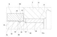
- the outer peripheral surface of the small diameter shaft portion 21a has a small diameter portion 56 constituting one axial side portion, a large diameter portion 57 constituting the other axial side portion, and a step surface 58 facing one axial side that connects the small diameter portion 56 and the large diameter portion 57.
- the outer diameter of the small diameter portion 56 is equal to or smaller than the diameter of the inscribed circle of the locking protrusion 43 of the retaining member 6, and the outer diameter of the large diameter portion 57 is larger than the diameter of the inscribed circle of the locking protrusion 43.
- the locking groove 25 is provided in the large diameter portion 57.
- the small diameter portion 56 is provided on the outer peripheral surface of the small diameter shaft portion 21a from the end on one axial side to the middle part in the axial direction, and is composed of a cylindrical surface whose outer diameter does not change in the axial direction except for the chamfered portion on the edge part on one axial side.
- the large diameter portion 57 is provided on the outer peripheral surface of the small diameter shaft portion 21a at the end on the other axial side, and is composed of a cylindrical surface whose outer diameter does not change in the axial direction except for the portion where the locking groove 25 is present.
- the step surface 58 is composed of a conical surface that is inclined in the direction toward the other axial side as it moves radially outward.
- the locking groove 25 is provided on the end on the other axial side of the large diameter portion 57.
- the small diameter shaft portion 21a is supported on one axial side of the input shaft portion 15 of the input member 3 by a sliding bearing 31 so that it can rotate freely relative to the input member 3.
- the outer diameter of the small diameter portion 56 constituting the one axial side portion of the outer peripheral surface of the small diameter shaft portion 21a is equal to or smaller than the diameter of the inscribed circle of the locking protrusion 43
- the outer diameter of the large diameter portion 57 constituting the other axial side portion of the outer peripheral surface of the small diameter shaft portion 21a is larger than the diameter of the inscribed circle of the locking protrusion 43, and the locking groove 25 is provided in the large diameter portion 57.
- the distance over which the locking protrusion 43 is moved axially while being elastically expanded in diameter can be shortened. This improves assembly workability and effectively prevents damage to the locking protrusion 43.
- the configuration and effects of the other parts of the second example are the same as those of the first example.
- the first spacer portion 38a has discontinuous portions 45 at two locations in the circumferential direction. More specifically, the discontinuous portions 45 are provided at two locations located on both sides of the short side of the longitudinal center of the first spacer portion 38a.
- the expansion/contraction rigidity of the first through hole 41 and the locking protrusion 43 is further reduced. This makes it easier to move the outer circumferential surface of the small diameter shaft portion 21 in the axial direction while elastically expanding the diameter of the locking protrusion 43 when assembling the retaining member 6a to the output member. This improves the ease of assembly of the reverse input cutoff clutch.
- the configuration and effects of the other parts of the third example are the same as those of the first example.
- the first spacer portion 38b does not have any discontinuous parts anywhere in the circumferential direction, and is connected around the entire circumference.
- the locking protrusions 43a in the first spacer portion 38b are provided at multiple locations spaced apart in the circumferential direction on the inner surface of the first through hole 41. That is, in this example, the circumferential length of each locking protrusion 43a is set short, making it easier for each locking protrusion 43a to elastically deform in the radial direction.
- the radially inner portion of the side surface on the other axial side of each locking protrusion 43a is provided with an inclined surface portion 44 that functions as a guide surface during assembly.
- each of the locking protrusions 43a is easily elastically deformed in the radial direction, when assembling the retaining member 6b to the output member, it is easy to move the outer circumferential surface of the small diameter shaft portion 21 in the axial direction while elastically expanding the diameter of the inscribed circle of the multiple locking protrusions 43a. This improves the ease of assembly of the reverse input cutoff clutch.
- the configuration and effects of the other parts of the fourth example are the same as those of the first example.
- the first spacer portion 38c has both the shape features of the third and fourth examples. That is, the first spacer portion 38c has discontinuous portions 45 at two circumferential locations, located on both short sides of the longitudinal center of the first spacer portion 38c, and has locking protrusions 43a at multiple circumferentially spaced locations on the inner circumferential surface of the first through hole 41.
- the first spacer portion 38d has a first through hole 41a through which the output side engagement portion 19 is inserted.
- the first through hole 41a passes through the center of the first spacer portion 38d in the axial direction, has a substantially oval or rectangular opening shape when viewed from the axial direction, and is large enough that the output side engagement portion 19 can be inserted without rattling.
- the end of the output side engaging portion 19 on one axial side and the end of the small diameter shaft portion 21b on the other axial side are inserted into the first through hole 41a.
- the end of the output side engaging portion 19 on one axial side is inserted without rattling into the other axial side portion of the first through hole 41a.
- the small diameter shaft portion 21b that constitutes the output member 4b does not have a locking groove on its outer circumferential surface.
- the input member 3 has an input member side restricting portion 59 that restricts the retaining member 6d from moving to one axial side relative to the output member 4b by engaging with the first spacer portion 38d.
- the input member side restricting portion 59 is formed by the radial inner end portion of the end face on the other axial side of the input shaft portion 15.
- movement of the retaining member 6d toward one axial side relative to the output member 4b is restricted by the side surface of the first spacer portion 38d on one axial side abutting or closely opposing the input member side restricting portion 59.
- movement of the retaining member 6d toward the other axial side relative to the output member 4b is restricted by the side surface of the second spacer portion 39 on the other axial side abutting or closely opposing the end face 63 on one axial side of the output shaft portion 20.
- the retaining member 6d does not have a locking protrusion and the output member 4b does not have a locking groove, so the structures of the retaining member 6d and the output member 4b can be simplified.
- the halves on both axial sides of the retaining member can be shaped symmetrically to prevent incorrect assembly of the retaining member during assembly.
- the halves on both axial sides of the retaining member are shaped symmetrically to prevent incorrect assembly of the retaining member during assembly, the retaining member can be properly assembled regardless of the axial orientation of the retaining member.
- the axial halves of the retaining member can be intentionally made asymmetrical to prevent incorrect assembly of the retaining member during assembly work, making it easier for assembly workers and assembly equipment to recognize the axial orientation of the retaining member.
- the axial thickness of the first spacer portion and the axial thickness of the second spacer portion can be made different from each other to an extent that they are easily recognizable by workers or robots performing assembly work. That is, as in this example, the axial thickness of the first spacer portion 38d can be made greater than the axial thickness of the second spacer portion 39, or the axial thickness of the second spacer portion can be made greater than the axial thickness of the first spacer portion. As in this example, a chamfer can be provided only on the second spacer portion 39 at the opening edge of the through hole.
- the axial thickness of the first spacer portion and the second spacer portion can be set arbitrarily as long as the strength and function required of the retaining member can be secured.
- the axial thickness of the first spacer portion 38d is greater than the axial thickness of the second spacer portion 39, but if the axial thickness of the first spacer portion 38d is set to be equal to or less than the axial thickness of the second spacer portion 39, it can contribute to shortening the axial dimension of the reverse input cutoff clutch accordingly.
- the configuration and effects of the other parts of the sixth example are the same as those of the first example.
- the structure of the retaining member 6e differs from the retaining member 6d of the sixth example only in that the axial thickness of the first spacer portion 38e is smaller than that of the sixth example.
- the retaining member 6e is assembled to the output member 4, one axial end of the output side engagement portion 19 is inserted into the entire first through hole 41a without any rattling.
- the reverse input cutoff clutch of this example further includes a segmented annular retaining ring 60.
- the radially inner portion of the retaining ring 60 is engaged with a retaining groove 25 provided on a portion of the outer circumferential surface of the small diameter shaft portion 21 of the output member 4 that is located on one axial side of the first spacer portion 38e, more specifically, in this example, on the other axial end of the outer circumferential surface of the small diameter shaft portion 21.
- the first spacer portion 38e engages with the side surface on the other axial direction of the radially outer portion of the retaining ring 60, thereby restricting the movement of the retaining member 6e to one axial direction side relative to the output member 4.
- the method of restricting the movement of the retaining member 6e to the other axial direction side relative to the output member 4 is the same as in the sixth example.
- the structure of the retaining member 6e for restricting the axial position of the retaining member 6e relative to the output member 4 can be simplified because the retaining member 6e does not have a locking protrusion.
- the retaining ring 60 can restrict the axial movement of the retaining member 6e relative to the output member 4 to one side, making it easier to carry out the subsequent assembly process.
- the same retaining member as in the sixth example can also be used.
- the same retaining member as in the sixth example can also be used.
- the axial thickness of the first spacer portion 38e constituting the retaining member 6e is made smaller than in the sixth example, this can contribute to shortening the axial dimension of the reverse input cutoff clutch accordingly.
- Example 8 An eighth example of the embodiment of the present disclosure will be described with reference to Fig. 17(a) and Fig. 17(b) In this example, the structure for restricting the axial position of the holding member 6f with respect to the output member 4c is different from that of the seventh example.
- the structure of the retaining member 6f differs from that of the seventh example only in that it has locking protrusions 43b at two circumferential locations on the inner circumferential surface of the first through hole 41a of the first spacer portion 38f.
- the locking protrusions 43b are provided on both sides of the first spacer portion 38f in the short direction of the other axial end of the inner circumferential surface of the first through hole 41a, extending in the longitudinal direction of the first spacer portion 38f.
- the radially inner portion of the side surface on the other axial side of each locking protrusion 43b is provided with an inclined surface portion 44a that functions as a guide surface during assembly.
- the small diameter shaft portion 21b does not have a locking groove on the outer circumferential surface
- the output side engagement portion 19a has a locking groove 25a at a position that aligns with the two locking protrusions 43b on the outer circumferential surface, specifically, at one axial end of the two flat surfaces 23, to which the respective locking protrusions 43b are locked.
- the two locking protrusions 43b are locked to the two locking protrusions 43b.
- movement of the retaining member 6f to one axial side relative to the output member 4c is restricted by the side surfaces of the two locking protrusions 43b on one axial side abutting against the side surface on one axial side that constitutes part of the inner surface of the locking groove 25a.
- the method of restricting movement of the retaining member 6f to the other axial side relative to the output member 4c is the same as in the sixth example.
- the configurations and effects of the other parts are the same as in the seventh example.
- FIG. 18(a), Fig. 18(b), and Fig. 18(c) A ninth example of the embodiment of the present disclosure will be described with reference to Fig. 18(a), Fig. 18(b), and Fig. 18(c).
- the structure of a holding member 6g is different from that of the sixth example.
- the holding member 6g is made by assembling multiple parts.
- the retaining member 6g is formed by assembling a first spacer portion 38g, a second spacer portion 39a, and two connection portions 40a, which are independent parts.
- the first spacer portion 38g and the second spacer portion 39a are each configured as a flat plate, and have an end face shape that is approximately oval or approximately rectangular when viewed from the axial direction.
- the first spacer portion 38g has a first through hole 41a that penetrates in the axial direction in the center, and has connection holes 61a that penetrate in the axial direction at both ends in the longitudinal direction.
- the second spacer portion 39a has a second through hole 46 that penetrates in the axial direction in the center, and has connection holes 61b that penetrate in the axial direction at both ends in the longitudinal direction.
- connection parts 40a are each configured as a stepped cylinder with small diameter parts 62 at both axial ends.
- the retaining member 6g is assembled by press-fitting the small diameter portions 62 on one axial side of the two connecting portions 40a into the connecting holes 61a on both axial sides of the first spacer portion 38g, and press-fitting the small diameter portions 62 on the other axial side of the two connecting portions 40a into the connecting holes 61b on both axial sides of the second spacer portion 39a.
- the components 38g, 39a, and 40a that make up the holding member 6g each have a simple shape, which helps reduce the manufacturing costs of these components 38g, 39a, and 40a.
- the retaining member is made up of multiple parts as in this example, from the perspective of preventing or suppressing incorrect assembly of the retaining member, it is possible to adopt various aspects for making the halves of the retaining member on both axial sides symmetrical in shape, as in the sixth example, or for making the halves of the retaining member on both axial sides asymmetrical in shape, as in the sixth example.
- the configuration and effects of the other parts of the ninth example are the same as those of the sixth example.
- the urging member 47a is composed of two urging members 47a arranged on both sides of the retaining member 6h in the second direction between the two engaging elements 5.
- Each of the two urging members 47a is composed of a compression coil spring 69.
- the compression coil spring 69 constituting each urging member 47a is held by inserting the protrusions 37 provided on the two engaging elements 5 into both axial sides of the spring.
- Each of the two compression coil springs 69 is elastically compressed in the first direction between the two engaging elements 5.
- the distance between the side surface on the other axial side of the first spacer portion 38h and the side surface on one axial side of the second spacer portion 39b is set to a value slightly larger than the axial thickness of the engaging member 5.
- the axial thickness of the first spacer portion 38h and the second spacer portion 39b constituting the retaining member 6h is greater than in the first example, but when implementing this disclosure, the axial thickness of the first spacer portion 38h and the second spacer portion 39b can be made smaller than in this example, for example, the axial thickness can be made the same as in the first example. This can contribute to shortening the axial dimension of the reverse input cutoff clutch accordingly.
- the outer diameter Dc of each of the two compression coil springs 69 is constant over the entire length of the compression coil spring 69 in the extension direction.
- the extension direction of the compression coil spring 69 is the axial direction of the compression coil spring 69, which in this example coincides with the first direction when the reverse input cutoff clutch is in an assembled state.
- the outer diameter Dc of each of the two compression coil springs 69 changes depending on the compression amount of the compression coil spring 69, but in the application of this example, the amount of change is so small that it can be ignored.
- the outer diameter Dc of each compression coil spring 69 is larger than the axial thickness T5 of the engagement element 5 (Dc> T5 ).
- the outer diameter Dc of each compression coil spring 69 can also be set to be equal to or smaller than the axial thickness T5 of the engagement element 5 (Dc ⁇ T5 ).
- each compression coil spring 69 By adopting such a dimensional relationship (Dc ⁇ T5 ), it is possible to prevent the extension direction end of each compression coil spring 69 from being biasedly abutted against the flat surface portion 36 of the engagement element 5, and therefore it becomes easier to prevent the central axis of each compression coil spring 69 from being tilted with respect to the first direction.
- the assembly method of the reverse input cutoff clutch of this example can also include a step of combining the output member 4, the two engaging members 5, the retaining member 6h, and the two biasing members 47a, and using an assembly jig (not shown) that engages the input side engaged portions 33 of the two engaging members 5, displacing the two engaging members 5 radially toward each other against the elastic biasing forces of the two biasing members 47a, and then inserting the two engaging members 5 axially into the radial inside of the pressed surface 7.
- the configuration and effects of the other parts of the tenth example are the same as those of the first example.
- Example 11 An eleventh example of the embodiment of the present disclosure will be described with reference to Fig. 22 to Fig. 26(b). In this example, the structure of a holding member 6i is different from that of the tenth example.
- connection portion 40b of the retaining member 6i is arranged on either side of the first spacer portion 38i and the second spacer portion 39c in the second direction, and is composed of two connection portions 40b each of which connects the first spacer portion 38i and the second spacer portion 39c and has a retaining hole 68 extending in the first direction.
- Each connecting portion 40b is not particularly limited in shape, so long as it connects the first spacer portion 38i and the second spacer portion 39c, has a retaining hole 68 extending in the first direction, and is configured so as not to impede the movement of other components when the reverse input cut-off clutch 1a is in use.
- each connecting portion 40b is configured in a flat plate shape with the thickness direction being the first direction, and has an end face shape that is approximately rectangular when viewed from the first direction.
- each connection portion 40b is configured as a through hole that passes through the center of the connection portion 40b in the first direction.
- each through hole is configured as a circular hole.
- the ends on both axial sides of the ends of each connecting portion 40b that are close to each other in the second direction are integrally connected to the center in the short direction (first direction) of each of the longitudinal (second direction) ends of the first spacer portion 38i and the second spacer portion 39c.
- the two compression coil springs 69 that make up the two biasing members 47a are fitted and held in the retaining holes 68 of the two connection parts 40b.
- each of the retaining holes provided at the two connection parts of the retaining member can be configured as a bottomed hole that opens only on the side of the engaging element in the first direction, and each of the two compression coil springs can be positioned so as to be elastically compressed between the bottom of the bottomed hole and the engaging element.
- each of the two compression coil springs 69 is slightly smaller than the inner diameter of the retaining hole 68.
- the middle portion of each of the two compression coil springs 69 in the extension direction is fitted into the retaining hole 68 without any radial play, thereby restricting movement of the springs in a direction perpendicular to the first direction relative to the output member 4.
- the engaging element 5 does not have a protrusion 37 (see Figures 19 and 20) on its radially inner surface.
- the radially inner surface of the engaging element 5 is entirely formed of a flat surface portion 36 that is perpendicular to the radial direction of the engaging element 5.
- the output side engaged portion 34 is formed by the widthwise center portion of the flat surface portion 36.
- the assembly method of the reverse input cutoff clutch 1a of this example can also include a step of combining the output member 4, two engaging elements 5, a retaining member 6i, and two compression coil springs 69, and using an assembly jig (not shown) that engages the input side engaged portion 33 of the two engaging elements 5, displacing the two engaging elements 5 in a direction that brings them closer to each other in the radial direction against the elastic biasing force of the two compression coil springs 69, and then inserting the two engaging elements 5 from the axial direction into the radial inside of the pressed surface 7.
- the configuration and effects of the other parts of the 11th example are the same as those of the 10th example.
- Example 12 A twelfth example of the embodiment of the present disclosure will be described with reference to Fig. 27.
- the shape of the small diameter shaft portion 21a of the output member 4a is different from that of the eleventh example.
- the small diameter shaft portion 21a has a shape similar to that of the second example, and the assembly structure of the small diameter shaft portion 21a relative to the input shaft portion 15 of the input member 3 and the assembly structure of the first spacer portion 38i relative to the small diameter shaft portion 21a are also similar to those of the second example.
- Example 12 For this reason, in this example as well, for the same reasons as in Example 2, the assembly workability of the reverse input cutoff clutch can be improved.
- the configuration and effects of the other parts of Example 12 are the same as those of Example 11.
- Example 13 A thirteenth example of the embodiment of the present disclosure will be described with reference to Fig. 28.
- the shape of a first spacer portion 38j constituting a holding member 6j is different from that of the eleventh example.
- the first spacer portion 38j has discontinuous portions 45 at two locations in the circumferential direction of the first through hole 41. More specifically, the discontinuous portions 45 are provided at two locations located on both sides in the short direction (first direction) of the center of the longitudinal direction (second direction) of the first spacer portion 38j.
- Example 13 For this reason, in this example as well, for the same reasons as in Example 3, the assembly workability of the reverse input cutoff clutch can be improved.
- the configuration and effects of the other parts of Example 13 are the same as those of Example 11.
- Example 14 A fourteenth example of the embodiment of the present disclosure will be described with reference to Fig. 29.
- the shape of a first spacer portion 38k constituting a holding member 6k is different from that of the eleventh example.
- the first spacer portion 38k does not have any discontinuous parts anywhere in the circumferential direction of the first through hole 41, and is connected around the entire circumference.
- the locking protrusions 43a in the first spacer portion 38k are provided at multiple locations spaced apart in the circumferential direction on the inner surface of the first through hole 41.
- the radially inner portion of the side surface on the other axial side of each locking protrusion 43a is provided with an inclined surface portion 44 that functions as a guide surface during assembly.
- Example 15 A fifteenth example of the embodiment of the present disclosure will be described with reference to Fig. 30.
- the shape of a first spacer portion 38l constituting a holding member 6l is different from that of the eleventh example.
- the first spacer portion 38l has discontinuous portions 45 at two circumferential locations, located on both sides in the short direction (first direction) of the center of the longitudinal direction (second direction) of the first spacer portion 38l, and has locking protrusions 43a at multiple locations spaced apart in the circumferential direction on the inner surface of the first through hole 41.
- Example 15 For this reason, in this example as well, for the same reasons as in Example 5, the assembly workability of the reverse input cutoff clutch can be further improved.
- the configuration and effects of the other parts of Example 15 are the same as those of Example 11.
- Example 16 A sixteenth example of the embodiment of the present disclosure will be described with reference to Fig. 31.
- the shape of two connection portions 40c constituting a holding member 6m is different from that of the fifteenth example.
- Each of the two connection portions 40c has a discontinuous portion 70 at one location in the circumferential direction of the retaining hole 68.
- the discontinuous portion 70 opens to the inner surface of the retaining hole 68, the outer surface of the connection portion 40c, and both side surfaces in the thickness direction (first direction). Therefore, the inner surface of the retaining hole 68 is discontinuous in the circumferential direction at the location where the discontinuous portion 70 exists.
- the discontinuous portion 70 is provided in the axial center of the end of the connection portion 40c that is toward the center of the retaining member 6d in the second direction.
- the discontinuous portion 70 can be provided in only one of the two connection portions constituting the retaining member.
- the circumferential position of the discontinuous portion 70 provided in the connection portion can be a circumferential position different from that in this example.
- the expansion/contraction rigidity of the first through hole 41 can be reduced by relatively displacing two axially opposing portions of each connection portion 40c sandwiching the discontinuous portion 70 therebetween. Therefore, when assembling the retaining member 6d to the output member 4 (see Figures 24(a) and 24(b)), the task of moving the outer circumferential surface of the small diameter shaft portion 21 in the axial direction while elastically expanding the diameter of the inscribed circle of the multiple locking protrusions 43a can be made easier, further improving the ease of assembly of the reverse input cutoff clutch.
- the configuration and effects of the other portions of the 16th example are the same as those of the 15th example.
- Example 17 A seventeenth example of the embodiment of the present disclosure will be described with reference to Fig. 32.
- the circumferential positions of the discontinuous portions 70 provided in the respective connection portions 40d constituting the holding member 6n are different from those in the sixteenth example.
- each connection portion 40d the discontinuous portion 70 is provided in the axial center of the end portion farthest from the center of the retaining member 6d in the second direction.
- the configuration and effects of the other portions of the 17th example are the same as those of the 15th example.
- Example 18 An eighteenth example of the embodiment of the present disclosure will be described with reference to Fig. 33(a) and Fig. 33(b) In this example, the structure for restricting the axial position of the holding member 6o with respect to the output member 4b is different from that of the eleventh example.
- the same structure as in the sixth example is adopted as the position restriction structure. That is, in this example, the retaining member 6 Mr does not have a locking protrusion, and the output member 4b does not have a locking groove.
- the movement of the retaining member 6 Mr to one axial side relative to the output member 4b is restricted by the side surface of the first spacer portion 38m on one axial side abutting or closely facing the input member side restriction portion 59 of the input member 3.
- the retaining member 6 fair does not have a locking protrusion and the output member 4b does not have a locking groove in the position restriction structure, so the structures of the retaining member 6 Sch and the output member 4b can be simplified.
- the configurations and effects of the other parts of the eighteenth example are the same as those of the eleventh example.
- Example 19 A nineteenth example of the embodiment of the present disclosure will be described with reference to Fig. 34.
- a structure for restricting the axial position of the holding member 6p with respect to the output member 4 is different from that of the eighteenth example.
- the reverse input cutoff clutch in this example further includes a snap ring 60 having a segmented annular shape. The radially inner portion of the snap ring 60 is engaged with a locking groove 25 provided at the end of the outer circumferential surface of the small diameter shaft portion 21 of the output member 4 on the other axial side.
- the first spacer portion 38n of the retaining member 6p engages with the side surface of the radially outer portion of the snap ring 60 on the other axial side, thereby restricting the movement of the retaining member 6p to one axial side relative to the output member 4.
- the manner in which the movement of the retaining member 6p to the other axial side relative to the output member 4 is restricted is the same as in the eighteenth example.
- the retaining member 6p does not have a locking protrusion with respect to the position restriction structure, so the structure of the retaining member 6p can be simplified.
- the configuration and effects of the other parts of the 19th example are the same as those of the 18th example.
- Example 20 A twentieth example of the embodiment of the present disclosure will be described with reference to Fig. 35(a) and Fig. 35(b) In this example, the structure for restricting the axial position of the holding member 6q with respect to the output member 4c is different from that of the 19th example.
- the same structure as in the eighth example is adopted as the position restriction structure. That is, in this example, the structure of the retaining member 6q differs from that of the nineteenth example only in that it has locking protrusions 43b at two circumferential locations on the inner circumferential surface of the first through hole 41a of the first spacer portion 38 1958.
- the locking protrusions 43b are provided on both sides of the lateral direction (first direction) of the first spacer portion 38 1958 in an axial portion (axial middle portion in the illustrated example) of the inner circumferential surface of the first through hole 41a so as to extend in the longitudinal direction (second direction) of the first spacer portion 38 1958.
- the radially inner portion of the side surface on the other axial side of each locking protrusion 43b is provided with an inclined surface portion 44a that functions as a guide surface during assembly.
- the small diameter shaft portion 21b does not have a locking groove on the outer circumferential surface
- the output side engagement portion 19a has a locking groove 25a at a position that aligns with the two locking protrusions 43b on the outer circumferential surface, specifically, at one axial end of the two flat surfaces 23, to which the respective locking protrusions 43b are locked.
- the two locking protrusions 43b are locked to the two locking protrusions 43b.
- movement of the retaining member 6q to one axial side relative to the output member 4c is restricted by the side surfaces of the two locking protrusions 43b on one axial side abutting against the side surface on one axial side that constitutes part of the inner surface of the locking groove 25a.
- the method of restricting movement of the retaining member 6q to the other axial side relative to the output member 4c is the same as in the 19th example.
- the configurations and effects of the other parts are the same as in the 19th example.
- Example 21 A twenty-first example of the embodiment of the present disclosure will be described with reference to Fig. 36 and Fig. 37.
- the structure for restricting the axial position of the holding member 6r with respect to the output member 4d is different from that of the eighteenth example.
- This example differs from the 18th example in that the locking protrusion 43c that locks into the locking groove 25b of the output member 4d is provided on one of the two connection parts 40e of the holding member 6r on the side that faces the output side engagement part 19 in the second direction.
- the locking protrusion 43c is provided at the middle part in the first direction of the axial middle part of the side surface of each connecting portion 40e that faces the output side engaging portion 19 in the second direction.
- the entire side surface on the other axial side of the locking protrusion 43c is configured with an inclined surface portion 44b that functions as a guide surface during assembly.
- the side surface on one axial side of the locking protrusion 43c is configured with a plane perpendicular to the axial direction.
- the locking groove 25b is formed across the entire circumferential width at the same axial position as the two locking protrusions 43c of the two convex curved surfaces 24 that make up the outer peripheral surface of the output side engagement portion 19, and has a rectangular cross-sectional shape.
- the retaining member 6r is attached to the output member 4d with the other axial end of the output side engaging portion 19 inserted without rattle into the second through hole 46 of the second spacer portion 39c, and the one axial end of the output side engaging portion 19 inserted without rattle into the first through hole 41a of the first spacer portion 38n, with the two locking protrusions 43c locked into the two locking grooves 25b.
- movement of the retaining member 6r to one axial side relative to the output member 4d is restricted by the side surface on one axial side of the locking protrusion 43c abutting against the side surface 67a of the inner surface of the locking groove 25b facing the other axial side.
- the method of restricting movement of the retaining member 6r to the other axial side relative to the output member 4d is the same as in the 18th example.
- the configurations and effects of the other parts are the same as in the 18th example.
- the reverse input cutoff clutch of this example has two compression coil springs 69 each equipped with a pressure piece 71 attached to the end of the compression coil spring 69 in the extension direction.
- Each of the two compression coil springs 69 elastically presses both side portions in the second direction of the flat surface portion 36 that constitutes the radial inner surface of the engagement member 5 via the pressure piece 71.
- the pressing piece 71 has a stepped cylindrical shape made up of a large diameter section 72 and a small diameter section 73 arranged coaxially, although this is not limited to this.
- the tip surface 74 of the large diameter section 72 in the axial direction of the pressing piece 71, and the step surface 75 connecting the outer circumferential surface of the large diameter section 72 and the outer circumferential surface of the small diameter section 73, are each made up of a flat surface perpendicular to the central axis of the pressing piece 71.
- pressure pieces 71 are attached to both ends of each compression coil spring 69 in the extension direction.
- the pressure piece 71 is attached to the extension end of the compression coil spring 69 with the small diameter portion 73 inserted into the extension end of the compression coil spring 69 and the stepped surface 75 abutting the extension end edge of the compression coil spring 69, and the tip surface 74 is in surface contact with the flat surface portion 36 of the engagement member 5.
- the compression coil spring 69 elastically presses the stepped surface 75 of the pressure piece 71, thereby elastically pressing the flat surface portion 36 of the engagement member 5 via the pressure piece 71.
- the outer peripheral surface of the pressing piece 71 is fitted into the inner peripheral surface of the retaining hole 68 of the retaining member 6 so as to be able to slide in the extension direction (first direction) of the retaining hole 68.
- the outer peripheral surface of the large diameter portion 72 of the pressing piece 71 is fitted into the inner peripheral surface of the retaining hole 68 so as to be able to slide in the extension direction of the retaining hole 68 without any rattling in the radial direction of the retaining hole 68.
- each compression coil spring 69 elastically presses against the flat surface portion 36 of the engagement member 5 via the pressing piece 71, so that a wide pressing area against the flat surface portion 36 can be ensured, and the flat surface portion 36 can be pressed stably.
- the outer peripheral surface of the pressing piece 71 is fitted into the inner peripheral surface of the retaining hole 68 so as to be able to slide in the extension direction of the retaining hole 68, and the ends on both sides of the extension direction of the compression coil spring 69 do not protrude in the extension direction from the inside of the retaining hole 68. Therefore, even if the compression coil spring 69 is deformed by the centrifugal force generated when the input member 3 rotates, the compression coil spring 69 can be prevented from getting caught on the opening periphery of the retaining hole 68.
- the ends on both sides of the extension direction of the compression coil spring 69 do not protrude from the inside of the retaining hole 68 in the extension direction, so the above-mentioned inconvenience can be prevented, and the compression coil spring 69 can be smoothly compressed regardless of the centrifugal force. Therefore, an appropriate spring force can be applied to the engaging member 5.
- the other configurations and effects of the 22nd example are the same as those of the 11th example.
- each retaining hole 68a constituting the retaining member 6s is provided at both opening end portions in the extension direction with guide surface portions 76 whose inner diameter increases toward the opening side.
- the guide surface portions 76 have a convex arc-shaped cross section.
- the cross section of the guide surface portions can also be linear, as shown by the two-dot chain line ⁇ in Figure 40.
- the inner peripheral surface of the retaining hole 68a is provided with guide surface portions 76 at both opening end portions in the extension direction, each of which has an inner diameter that increases toward the opening side.
- due to the low bending rigidity of the compression coil spring 69 even if the ends of the compression coil spring 69 on both sides in the extension direction are elastically deformed toward the radially outward direction (left side in FIG. 40) around the rotation center axis due to the centrifugal force generated when the reverse input cutoff clutch rotates, this portion is unlikely to get caught on the opening periphery of the retaining hole 68a (part P in FIG. 40). This makes it possible to apply an appropriate spring force to the engaging element.
- the other configurations and effects of the 23rd example are the same as those of the 11th example.
- each compression coil spring 69a becomes smaller from the middle to both sides in the extension direction of the compression coil spring 69a.
- the compression coil spring 69a can be easily inserted inside the retaining hole 68 of the retaining member 6i. Also, due to the low bending rigidity of the compression coil spring 69a, even if the ends on both sides of the extension direction of the compression coil spring 69a are elastically deformed radially outward (to the left in FIG. 41) about the central axis of rotation due to the centrifugal force generated when the reverse input cut-off clutch rotates, these portions are less likely to get caught on the opening periphery of the retaining hole 68a (part P in FIG. 41). This makes it possible to apply an appropriate spring force to the engaging element.
- the other configurations and effects of the 24th example are the same as those of the 11th example.
- the reverse input cutoff clutch of the present disclosure can be implemented by appropriately combining the structures of the first to twenty-fourth examples as long as no contradictions arise.
Landscapes
- Engineering & Computer Science (AREA)
- General Engineering & Computer Science (AREA)
- Mechanical Engineering (AREA)
- Braking Arrangements (AREA)
Priority Applications (2)
| Application Number | Priority Date | Filing Date | Title |
|---|---|---|---|
| JP2024559578A JP7643648B1 (ja) | 2023-07-20 | 2024-07-05 | 逆入力遮断クラッチおよびその組立方法 |
| CN202480047798.7A CN121586814A (zh) | 2023-07-20 | 2024-07-05 | 反向输入切断离合器及其组装方法 |
Applications Claiming Priority (4)
| Application Number | Priority Date | Filing Date | Title |
|---|---|---|---|
| JP2023118255 | 2023-07-20 | ||
| JP2023-118255 | 2023-07-20 | ||
| JP2023-171501 | 2023-10-02 | ||
| JP2023171501 | 2023-10-02 |
Publications (1)
| Publication Number | Publication Date |
|---|---|
| WO2025018179A1 true WO2025018179A1 (ja) | 2025-01-23 |
Family
ID=94281958
Family Applications (1)
| Application Number | Title | Priority Date | Filing Date |
|---|---|---|---|
| PCT/JP2024/024406 Pending WO2025018179A1 (ja) | 2023-07-20 | 2024-07-05 | 逆入力遮断クラッチおよびその組立方法 |
Country Status (3)
| Country | Link |
|---|---|
| JP (1) | JP7643648B1 (https=) |
| CN (1) | CN121586814A (https=) |
| WO (1) | WO2025018179A1 (https=) |
Citations (2)
| Publication number | Priority date | Publication date | Assignee | Title |
|---|---|---|---|---|
| WO2022168764A1 (ja) * | 2021-02-08 | 2022-08-11 | 日本精工株式会社 | 逆入力遮断クラッチ |
| JP2023085990A (ja) * | 2021-12-09 | 2023-06-21 | 日本精工株式会社 | 逆入力遮断クラッチ |
-
2024
- 2024-07-05 WO PCT/JP2024/024406 patent/WO2025018179A1/ja active Pending
- 2024-07-05 JP JP2024559578A patent/JP7643648B1/ja active Active
- 2024-07-05 CN CN202480047798.7A patent/CN121586814A/zh active Pending
Patent Citations (2)
| Publication number | Priority date | Publication date | Assignee | Title |
|---|---|---|---|---|
| WO2022168764A1 (ja) * | 2021-02-08 | 2022-08-11 | 日本精工株式会社 | 逆入力遮断クラッチ |
| JP2023085990A (ja) * | 2021-12-09 | 2023-06-21 | 日本精工株式会社 | 逆入力遮断クラッチ |
Also Published As
| Publication number | Publication date |
|---|---|
| JPWO2025018179A1 (https=) | 2025-01-23 |
| JP7643648B1 (ja) | 2025-03-11 |
| CN121586814A (zh) | 2026-02-27 |
Similar Documents
| Publication | Publication Date | Title |
|---|---|---|
| EP1886895B1 (en) | Assembly of a shaft and a housing assembly | |
| US20110005881A1 (en) | Clutch unit | |
| US7037200B2 (en) | Coupling arrangement | |
| JP7509335B1 (ja) | 逆入力遮断クラッチ | |
| JP7327712B1 (ja) | 逆入力遮断クラッチ | |
| US11629768B2 (en) | Reverse input cutoff clutch | |
| JP7643648B1 (ja) | 逆入力遮断クラッチおよびその組立方法 | |
| JP2001159429A (ja) | 電動パワーステアリング装置 | |
| JP3536602B2 (ja) | シールリングの取り付け構造 | |
| JP7375991B1 (ja) | 逆入力遮断クラッチおよびその組立方法 | |
| JP2020133868A (ja) | 逆入力遮断クラッチ | |
| WO2024247372A1 (ja) | 逆入力遮断クラッチ | |
| JP4513158B2 (ja) | 摩擦ローラ式変速機 | |
| JP7375989B1 (ja) | 逆入力遮断クラッチ | |
| JP2022126361A (ja) | 逆入力遮断クラッチ付電動モータ | |
| JP7443603B1 (ja) | 双方向トルクリミッタ | |
| JP2025125461A (ja) | 逆入力遮断クラッチ | |
| WO2023233801A1 (ja) | 逆入力遮断クラッチ | |
| WO2026053731A1 (ja) | 逆入力遮断クラッチ | |
| JP2008275123A (ja) | 一方向クラッチおよび一方向クラッチの製造方法 | |
| JPH09189325A (ja) | スラストころ軸受 | |
| JP2001241465A (ja) | 自動調心型クラッチレリーズ軸受 | |
| JP2024000174A (ja) | 等速自在継手及びその製造方法 | |
| JP2023175529A (ja) | 逆入力遮断クラッチ | |
| JP2023022882A (ja) | 逆入力遮断クラッチ |
Legal Events
| Date | Code | Title | Description |
|---|---|---|---|
| WWE | Wipo information: entry into national phase |
Ref document number: 2024559578 Country of ref document: JP |
|
| 121 | Ep: the epo has been informed by wipo that ep was designated in this application |
Ref document number: 24842972 Country of ref document: EP Kind code of ref document: A1 |