WO2025013930A1 - カテーテルおよび処置方法、並びにガイドワイヤおよびカテーテルシステム - Google Patents
カテーテルおよび処置方法、並びにガイドワイヤおよびカテーテルシステム Download PDFInfo
- Publication number
- WO2025013930A1 WO2025013930A1 PCT/JP2024/025223 JP2024025223W WO2025013930A1 WO 2025013930 A1 WO2025013930 A1 WO 2025013930A1 JP 2024025223 W JP2024025223 W JP 2024025223W WO 2025013930 A1 WO2025013930 A1 WO 2025013930A1
- Authority
- WO
- WIPO (PCT)
- Prior art keywords
- tip
- catheter
- guidewire
- outer diameter
- constant
- Prior art date
- Legal status (The legal status is an assumption and is not a legal conclusion. Google has not performed a legal analysis and makes no representation as to the accuracy of the status listed.)
- Pending
Links
Images





Classifications
-
- A—HUMAN NECESSITIES
- A61—MEDICAL OR VETERINARY SCIENCE; HYGIENE
- A61M—DEVICES FOR INTRODUCING MEDIA INTO, OR ONTO, THE BODY; DEVICES FOR TRANSDUCING BODY MEDIA OR FOR TAKING MEDIA FROM THE BODY; DEVICES FOR PRODUCING OR ENDING SLEEP OR STUPOR
- A61M25/00—Catheters; Hollow probes
- A61M25/0043—Catheters; Hollow probes characterised by structural features
-
- A—HUMAN NECESSITIES
- A61—MEDICAL OR VETERINARY SCIENCE; HYGIENE
- A61M—DEVICES FOR INTRODUCING MEDIA INTO, OR ONTO, THE BODY; DEVICES FOR TRANSDUCING BODY MEDIA OR FOR TAKING MEDIA FROM THE BODY; DEVICES FOR PRODUCING OR ENDING SLEEP OR STUPOR
- A61M25/00—Catheters; Hollow probes
- A61M25/01—Introducing, guiding, advancing, emplacing or holding catheters
- A61M25/06—Body-piercing guide needles or the like
- A61M25/0662—Guide tubes
-
- A—HUMAN NECESSITIES
- A61—MEDICAL OR VETERINARY SCIENCE; HYGIENE
- A61M—DEVICES FOR INTRODUCING MEDIA INTO, OR ONTO, THE BODY; DEVICES FOR TRANSDUCING BODY MEDIA OR FOR TAKING MEDIA FROM THE BODY; DEVICES FOR PRODUCING OR ENDING SLEEP OR STUPOR
- A61M25/00—Catheters; Hollow probes
- A61M25/01—Introducing, guiding, advancing, emplacing or holding catheters
- A61M25/06—Body-piercing guide needles or the like
- A61M25/0662—Guide tubes
- A61M2025/0681—Systems with catheter and outer tubing, e.g. sheath, sleeve or guide tube
-
- A—HUMAN NECESSITIES
- A61—MEDICAL OR VETERINARY SCIENCE; HYGIENE
- A61M—DEVICES FOR INTRODUCING MEDIA INTO, OR ONTO, THE BODY; DEVICES FOR TRANSDUCING BODY MEDIA OR FOR TAKING MEDIA FROM THE BODY; DEVICES FOR PRODUCING OR ENDING SLEEP OR STUPOR
- A61M25/00—Catheters; Hollow probes
- A61M25/01—Introducing, guiding, advancing, emplacing or holding catheters
- A61M25/09—Guide wires
- A61M2025/09058—Basic structures of guide wires
- A61M2025/09075—Basic structures of guide wires having a core without a coil possibly combined with a sheath
-
- A—HUMAN NECESSITIES
- A61—MEDICAL OR VETERINARY SCIENCE; HYGIENE
- A61M—DEVICES FOR INTRODUCING MEDIA INTO, OR ONTO, THE BODY; DEVICES FOR TRANSDUCING BODY MEDIA OR FOR TAKING MEDIA FROM THE BODY; DEVICES FOR PRODUCING OR ENDING SLEEP OR STUPOR
- A61M25/00—Catheters; Hollow probes
- A61M25/0067—Catheters; Hollow probes characterised by the distal end, e.g. tips
- A61M25/0068—Static characteristics of the catheter tip, e.g. shape, atraumatic tip, curved tip or tip structure
Definitions
- the present invention relates to a catheter and a treatment method, as well as a guidewire and a catheter system.
- the target blood vessels for deep vein thrombosis are veins more peripheral than the inferior vena cava, such as the iliac vein, femoral vein or popliteal vein.
- the diameter of a vein is generally larger than that of an artery. For example, the inner diameter of an artery through which a catheter is accessed is about 3 Fr to 8 Fr, whereas the inner diameter of a vein through which a catheter is accessed is about 6 Fr to 24 Fr.
- the present invention has been made to solve the above-mentioned problems, and aims to provide a penetrating catheter and treatment method that has high penetrating ability for venous lesions while effectively supporting a device inserted therein and improving the operability of the supported device, as well as a guidewire and catheter system that has high penetrating ability for venous lesions.
- the penetrating catheter of the present invention is a penetrating catheter used for penetrating a venous lesion, and has a tubular body having a constant outer diameter portion whose outer diameter is constant in the longitudinal direction, an outer tapered portion whose outer diameter tapers from the tip of the constant outer diameter portion toward the tip, a constant inner diameter portion whose inner diameter is constant in the longitudinal direction, and an inner tapered portion whose inner diameter tapers from the tip of the constant inner diameter portion toward the tip, characterized in that the outer diameter of the constant outer diameter portion is 2.7 mm, the inner diameter of the constant inner diameter portion is 1.6 mm, the outer diameter of the tip of the tubular body is 1.6 mm, and the inner diameter of the tip of the tubular body is 1.45 mm.
- the penetrating catheter described in (1) above has a large wall thickness defined by the constant outer diameter portion and the constant inner diameter portion, and is highly rigid, and the outer tapered portion has a narrow tip, so that it has high penetrability into lesions and can penetrate lesions that are difficult to penetrate with the penetrating catheter itself.
- the high rigidity allows the device inserted into the penetrating catheter to be effectively supported, and the operability of the supported device can be improved.
- the tubular body may have a curved portion at the tip that is bent at an angle of 20 degrees to 30 degrees. This allows the penetration catheter to adjust the direction of the tip by rotating it, improving operability.
- a treatment method for achieving the above object is a treatment method for penetrating a venous lesion, characterized in that the penetrating catheter has a tubular body having a constant outer diameter portion with a constant outer diameter in the longitudinal direction, an outer tapered portion whose outer diameter tapers from the tip of the constant outer diameter portion toward the tip, a constant inner diameter portion with a constant inner diameter in the longitudinal direction, and an inner tapered portion whose inner diameter tapers from the tip of the constant inner diameter portion toward the tip, the outer diameter of the constant outer diameter portion is 2.7 mm, the inner diameter of the constant inner diameter portion is 1.6 mm, the outer diameter of the tip of the tubular body is 1.6 mm, and the inner diameter of the tip of the tubular body is 1.45 mm, and an inner catheter is inserted into the penetrating catheter, and in a state where a guidewire is inserted into the inner catheter, the penetrating catheter is penetrated into the venous lesion together with the guidewire and the inner catheter.
- the penetrating catheter used in this treatment method has a large wall thickness defined by the constant outer diameter portion and the constant inner diameter portion of the tubular body, and is highly rigid, and the tip of the outer tapered portion is narrow, so that it has high penetrating ability into the lesion. Therefore, this treatment method allows the penetrating catheter itself to penetrate lesions that are difficult to penetrate. In addition, this treatment method allows the inner catheter and guidewire inserted into the penetrating catheter to be effectively supported with high rigidity, and improves the operability of the supporting device.
- a guidewire for achieving the above object has a long core wire made of metal and a coating layer that covers at least the tip of the core wire and is softer than the core wire, the core wire having a constant core wire outer diameter portion with a constant outer diameter and a core wire tapered portion in which the outer diameter decreases in a tapered manner from the tip of the constant core wire outer diameter portion to the very end of the core wire, the portion of the guidewire having the core wire tapered portion is formed linearly, and in a load test that measures the load when the guidewire is pushed in the tip direction with the tip of the guidewire abutted against a non-slip receiving portion, the measured load exceeds 0.04 N when pushed 0.05 mm, exceeds 0.05 N when pushed 0.1 mm, and exceeds 0.05 N when pushed 0.2 mm.
- the above guidewire has high penetration into lesions due to the high load in the load test.
- a guidewire for achieving the above object is a guidewire having a long core wire made of metal and a coating layer that covers at least the tip of the core wire and is softer than the core wire, the core wire having a constant outer diameter portion having a constant outer diameter and a core wire tapered portion in which the outer diameter decreases in a tapered manner from the tip of the constant outer diameter portion to the tip of the core wire, the guidewire having a guidewire tip at the tip, a guidewire curved portion that is curved and located on the base end side of the guidewire tip, and a straight guidewire straight portion that is straight and located on the base end side of the guidewire curved portion.
- the tip bending angle which is the angle at which the line segment connecting the tip of the guidewire and the curved base portion is inclined with respect to the extension line of the guidewire straight portion, is 25 degrees to 40 degrees, and in a load test in which the tip of the guidewire is abutted against a non-slip receiving portion and the weight applied when the guidewire is pushed toward the tip direction is measured with the guidewire inserted into the inner catheter and the inner catheter inserted into the penetration catheter, the measured weight exceeds 0.02 N when pushed 0.2 mm and exceeds 0.04 N when pushed 2.0 mm. Since the guidewire has a guidewire curved portion, the direction of the tip can be adjusted by rotating it, improving operability. Furthermore, the guidewire has high penetrability into lesions because the weight applied in the load test is high.
- a catheter system for achieving the above object includes a penetrating catheter used for penetrating a venous lesion, an inner catheter that can be inserted into the penetrating catheter, and the guide wire described in (4) above that can be inserted into the inner catheter, and is characterized in that in a load test in which the inner catheter is inserted into the penetrating catheter, the guide wire is inserted into the inner catheter, and the catheter system is pushed toward the tip with the tip of the guide wire abutting against a non-slip receiving portion, the measured load exceeds 0.1 N when pushed 0.2 mm.
- the catheter system has high penetrating ability into a lesion because of the high load in the load test.
- a catheter system for achieving the above object includes a penetrating catheter used for penetrating a venous lesion, an inner catheter that can be inserted into the penetrating catheter, and the guide wire described in (5) above that can be inserted into the inner catheter, and is characterized in that in a load test in which the inner catheter is inserted into the penetrating catheter, the guide wire is inserted into the inner catheter, and the catheter system is pushed toward the tip with the tip of the guide wire abutting against a non-slip receiving portion, the measured load exceeds 0.02 N when pushed 0.2 mm, and exceeds 0.04 N when pushed 2.0 mm. Since the catheter system has a guide wire curved portion on the guide wire, the direction of the tip can be adjusted by rotating it, improving operability. Furthermore, the catheter system has high penetrating ability into lesions because the load in the load test is high.
- FIG. 2 is a plan view showing the catheter system in an assembled state.
- FIG. 2 is a plan view showing the catheter system in a separated state.
- 1 is a cross-sectional view showing the tip of a penetration catheter according to an embodiment of the present invention.
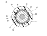
- FIG. 2 is a cross-sectional view taken along line AA in FIG. 1.
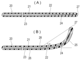
- 1A and 1B are cross-sectional views showing a guidewire, in which FIG. 1A shows a first example and FIG. 1A and 1B are schematic diagrams showing a state in which a load test is being performed on a catheter system, and FIG. 1B shows a state in which a load test is being performed on a guidewire.
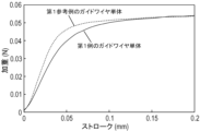
- 11 is a graph showing load versus stroke in a load test using the guide wire of the first example.
- FIG. 8 is a graph showing a load relative to a stroke, the graph being an enlarged view of a portion of FIG. 7 .
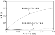
- 13 is a graph showing load versus stroke in a load test using the guide wire of the second example.
- 10 is a graph showing a load relative to a stroke, the graph being an enlarged view of a portion of FIG. 9 .
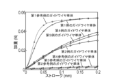
- 1 is a graph showing load versus stroke in a load test of a guidewire alone.
- a penetration catheter 40 constitutes a catheter system 10 together with other devices and is used to penetrate a lesion in the treatment of deep vein thrombosis (DVT).
- the catheter system 10 is inserted into a vein at the femoral, knee or more distal, and advanced into the blood vessel to be treated.
- the blood vessel to be treated is a vein more distal than the inferior vena cava (e.g., the iliac, femoral or popliteal vein).
- the catheter system 10 includes a penetrating catheter 40, an inner catheter 30 that can be inserted into the penetrating catheter 40, and a guidewire 20 that can be inserted into the inner catheter 30.
- At least the outer circumferential surface of the tip of the second tube 41 may be coated with a lubricating coat 44 (see Figs. 1 and 2).
- the lubricating coat 44 is coated over a range from the tip of the second tube 41 to a predetermined distance L2 (e.g., 400 mm) in the direction toward the base end.
- the lubricating coat 44 is, for example, a hydrophilic polymer, and examples of the lubricating coat include cellulose-based polymers, polyethylene oxide-based polymers, maleic anhydride-based polymers (e.g., maleic anhydride copolymers such as methyl vinyl ether-maleic anhydride copolymers), acrylamide-based polymers (e.g., polyacrylamide, glycidyl methacrylate-dimethylacrylamide block copolymers), water-soluble nylon, polyvinyl alcohol, polyvinylpyrrolidone, and derivatives thereof.
- cellulose-based polymers e.g., polyethylene oxide-based polymers
- maleic anhydride-based polymers e.g., maleic anhydride copolymers such as methyl vinyl ether-maleic anhydride copolymers
- acrylamide-based polymers e.g., polyacrylamide, glycidyl methacrylate-dimethylacrylamide block copo
- Hydrophilic polymers form a strong water immobilization layer on their surface, and exhibit high affinity to the blood in the blood vessel and the blood vessel wall surface, as well as low friction.
- the lubricating coat 44 may be a fluororesin such as polytetrafluoroethylene (PTFE), a low-friction material such as high-density polyethylene (HDPE), etc.
- PTFE polytetrafluoroethylene
- HDPE high-density polyethylene
- the second tube 41 has a constant outer diameter portion 45 with a substantially constant outer diameter, an outer tapered portion 46 with an outer diameter that tapers from the tip of the constant outer diameter portion 45 toward the tip, a constant inner diameter portion 47 with a substantially constant inner diameter, an inner tapered portion 48 with an inner diameter that tapers from the tip of the constant inner diameter portion 47 toward the tip, and a constant inner diameter tip portion 49 with a substantially constant inner diameter from the tip of the inner tapered portion 48 toward the tip.
- the second tube 41 has a curved portion 50 within the length L6 of the tip of the constant outer diameter portion 45.
- the length L6 is not particularly limited, but is, for example, 10 mm.
- the curved angle ⁇ of the curved portion 50 is not particularly limited, but is preferably 20 degrees to 30 degrees, and is, for example, 30 degrees.
- the second tube 41 does not have to have a curved portion 50.
- the second tube 41 is formed of an inner layer 51 that forms the inner surface of the second tube 41, an outer layer 52 that forms the outer surface of the second tube 41, and a reinforcing body 53 located between the inner layer 51 and the outer layer 52.
- the second tube 41 has a flexible portion 55 in which the reinforcing body 53 is not disposed, further distal than the region in which the reinforcing body 53 is disposed.
- the length L7 in the longitudinal direction of the flexible portion 55 is 20 mm to 30 mm.
- the reinforcing body 53 is for reinforcing the second tube 41 and has a plurality of reinforcing wires 54 (for example, 16 wires).
- the material of the outer layer 52 or the inner layer 51 enters the gaps between the reinforcing wires 54 in the reinforcing body 53.
- the reinforcing body 53 may be a tube-shaped braid of reinforcing wires 54.
- the reinforcing body 53 may be formed by winding one or more reinforcing wires 54 in a spiral (coil) shape.
- the reinforcing wires 54 are made of metal such as stainless steel or NiTi.
- the cross-sectional shape of the reinforcing wires 54 is not particularly limited, and may be, for example, a rectangle, a square, a circle, an oval, or an ellipse.
- one reinforcing wire 54 may be a bundle of two or more wires.
- the second tube 41 having the reinforcing body 53 can ensure sufficient rigidity and strength without increasing the wall thickness, i.e., while making the inner diameter of the second tube 41 relatively large.
- the inner layer 51 is preferably formed from a low-friction material. This allows devices such as the inner catheter 30 and the guidewire 20 to move in the longitudinal direction with little sliding resistance when they are inserted into and removed from the second lumen 42, improving operability.
- low-friction materials include fluorine-based resin materials such as polytetrafluoroethylene (PTFE) and tetrafluoroethylene-perfluoroalkoxyethylene copolymer (PFA).
- Materials constituting the outer layer 52 include, for example, polystyrene, polyolefin, polyurethane, polyester, polyamide, and various thermoplastic elastomers such as styrene-based, polyolefin-based, polyurethane-based, polyester-based, polyamide-based, polybutadiene-based, trans-polyisoprene-based, fluororubber-based, and chlorinated polyethylene-based, and combinations of one or more of these (polymer alloys, polymer blends, laminates, etc.) can also be used.
- polystyrene, polyolefin, polyurethane, polyester, polyamide, and various thermoplastic elastomers such as styrene-based, polyolefin-based, polyurethane-based, polyester-based, polyamide-based, polybutadiene-based, trans-polyisoprene-based, fluororubber-based, and chlorinated polyethylene-based, and
- the effective length L1 of the penetrating catheter 40 is not particularly limited, but is preferably 650 mm to 900 mm, for example 650 mm.
- the effective length L1 of the penetrating catheter 40 is the length of the portion that can be inserted into a blood vessel or a tubular device.
- the effective length L1 of the penetrating catheter 40 is the length from the tip of the second hub 43 or the anti-kink protector at the base end to the tip of the second tubular body 41.
- the outer diameter D1 of the constant outer diameter portion 45 is 2.7 ⁇ 0.1 mm
- the outer diameter D2 of the tip of the outer tapered portion 46 is 1.7 ⁇ 0.1 mm
- the inner diameter D3 of the constant inner diameter portion 47 is 1.6 ⁇ 0.1 mm
- the inner diameter D4 of the tip constant inner diameter portion 49 is 1.45 ⁇ 0.1 mm.
- the thickness T at the position where the constant outer diameter portion 45 and the constant inner diameter portion 47 overlap is 0.55 mm. If the inner diameters D3 and D4 are smaller than this, the frictional resistance with the inner catheter 30 is large, and if they are larger than this, the penetrating catheter 40 is more likely to kink.
- the long axis length L3 of the outer tapered portion 46 is 12 mm
- the long axis length L4 of the inner tapered portion 48 is 3 mm
- the long axis length L5 of the tip constant inner diameter portion 49 is 7 mm.
- the inner catheter 30 is a catheter that fills the space between the penetrating catheter 40 and the guidewire 20, increasing the rigidity of the catheter system 10 and improving its penetrability, while suppressing bending of the guidewire 20 inside the penetrating catheter 40 and the inner catheter 30, and expanding the gap in the lesion formed by the guidewire 20 that has entered the lesion.
- the inner catheter 30 has a first tubular body 31 in which a first lumen 32 into which the guidewire 20 can be inserted is formed, and a first hub 33 fixed to the base end of the first tubular body 31.
- the inner catheter 30 covers and supports the guidewire 20 inserted into the first lumen 32, and penetrates the lesion together with the guidewire 20 and the penetrating catheter 40.
- the outer diameter of the first tube 31 is not particularly limited, but is preferably a size that allows it to slide smoothly while adhering closely to the second lumen 42 of the penetrating catheter 40, for example 1.4 mm.
- the inner diameter of the first tube 31 is preferably a size that allows the guidewire 20 inserted into the first lumen 32 to slide while adhering closely to the second lumen 42, for example 1.0 mm.
- the inner catheter 30 may be a NaviCross (registered trademark) manufactured by Terumo Corporation, into which a guidewire 20 with an outer diameter of 0.035 inches (0.9 mm) can be inserted.
- the guidewire 20 preferably has high penetrability so that it can penetrate venous lesions.
- the guidewire 20 preferably has a higher rigidity at the tip than a typical guidewire 20 so that it can achieve high penetrability.
- the guidewire 20 may be a wire with an outer diameter of 0.035 inches (0.9 mm) made by Terumo Corporation's Glidewire Advantage (registered trademark) with the soft tip portion (20 mm to 30 mm from the tip toward the base end) removed.
- the catheter system 10 is a combination of a penetrating catheter 40, an inner catheter 30, and a guidewire 20, and is used to penetrate not only the guidewire 20 but also the inner catheter 30 and the penetrating catheter 40 into a venous lesion (e.g., an organized thrombus).
- a venous lesion e.g., an organized thrombus
- the penetrating catheter 40 of this embodiment is a penetrating catheter 40 used to penetrate a venous lesion, and has a second tubular body 41 having a constant outer diameter portion 45 whose outer diameter is constant in the longitudinal direction, an outer tapered portion 46 whose outer diameter tapers from the tip of the constant outer diameter portion 45 toward the tip, a constant inner diameter portion 47 whose inner diameter is constant in the longitudinal direction, and an inner tapered portion 48 whose inner diameter tapers from the tip of the constant inner diameter portion 47 toward the tip, and the outer diameter of the constant outer diameter portion 45 is 2.7 ⁇ 0.1 mm, the inner diameter of the constant inner diameter portion 47 is 1.6 ⁇ 0.1 mm, the outer diameter of the tip of the tube is 1.7 ⁇ 0.1 mm, and the inner diameter of the tip of the second tubular body 41 is 1.45 ⁇ 0.1 mm.
- the penetrating catheter 40 has a large wall thickness defined by the constant outer diameter portion 45 and the constant inner diameter portion 47, and is highly rigid, and the outer tapered portion 46 has a narrow tip, so that the penetrating catheter 40 itself can penetrate lesions that are difficult to penetrate (such as organized thrombus).
- the high rigidity of the penetrating catheter 40 allows it to effectively support devices (the inner catheter 30 and the guidewire 20) inserted into the penetrating catheter 40, and improves the operability of the supported devices (the inner catheter 30 and the guidewire 20).
- the second tube 41 has a curved section 50 at the tip that is bent at an angle of 20 to 30 degrees. This allows the penetrating catheter 40 to be rotated to adjust the direction of the tip, improving operability.
- the treatment method in this embodiment is a treatment method for penetrating a venous lesion, and is characterized in that the penetrating catheter 40 has a second tubular body 41 having a constant outer diameter portion 45 whose outer diameter is constant in the longitudinal direction, an outer tapered portion 46 whose outer diameter tapers off from the tip of the constant outer diameter portion 45 toward the tip, a constant inner diameter portion 47 whose inner diameter is constant in the longitudinal direction, and an inner tapered portion 48 whose inner diameter tapers off from the tip of the constant inner diameter portion 47 toward the tip, and the inner catheter 30 is inserted into the penetrating catheter 40, the constant outer diameter portion 45 having an outer diameter of 2.7 ⁇ 0.1 mm, the constant inner diameter portion 47 having an inner diameter of 1.6 ⁇ 0.1 mm, the outer diameter of the most distal end of the second tubular body 41 being 1.7 ⁇ 0.1 mm, and the inner diameter of the most distal end of the second tubular body 41 being 1.45 ⁇ 0.1 mm, and with a guidewire 20 inserted into the inner catheter 30, the
- the second tubular body 41 of the penetrating catheter 40 used in this treatment method has a large wall thickness defined by the constant outer diameter portion 45 and the constant inner diameter portion 47, and the outer tapered portion 46 has a narrow tip, so that the penetrating catheter 40 has high penetrating ability into the lesion.
- This treatment method therefore allows the penetrating catheter 40 itself to penetrate lesions that are difficult to penetrate (e.g., organized thrombus).
- This treatment method also allows the inner catheter 30 and guidewire 20 inserted into the penetrating catheter 40 to be effectively supported by the high rigidity, and improves the operability of the supported devices.
- the first example of the guidewire 20, as shown in FIG. 5(A), comprises a long core wire 21 and a coating layer 22 that covers the core wire 21.
- the core wire 21 extends over almost the entire length of the guide wire 20.
- the core wire 21 is formed from a single continuous wire.
- the cross-sectional shape of the core wire 21 perpendicular to its long axis is circular, but does not have to be circular.
- the core wire 21 comprises a core wire constant outer diameter portion 23 and a core wire tapered portion 24 disposed from the tip of the core wire constant outer diameter portion 23 to the very end of the core wire 21.
- the core wire constant outer diameter portion 23 has a nearly constant outer diameter along the long axis.
- the core wire tapered portion 24 has an outer diameter that gradually decreases from the tip of the core wire constant outer diameter portion 23 toward the tip.
- the outer diameter of the core wire constant outer diameter portion 23 is, for example, 0.65 mm to 0.75 mm.
- the outer diameter of the very end of the core wire tapered portion 24 is, for example, 0.14 mm to 0.30 mm.
- the constant core wire outer diameter portion 23 provides the guidewire 20 with desirable pushability due to its constant outer diameter.
- the tapered core wire portion 24 gradually reduces the rigidity of the guidewire 20 from the constant core wire outer diameter portion 23 toward the tip. This allows the guidewire 20 to be less susceptible to localized bending, such as kinking, or damage.
- the material for forming the core wire 21 can be a metal material, for example, a superelastic alloy such as a Ni-Ti alloy, a Ni-Al alloy, or a Cu-Zn alloy, or an alloy containing these.
- a superelastic alloy such as a Ni-Ti alloy, a Ni-Al alloy, or a Cu-Zn alloy, or an alloy containing these.
- the coating layer 22 covers at least the tip of the core wire 21.
- the coating layer 22 protects the outer surface of the core wire 21 and improves safety when inserting the guide wire 20 into a biological lumen such as a blood vessel.
- the material from which the coating layer 22 is made is preferably a highly flexible material, and may be, for example, a polyolefin such as polyurethane, polyethylene, or polypropylene, polyvinyl chloride, polyester (PET, PBT, etc.), polyamide, polyimide, polystyrene, silicone resin, thermoplastic elastomer such as polyurethane elastomer, polyester elastomer, or polyamide elastomer, various rubber materials such as latex rubber or silicone rubber, fluororesin, or a composite material combining two or more of these.
- the outer diameter of the coating layer 22 is, for example, 0.60 mm to 0.89 mm.
- the entire coating layer 22 may be coated with a resin made of a mixture of polyurethane and tungsten, or the tip may be coated with a resin made of a mixture of polyurethane and tungsten, and the base end may be coated with a fluororesin such as PTFE.
- the coating layer 22 may be covered with a lubricating layer (not shown).
- the lubricating layer is formed of a hydrophilic polymer that reduces friction.
- the hydrophilic polymer creates a strong water immobilization layer on its surface, and exhibits high affinity for the blood in the blood vessel and the blood vessel wall surface, as well as low friction (low friction coefficient).
- the lubricating layer only needs to cover at least the tip of the coating layer 22, but may cover the entire length.
- the guidewire 20 may have a guidewire curved section 25 at the tip where the core wire tapered section 24 is located, as in the second example shown in FIG. 5(B).
- the guidewire 20 has a guidewire straight section 26 on the proximal side of the guidewire curved section 25.
- the guidewire 20 has a guidewire tip 27 at its most distal end, and a curved base 28 between the guidewire straight section 26 and the guidewire curved section 25.
- the tip curve angle ⁇ which is the angle at which the line segment connecting the curved base 28 and the guidewire tip 27 is inclined with respect to the extension line of the guidewire straight section 26, is not particularly limited, but is preferably 25 degrees to 40 degrees.
- the length from the curved base 28 to the guidewire tip 27 along the long axis of the guidewire 20 is not particularly limited, but is preferably 3 mm to 5 mm.
- the end face of the guidewire tip 27 is formed into a roughly hemispherical shape with a curvature. Therefore, compared to when the end face is a horizontal surface, it can make point contact with the contact object, making it less slippery and easier to get into gaps.
- the end face of the guidewire tip 27 may be covered with a lubricating layer, but it does not have to be. If the guidewire 20 has a lubricating layer on its surface but the end face of the guidewire tip 27 does not have a lubricating layer, the guidewire tip 27 will be less slippery and will be easier to get into gaps.
- the penetrating catheter 40 may have a curved portion 50, the inner catheter 30 may not have a curved portion, and the guidewire 20 may have a guidewire curved portion 25.
- the penetrating catheter 40 may have a curved portion 50, the inner catheter 30 may not have a curved portion, and the guidewire 20 may not have a guidewire curved portion 25.
- the penetrating catheter 40 may not have a curved portion 50, the inner catheter 30 may not have a curved portion, and the guidewire 20 may not have a guidewire curved portion 25.
- the direction of the tip of the penetrating catheter 40 can be changed by rotating it, which is effective, for example, when puncturing.
- the guidewire 20 has a guidewire curved portion 25
- the direction of the tip of the guidewire 20 can be changed by rotating it, which can suppress, for example, side branch misdirection of the guidewire 20 in a blood vessel. If the penetration catheter 40, the inner catheter 30, and the guidewire 20 do not all have curved portions, the catheter system 10 can achieve a high penetration force.
- the load test device 100 had a pressing part 110 that was movable to apply a load downward and had a chuck mechanism 111 capable of fixing a long member, and a receiving part 120 that was located below the pressing part 110 and was capable of abutting the tip of the guidewire 20 to prevent it from slipping.
- the receiving part 120 was a stainless steel flat plate with sandpaper of #600 (abrasive grain size: 28 ⁇ m) according to the JIS standard attached to the upper surface with double-sided tape. As shown in FIG.
- the chuck mechanism 111 fixed a position 10 mm from the tip of the penetrating catheter 40 that did not have a curved part 50 toward the base end.
- the chuck mechanism 111 was able to deform the penetrating catheter 40 and the inner catheter 30 when clamping the penetrating catheter 40, and was able to fix the penetrating catheter 40, the inner catheter 30, and the guide wire 20 together.
- the tip of the inner catheter 30 was located 10 mm downward (tip direction) from the tip of the penetrating catheter 40.
- the tip of the guide wire 20 was located 20 mm downward (tip direction) from the tip of the inner catheter 30.
- the load test device 100 was able to move the pressing part 110 having the chuck mechanism 111 in the up and down direction with respect to the stationary receiving part 120.
- the pressing part 110 was moved 2 mm downward at 5 mm/min from a state in which the tip of the guide wire 20 was in contact with the receiving part 120, and the downward stroke and the load acting on the pressing part 110 were measured.
- the chuck mechanism 111 when performing a load test with a single guidewire 20, the chuck mechanism 111 was fixed at a position 40 mm from the tip of the guidewire 20 toward the base end.
- the results of the load test of the guidewire 20 of the first example, which does not have the guidewire curved portion 25, are shown in Figures 7 and 8.
- the thick line in Figure 7 is the test result of the guidewire 20 combined with the penetrating catheter 40 and the inner catheter 30.
- the thick solid line is the test result of the guidewire 20 of the first example shown in Figure 5 (A) (a straight guidewire 20 without the guidewire curved portion 25), and the thick dotted line is the test result of the guidewire 20 as the first reference example.
- the guidewire 20 of the first reference example unlike the first example, had a core wire 21 with a tip constant outer diameter portion (not shown) with a constant outer diameter on the tip side of the core wire tapered portion 24.
- the length of the tip constant outer diameter portion in the longitudinal direction was about 20 mm. That is, the guidewire 20 of the first example had a shape in which the tip constant outer diameter portion was removed, and was formed shorter in the longitudinal direction by that amount, compared to the guidewire 20 of the first reference example.
- the thin lines in Figures 7 and 8 are the test results for the guidewire 20 alone.
- the thin solid lines are the test results for the guidewire 20 of the first example alone, and the thin dotted lines are the test results for the guidewire 20 of the first reference example alone.
- Figure 8 shows an enlarged view of the test results for the guidewire 20 of Figure 7 alone.
- FIG. 9-10 show the results of the load test of the guidewire 20 of the second example having the guidewire curved portion 25.
- the thick line in FIG. 9 shows the test result of the guidewire 20 combined with the penetrating catheter 40 and the inner catheter 30.
- the thick solid line shows the test result of the guidewire 20 of the second example shown in FIG. 5(B), and the thick dotted line shows the test result of the guidewire 20 as the second reference example.
- the tip curve angle ⁇ of the guidewire 20 of the second example was 40 degrees.
- the length from the curved base 28 to the guidewire tip 27 along the longitudinal axis of the guidewire 20 was 3 mm.
- the guidewire 20 of the second reference example had the guidewire curved portion 25 as in the second example, and had a core wire 21 equipped with a tip constant outer diameter portion with a constant outer diameter on the tip side of the core wire tapered portion 24.
- the length of the tip constant outer diameter portion in the longitudinal direction was about 20 mm. That is, the guidewire 20 of the second reference example was formed longer in the longitudinal direction compared to the guidewire 20 of the second example, due to the presence of a tip constant outer diameter portion on the tip side of the core wire tapered portion 24.
- the guidewire curved portion 25 of the guidewire 20 of the second reference example had a J-shaped curved shape different from that of the second example, and had a larger radius of curvature than the guidewire curved portion 25 of the guidewire 20 of the second example.
- the tip curve angle ⁇ of the guidewire 20 of the second reference example was 40 degrees.
- the length from the curved base 28 to the guidewire tip 27 along the longitudinal axis of the guidewire 20 of the second reference example was 15 mm.
- the thin lines in Figures 9 and 10 are the test results for the guidewire 20 alone.
- the thin solid lines are the test results for the guidewire 20 of the second example alone, and the thin dotted lines are the test results for the guidewire 20 of the second reference example alone.
- Figure 10 shows an enlarged view of the test results for the guidewire 20 of Figure 9 alone.
- the guidewire 20 of the second example when combined with the penetration catheter 40 and the inner catheter 30, the guidewire 20 of the second example was able to obtain a higher load than the guidewire 20 of the second reference example. Also, as shown by the thin line in FIGS. 9-10, even in a test of the guidewire 20 alone, the guidewire 20 of the second example was able to obtain a higher load than the guidewire 20 of the second reference example. That is, it was confirmed that the guidewire 20 of the second example can obtain a higher penetration ability than the guidewire 20 of the second reference example not only when combined with the penetration catheter 40 and the inner catheter 30 but also when alone. It was confirmed that the guidewire 20 of the second example has a larger increase in load compared to the second reference example when combined with the penetration catheter 40 and the inner catheter 30 than when alone, and can obtain a higher penetration force compared to the second reference example.
- the load of the guidewire 20 of the second example in Figures 9-10 was smaller than the load of the guidewire 20 of the first example in Figures 7-8. This is thought to be because the guidewire 20 of the second example has a guidewire curved portion 25 that the guidewire 20 of the first example does not have, and therefore the position at which it contacts the receiving portion 120 is shifted horizontally from directly below the pressing portion 110.
- Figure 11 shows the results of a load test on the guidewire 20 alone.
- the solid lines in Figure 11 show the test results for the first to fourth examples of the guidewire 20 having a core wire 21 that does not have a tip constant outer diameter portion with a constant outer diameter on the tip side of the core wire tapered section 24.
- the dotted lines in Figure 11 show the test results for the first to fourth reference examples of the guidewire 20 having a core wire 21 that has a tip constant outer diameter portion with a constant outer diameter on the tip side of the core wire tapered section 24.
- the solid lines in FIG. 11 show the test results for the first example with a tip curvature angle ⁇ of 0 degrees, the second example with a tip curvature angle ⁇ of 40 degrees, the third example with a tip curvature angle ⁇ of 30 degrees, and the fourth example with a tip curvature angle ⁇ of 25 degrees.
- the dotted lines in FIG. 11 show the test results for the first reference example with a tip curvature angle ⁇ of 0 degrees, the second reference example with a tip curvature angle ⁇ of 40 degrees, the third reference example with a tip curvature angle ⁇ of 30 degrees, and the fourth reference example with a tip curvature angle ⁇ of 25 degrees. From the results in FIG. 11, it was confirmed that the load was increased and high penetration was obtained for all of the guidewires 20 in the first to fourth reference examples, which have tip curvature angles ⁇ of 25 degrees to 40 degrees, compared to the guidewires 20 in the first to fourth reference examples.
- the guidewire 20 of the first example has a long core wire 21 made of metal and a coating layer 22 that is softer than the core wire 21 and covers the core wire 21.
- the core wire 21 has a core wire constant outer diameter portion 23 with a constant outer diameter and a core wire tapered portion 24 in which the outer diameter decreases in a tapered manner from the tip of the core wire constant outer diameter portion 23 to the tip of the core wire 21.
- the portion of the guidewire 20 having the core wire tapered portion 24 is formed linearly.
- the measured load exceeds 0.04 N when pushed 0.05 mm, exceeds 0.05 N when pushed 0.1 mm, and exceeds 0.05 N when pushed 0.2 mm.
- the guidewire 20 of the first example has high penetration into the lesion because of the high load in the load test.
- the guidewire 20 of the second example has a long core wire 21 made of metal and a coating layer 22 that is softer than the core wire 21 and covers the core wire 21.
- the core wire 21 has a core wire constant outer diameter portion 23 with a constant outer diameter and a core wire tapered portion 24 in which the outer diameter decreases in a tapered manner from the tip of the core wire constant outer diameter portion 23 to the tip of the core wire 21.
- the guidewire 20 has a guidewire tip 27 at the tip, a guidewire curved portion 25 that is curved and located on the base end side of the guidewire tip 27, and a straight guidewire straight portion 26 that is straight and located on the base end side of the guidewire curved portion 25.
- the guidewire 20 has a line portion 26, and the tip bending angle ⁇ , which is the angle at which the line segment connecting the guidewire tip 27 and the curved base portion 28 is inclined with respect to the extension line of the guidewire straight portion 26, is 25 degrees to 40 degrees.
- the tip of the guidewire 20 is abutted against the non-slip receiving portion 120, and the weight applied when the guidewire 20 is pushed toward the tip is measured. The measured weight exceeds 0.02 N when the guidewire 20 is pushed 0.2 mm, and exceeds 0.04 N when the guidewire 20 is pushed 2.0 mm.
- the guidewire 20 of the second example has a guidewire curved portion 25, so that the direction of the tip can be adjusted by rotating it, improving operability. Furthermore, the guidewire 20 of the second example has a high weight in the load test, so that it has high penetrability into the lesion.
- the catheter system 10 includes a penetrating catheter 40 used to penetrate a venous lesion, an inner catheter 30 that can be inserted into the penetrating catheter 40, and a first example guidewire 20 that can be inserted into the inner catheter 30.
- a load test in which the inner catheter 30 is inserted into the penetrating catheter 40, the guidewire 20 is inserted into the inner catheter 30, and the catheter system 10 is pushed toward the tip with the tip of the guidewire 20 abutting against a non-slip receiving portion 120, the measured load exceeds 0.1 N when pushed 0.2 mm.
- the catheter system 10 has high penetrating ability into lesions because of the high load in the load test.
- the catheter system 10 includes a penetrating catheter 40 used for penetrating a venous lesion, an inner catheter 30 that can be inserted into the penetrating catheter 40, and a second example guidewire 20 that can be inserted into the inner catheter 30.
- a load test in which the inner catheter 30 is inserted into the penetrating catheter 40, the guidewire 20 is inserted into the inner catheter 30, and the catheter system 10 is pushed toward the tip with the tip of the guidewire 20 abutting against a non-slip receiving portion 120, the measured load exceeds 0.02 N when pushed 0.2 mm, and exceeds 0.04 N when pushed 2.0 mm.
- the catheter system 10 has a guidewire bending portion 25 on the guidewire 20, so the direction of the tip can be adjusted by rotating it, improving operability. Furthermore, the catheter system 10 has high penetrating ability into lesions because the load in the load test is high.
- the hub connected to the base end of the tube of each catheter may or may not have a valve or port.
- a kink-resistant protector may be placed to cover the space between the tube and the hub of each catheter.
Landscapes
- Health & Medical Sciences (AREA)
- Life Sciences & Earth Sciences (AREA)
- Biophysics (AREA)
- Pulmonology (AREA)
- Engineering & Computer Science (AREA)
- Anesthesiology (AREA)
- Biomedical Technology (AREA)
- Heart & Thoracic Surgery (AREA)
- Hematology (AREA)
- Animal Behavior & Ethology (AREA)
- General Health & Medical Sciences (AREA)
- Public Health (AREA)
- Veterinary Medicine (AREA)
- Media Introduction/Drainage Providing Device (AREA)
Priority Applications (3)
| Application Number | Priority Date | Filing Date | Title |
|---|---|---|---|
| JP2025532827A JPWO2025013930A1 (https=) | 2023-07-12 | 2024-07-12 | |
| CN202480009746.0A CN120603616A (zh) | 2023-07-12 | 2024-07-12 | 导管及处置方法、以及导丝及导管系统 |
| EP24839819.0A EP4714484A1 (en) | 2023-07-12 | 2024-07-12 | Catheter, treatment method, guide wire, and catheter system |
Applications Claiming Priority (2)
| Application Number | Priority Date | Filing Date | Title |
|---|---|---|---|
| JP2023114344 | 2023-07-12 | ||
| JP2023-114344 | 2023-07-12 |
Publications (1)
| Publication Number | Publication Date |
|---|---|
| WO2025013930A1 true WO2025013930A1 (ja) | 2025-01-16 |
Family
ID=94215890
Family Applications (1)
| Application Number | Title | Priority Date | Filing Date |
|---|---|---|---|
| PCT/JP2024/025223 Pending WO2025013930A1 (ja) | 2023-07-12 | 2024-07-12 | カテーテルおよび処置方法、並びにガイドワイヤおよびカテーテルシステム |
Country Status (4)
| Country | Link |
|---|---|
| EP (1) | EP4714484A1 (https=) |
| JP (1) | JPWO2025013930A1 (https=) |
| CN (1) | CN120603616A (https=) |
| WO (1) | WO2025013930A1 (https=) |
Citations (7)
| Publication number | Priority date | Publication date | Assignee | Title |
|---|---|---|---|---|
| JPH0994298A (ja) * | 1995-09-28 | 1997-04-08 | Terumo Corp | ガイドワイヤー |
| JP2010057770A (ja) * | 2008-09-05 | 2010-03-18 | Nipro Corp | カテーテル組立体 |
| WO2011081134A1 (ja) * | 2009-12-28 | 2011-07-07 | テルモ株式会社 | ガイドワイヤ |
| JP4906347B2 (ja) | 2003-12-15 | 2012-03-28 | テルモ株式会社 | カテーテル組立体 |
| JP2013005974A (ja) * | 2011-06-27 | 2013-01-10 | Kaneka Corp | 内腔と外周が異なるテーパー構造を有するカテーテル |
| JP2017500925A (ja) * | 2013-11-26 | 2017-01-12 | ボストン サイエンティフィック サイムド,インコーポレイテッドBoston Scientific Scimed,Inc. | 身体管腔にアクセスするための医療装置 |
| JP2023114344A (ja) | 2022-02-04 | 2023-08-17 | 凸版印刷株式会社 | 移植器具 |
-
2024
- 2024-07-12 JP JP2025532827A patent/JPWO2025013930A1/ja active Pending
- 2024-07-12 EP EP24839819.0A patent/EP4714484A1/en active Pending
- 2024-07-12 WO PCT/JP2024/025223 patent/WO2025013930A1/ja active Pending
- 2024-07-12 CN CN202480009746.0A patent/CN120603616A/zh active Pending
Patent Citations (7)
| Publication number | Priority date | Publication date | Assignee | Title |
|---|---|---|---|---|
| JPH0994298A (ja) * | 1995-09-28 | 1997-04-08 | Terumo Corp | ガイドワイヤー |
| JP4906347B2 (ja) | 2003-12-15 | 2012-03-28 | テルモ株式会社 | カテーテル組立体 |
| JP2010057770A (ja) * | 2008-09-05 | 2010-03-18 | Nipro Corp | カテーテル組立体 |
| WO2011081134A1 (ja) * | 2009-12-28 | 2011-07-07 | テルモ株式会社 | ガイドワイヤ |
| JP2013005974A (ja) * | 2011-06-27 | 2013-01-10 | Kaneka Corp | 内腔と外周が異なるテーパー構造を有するカテーテル |
| JP2017500925A (ja) * | 2013-11-26 | 2017-01-12 | ボストン サイエンティフィック サイムド,インコーポレイテッドBoston Scientific Scimed,Inc. | 身体管腔にアクセスするための医療装置 |
| JP2023114344A (ja) | 2022-02-04 | 2023-08-17 | 凸版印刷株式会社 | 移植器具 |
Also Published As
| Publication number | Publication date |
|---|---|
| CN120603616A (zh) | 2025-09-05 |
| JPWO2025013930A1 (https=) | 2025-01-16 |
| EP4714484A1 (en) | 2026-03-25 |
Similar Documents
| Publication | Publication Date | Title |
|---|---|---|
| JP6936311B2 (ja) | カテーテル組立体 | |
| US11596768B2 (en) | Flexible tip catheter | |
| JP6916270B2 (ja) | ガイドワイヤ | |
| CN210750821U (zh) | 一种固定导丝的导引延长导管 | |
| JPH07178176A (ja) | カテーテル | |
| KR20120027116A (ko) | 의료용 가이드 와이어 | |
| US10850074B2 (en) | Guide wire | |
| US11045624B2 (en) | Medical elongated body | |
| EP3347079A1 (en) | Catheter shaft and associated devices, systems, and methods | |
| WO2025013930A1 (ja) | カテーテルおよび処置方法、並びにガイドワイヤおよびカテーテルシステム | |
| JP3944395B2 (ja) | 脳動脈用カテーテルおよびカテーテル器具 | |
| JP7841981B2 (ja) | カテーテル | |
| JP2013202115A (ja) | 血栓吸引カテーテル | |
| JP2025014163A (ja) | ガイドワイヤ | |
| US20250325784A1 (en) | Catheter, catheter system, and treatment method | |
| JP2023149725A (ja) | ガイドワイヤ | |
| JP4316252B2 (ja) | カテーテル | |
| WO2025204437A1 (ja) | 医療用管体 | |
| JP2026028263A (ja) | ガイドワイヤ | |
| JP2023132502A (ja) | カテーテル | |
| JP2024040728A (ja) | カテーテル | |
| JP2023149727A (ja) | カテーテル組立体 | |
| JP2025145835A (ja) | カテーテル | |
| JP2025145836A (ja) | カテーテル | |
| WO2023171064A1 (ja) | カテーテル |
Legal Events
| Date | Code | Title | Description |
|---|---|---|---|
| 121 | Ep: the epo has been informed by wipo that ep was designated in this application |
Ref document number: 24839819 Country of ref document: EP Kind code of ref document: A1 |
|
| WWE | Wipo information: entry into national phase |
Ref document number: 202480009746.0 Country of ref document: CN |
|
| WWP | Wipo information: published in national office |
Ref document number: 202480009746.0 Country of ref document: CN |
|
| ENP | Entry into the national phase |
Ref document number: 2025532827 Country of ref document: JP Kind code of ref document: A |
|
| WWE | Wipo information: entry into national phase |
Ref document number: 2025532827 Country of ref document: JP |
|
| WWE | Wipo information: entry into national phase |
Ref document number: 2024839819 Country of ref document: EP |
|
| ENP | Entry into the national phase |
Ref document number: 2024839819 Country of ref document: EP Effective date: 20251219 |
|
| ENP | Entry into the national phase |
Ref document number: 2024839819 Country of ref document: EP Effective date: 20251219 |
|
| ENP | Entry into the national phase |
Ref document number: 2024839819 Country of ref document: EP Effective date: 20251219 |
|
| ENP | Entry into the national phase |
Ref document number: 2024839819 Country of ref document: EP Effective date: 20251219 |
|
| ENP | Entry into the national phase |
Ref document number: 2024839819 Country of ref document: EP Effective date: 20251219 |
|
| ENP | Entry into the national phase |
Ref document number: 2024839819 Country of ref document: EP Effective date: 20251219 |
|
| ENP | Entry into the national phase |
Ref document number: 2024839819 Country of ref document: EP Effective date: 20251219 |
|
| NENP | Non-entry into the national phase |
Ref country code: DE |
|
| WWP | Wipo information: published in national office |
Ref document number: 2024839819 Country of ref document: EP |