WO2025013377A1 - 光ファイバーおよび内視鏡用チューブ - Google Patents
光ファイバーおよび内視鏡用チューブ Download PDFInfo
- Publication number
- WO2025013377A1 WO2025013377A1 PCT/JP2024/016243 JP2024016243W WO2025013377A1 WO 2025013377 A1 WO2025013377 A1 WO 2025013377A1 JP 2024016243 W JP2024016243 W JP 2024016243W WO 2025013377 A1 WO2025013377 A1 WO 2025013377A1
- Authority
- WO
- WIPO (PCT)
- Prior art keywords
- optical fiber
- tip
- axis
- main body
- tube
- Prior art date
- Legal status (The legal status is an assumption and is not a legal conclusion. Google has not performed a legal analysis and makes no representation as to the accuracy of the status listed.)
- Pending
Links
Images




Classifications
-
- A—HUMAN NECESSITIES
- A61—MEDICAL OR VETERINARY SCIENCE; HYGIENE
- A61B—DIAGNOSIS; SURGERY; IDENTIFICATION
- A61B1/00—Instruments for performing medical examinations of the interior of cavities or tubes of the body by visual or photographical inspection, e.g. endoscopes; Illuminating arrangements therefor
-
- A—HUMAN NECESSITIES
- A61—MEDICAL OR VETERINARY SCIENCE; HYGIENE
- A61B—DIAGNOSIS; SURGERY; IDENTIFICATION
- A61B1/00—Instruments for performing medical examinations of the interior of cavities or tubes of the body by visual or photographical inspection, e.g. endoscopes; Illuminating arrangements therefor
- A61B1/06—Instruments for performing medical examinations of the interior of cavities or tubes of the body by visual or photographical inspection, e.g. endoscopes; Illuminating arrangements therefor with illuminating arrangements
- A61B1/07—Instruments for performing medical examinations of the interior of cavities or tubes of the body by visual or photographical inspection, e.g. endoscopes; Illuminating arrangements therefor with illuminating arrangements using light-conductive means, e.g. optical fibres
-
- G—PHYSICS
- G02—OPTICS
- G02B—OPTICAL ELEMENTS, SYSTEMS OR APPARATUS
- G02B6/00—Light guides; Structural details of arrangements comprising light guides and other optical elements, e.g. couplings
- G02B6/04—Light guides; Structural details of arrangements comprising light guides and other optical elements, e.g. couplings formed by bundles of fibres
- G02B6/06—Light guides; Structural details of arrangements comprising light guides and other optical elements, e.g. couplings formed by bundles of fibres the relative position of the fibres being the same at both ends, e.g. for transporting images
Definitions
- the present invention relates to optical fibers and endoscope tubes, and in particular to a structure in which the tip is bent relative to the main body.
- Patent Document 1 discloses a multi-optical fiber that constitutes an image transmission body as such an optical fiber.
- Optical fibers for irradiating a laser to treat an affected area are also known.
- the refractive index of optical fibers that transmit images or light is limited by the material used, so there is an upper limit to the incident and exit angles of the optical fiber (the incident and exit angles of light into the optical fiber) depending on the material used, and the expansion of the field of view or range of illumination by increasing the incident and exit angles is restricted by the material used.
- the present invention aims to provide an optical fiber capable of transmitting images and light, which can easily expand the field of view and irradiation range without being restricted by the materials used while avoiding the need for larger optical fibers, and which can maintain insertability into curved parts of lumens such as those of the digestive system and respiratory system, or curved parts of piping in mechanical equipment. Another aim is to improve insertability into curved parts of lumens such as the intestines and lungs.
- the present invention provides the following:
- the pre-bent bending angle is: 2.
- the optical fiber includes an image guide portion that transmits an image or a laser irradiation portion that irradiates a laser beam, the image guide unit or the laser irradiation unit is provided on one side of an axis of the main body unit, 2.
- the bending angle of the axis of the tip portion relative to the axis of the main body portion is 2.
- the angle between the axis of the body and the axis of the tip is: about 17 degrees to about 64 degrees, or about 6 degrees to about 21 degrees, when the numerical aperture of the optical fiber is about 0.3 to about 0.9, or about 6 degrees to about 21 degrees, when the numerical aperture of the optical fiber is about 0.22 7.
- a flexible tube for use in an endoscope comprising: A tube comprising the optical fiber according to item 1.
- the optical fiber includes a plurality of optical fibers, One of the optical fibers includes an image guide portion that transmits an image; Another optical fiber of the plurality of optical fibers includes a light guide portion that transmits illumination light or a laser irradiation portion that irradiates laser light, 10.
- a flexible tube for use in an endoscope comprising: A body portion and a tip portion, The tip portion includes a camera provided on one side of its axis, The tip of the tube is bent toward the side where the camera is located.
- (Item 12) Item 12.
- the present invention provides an optical fiber that can easily expand the field of view and irradiation range without being restricted by the materials used and avoids the need to increase the size of the optical fiber, and that can maintain the insertability into curved parts of lumens such as those of the digestive system and respiratory system, or curved parts of the piping of mechanical equipment.
- FIG. 1 is a diagram showing the appearance of an optical fiber 100 according to a first embodiment of the present invention.
- FIG. 2 is a diagram showing a specific structure of the optical fiber 100 shown in FIG. 1 .
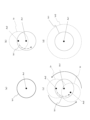
- 2 is a diagram for explaining a mechanism for expanding the visual field range or irradiation range in the optical fiber 100 shown in FIG. 1 .
- FIG. 2 is a diagram showing a jig for rotating the optical fiber 100 shown in FIG. 1 .
- FIG. 3 is a diagram showing an endoscope system 1000 including the optical fiber 100 shown in FIG. 2 .
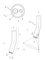
- 5A and 5B are diagrams showing the structure of an endoscope tube 200 according to a second embodiment of the present invention.
- the present invention aims to provide an optical fiber capable of transmitting images and light, which can easily expand the field of view or irradiation range without being restricted by the material used while avoiding an increase in size, and which can be easily inserted into curved parts of lumens such as those of the digestive system and respiratory system, or curved parts of piping in mechanical equipment.
- An optical fiber, A body portion and a tip portion The above problem is solved by providing an optical fiber whose tip is bent in advance relative to the main body.
- the tip portion is bent in advance relative to the main body portion, so that the end face of the tip portion (i.e., the light entrance surface or light exit surface of the optical fiber) faces in a direction that is inclined relative to the direction along the axis of the main body portion, and therefore, by rotating the main body portion about its axis, the end face of the tip portion rotates about the axis of the main body portion.
- the end face of the tip portion i.e., the light entrance surface or light exit surface of the optical fiber
- the end face of the tip portion rotates about the axis of the main body portion.
- the tip of the optical fiber of the present invention is pre-bent relative to the main body, there are no other limitations on its configuration.
- the bending angle is set so that the field of view and irradiation range centered on the axis of the tip include the area along the axis of the main body.
- the area around the front area in the field of view and irradiation range without losing the area along the axis of the main body (also called the front area) from the field of view and irradiation range, and the positional relationship between the expanded field of view and irradiation range and the front area (i.e. the area in front when the optical fiber is advanced) can be easily recognized.
- it becomes easier to analyze the image information transmitted from the optical fiber and it becomes possible to accurately apply illumination light, and even laser light for treatment or excitation, to the target object, preventing damage to the inside of the digestive organs, etc.
- the bending angle does not have to be set so that the field of view or irradiation range centered on the axis of the tip includes the area along the axis of the main body.
- the optical fiber has a structure in which multiple optical fiber bodies (i.e., optical fiber strands) consisting of a core portion as a core material and an outer cladding portion are bundled together.
- optical fiber bodies i.e., optical fiber strands
- the field of view or irradiation range can be expanded as an image guide portion that transmits images or a light guide portion that transmits illumination light.
- the optical fiber of the present invention also includes an image guide section for transmitting an image, and when the image guide section is provided on one side of the axis of the main body section, it is preferable that the tip section is bent in advance toward the side where the image guide section is located with respect to the axis of the main body section. This is because, in the optical fiber, when the tip section is bent toward the image guide section side where the image is acquired, an image of an area along a direction more inclined with respect to the axis of the main body section can be included in the field of view, and the field of view of the image guide section can be expanded more than when the tip section is bent toward the opposite side of the image guide section.
- a laser irradiation section for irradiating laser light may be provided instead of the image guide section.
- This laser irradiation section is a laser guide section for transmitting laser light, and is generally composed of an optical fiber strand (single strand). However, if the structure is composed of multiple optical fiber strands, it is possible to expand the irradiation range of the laser light by increasing the number of optical fiber strands.
- this laser guide section may be, for example, a treatment laser irradiation section for cauterizing the affected area, or an excitation laser irradiation section for exciting a fluorescent drug.
- a light guide section may be provided instead of the laser guide section.
- the light guide section transmits the illumination light, making it possible to expand the irradiation range of the illumination light.
- the bending angle between the axis of the tip and the axis of the main body is set according to the numerical aperture of the optical fiber.
- the numerical aperture of the optical fiber is large, it is possible to take in light from a direction more inclined with respect to the axis of the main body, and therefore by setting the bending angle according to the numerical aperture of the optical fiber, it is possible to set the bending angle of the tip part relative to the main body part just enough so that the front area does not fall outside the field of view, and the field of view can be expanded efficiently.
- the angle (bending angle) between the axis of the tip portion and the axis of the main body portion is set to be about 17 degrees to about 64 degrees (preferably about 6 degrees to about 21 degrees) when the numerical aperture of the optical fiber is about 0.3 to about 0.9, or about 13 degrees (preferably about 4 degrees) when the numerical aperture of the optical fiber is about 0.22. If the bending angle is too small, the selectivity for the shape of the inside of the digestive organs into which the optical fiber is inserted decreases, and the optical fiber is more likely to hit tissue.
- the optical fiber of the present invention is characterized by setting the bending angle so that the field of view or irradiation range centered on the axis of the tip includes the area along the axis of the main body.
- the optical fiber of the present invention is used in an endoscope tube.
- the flexible endoscopic tube for use in the endoscope is equipped with the optical fiber described above.
- the endoscope tube may have one optical fiber or may have multiple optical fibers.
- one of the multiple optical fibers may have an image guide section that transmits an image
- another of the multiple optical fibers may have a laser irradiation section that irradiates laser light (laser guide section that transmits laser light).
- laser guide section that transmits laser light
- the endoscope tube may also include a plurality of optical fibers, one of which may include an image guide section for transmitting an image, and another of which may include a light guide section for transmitting illumination light.
- the tip of at least one of the optical fibers is bent toward the side where the image guide section is located with respect to the axis of the main body. This is because, as described above, the range (field of view) for acquiring image information is further expanded. It is also preferable that the tip of the endoscope tube itself, in which the optical fibers are provided, is bent toward the side where the image guide section is located with respect to the main body.
- optical fiber structure of the present invention (structure in which the tip is bent relative to the main body) can also be applied to endoscopic tubes that are flexible enough for use in endoscopes and do not have optical fibers.
- the tube has a main body and a tip, the tip is equipped with a camera mounted on one side of its axis, and the tip is bent toward the side where the camera is located, so there are no other limitations on the configuration.
- optical fiber strand In this specification, the terms optical fiber strand, fiber bundle, image guide, light guide, laser guide, and fiberscope are defined as follows, and optical fiber is a general term for these, and refers to a fiber-like optical transmission medium through which light propagates.
- Optical fiber strand A single strand consisting of a core and an outer cladding.
- Image guide also called image guide section
- Optical fiber generally a fiber bundle
- Light guide also called light guide section
- Optical fiber generally a fiber bundle
- illumination light light from a light source such as a xenon lamp or LED
- Laser guide also called the laser guide section or laser irradiation section: An optical fiber that transmits the laser light used for treatment, excitation, etc.
- This laser guide is generally composed of a single optical fiber strand, but may also be composed of multiple optical fiber strands.
- the optical fiber 100 of this embodiment 1 has a main body (also called optical fiber main body) 110 and a tip (also called optical fiber tip) 120, and the optical fiber tip 120 is pre-bent with respect to the optical fiber main body 110.
- the pre-bent bending angle K1 is set so that the light receiving range (field of view range) Vr centered on the axis Ax2 of the optical fiber tip 120 includes an area along the axis Ax1 of the optical fiber main body 110, as shown in FIG. 1(b).
- the optical fiber 100 has a structure (fiber bundle) in which multiple optical fiber bodies (optical fiber strands) consisting of a core portion as a core material and a cladding portion on the outer side of the core portion are bundled together.
- FIG. 2 shows an example of a specific structure of the optical fiber 100 shown in FIG. 1, where FIG. 2(a) shows the image guide section 100a and light guide section 100b included in the optical fiber 100, and FIG. 2(b) specifically shows the cross-sectional structure taken along line IIa-IIa in FIG. 2(a). Also, FIG. 2(c) specifically shows a cross-sectional structure different from that in FIG. 2(b).
- the optical fiber 100 includes an image guide section 100a that transmits an image, and a light guide section 100b that transmits illumination light from a light source (not shown).
- a laser guide section (not shown), which is a laser irradiation section that irradiates laser light, may be included between the multiple optical fiber strands 101b that make up the light guide section 100b.
- the image guide section 100a is provided on one side of the axis Ax1 of the optical fiber main body section 110, and the optical fiber tip section 120 is bent in advance toward the side where the image guide section 100a is located with respect to the axis Ax1 of the optical fiber main body section 110 ( Figure 2(a)).
- This optical fiber 100 is configured so that the bending angle (K1) (see FIG. 1(b)) between the axis Ax1 of the optical fiber main body 110 and the axis Ax2 of the optical fiber tip 120 is set according to the numerical aperture (NA) of the optical fiber 100, and specifically, is set based on the following formula (1):
- K1 ⁇ arcsin NA...(1) Preferably, the relationship between the bending angle (K1) and the numerical aperture (NA) satisfies the following formula (2).
- the reason for this is that, as described above, the bending angle (K1) is practically required in the axial direction of the optical fiber. This is because the light intensity and optical performance can be obtained. K1 ⁇ (arcsin NA) / 3 ... (2)
- the numerical aperture of the image guide portion 100a is adopted as the numerical aperture of the optical fiber 100.
- the numerical aperture of the optical fiber 100 is approximately 0.22, and accordingly, the angle K1 between the axis Ax2 of the optical fiber tip 120 and the axis Ax1 of the optical fiber main body 110 is set to approximately 13 degrees (preferably approximately 4 degrees). However, if the numerical aperture is different, the angle K1 also differs, and when the numerical aperture of the optical fiber is approximately 0.3 to approximately 0.9, it is set to approximately 17 degrees to approximately 64 degrees (preferably approximately 6 degrees to approximately 21 degrees).
- the image guide section 100a constituting the optical fiber 100 has a structure in which multiple core wires 101a, each bundled to form a pixel, are embedded in a cladding medium 102a and covered with a coating layer 103a, and is housed in a housing tube 100d, which forms the outer wall of the optical fiber 100, at a position shifted to one side with respect to the axis of the optical fiber 100.
- the image guide section 100a is not limited to a structure in which multiple core wires 101a are embedded in a cladding medium 102a, but may also have a structure (fiber bundle section) in which optical fiber strands 101b consisting of a core and a cladding are bundled.
- the light guide section 100b that constitutes the optical fiber 100 is a bundle (fiber bundle section) of optical fiber strands 101b that are made up of a core and a cladding, and is housed in an area other than the area occupied by the image guide section 100a in the housing tube 100d.
- the location where the light guide section 100b is housed may be provided with a treatment or excitation laser irradiation section that irradiates treatment or excitation laser light to cauterize an affected area or excite a drug.
- This laser irradiation section is generally a laser guide section that transmits laser light and is made up of a single wire (optical fiber strand), but may also be a laser guide section made up of multiple optical fiber strands.
- Figure 3 is a diagram for explaining how to use the optical fiber 100 shown in Figure 1, where Figure 3(a) shows the field of view (observation area) Vr1 when the tip of the optical fiber 100 is not bent, Figure 3(b) shows the field of view (observation area) Vr when the tip of the optical fiber 100 is bent, superimposed on the field of view Vr1 when the tip is not bent, Figure 3(c) shows how the field of view (observation area) or irradiation range Vr moves as the optical fiber 100 rotates around the main body axis Ax1, and Figure 3(d) shows the observable field of view or irradiation range Vr2 when the optical fiber 100 with a bent tip is rotated once around the axis Ax1 of the main body 110.
- the field of view Vr2 of the optical fiber 100 in which the optical fiber tip 120 is bent relative to the optical fiber main body 110 can be a wide field of view that is an enlarged version of the field of view Vr1 of an optical fiber in which the optical fiber tip 120 is not bent relative to the optical fiber main body 110 ( Figure 3 (d)).
- Optical fiber rotating jig Next, a jig for rotating the optical fiber 100 will be described.
- FIG. 4 shows a jig for rotating the optical fiber 100 of the present invention.
- Figure 4 shows an example of a jig for rotating the optical fiber of the present invention, the tip of which is bent in advance.
- the optical fiber 100 is inserted into the guide tube 300 in a state in which it can move freely within the tube.
- a rotation operation piece 310 is fixed to the optical fiber 100, and an operator can rotate the optical fiber by holding the rotation operation piece 310 in his/her hand and rotating the rotation operation piece 310.
- the guide tube 300 and the rotation operation piece 310 may have engagement parts 300a, 310b that enable them to engage with each other. In this case, the operator can grasp the rotation operation part 310 to move the optical fiber 100 in the axial direction, and engage the engagement parts 300a and 310b at a predetermined position to rotate the guide tube 300.
- FIG. 4(b) shows a rotation operation piece 400 having a pair of gripping parts 402 and an optical fiber fixing part 401 disposed between them.
- the pair of gripping parts 402 are folded so that they overlap, and the overlapping part becomes a handle for rotation operation.
- the optical fiber 100 can be rotated by holding this handle, moving the optical fiber, releasing it, returning the jig, and repeating the process, and by gripping and rotating it at a predetermined position.
- the optical fiber fixing part 401 may be provided with multiple protrusions, and the optical fiber 100 may be inserted between the multiple protrusions to improve the fixing force of the optical fiber.
- the rotating operation piece 500 may be composed of a pair of upper and lower optical fiber fixing pieces 501, 502.
- the optical fiber is moved by holding the pair of optical fiber fixing pieces 501, 502, and the process of releasing and returning the jig is repeated, and the optical fiber is gripped and rotated at a predetermined position.
- Each of the pair of optical fiber fixing pieces 501, 502 has multiple protrusions. By inserting the optical fiber 100 between these protrusions, it is possible to improve the fixing force of the optical fiber 100. Note that the multiple protrusions may be provided on only one of the pair of optical fiber fixing pieces.
- the optical fiber 100 of the first embodiment has a main body 110 and a tip 120, and the tip 120 is bent in advance relative to the main body 110, so that it is possible to easily expand the field of view and the irradiation range without being restricted by the material used, while avoiding the need to increase the size of the optical fiber capable of transmitting images, such as by increasing the diameter of the optical fiber.
- the tip since the tip is bent, it is also possible to improve the ease of insertion into bent or curved digestive organs such as the intestines and stomach, respiratory organs such as the lungs and trachea, or piping of mechanical equipment.
- the bending angle K1 which is bent in advance, is set so that the light receiving range (field of view) or irradiation range Vr centered on the axis Ax2 of the tip 120 includes an area along the axis Ax1 of the main body 110. This makes it possible to include the area around the frontal area in the field of view or irradiation range without losing the area along the axis Ax1 of the main body 110 (also called the frontal area) from the field of view or irradiation range Vr.
- the positional relationship between the expanded field of view or irradiation range and the frontal area can be easily recognized, facilitating the analysis of image information transmitted from the optical fiber, and enabling accurate application of illumination light or laser light for treatment or excitation to the target object, preventing damage to the digestive or respiratory tract, etc.
- the optical fiber tip section 120 is bent in advance to the side where the image guide section 110a or the light irradiation section is located with respect to the axis Ax1 of the optical fiber main body 110, so that it is possible to capture an image of an area along a direction more inclined with respect to the axis Ax1 of the optical fiber main body 110, or to irradiate light such as laser light or illumination light to an area along a direction more inclined with respect to the axis Ax1 of the optical fiber main body 110, compared to when the optical fiber tip section 120 is bent on the opposite side to the image guide section 100a or the light irradiation section.
- the image guide section 100a that transmits an image or the light irradiation section (light guide section 100b and/or laser irradiation section) that irradiates light
- the bending angle K1 between the axis Ax2 of the optical fiber tip 120 and the axis Ax1 of the optical fiber main body 110 is set according to the numerical aperture of the optical fiber 100, so that the bending angle K1 of the optical fiber tip 120 that can expand the field of view or irradiation range without causing the front area to fall outside the field of view or irradiation range can be easily determined.
- the optical fiber 100 of embodiment 1 may be used in an endoscope tube that has flexibility for use in an endoscope, in which case the endoscope tube includes the optical fiber of the present invention described above.
- the endoscope tube may have one optical fiber or may have multiple optical fibers.
- one of the multiple optical fibers may have an image guide section that transmits an image
- another of the multiple optical fibers may have a light irradiation section that irradiates light (e.g., an illumination light irradiation section, a laser irradiation section).
- a light irradiation section that irradiates light
- the multiple optical fibers may be configured to have an image guide section, a light guide section, and a laser guide section, or may include other optical fibers.
- FIG. 5 is a diagram showing an endoscope system 1000 including the optical fiber 100 shown in FIG. 2.
- This endoscope system 1000 has an optical fiber 100 and a system main body 40 that processes optical signals from the optical fiber 100.
- the tip portion 10 of the optical fiber 100 is designed to be inserted into an endoscope tube (not shown).
- the endoscope tube may be provided with a hollow tube for inserting a biopsy forceps or a treatment fiber. Note that the biopsy forceps and the treatment fiber may be inserted into a single hollow tube, or each may be inserted into a separate hollow tube.
- the objects to be inserted into the hollow tube may be various devices such as a thermocouple for measuring the temperature of biological tissue and a biopsy needle for collecting biological tissue.
- the Gaussian-distributed laser light or illumination light output from the optical fiber of this invention is distributed uniformly, making it possible to suppress localized temperature rises in biological tissue.
- thermocouple In conventional endoscopes that do not have a bent portion, it is difficult to bring a thermocouple into contact with the wall of a tubular tissue such as a trachea. However, by rotating the tube (fiber) with a bent tip of the present invention, it is possible to place a thermocouple on the desired wall of the tubular tissue.
- the laser optical fiber 100 is a fiberscope having an image guide section 100a that transmits an image, a light guide section 100b that transmits illumination light, and a laser guide section 100c that transmits laser light, and the multiple optical fiber strands that make up the tip section 10 of each guide section are housed integrally in a single housing tube 100d (see FIG. 2(a)).
- This tip section 10 includes a tip section 120 and the remaining main body section 110, and the tip section 120 is bent relative to the main body section 110.
- the multiple optical fiber strands housed in one of the housing tubes 100d are grouped and extracted into those constituting the image guide section 100a, those constituting the light guide section 100b, and those constituting the laser guide section 100c, and the extracted optical fiber strands are connected to the corresponding image guide connector 11a, light guide connector 11b, and laser guide connector 11c.
- the system main body 40 has an imaging device 40a that captures an image from the image guide section 100a, an illumination light source 40b that outputs illumination light to the light guide section 100b, a laser light source 40c that outputs laser light to the laser guide section 100c, and a control device 40d that controls the imaging device 40a, the illumination light source 40b, and the laser light source 40c in response to the operation of the operator.
- the imaging device 40a is connected to the image guide section 100a via the image guide connector 11a
- the illumination light source 40b is connected to the light guide section 100b via the light guide connector 11b
- the laser light source 40c is connected to the laser guide section 100c via the laser guide connector 11c.
- a display device 41 is also connected to the system main body 40, and is configured to display the operation contents by the operator, images captured by the imaging device 40a, etc.
- the structure in which the tip 120 of the optical fiber 100 of embodiment 1 is bent relative to its main body 110 can also be applied to flexible tubes for use in endoscopes, particularly those that do not have optical fibers, and such an endoscope tube will be described below as embodiment 2 of the present invention.
- the tube has a main body and a tip, the tip is equipped with a camera mounted on one side of its axis, and the tip is bent toward the side where the camera is located, so there are no other limitations on the configuration.
- This endoscope tube 200 is a flexible tube for use in an endoscope, and as shown in FIG. 6(a), has a main body portion (also called the tube main body portion) 210 and a tip portion (also called the tube tip portion) 220.
- the tube tip 220 has a camera unit 200a provided on one side of the axis Bx2 and a light emitting unit 200b provided on the other side of the axis Bx2, and the tube tip 220 is bent towards the side where the camera unit 200a is located.
- the bending angle (K2) is the angle between the axis Bx2 of the tube tip 220 and the axis Bx1 of the tube main body 210, and is set based on the numerical aperture (NA2) of the optical system of the camera 200a.
- the bending angle K2 can be calculated from the numerical aperture NA2 based on the above formula (1) or formula (2).
- the endoscope tube 200 of embodiment 2 of the present invention which has such a configuration, makes it possible to easily expand the field of view of the camera unit while avoiding an increase in size of the camera unit that captures images.
- the field of view of the camera unit is expanded, but by making the camera unit a light irradiation unit that irradiates illumination light or treatment light, it is possible to easily expand the irradiation range without being restricted by the materials used while avoiding an increase in size.
- the present invention is useful in the field of optical fibers as it can easily expand the field of view and irradiation range without being restricted by the materials used while avoiding the need for large optical fibers, and it also maintains the ease of insertion into curved parts of lumens such as those of the digestive system and respiratory system, or into curved parts of piping in mechanical equipment.
Landscapes
- Health & Medical Sciences (AREA)
- Life Sciences & Earth Sciences (AREA)
- Physics & Mathematics (AREA)
- Surgery (AREA)
- Optics & Photonics (AREA)
- Biomedical Technology (AREA)
- Medical Informatics (AREA)
- Radiology & Medical Imaging (AREA)
- Nuclear Medicine, Radiotherapy & Molecular Imaging (AREA)
- Engineering & Computer Science (AREA)
- Biophysics (AREA)
- Heart & Thoracic Surgery (AREA)
- Pathology (AREA)
- Molecular Biology (AREA)
- Animal Behavior & Ethology (AREA)
- General Health & Medical Sciences (AREA)
- Public Health (AREA)
- Veterinary Medicine (AREA)
- General Physics & Mathematics (AREA)
- Endoscopes (AREA)
Priority Applications (2)
| Application Number | Priority Date | Filing Date | Title |
|---|---|---|---|
| JP2024552491A JP7721014B2 (ja) | 2023-07-12 | 2024-04-25 | 光ファイバーおよび内視鏡用チューブ |
| JP2025126309A JP2025157565A (ja) | 2023-07-12 | 2025-07-29 | 光ファイバーおよび内視鏡用チューブ |
Applications Claiming Priority (2)
| Application Number | Priority Date | Filing Date | Title |
|---|---|---|---|
| JP2023-114610 | 2023-07-12 | ||
| JP2023114610 | 2023-07-12 |
Publications (1)
| Publication Number | Publication Date |
|---|---|
| WO2025013377A1 true WO2025013377A1 (ja) | 2025-01-16 |
Family
ID=94214905
Family Applications (1)
| Application Number | Title | Priority Date | Filing Date |
|---|---|---|---|
| PCT/JP2024/016243 Pending WO2025013377A1 (ja) | 2023-07-12 | 2024-04-25 | 光ファイバーおよび内視鏡用チューブ |
Country Status (2)
| Country | Link |
|---|---|
| JP (2) | JP7721014B2 (https=) |
| WO (1) | WO2025013377A1 (https=) |
Families Citing this family (1)
| Publication number | Priority date | Publication date | Assignee | Title |
|---|---|---|---|---|
| JP2015143843A (ja) * | 2013-12-24 | 2015-08-06 | 株式会社半導体エネルギー研究所 | 電子機器 |
Citations (10)
| Publication number | Priority date | Publication date | Assignee | Title |
|---|---|---|---|---|
| JPS63277030A (ja) * | 1987-05-09 | 1988-11-15 | Mitsubishi Cable Ind Ltd | カテ−テル形ファイバスコ−プ |
| JPH01172801U (https=) * | 1988-05-28 | 1989-12-07 | ||
| JPH0220501U (https=) * | 1988-07-25 | 1990-02-09 | ||
| JPH0690892A (ja) * | 1992-09-01 | 1994-04-05 | Citation Medical Corp | 内視鏡のスコープ組立体 |
| JP2004198912A (ja) * | 2002-12-20 | 2004-07-15 | Olympus Corp | 走査型光学系 |
| US20160367119A1 (en) * | 2015-02-23 | 2016-12-22 | Xiaolong OuYang | Handheld surgical endoscope |
| JP2019171021A (ja) * | 2018-01-25 | 2019-10-10 | キヤノン ユーエスエイ, インコーポレイテッドCanon U.S.A., Inc | 内視鏡における光学ファイバの配置 |
| JP2020036884A (ja) * | 2018-08-29 | 2020-03-12 | 株式会社Okファイバーテクノロジー | 挿入性の良いファイバースコープ |
| WO2021039690A1 (ja) * | 2019-08-28 | 2021-03-04 | Hoya株式会社 | 内視鏡 |
| JP2022048866A (ja) * | 2020-09-15 | 2022-03-28 | Hoya株式会社 | 内視鏡用プロセッサ及び内視鏡システム |
-
2024
- 2024-04-25 WO PCT/JP2024/016243 patent/WO2025013377A1/ja active Pending
- 2024-04-25 JP JP2024552491A patent/JP7721014B2/ja active Active
-
2025
- 2025-07-29 JP JP2025126309A patent/JP2025157565A/ja active Pending
Patent Citations (10)
| Publication number | Priority date | Publication date | Assignee | Title |
|---|---|---|---|---|
| JPS63277030A (ja) * | 1987-05-09 | 1988-11-15 | Mitsubishi Cable Ind Ltd | カテ−テル形ファイバスコ−プ |
| JPH01172801U (https=) * | 1988-05-28 | 1989-12-07 | ||
| JPH0220501U (https=) * | 1988-07-25 | 1990-02-09 | ||
| JPH0690892A (ja) * | 1992-09-01 | 1994-04-05 | Citation Medical Corp | 内視鏡のスコープ組立体 |
| JP2004198912A (ja) * | 2002-12-20 | 2004-07-15 | Olympus Corp | 走査型光学系 |
| US20160367119A1 (en) * | 2015-02-23 | 2016-12-22 | Xiaolong OuYang | Handheld surgical endoscope |
| JP2019171021A (ja) * | 2018-01-25 | 2019-10-10 | キヤノン ユーエスエイ, インコーポレイテッドCanon U.S.A., Inc | 内視鏡における光学ファイバの配置 |
| JP2020036884A (ja) * | 2018-08-29 | 2020-03-12 | 株式会社Okファイバーテクノロジー | 挿入性の良いファイバースコープ |
| WO2021039690A1 (ja) * | 2019-08-28 | 2021-03-04 | Hoya株式会社 | 内視鏡 |
| JP2022048866A (ja) * | 2020-09-15 | 2022-03-28 | Hoya株式会社 | 内視鏡用プロセッサ及び内視鏡システム |
Also Published As
| Publication number | Publication date |
|---|---|
| JP2025157565A (ja) | 2025-10-15 |
| JPWO2025013377A1 (https=) | 2025-01-16 |
| JP7721014B2 (ja) | 2025-08-08 |
Similar Documents
| Publication | Publication Date | Title |
|---|---|---|
| US10786205B2 (en) | Sensing catheter emitting radiant energy | |
| JP4691361B2 (ja) | 取り外し可能な偏向デバイスを備える内視鏡画像化システム | |
| CN109068970B (zh) | 内窥镜装置 | |
| JP7302816B2 (ja) | 挿入性の良いファイバースコープ | |
| JP2022509462A (ja) | 医療器具用の挿入ユニット及びその挿管システム | |
| US20190099612A1 (en) | Endoscope | |
| JP7283778B2 (ja) | イメージングシステム及び方法 | |
| US6506150B1 (en) | Self-retaining endoscope | |
| JP2023524078A (ja) | 遠隔病原菌除菌 | |
| TW200526167A (en) | Optical device for viewing of cavernous and/or inaccessible spaces | |
| JP2025157565A (ja) | 光ファイバーおよび内視鏡用チューブ | |
| JP7336119B1 (ja) | 光照射デバイスおよび光照射システム | |
| JPH1026709A (ja) | レーザ側方照射器 | |
| CN118382389A (zh) | 用于基于激光的医疗装置照明的系统和方法 | |
| US20250025030A1 (en) | Endoscope with optical imaging system | |
| JP6498028B2 (ja) | 内視鏡用光線力学的治療装置 | |
| JPWO2025013377A5 (https=) | ||
| KR20180074858A (ko) | 플라스틱 광섬유를 포함하는 분리형 일회용 내시경 | |
| CN109316159B (zh) | 一种内窥镜的照明装置 | |
| JP7546258B2 (ja) | 挿入性の良いファイバースコープ | |
| WO2021176570A1 (ja) | 内視鏡システム、および内視鏡の操作方法 | |
| WO2020070862A1 (ja) | 内視鏡の先端部 | |
| JPH01293312A (ja) | 繊維光学システム | |
| US20260012693A1 (en) | Endoscope with diffractive light shaping structure | |
| JP2005296379A (ja) | 内視鏡用処置具及び内視鏡用処置具システム |
Legal Events
| Date | Code | Title | Description |
|---|---|---|---|
| WWE | Wipo information: entry into national phase |
Ref document number: 2024552491 Country of ref document: JP |
|
| 121 | Ep: the epo has been informed by wipo that ep was designated in this application |
Ref document number: 24839275 Country of ref document: EP Kind code of ref document: A1 |
|
| NENP | Non-entry into the national phase |
Ref country code: DE |