US10786205B2 - Sensing catheter emitting radiant energy - Google Patents
Sensing catheter emitting radiant energy Download PDFInfo
- Publication number
- US10786205B2 US10786205B2 US14/473,812 US201414473812A US10786205B2 US 10786205 B2 US10786205 B2 US 10786205B2 US 201414473812 A US201414473812 A US 201414473812A US 10786205 B2 US10786205 B2 US 10786205B2
- Authority
- US
- United States
- Prior art keywords
- catheter
- radiant energy
- passage
- body lumen
- fluid
- Prior art date
- Legal status (The legal status is an assumption and is not a legal conclusion. Google has not performed a legal analysis and makes no representation as to the accuracy of the status listed.)
- Active, expires
Links
- 239000012530 fluid Substances 0.000 claims abstract description 57
- 239000000835 fiber Substances 0.000 claims description 31
- 238000003780 insertion Methods 0.000 claims description 14
- 230000037431 insertion Effects 0.000 claims description 14
- 238000004458 analytical method Methods 0.000 claims description 6
- 230000005670 electromagnetic radiation Effects 0.000 claims description 5
- 230000035876 healing Effects 0.000 claims description 5
- 238000012921 fluorescence analysis Methods 0.000 claims description 4
- 230000000007 visual effect Effects 0.000 claims description 4
- 230000002685 pulmonary effect Effects 0.000 claims description 3
- 238000010183 spectrum analysis Methods 0.000 claims description 3
- 238000011179 visual inspection Methods 0.000 claims description 3
- 238000001839 endoscopy Methods 0.000 claims 2
- 230000005855 radiation Effects 0.000 abstract description 4
- 238000005286 illumination Methods 0.000 description 45
- 238000011282 treatment Methods 0.000 description 35
- 238000003384 imaging method Methods 0.000 description 20
- 239000007788 liquid Substances 0.000 description 12
- 230000008901 benefit Effects 0.000 description 5
- 239000000463 material Substances 0.000 description 4
- 238000000034 method Methods 0.000 description 4
- 230000002485 urinary effect Effects 0.000 description 4
- 238000013461 design Methods 0.000 description 3
- 230000002262 irrigation Effects 0.000 description 3
- 238000003973 irrigation Methods 0.000 description 3
- 230000000712 assembly Effects 0.000 description 2
- 238000000429 assembly Methods 0.000 description 2
- 238000003745 diagnosis Methods 0.000 description 2
- 238000010521 absorption reaction Methods 0.000 description 1
- 210000003484 anatomy Anatomy 0.000 description 1
- 230000000845 anti-microbial effect Effects 0.000 description 1
- 230000004888 barrier function Effects 0.000 description 1
- 230000009286 beneficial effect Effects 0.000 description 1
- 230000005540 biological transmission Effects 0.000 description 1
- 238000006243 chemical reaction Methods 0.000 description 1
- 230000001427 coherent effect Effects 0.000 description 1
- 239000004020 conductor Substances 0.000 description 1
- 238000011161 development Methods 0.000 description 1
- 230000018109 developmental process Effects 0.000 description 1
- 238000010586 diagram Methods 0.000 description 1
- 239000003814 drug Substances 0.000 description 1
- 229940079593 drug Drugs 0.000 description 1
- 230000009977 dual effect Effects 0.000 description 1
- 230000007774 longterm Effects 0.000 description 1
- 230000013011 mating Effects 0.000 description 1
- 239000000203 mixture Substances 0.000 description 1
- 239000013307 optical fiber Substances 0.000 description 1
- 238000004806 packaging method and process Methods 0.000 description 1
- 230000002186 photoactivation Effects 0.000 description 1
- 238000001126 phototherapy Methods 0.000 description 1
- 230000003595 spectral effect Effects 0.000 description 1
- 230000001954 sterilising effect Effects 0.000 description 1
- 238000004659 sterilization and disinfection Methods 0.000 description 1
- 239000003351 stiffener Substances 0.000 description 1
- 238000001356 surgical procedure Methods 0.000 description 1
- 238000001931 thermography Methods 0.000 description 1
- 230000000472 traumatic effect Effects 0.000 description 1
- 210000003708 urethra Anatomy 0.000 description 1
- 238000012800 visualization Methods 0.000 description 1
Images


Classifications
-
- A—HUMAN NECESSITIES
- A61—MEDICAL OR VETERINARY SCIENCE; HYGIENE
- A61B—DIAGNOSIS; SURGERY; IDENTIFICATION
- A61B5/00—Measuring for diagnostic purposes; Identification of persons
- A61B5/68—Arrangements of detecting, measuring or recording means, e.g. sensors, in relation to patient
- A61B5/6846—Arrangements of detecting, measuring or recording means, e.g. sensors, in relation to patient specially adapted to be brought in contact with an internal body part, i.e. invasive
- A61B5/6847—Arrangements of detecting, measuring or recording means, e.g. sensors, in relation to patient specially adapted to be brought in contact with an internal body part, i.e. invasive mounted on an invasive device
- A61B5/6852—Catheters
-
- A—HUMAN NECESSITIES
- A61—MEDICAL OR VETERINARY SCIENCE; HYGIENE
- A61B—DIAGNOSIS; SURGERY; IDENTIFICATION
- A61B1/00—Instruments for performing medical examinations of the interior of cavities or tubes of the body by visual or photographical inspection, e.g. endoscopes; Illuminating arrangements therefor
- A61B1/00064—Constructional details of the endoscope body
- A61B1/00071—Insertion part of the endoscope body
- A61B1/0008—Insertion part of the endoscope body characterised by distal tip features
- A61B1/00096—Optical elements
-
- A—HUMAN NECESSITIES
- A61—MEDICAL OR VETERINARY SCIENCE; HYGIENE
- A61B—DIAGNOSIS; SURGERY; IDENTIFICATION
- A61B1/00—Instruments for performing medical examinations of the interior of cavities or tubes of the body by visual or photographical inspection, e.g. endoscopes; Illuminating arrangements therefor
- A61B1/00131—Accessories for endoscopes
- A61B1/00135—Oversleeves mounted on the endoscope prior to insertion
-
- A—HUMAN NECESSITIES
- A61—MEDICAL OR VETERINARY SCIENCE; HYGIENE
- A61B—DIAGNOSIS; SURGERY; IDENTIFICATION
- A61B1/00—Instruments for performing medical examinations of the interior of cavities or tubes of the body by visual or photographical inspection, e.g. endoscopes; Illuminating arrangements therefor
- A61B1/012—Instruments for performing medical examinations of the interior of cavities or tubes of the body by visual or photographical inspection, e.g. endoscopes; Illuminating arrangements therefor characterised by internal passages or accessories therefor
- A61B1/015—Control of fluid supply or evacuation
-
- A—HUMAN NECESSITIES
- A61—MEDICAL OR VETERINARY SCIENCE; HYGIENE
- A61B—DIAGNOSIS; SURGERY; IDENTIFICATION
- A61B1/00—Instruments for performing medical examinations of the interior of cavities or tubes of the body by visual or photographical inspection, e.g. endoscopes; Illuminating arrangements therefor
- A61B1/04—Instruments for performing medical examinations of the interior of cavities or tubes of the body by visual or photographical inspection, e.g. endoscopes; Illuminating arrangements therefor combined with photographic or television appliances
- A61B1/05—Instruments for performing medical examinations of the interior of cavities or tubes of the body by visual or photographical inspection, e.g. endoscopes; Illuminating arrangements therefor combined with photographic or television appliances characterised by the image sensor, e.g. camera, being in the distal end portion
-
- A—HUMAN NECESSITIES
- A61—MEDICAL OR VETERINARY SCIENCE; HYGIENE
- A61B—DIAGNOSIS; SURGERY; IDENTIFICATION
- A61B1/00—Instruments for performing medical examinations of the interior of cavities or tubes of the body by visual or photographical inspection, e.g. endoscopes; Illuminating arrangements therefor
- A61B1/06—Instruments for performing medical examinations of the interior of cavities or tubes of the body by visual or photographical inspection, e.g. endoscopes; Illuminating arrangements therefor with illuminating arrangements
- A61B1/0607—Instruments for performing medical examinations of the interior of cavities or tubes of the body by visual or photographical inspection, e.g. endoscopes; Illuminating arrangements therefor with illuminating arrangements for annular illumination
-
- A—HUMAN NECESSITIES
- A61—MEDICAL OR VETERINARY SCIENCE; HYGIENE
- A61B—DIAGNOSIS; SURGERY; IDENTIFICATION
- A61B1/00—Instruments for performing medical examinations of the interior of cavities or tubes of the body by visual or photographical inspection, e.g. endoscopes; Illuminating arrangements therefor
- A61B1/06—Instruments for performing medical examinations of the interior of cavities or tubes of the body by visual or photographical inspection, e.g. endoscopes; Illuminating arrangements therefor with illuminating arrangements
- A61B1/0661—Endoscope light sources
- A61B1/0676—Endoscope light sources at distal tip of an endoscope
-
- A—HUMAN NECESSITIES
- A61—MEDICAL OR VETERINARY SCIENCE; HYGIENE
- A61B—DIAGNOSIS; SURGERY; IDENTIFICATION
- A61B1/00—Instruments for performing medical examinations of the interior of cavities or tubes of the body by visual or photographical inspection, e.g. endoscopes; Illuminating arrangements therefor
- A61B1/06—Instruments for performing medical examinations of the interior of cavities or tubes of the body by visual or photographical inspection, e.g. endoscopes; Illuminating arrangements therefor with illuminating arrangements
- A61B1/0661—Endoscope light sources
- A61B1/0684—Endoscope light sources using light emitting diodes [LED]
-
- A—HUMAN NECESSITIES
- A61—MEDICAL OR VETERINARY SCIENCE; HYGIENE
- A61B—DIAGNOSIS; SURGERY; IDENTIFICATION
- A61B1/00—Instruments for performing medical examinations of the interior of cavities or tubes of the body by visual or photographical inspection, e.g. endoscopes; Illuminating arrangements therefor
- A61B1/06—Instruments for performing medical examinations of the interior of cavities or tubes of the body by visual or photographical inspection, e.g. endoscopes; Illuminating arrangements therefor with illuminating arrangements
- A61B1/07—Instruments for performing medical examinations of the interior of cavities or tubes of the body by visual or photographical inspection, e.g. endoscopes; Illuminating arrangements therefor with illuminating arrangements using light-conductive means, e.g. optical fibres
-
- A—HUMAN NECESSITIES
- A61—MEDICAL OR VETERINARY SCIENCE; HYGIENE
- A61B—DIAGNOSIS; SURGERY; IDENTIFICATION
- A61B1/00—Instruments for performing medical examinations of the interior of cavities or tubes of the body by visual or photographical inspection, e.g. endoscopes; Illuminating arrangements therefor
- A61B1/307—Instruments for performing medical examinations of the interior of cavities or tubes of the body by visual or photographical inspection, e.g. endoscopes; Illuminating arrangements therefor for the urinary organs, e.g. urethroscopes, cystoscopes
-
- A—HUMAN NECESSITIES
- A61—MEDICAL OR VETERINARY SCIENCE; HYGIENE
- A61B—DIAGNOSIS; SURGERY; IDENTIFICATION
- A61B18/00—Surgical instruments, devices or methods for transferring non-mechanical forms of energy to or from the body
- A61B18/18—Surgical instruments, devices or methods for transferring non-mechanical forms of energy to or from the body by applying electromagnetic radiation, e.g. microwaves
- A61B18/20—Surgical instruments, devices or methods for transferring non-mechanical forms of energy to or from the body by applying electromagnetic radiation, e.g. microwaves using laser
- A61B18/22—Surgical instruments, devices or methods for transferring non-mechanical forms of energy to or from the body by applying electromagnetic radiation, e.g. microwaves using laser the beam being directed along or through a flexible conduit, e.g. an optical fibre; Couplings or hand-pieces therefor
- A61B18/24—Surgical instruments, devices or methods for transferring non-mechanical forms of energy to or from the body by applying electromagnetic radiation, e.g. microwaves using laser the beam being directed along or through a flexible conduit, e.g. an optical fibre; Couplings or hand-pieces therefor with a catheter
-
- A—HUMAN NECESSITIES
- A61—MEDICAL OR VETERINARY SCIENCE; HYGIENE
- A61B—DIAGNOSIS; SURGERY; IDENTIFICATION
- A61B6/00—Apparatus for radiation diagnosis, e.g. combined with radiation therapy equipment
- A61B6/42—Apparatus for radiation diagnosis, e.g. combined with radiation therapy equipment with arrangements for detecting radiation specially adapted for radiation diagnosis
- A61B6/4208—Apparatus for radiation diagnosis, e.g. combined with radiation therapy equipment with arrangements for detecting radiation specially adapted for radiation diagnosis characterised by using a particular type of detector
- A61B6/425—Apparatus for radiation diagnosis, e.g. combined with radiation therapy equipment with arrangements for detecting radiation specially adapted for radiation diagnosis characterised by using a particular type of detector using detectors specially adapted to be used in the interior of the body
-
- A—HUMAN NECESSITIES
- A61—MEDICAL OR VETERINARY SCIENCE; HYGIENE
- A61M—DEVICES FOR INTRODUCING MEDIA INTO, OR ONTO, THE BODY; DEVICES FOR TRANSDUCING BODY MEDIA OR FOR TAKING MEDIA FROM THE BODY; DEVICES FOR PRODUCING OR ENDING SLEEP OR STUPOR
- A61M25/00—Catheters; Hollow probes
- A61M25/0021—Catheters; Hollow probes characterised by the form of the tubing
- A61M25/0023—Catheters; Hollow probes characterised by the form of the tubing by the form of the lumen, e.g. cross-section, variable diameter
- A61M25/0026—Multi-lumen catheters with stationary elements
- A61M25/003—Multi-lumen catheters with stationary elements characterized by features relating to least one lumen located at the distal part of the catheter, e.g. filters, plugs or valves
-
- A—HUMAN NECESSITIES
- A61—MEDICAL OR VETERINARY SCIENCE; HYGIENE
- A61N—ELECTROTHERAPY; MAGNETOTHERAPY; RADIATION THERAPY; ULTRASOUND THERAPY
- A61N5/00—Radiation therapy
- A61N5/02—Radiation therapy using microwaves
- A61N5/04—Radiators for near-field treatment
- A61N5/045—Radiators for near-field treatment specially adapted for treatment inside the body
-
- A—HUMAN NECESSITIES
- A61—MEDICAL OR VETERINARY SCIENCE; HYGIENE
- A61N—ELECTROTHERAPY; MAGNETOTHERAPY; RADIATION THERAPY; ULTRASOUND THERAPY
- A61N5/00—Radiation therapy
- A61N5/06—Radiation therapy using light
- A61N5/0601—Apparatus for use inside the body
-
- G—PHYSICS
- G02—OPTICS
- G02B—OPTICAL ELEMENTS, SYSTEMS OR APPARATUS
- G02B23/00—Telescopes, e.g. binoculars; Periscopes; Instruments for viewing the inside of hollow bodies; Viewfinders; Optical aiming or sighting devices
- G02B23/24—Instruments or systems for viewing the inside of hollow bodies, e.g. fibrescopes
- G02B23/2407—Optical details
- G02B23/2461—Illumination
-
- G—PHYSICS
- G02—OPTICS
- G02B—OPTICAL ELEMENTS, SYSTEMS OR APPARATUS
- G02B23/00—Telescopes, e.g. binoculars; Periscopes; Instruments for viewing the inside of hollow bodies; Viewfinders; Optical aiming or sighting devices
- G02B23/24—Instruments or systems for viewing the inside of hollow bodies, e.g. fibrescopes
- G02B23/2476—Non-optical details, e.g. housings, mountings, supports
- G02B23/2484—Arrangements in relation to a camera or imaging device
-
- A—HUMAN NECESSITIES
- A61—MEDICAL OR VETERINARY SCIENCE; HYGIENE
- A61B—DIAGNOSIS; SURGERY; IDENTIFICATION
- A61B18/00—Surgical instruments, devices or methods for transferring non-mechanical forms of energy to or from the body
- A61B18/04—Surgical instruments, devices or methods for transferring non-mechanical forms of energy to or from the body by heating
- A61B18/12—Surgical instruments, devices or methods for transferring non-mechanical forms of energy to or from the body by heating by passing a current through the tissue to be heated, e.g. high-frequency current
- A61B18/14—Probes or electrodes therefor
- A61B18/1492—Probes or electrodes therefor having a flexible, catheter-like structure, e.g. for heart ablation
-
- A—HUMAN NECESSITIES
- A61—MEDICAL OR VETERINARY SCIENCE; HYGIENE
- A61B—DIAGNOSIS; SURGERY; IDENTIFICATION
- A61B18/00—Surgical instruments, devices or methods for transferring non-mechanical forms of energy to or from the body
- A61B2018/00982—Surgical instruments, devices or methods for transferring non-mechanical forms of energy to or from the body combined with or comprising means for visual or photographic inspections inside the body, e.g. endoscopes
-
- A—HUMAN NECESSITIES
- A61—MEDICAL OR VETERINARY SCIENCE; HYGIENE
- A61B—DIAGNOSIS; SURGERY; IDENTIFICATION
- A61B18/00—Surgical instruments, devices or methods for transferring non-mechanical forms of energy to or from the body
- A61B18/18—Surgical instruments, devices or methods for transferring non-mechanical forms of energy to or from the body by applying electromagnetic radiation, e.g. microwaves
- A61B18/1815—Surgical instruments, devices or methods for transferring non-mechanical forms of energy to or from the body by applying electromagnetic radiation, e.g. microwaves using microwaves
- A61B2018/1861—Surgical instruments, devices or methods for transferring non-mechanical forms of energy to or from the body by applying electromagnetic radiation, e.g. microwaves using microwaves with an instrument inserted into a body lumen or cavity, e.g. a catheter
-
- A—HUMAN NECESSITIES
- A61—MEDICAL OR VETERINARY SCIENCE; HYGIENE
- A61B—DIAGNOSIS; SURGERY; IDENTIFICATION
- A61B18/00—Surgical instruments, devices or methods for transferring non-mechanical forms of energy to or from the body
- A61B18/18—Surgical instruments, devices or methods for transferring non-mechanical forms of energy to or from the body by applying electromagnetic radiation, e.g. microwaves
- A61B18/20—Surgical instruments, devices or methods for transferring non-mechanical forms of energy to or from the body by applying electromagnetic radiation, e.g. microwaves using laser
- A61B18/22—Surgical instruments, devices or methods for transferring non-mechanical forms of energy to or from the body by applying electromagnetic radiation, e.g. microwaves using laser the beam being directed along or through a flexible conduit, e.g. an optical fibre; Couplings or hand-pieces therefor
- A61B2018/2205—Characteristics of fibres
- A61B2018/2211—Plurality of fibres
-
- A—HUMAN NECESSITIES
- A61—MEDICAL OR VETERINARY SCIENCE; HYGIENE
- A61B—DIAGNOSIS; SURGERY; IDENTIFICATION
- A61B18/00—Surgical instruments, devices or methods for transferring non-mechanical forms of energy to or from the body
- A61B18/18—Surgical instruments, devices or methods for transferring non-mechanical forms of energy to or from the body by applying electromagnetic radiation, e.g. microwaves
- A61B18/20—Surgical instruments, devices or methods for transferring non-mechanical forms of energy to or from the body by applying electromagnetic radiation, e.g. microwaves using laser
- A61B18/22—Surgical instruments, devices or methods for transferring non-mechanical forms of energy to or from the body by applying electromagnetic radiation, e.g. microwaves using laser the beam being directed along or through a flexible conduit, e.g. an optical fibre; Couplings or hand-pieces therefor
- A61B2018/2255—Optical elements at the distal end of probe tips
- A61B2018/2272—Optical elements at the distal end of probe tips with reflective or refractive surfaces for deflecting the beam
-
- A—HUMAN NECESSITIES
- A61—MEDICAL OR VETERINARY SCIENCE; HYGIENE
- A61B—DIAGNOSIS; SURGERY; IDENTIFICATION
- A61B5/00—Measuring for diagnostic purposes; Identification of persons
- A61B5/0059—Measuring for diagnostic purposes; Identification of persons using light, e.g. diagnosis by transillumination, diascopy, fluorescence
- A61B5/0071—Measuring for diagnostic purposes; Identification of persons using light, e.g. diagnosis by transillumination, diascopy, fluorescence by measuring fluorescence emission
-
- A—HUMAN NECESSITIES
- A61—MEDICAL OR VETERINARY SCIENCE; HYGIENE
- A61B—DIAGNOSIS; SURGERY; IDENTIFICATION
- A61B5/00—Measuring for diagnostic purposes; Identification of persons
- A61B5/0059—Measuring for diagnostic purposes; Identification of persons using light, e.g. diagnosis by transillumination, diascopy, fluorescence
- A61B5/0075—Measuring for diagnostic purposes; Identification of persons using light, e.g. diagnosis by transillumination, diascopy, fluorescence by spectroscopy, i.e. measuring spectra, e.g. Raman spectroscopy, infrared absorption spectroscopy
-
- A—HUMAN NECESSITIES
- A61—MEDICAL OR VETERINARY SCIENCE; HYGIENE
- A61B—DIAGNOSIS; SURGERY; IDENTIFICATION
- A61B5/00—Measuring for diagnostic purposes; Identification of persons
- A61B5/0059—Measuring for diagnostic purposes; Identification of persons using light, e.g. diagnosis by transillumination, diascopy, fluorescence
- A61B5/0082—Measuring for diagnostic purposes; Identification of persons using light, e.g. diagnosis by transillumination, diascopy, fluorescence adapted for particular medical purposes
- A61B5/0084—Measuring for diagnostic purposes; Identification of persons using light, e.g. diagnosis by transillumination, diascopy, fluorescence adapted for particular medical purposes for introduction into the body, e.g. by catheters
- A61B5/0086—Measuring for diagnostic purposes; Identification of persons using light, e.g. diagnosis by transillumination, diascopy, fluorescence adapted for particular medical purposes for introduction into the body, e.g. by catheters using infrared radiation
-
- A—HUMAN NECESSITIES
- A61—MEDICAL OR VETERINARY SCIENCE; HYGIENE
- A61B—DIAGNOSIS; SURGERY; IDENTIFICATION
- A61B5/00—Measuring for diagnostic purposes; Identification of persons
- A61B5/01—Measuring temperature of body parts ; Diagnostic temperature sensing, e.g. for malignant or inflamed tissue
- A61B5/015—By temperature mapping of body part
-
- A—HUMAN NECESSITIES
- A61—MEDICAL OR VETERINARY SCIENCE; HYGIENE
- A61B—DIAGNOSIS; SURGERY; IDENTIFICATION
- A61B5/00—Measuring for diagnostic purposes; Identification of persons
- A61B5/05—Detecting, measuring or recording for diagnosis by means of electric currents or magnetic fields; Measuring using microwaves or radio waves
- A61B5/0507—Detecting, measuring or recording for diagnosis by means of electric currents or magnetic fields; Measuring using microwaves or radio waves using microwaves or terahertz waves
-
- A—HUMAN NECESSITIES
- A61—MEDICAL OR VETERINARY SCIENCE; HYGIENE
- A61B—DIAGNOSIS; SURGERY; IDENTIFICATION
- A61B6/00—Apparatus for radiation diagnosis, e.g. combined with radiation therapy equipment
- A61B6/40—Apparatus for radiation diagnosis, e.g. combined with radiation therapy equipment with arrangements for generating radiation specially adapted for radiation diagnosis
- A61B6/4057—Apparatus for radiation diagnosis, e.g. combined with radiation therapy equipment with arrangements for generating radiation specially adapted for radiation diagnosis by using radiation sources located in the interior of the body
-
- A—HUMAN NECESSITIES
- A61—MEDICAL OR VETERINARY SCIENCE; HYGIENE
- A61N—ELECTROTHERAPY; MAGNETOTHERAPY; RADIATION THERAPY; ULTRASOUND THERAPY
- A61N5/00—Radiation therapy
- A61N5/06—Radiation therapy using light
- A61N2005/0664—Details
- A61N2005/0665—Reflectors
- A61N2005/0666—Reflectors for redirecting light to the treatment area
Definitions
- This invention is in the technical field of medical instruments, in particular for sensing, especially vision equipped, catheters, for insertion in narrow body lumens or passages.
- medical instruments in particular for sensing, especially vision equipped, catheters, for insertion in narrow body lumens or passages.
- vision equipped, catheters for insertion in narrow body lumens or passages.
- urinary catheters with vision and/or other sensing devices have to fit within the very narrow confines and thin fragile walls of the urethra.
- this requirement drives such instruments to have a very small cross section and a well tapered entry portion at the tip to allow safe insertion with minimum patient discomfort or risk for procedure complications.
- Imaging fiber optic bundles have been applied for remote vision devices a distance away from the instrument tip. These have the disadvantage of high cost due to the precision sorted arrangement of fibers in both ends. They have also the particular disadvantage of poor image resolution in small diameter applications due to the limited number of fibers that can be fitted in a small cross section. This limits the image clarity for the operator and may result in more difficult decisions due to lack of small details in the image.
- the present invention alleviates the current problems in packaging additional functionality in small diameter, tapered tip catheters and other similar medical instruments. It does this by a design that permits shared simultaneous use of a common shared cross sectional area in the catheter tip by multiple functions. For instance, irrigation or other clear liquid or gas passages or orifices may also have a second role as illumination guides for a patient observation device, or as energy guide for devices directing radiant treatment energy towards the patient.
- the restricted cross section problem is solved by locating the energy source or sources behind the observation device in the length direction from the distal end catheter tip.
- the energy source location behind the observation device allows larger footprint illumination or treatment devices with more emitted power and model versatility.
- the radiated energy is then carried around the observation device by means of a reflective surface on the inside of the instrument hollow distal tip and optionally on the observation device housing, creating an annular light guide for illumination.
- the tip may optionally be made of a translucent material to deliver a combination illumination of the target of both reflected and transmitted light. This light guide may also simultaneously share the role as a liquid or gas channel, for instance for irrigation.
- the observation device may be a camera or other imaging device, or other radiant energy sensors like for radiant temperature, thermal imaging, reflected energy spectral analyzer, color, texture or fluorescence analysis.
- the illumination or treatment devices or sources may be one or more LED's, lasers, or other radiant energy sources utilized for patient observation, diagnostics or treatment.
- the type of radiant energy involved includes visible light, UV, infrared, microwave, RF, THz or X-ray or a combination thereof.
- the radiant energy may be one single type, or simultaneous multiple types, or alternated between energy types selected to provide desired medical results. This includes for instance forward vision for observing safe instrument insertion, visualization of internal surgical procedures, patient diagnostics, antimicrobial treatment, photo activation of drugs, and internal tissue phototherapy for healing.
- the illumination or treatment source is remoted from the instrument tip and utilizes of one or more fiber optics bundles or optical fibers leading to a light exit fiber end behind the sensor and using reflective surfaces on the inside of the tip and optionally on the sensor housing, guiding light or other energy for illumination or treatment in the annular channel of the instrument tip, where this light guide may also serve as a liquid channel.
- the imaging can also be achieved via an imaging fiber optics bundle as a sensor at the tip and locating a camera at the other end of the fiber bundle remoted from the patient.
- the catheter for insertion into a patient lumen consists of a passive outer sleeve and an instrumented inner assembly that is insertable and removable in the sleeve from the proximal end of the sleeve away from the patient.
- This inner assembly will accommodate functions that are not part of the outer sleeve, including camera, illumination and treatment devices, sensors, or it may alternatively house fiber optics for remote imaging and illumination, actuators or treatment sources.
- the inner member may include one or more lumen for liquid, for instance for irrigation.
- the inner member may contain instruments for vision, illumination, treatment devices, actuators, and also electric conductors, for instance camera and light source wires.
- the inner member houses no additional devices but may act as just an additional fluid channel or a stiffener.
- the inner member provides additional stiffness to the sleeve for insertion or withdrawal control.
- the stiffness of the the sleeve varies according to the length position of the instrument to match the anatomy profile of the patient and avoid collapse.
- the sleeve may be constructed of a thin wall and light flexible material for improved patient comfort, while the removable inner member provides stiffness for insertion.
- the inner member is positionable in the length direction of the sleeve, and removable while the sleeve remains inserted in the patient.
- a sensing catheter for use in a narrow body lumen having a distal catheter section terminating in an inwardly tapered port and containing a sensing system
- a sensing means having a sensor for sensing a radiant energy from the lumen as the catheter travels through or stops within the lumen
- radiant energy providing means located in the distal catheter section behind the sensor
- radiation transmitting means for transmitting radiant energy emitted by the radiant energy providing means around the sensing means and into the body lumen.
- the distal catheter section also functions as a fluid or gas channel in which the sensing system sits.
- the fluid or gas channel will extend back to a fluid inlet or outlet port located in the proximal catheter section outside the patient.
- the, sensing system is housed within a insertable and removable assembly which can be positioned within an outer catheter sleeve for use and then withdrawn, leaving a fluid channel.
- a fluid channel is formed between outer parts of the assembly and the catheter sleeve while another fluid channel is present within the assembly, each fluid channel communicating with a separate port within the catheter distal section.
- the radiant energy providing means is positioned behind and to the side of the front sensor of the sensing means, while in a more preferred embodiment, the radiant energy providing means is positioned behind and to the side of the entire sensing means.
- FIG. 1 a shows a lengthwise cross section of the tip of a catheter, schematically illustrating the principle of illumination using reflected light from a light guide, two energy sources for illumination, and imaging using a camera.
- FIG. 1 b shows a lengthwise perpendicular cross section of the tip of a catheter, as annotated in FIG. 1 a.
- FIG. 1 c shows a lengthwise cross section of the tip of a catheter, schematically illustrating the principle of illumination using reflected light from a light guide, and imaging using a camera, while using one energy source for illumination and one energy source for diagnostics or treatment.
- FIG. 1 d shows a lengthwise cross section of the tip of a catheter, schematically illustrating the principle of with imaging using a camera, while using two energy sources for diagnostics or treatment.
- FIG. 2 a shows a lengthwise cross section of the tip of a catheter, schematically illustrating the principle of illumination using both reflected light and transmitted light from a translucent and reflective light guide, two illumination sources, and imaging using a camera.
- FIG. 2 b shows a lengthwise cross section of the tip of a catheter, schematically illustrating the principle of illumination using both reflected and transmitted light from a light guide, and imaging using a camera, while using one energy source for illumination and one energy source for diagnostics or treatment.
- FIG. 2 c shows a lengthwise cross section of the tip of a catheter, schematically illustrating the principle of illumination with imaging using a camera, while using two energy sources for diagnostics or treatment.
- FIG. 3 shows a lengthwise cross section of the tip, schematically illustrating an alternate embodiment of illumination devices.
- FIG. 4 shows a perpendicular cross section of the tip from FIG. 3 , here taken at the location of the camera.
- FIG. 5 shows a perpendicular cross section of the tip from FIG. 3 , here taken at the location of the illumination.
- FIG. 6 a shows a lengthwise cross section of the tip of a catheter, schematically illustrating an alternate embodiment of illumination using dual fiber optics and vision using a camera.
- FIG. 6 b shows a lengthwise cross section of the tip of a catheter, schematically illustrating an alternate embodiment of one illumination energy source behind the camera and one diagnostics or treatment energy source using fiber optics.
- FIG. 7 shows a lengthwise cross section of the tip of a catheter, schematically illustrating an alternate embodiment of imaging using fiber optics and illumination sources behind the fiber optics tip.
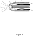
- FIG. 8 shows a lengthwise cross section of the tip of a catheter, schematically illustrating an alternate embodiment of both illumination using fiber optics and imaging using fiber optics.
- FIG. 9 shows a lengthwise cross section of a catheter with fluid channels, illustrating the principle of a complete assembly.
- FIG. 10 shows a series of perpendicular cross sections of an embodiment of a catheter with fluid channels, with reference to marked letters A-E in FIG. 9 .
- FIG. 11 shows a lengthwise cross section of the sleeve and how the internal assembly can be moved in to the sleeve.
- FIG. 12 shows a lengthwise cross section of the internal assembly.
- FIG. 13 shows an optional electric diagram for the catheter, for the case where several additional electric devices must be included in the internal assembly.
- FIG. 1 a is illustrated the principle of the employment of the sensing system with a fluid channel.
- a catheter sleeve 1 has a tapered tip 2 for less traumatic and safer entry in patient lumen or narrow passages.
- On the interior side of the tip 2 is reflective surface 3 that directs the light or treatment radiation from one or more sources 5 a , 5 b into the patient, while passing around the camera 4 placed inside the tip 2 .
- the sources 5 a and 5 b may be LEDs or lasers. By placing the sources behind the camera, space is gained for allowing larger components.
- the camera 4 may furthermore have a reflective exterior to improve illumination light guiding.
- the reflective surface 3 may have mirror finish or diffuse characteristics to achieve desired light patterns.
- the annular passage 8 between the camera 4 and the tip 2 may optionally also function as a fluid channel passing fluid or gas the same way as illumination light or other energy rays.
- This fluid can additionally serve as a means of keeping the camera lens area purged and clean. From an illumination standpoint, it is known that reflective surfaces act the same for interface to air or versus a liquid.
- the camera 4 may furthermore be slightly retracted behind the tip aperture for creating a clean fluid barrier for the vision.
- the light rays 6 emerging from the tip 2 illuminate the camera field of view 7 so the patient's interior can be observed.
- FIG. 1 b is schematically illustrated a perpendicular cross section of the tip 2 as designated by the line X-X located at a point of substantially maximum diameter of the catheter distal section in FIG. 1 a .
- the outside diameter of the camera D 1 is less than the inside diameter of the catheter D 2 , forming annular channel 8 that may serve as both illumination path and fluid channel.
- the annular channel external diameter will contract close to the distal tip of the catheter.
- the diameter ratio D 1 /D 2 may practically be in the range 0.2 to 0.8.
- the sensing catheter of the present invention will have a working outside maximum diameter of about 2 to 20 mm, preferably about 4 to 10 mm.
- the principles of the present invention can also be usefully employed in small diameter endoscopes requiring one or more fluid channels along with illumination or other provided radiant energy.
- FIG. 1 c is illustrated the configuration from FIG. 1 a , but here with an illumination energy source 5 a providing illumination rays 6 a , and a different diagnostics or treatment energy source 5 b providing diagnostics or treatment energy rays 6 b which here are shown by darker lines for clarity.
- the energy sources 5 a and 5 b may be activated simultaneously or alternately and may be one or more of each type.
- FIG. 1 d is illustrated the configuration from FIG. 1 a , but here with two diagnostics or treatment energy source 5 a , and 5 b providing diagnostics or treatment energy rays 6 b which here are shown by darker lines for clarity.
- the energy sources 5 a and 5 b may be activated simultaneously or alternately, providing similar or different energy types, and may be one or more of each type.
- FIG. 2 a is illustrated the arrangement from FIG. 1 , but here with the catheter tip 2 and reflective surface 3 , made of a translucent or semi translucent material.
- the catheter tip 2 and reflective surface 3 made of a translucent or semi translucent material.
- some light or other radiant energy rays 6 are reflected from the inside of the tip 2 similar to FIG. 1 , but some rays 6 are also allowed to pass through the tip 2 .
- This arrangement can be beneficial in creating different shape illumination patterns.
- FIG. 2 b is illustrated the arrangement from FIG. 2 a but here with an illumination energy source 5 a providing illumination rays 6 a , and a different diagnostics or treatment energy source 5 b providing diagnostics or treatment energy rays 6 b which here are shown by darker lines for clarity.
- the energy sources 5 a and 5 b may be activated simultaneously or alternately and may be one or more of each type.
- FIG. 2 c is illustrated the arrangement from FIG. 2 a but here with two diagnostics or treatment energy source 5 a , and 5 b providing diagnostics or treatment energy rays 6 b which here are shown by darker lines for clarity.
- the energy sources 5 a and 5 b may be activated simultaneously or alternately, providing similar or different energy types, and may be one or more of each type.
- FIG. 3 is shown a variation for one or more sources 5 a and 5 b , here mounted transversal to the camera 4 and illuminating via angled mirrors 10 a and 10 b .
- This allows sources with a wider foot print.
- the mirrors 10 a and 10 b can furthermore also serve to hold the sources 5 a and 5 b centered within the sleeve 1 or tip 2 .
- the camera 9 may be centered in the tip via supports 9 , which may be perpendicular to the mirrors 10 a and 10 b for minimum shading.
- FIG. 4 shows a perpendicular cross section at the camera 4 of the configuration in FIG. 3 .
- the camera is held in place or centered in the tip 2 of sleeve 1 by two or more supports 9 a , 9 b .
- the annular channel 8 provides illumination light guiding and optionally fluid flow.
- FIG. 5 shows a perpendicular cross section at the sources 5 a , 5 b of the configuration in FIG. 4 .
- the sources 5 a , 5 b may be held in place or centered in the tip 2 or sleeve 1 by the two mirrors 10 a , 10 b .
- the annular channel 8 provides flow on the side of the mirrors 10 a , 10 b.
- FIG. 6 a shows yet another variation on the sensing catheter from FIG. 1 , here using one or more fiber optics or other flexible energy guide assemblies 20 a , 20 b that send light or other radiant energy around the camera 4 because the radiant energy is guided by the reflective surface 3 inside the catheter tip, plus, to aid in energy conveyance, the exterior of camera 4 may also be reflective.
- the fiber optics assemblies receive light or treatment energy from remote sources arranged outside of the patient.
- FIG. 6 b shows yet another variation on the sensing catheter from FIG. 1 a , here using one illumination energy source 5 a behind the camera that directs rays 6 a to the patient, and a fiber optics or other energy guiding assembly 20 b that directs diagnostics or treatment radiant energy rays 6 b which here are shown by darker lines for clarity.
- the fiber optics assembly receives diagnostics or treatment energy from remote sources arranged outside of the patient.
- FIG. 7 shows a variation on the imaging from FIG. 1 a , here using a coherent fiber optics bundle 21 with an imaging lens 22 replacing the camera in FIG. 1 a .
- the camera is arranged to view the free end of the imaging fiber optics outside the patient.
- the fluid flow around the imaging fiber optics has the same characteristics as in FIG. 1 a to share the annular channel for illumination and/or other purposes, and also helps to keep the fiber optics lens clean.
- FIG. 8 shows a combination of FIG. 5 and FIG. 6 a to utilize remote imaging as well as remote sources.
- an imaging fiber assembly 21 as well as one or more illuminating or treatment fiber optics guides 20 a , 20 b.
- FIG. 9 shows one embodiment of the device that was schematically illustrated in FIG. 1 a , but now expanded with additional details.
- Fluid flow to the patient 40 enters the inner tubing 32 , passes through the distribution channel 31 in the mounting block 30 and emerges from the annular channel 8 in the tip 2 .
- Illumination or treatment sources 5 a , 5 b send light around the camera 4 though the same annular channel 8 via reflective surfaces 3 .
- Camera 4 may be centered in the tip by supports 9 .
- Fluid flow 41 from the patient enters the aperture 42 in the sleeve 1 and exits via the annular passage between inside of sleeve 1 and outside of inner tube 32 .
- the flow 40 may be reversed and used together with flow 41 to drain the patient faster.
- the camera 4 (or other sensor) and illumination (or other radiant energy providing) devices 5 a , 5 b are mounted to a sealed mounting block 30 that holds these devices in place and encapsulates electric connections to the insulated cable 33 that may be fed through the inner tubing 32 .
- FIG. 9 are also annotated several locations A-E for perpendicular cross sections that are shown in next figure.
- FIG. 10 shows a series of perpendicular cross sections from the embodiment of FIG. 9 .
- Section A shows the camera 4 centered in the annular channel 8 by supports 9 a , 9 b mounted to the camera.
- Section B shows sources 5 a , 5 b in the mounting block 30 and the apertures for liquid flow in the annular channel 8 .
- Section C shows the arrangement of flow channel 31 in the mounting block 30 to conduct liquid flow towards the tip.
- Section D shows the proximal end of the mounting block 30 , here creating a seal between the tip section of the catheter and the long section. This creates two separate fluid sections.
- the inner tube 32 is attached to the mounting block 30 and provides liquid flow to the tip and also houses and protects insulated electric cable 33 .
- Section E shows a cross section in line with the aperture 42 in the sleeve 1 .
- Flow 41 from the patient enters the aperture 42 and is led away from the patient in annular passage between sleeve 1 and inner tube 32 .
- FIGS. 11 and 12 show the embodiment of FIG. 9 by its main subassemblies, sleeve 1 including a tapered internally reflective tip, and the inner assembly 50 that consists of all other parts.
- the inner assembly 50 is inserted from the proximal end of the sleeve 1 and may also use a stop 40 in the sleeve 1 to position it at a desired point.
- the inner assembly 50 may also be positioned anywhere lengthwise inside the sleeve 1 without the stop 40 , and positioning may be guided by a vision system image inside the sleeve by internal markings, or all the way to partially extending from the tip as far as it can go.
- the invention provides flexibility to have different functionality internally using the same insertion sleeve. It also provides as options a completely disposable instrument with a low cost camera, or for re-use and sterilization of the inner assembly with costlier equipment.
- the inner assembly may thus range from a simple inner tubing to provide desired stiffness or liquid handling of a catheter, to full electro-optics instrumented versions for guiding insertion, diagnosis and treatment.
- the other advantage with the arrangement of FIGS. 11 and 12 is the ease of removal of the inner assembly from a patient in i.e., urology extended time catherization. This leaves only the sleeve 9 in place after the visual, diagnostic or treatment insertion procedure is complete.
- the sleeve 1 may be light weight and have a soft and thin wall design for greater patient comfort and increased inside cross section and can also include local stiffening by selected materials to prevent folding collapse. Additional features known from prior art like retaining balloons on catheters and manifolds at the distal end may be incorporated without deviating from the spirit of the invention.
- FIG. 13 shows how the invention can accommodate additional functions in the catheter without adding electric wires that interfere with the needed reliability and for minimum cross sectional area for the cable 33 .
- An interface may be provided in the catheter tip that creates a bus structure for connecting additional devices like diagnostic sensors, actuators, and energy control for treatment.
- the sensed radiant energy and the provided radiant energy are, preferably, both electromagnetic radiation, such as visible light, UV light, IR light, microwave energy, radio frequency energy, terahertz energy or X-ray energy.
- the radiant energy providing means can provide more than one type of radiant energy, for example, two types of radiant energy. One type of radiant energy can be provided for observation of the internal tissue, while a second type of radiant energy can be provided, for example, for treatment, diagnosis or healing. Where desirable, and practical, illumination need not be used, but one or more other radiant energy sources are provided to focus the same or a mixture of radiant energies onto an internal tissue site.
- the catheter internal assembly can be retracted and another internal assembly containing different radiant energy source(s) can be substituted therefor. Even so, preferably the radiant energy providing means and sensing means cooperate to allow a visual inspection of the body lumen.
- the sensing means used in the operation of the present invention is well known by itself, and comprises two main parts, the sensor and a conversion/transmitting device.
- the sensor can be a lens of a camera or a lens operatively connected to a fiber optic bundle.
- the radiation providing means is positioned at least behind and to the side of the sensor, for example, the lens, while preferably and where possible, the radiant energy providing means is positioned behind and to the side of the entire sensing means, for example as shown in FIG. 1 a of the Drawing.
- the radiant energy providing means is positioned behind and to the side of the sensor, which is the imaging lens 22 in FIG. 7 .
- the sensing means can be selected in conjunction with the radiant energy providing means to provide a visual image, a thermal image, surrounding temperature, a spectral analysis, a color analysis, a texture analysis, or a fluorescence analysis.
- the spirit of the invention has been primarily exemplified with a urinary catheter with vision, illumination and fluid handling, the invention can also be applied to catheters in other medical fields; medical or industrial endoscopes, and for other instruments that need to provide radiant energy and fluid handling capability in a confined cross sectional area.
- medical endoscopes that can usefully employ the inventive features of the present invention, there may be mentioned naso-gastric, gynecological, and pulmonary endoscopes.
Abstract
Description
Claims (50)
Priority Applications (1)
| Application Number | Priority Date | Filing Date | Title |
|---|---|---|---|
| US14/473,812 US10786205B2 (en) | 2011-06-06 | 2014-08-29 | Sensing catheter emitting radiant energy |
Applications Claiming Priority (4)
| Application Number | Priority Date | Filing Date | Title |
|---|---|---|---|
| US201161493521P | 2011-06-06 | 2011-06-06 | |
| PCT/US2012/040877 WO2012170401A2 (en) | 2011-06-06 | 2012-06-05 | Sensing catheter emitting radiant energy |
| US201414124435A | 2013-12-06 | 2013-12-06 | |
| US14/473,812 US10786205B2 (en) | 2011-06-06 | 2014-08-29 | Sensing catheter emitting radiant energy |
Related Parent Applications (3)
| Application Number | Title | Priority Date | Filing Date |
|---|---|---|---|
| US14124435 Continuation | |||
| PCT/US2012/040877 Continuation WO2012170401A2 (en) | 2011-06-06 | 2012-06-05 | Sensing catheter emitting radiant energy |
| US14124435 Continuation | 2012-06-05 |
Publications (2)
| Publication Number | Publication Date |
|---|---|
| US20160058383A1 US20160058383A1 (en) | 2016-03-03 |
| US10786205B2 true US10786205B2 (en) | 2020-09-29 |
Family
ID=47296696
Family Applications (2)
| Application Number | Title | Priority Date | Filing Date |
|---|---|---|---|
| US14/105,709 Expired - Fee Related US10238295B2 (en) | 2011-06-06 | 2013-12-13 | Sensing catheter emitting radiant energy |
| US14/473,812 Active 2035-03-18 US10786205B2 (en) | 2011-06-06 | 2014-08-29 | Sensing catheter emitting radiant energy |
Family Applications Before (1)
| Application Number | Title | Priority Date | Filing Date |
|---|---|---|---|
| US14/105,709 Expired - Fee Related US10238295B2 (en) | 2011-06-06 | 2013-12-13 | Sensing catheter emitting radiant energy |
Country Status (2)
| Country | Link |
|---|---|
| US (2) | US10238295B2 (en) |
| WO (1) | WO2012170401A2 (en) |
Cited By (1)
| Publication number | Priority date | Publication date | Assignee | Title |
|---|---|---|---|---|
| US20220233062A1 (en) * | 2021-01-26 | 2022-07-28 | Arthrex, Inc. | Endoscope thermal reflector |
Families Citing this family (35)
| Publication number | Priority date | Publication date | Assignee | Title |
|---|---|---|---|---|
| JP6430946B2 (en) | 2012-10-04 | 2018-11-28 | ザ ユニバーシティ オブ ウェスタン オーストラリア | Method and apparatus for characterizing biological tissue |
| JP6133571B2 (en) * | 2012-10-30 | 2017-05-24 | 株式会社ジンズ | Transmitted light observation device |
| EP2967414B1 (en) | 2013-03-11 | 2019-12-18 | University Of Utah Research Foundation | Sensor systems |
| US10219864B2 (en) | 2013-04-16 | 2019-03-05 | Calcula Technologies, Inc. | Basket and everting balloon with simplified design and control |
| US10188411B2 (en) | 2013-04-16 | 2019-01-29 | Calcula Technologies, Inc. | Everting balloon for medical devices |
| US8974472B2 (en) | 2013-04-16 | 2015-03-10 | Calcula Technologies, Inc. | Method for removing kidney stones |
| US20150305602A1 (en) * | 2014-04-23 | 2015-10-29 | Calcula Technologies, Inc. | Integrated medical imaging system |
| US10973393B2 (en) * | 2014-08-20 | 2021-04-13 | Clear Image Technology, Llc | Micro-endoscope and method of making same |
| WO2016077641A1 (en) * | 2014-11-12 | 2016-05-19 | Invuity, Inc. | Improved thermally controlled illumination devices |
| CN105662325B (en) * | 2014-11-24 | 2023-05-16 | 上海安清医疗器械有限公司 | Electronic laryngoscope |
| FR3031041B1 (en) * | 2014-12-26 | 2020-11-06 | Commissariat Energie Atomique | IMPLANTABLE OPTICAL BRAIN STIMULATION DEVICE INCLUDING A MULTI-CHANNEL CATHETER |
| GB2547104B (en) | 2015-12-15 | 2020-01-29 | Ev Offshore Ltd | Inspection assembly |
| WO2017158597A1 (en) * | 2016-03-14 | 2017-09-21 | Eyelum Ltd. | Miniature endoscopy system |
| US11351393B2 (en) * | 2016-04-14 | 2022-06-07 | Feldreich Caro Ruiz AB | Apparatus for use in irradiation therapy comprising ionization module and UV-light source |
| WO2017184728A1 (en) * | 2016-04-19 | 2017-10-26 | University Of Iowa Research Foundation | A rotating shield brachytherapy system |
| JP6773314B2 (en) * | 2016-08-03 | 2020-10-21 | 株式会社Okファイバーテクノロジー | Laser irradiation device |
| EP3537948A1 (en) * | 2016-11-09 | 2019-09-18 | Lina Medical International Operations AG | A device for use in hysteroscopy |
| US11304685B2 (en) * | 2017-07-05 | 2022-04-19 | Regents Of The University Of Minnesota | Lung biopsy devices, systems and methods for locating and biopsying an object |
| WO2019049159A1 (en) * | 2017-09-11 | 2019-03-14 | Eyelum Ltd. | Disposable miniature endoscopy system |
| DE112018006466T5 (en) * | 2017-12-19 | 2020-08-27 | Intuitive Surgical Operations, Inc. | Imaging systems and methods of use |
| US10912612B2 (en) | 2018-01-17 | 2021-02-09 | Gyrus Acmi, Inc. | System and device for treating body tissue |
| DE102018102587B3 (en) | 2018-02-06 | 2019-01-10 | Schölly Fiberoptic GmbH | Visualization module, endoscope and method for producing a visualization module |
| DE102018110082A1 (en) * | 2018-04-26 | 2019-10-31 | avateramedical GmBH | Sterile endoscope cover |
| US10433710B1 (en) * | 2018-05-22 | 2019-10-08 | Innovaquartz Inc. | In-vivo imaging and access system utilizing a canted working channel and a ring illuminated surgical camera |
| US10743755B1 (en) | 2018-10-11 | 2020-08-18 | InnovaQuartz LLC | Multi-spectrum ring illuminated surgical camera |
| DE102018126794A1 (en) | 2018-10-26 | 2020-04-30 | Hoya Corporation | Endoscope head with a housing element made of a transparent material |
| US11648081B2 (en) * | 2019-04-02 | 2023-05-16 | Intuitive Surgical Operations, Inc. | System and method for image detection during instrument grasping and stapling |
| CN110151101A (en) * | 2019-05-13 | 2019-08-23 | 上海英诺伟医疗器械有限公司 | Endoscope apparatus |
| CN110507912B (en) * | 2019-08-29 | 2021-05-11 | 鲍玉珍 | Terahertz wave physiotherapy terminal and terahertz wave physiotherapy system for early and medium gastric cancer |
| CN111700588B (en) * | 2020-06-05 | 2021-02-19 | 中国人民解放军军事科学院国防科技创新研究院 | Interventional imaging system |
| US10960094B1 (en) | 2020-06-16 | 2021-03-30 | Innovative Technologies | Disinfection system |
| GB2604346A (en) * | 2021-03-01 | 2022-09-07 | Medical Wireless Sensing Ltd | Dual-mode biosensor |
| GB202102891D0 (en) * | 2021-03-01 | 2021-04-14 | Medical Wireless Sensing Ltd | Dual-mode biosensor |
| WO2022251739A1 (en) * | 2021-05-28 | 2022-12-01 | Morejon Orlando V | Targeted suction catheter |
| DE102021132814A1 (en) | 2021-12-10 | 2023-06-15 | Olympus Winter & Ibe Gmbh | Medical lighting device, system for fluorescence image-guided surgery and method for producing a medical lighting device |
Citations (52)
| Publication number | Priority date | Publication date | Assignee | Title |
|---|---|---|---|---|
| US3902880A (en) | 1974-01-16 | 1975-09-02 | American Optical Corp | Method of making a fiber optic illuminating halo |
| US4418688A (en) * | 1981-07-06 | 1983-12-06 | Laserscope, Inc. | Microcatheter having directable laser and expandable walls |
| US5237984A (en) | 1991-06-24 | 1993-08-24 | Xomed-Treace Inc. | Sheath for endoscope |
| US5363838A (en) | 1992-12-09 | 1994-11-15 | George Gordon P | Fiberoptic intubating scope with camera and lightweight portable screen and method of using same |
| US5608834A (en) | 1994-10-07 | 1997-03-04 | United States Surgical Corporation | Liquid Light guide |
| US5833683A (en) * | 1996-01-12 | 1998-11-10 | Surgical Laser Technologies, Inc. | Laterally-emitting laser medical device |
| US6190380B1 (en) * | 1992-04-10 | 2001-02-20 | George S. Abela | Cell transfection apparatus and method |
| US20020087047A1 (en) | 1999-09-13 | 2002-07-04 | Visionscope, Inc. | Miniature endoscope system |
| US20030120271A1 (en) | 2000-06-30 | 2003-06-26 | Scimed Life Systems, Inc. | Medical probe with reduced number of temperature sensor wires |
| US20040006333A1 (en) | 1994-09-09 | 2004-01-08 | Cardiofocus, Inc. | Coaxial catheter instruments for ablation with radiant energy |
| JP2004029235A (en) | 2002-06-24 | 2004-01-29 | Osaka Gas Co Ltd | Endoscope |
| WO2004026125A1 (en) | 2002-09-19 | 2004-04-01 | Endospine Kinetics Limited | Endoscope |
| US20040097788A1 (en) * | 2002-05-30 | 2004-05-20 | Mourlas Nicholas J. | Apparatus and methods for coronary sinus access |
| US20040111012A1 (en) | 2002-09-30 | 2004-06-10 | Whitman Michael P. | Self-contained sterilizable surgical system |
| US20050113685A1 (en) | 2003-11-21 | 2005-05-26 | Michael Maschke | Medical system for examination or treatment |
| US20050187571A1 (en) | 2004-02-20 | 2005-08-25 | Siemens Aktiengesellschaft | Device for applying and monitoring medical atherectomy |
| US20050187422A1 (en) | 2004-02-20 | 2005-08-25 | Siemens Aktiengesellschaft | Device for implementing and monitoring endovascular brachytherapy |
| US20050277808A1 (en) | 2004-05-14 | 2005-12-15 | Elazar Sonnenschein | Methods and devices related to camera connectors |
| US20050283048A1 (en) | 2001-10-19 | 2005-12-22 | Visionscope, Llc | Portable imaging system employing a miniature endoscope |
| US20060025650A1 (en) | 2002-10-03 | 2006-02-02 | Oren Gavriely | Tube for inspecting internal organs of a body |
| US7030904B2 (en) | 1997-10-06 | 2006-04-18 | Micro-Medical Devices, Inc. | Reduced area imaging device incorporated within wireless endoscopic devices |
| US20070027520A1 (en) * | 2005-07-27 | 2007-02-01 | Sherburne Paul S | Stent removal from a body |
| US20070161853A1 (en) | 2004-02-18 | 2007-07-12 | Yasushi Yagi | Endoscope system |
| US20070182842A1 (en) | 2004-05-31 | 2007-08-09 | Medigus Ltd. | Reusable miniature camera head |
| US20080015565A1 (en) | 1998-11-20 | 2008-01-17 | Arthrocare Corporation | Electrosurgical apparatus and methods for ablating tissue |
| US20080082045A1 (en) * | 2006-09-15 | 2008-04-03 | Eric Goldfarb | Methods and devices for facilitating visualization in a surgical environment |
| US20080091064A1 (en) | 2006-10-17 | 2008-04-17 | Vadim Laser | Portable endoscope for intubation |
| US20080177138A1 (en) * | 2007-01-19 | 2008-07-24 | Brian Courtney | Scanning mechanisms for imaging probe |
| US7442167B2 (en) | 2002-03-22 | 2008-10-28 | Ethicon Endo-Surgery, Inc. | Integrated visualization system |
| US20090012367A1 (en) | 2003-12-17 | 2009-01-08 | Boston Scientific Scimed, Inc. | Medical device with oled illumination light source |
| US20090054803A1 (en) * | 2005-02-02 | 2009-02-26 | Vahid Saadat | Electrophysiology mapping and visualization system |
| US20090112198A1 (en) | 2007-10-24 | 2009-04-30 | Spectranetics | Liquid light guide catheter having biocompatible liquid light guide medium |
| US20090254074A1 (en) | 2008-04-02 | 2009-10-08 | Spectranetics | Liquid light-guide catheter with optically diverging tip |
| US20090299363A1 (en) | 2006-12-21 | 2009-12-03 | Vahid Saadat | Off-axis visualization systems |
| US20090318757A1 (en) | 2008-06-23 | 2009-12-24 | Percuvision, Llc | Flexible visually directed medical intubation instrument and method |
| US20090318798A1 (en) | 2008-06-23 | 2009-12-24 | Errol Singh | Flexible visually directed medical intubation instrument and method |
| US20100016842A1 (en) | 2008-07-21 | 2010-01-21 | Spectranetics | Tapered Liquid Light Guide |
| US20100030057A1 (en) | 2004-04-19 | 2010-02-04 | Oren Gavriely | Imaging catheter |
| US20100069713A1 (en) | 2008-09-18 | 2010-03-18 | Fujifilm Corporation | Electronic endoscope system |
| JP2010057960A (en) | 2009-12-14 | 2010-03-18 | Olympus Corp | Endoscope |
| US20100198012A1 (en) | 2007-04-05 | 2010-08-05 | Scopeguard Limited | Apparatus for deploying endoscope |
| US20100204546A1 (en) | 2007-05-10 | 2010-08-12 | Noam Hassidov | Semi disposable endoscope |
| US20100217080A1 (en) | 2009-02-24 | 2010-08-26 | Visionscope Technologies, Llc | Disposable Sheath for Use with an Imaging System |
| US20100238279A1 (en) | 2007-03-16 | 2010-09-23 | Durr Dental Ag | Diagnostic Camera and Attachment for the Implementation Thereof |
| US20100245549A1 (en) | 2007-11-02 | 2010-09-30 | The Trustees Of Columbia University In The City Of New York | Insertable surgical imaging device |
| US20100286475A1 (en) | 2009-05-08 | 2010-11-11 | Boston Scientific Scimed, Inc. | Endoscope with distal tip having encased optical components and display orientation capabilities |
| WO2010146587A1 (en) | 2009-06-18 | 2010-12-23 | Peer Medical Ltd. | Multi-camera endoscope |
| US20110028790A1 (en) | 2004-09-24 | 2011-02-03 | Vivid Medical, Inc. | Disposable endoscopic access device and portable display |
| US7922654B2 (en) | 2004-08-09 | 2011-04-12 | Boston Scientific Scimed, Inc. | Fiber optic imaging catheter |
| US7922650B2 (en) | 2004-03-23 | 2011-04-12 | Boston Scientific Scimed, Inc. | Medical visualization system with endoscope and mounted catheter |
| US20110118547A1 (en) | 2009-11-19 | 2011-05-19 | Fujifilm Corporation | Endoscope apparatus |
| US20110288372A1 (en) | 2008-12-10 | 2011-11-24 | Lasse Kjeld Gjoeske Petersen | Endoscope having a camera housing and method for making a camera housing |
Family Cites Families (1)
| Publication number | Priority date | Publication date | Assignee | Title |
|---|---|---|---|---|
| US20090031879A1 (en) * | 2007-07-31 | 2009-02-05 | Phillip Jason Everly | Guitar/bass case with built-in tuner |
-
2012
- 2012-06-05 WO PCT/US2012/040877 patent/WO2012170401A2/en active Application Filing
-
2013
- 2013-12-13 US US14/105,709 patent/US10238295B2/en not_active Expired - Fee Related
-
2014
- 2014-08-29 US US14/473,812 patent/US10786205B2/en active Active
Patent Citations (54)
| Publication number | Priority date | Publication date | Assignee | Title |
|---|---|---|---|---|
| US3902880A (en) | 1974-01-16 | 1975-09-02 | American Optical Corp | Method of making a fiber optic illuminating halo |
| US4418688A (en) * | 1981-07-06 | 1983-12-06 | Laserscope, Inc. | Microcatheter having directable laser and expandable walls |
| US5237984A (en) | 1991-06-24 | 1993-08-24 | Xomed-Treace Inc. | Sheath for endoscope |
| US6190380B1 (en) * | 1992-04-10 | 2001-02-20 | George S. Abela | Cell transfection apparatus and method |
| US5363838A (en) | 1992-12-09 | 1994-11-15 | George Gordon P | Fiberoptic intubating scope with camera and lightweight portable screen and method of using same |
| US5363838B1 (en) | 1992-12-09 | 2000-03-28 | Gordon P George | Fiberoptic intubating scope with camera and lightweight portable screen and method of using same |
| US20040006333A1 (en) | 1994-09-09 | 2004-01-08 | Cardiofocus, Inc. | Coaxial catheter instruments for ablation with radiant energy |
| US5608834A (en) | 1994-10-07 | 1997-03-04 | United States Surgical Corporation | Liquid Light guide |
| US5833683A (en) * | 1996-01-12 | 1998-11-10 | Surgical Laser Technologies, Inc. | Laterally-emitting laser medical device |
| US7030904B2 (en) | 1997-10-06 | 2006-04-18 | Micro-Medical Devices, Inc. | Reduced area imaging device incorporated within wireless endoscopic devices |
| US20080015565A1 (en) | 1998-11-20 | 2008-01-17 | Arthrocare Corporation | Electrosurgical apparatus and methods for ablating tissue |
| US20020087047A1 (en) | 1999-09-13 | 2002-07-04 | Visionscope, Inc. | Miniature endoscope system |
| US20030120271A1 (en) | 2000-06-30 | 2003-06-26 | Scimed Life Systems, Inc. | Medical probe with reduced number of temperature sensor wires |
| US20050283048A1 (en) | 2001-10-19 | 2005-12-22 | Visionscope, Llc | Portable imaging system employing a miniature endoscope |
| US7442167B2 (en) | 2002-03-22 | 2008-10-28 | Ethicon Endo-Surgery, Inc. | Integrated visualization system |
| US20040097788A1 (en) * | 2002-05-30 | 2004-05-20 | Mourlas Nicholas J. | Apparatus and methods for coronary sinus access |
| JP2004029235A (en) | 2002-06-24 | 2004-01-29 | Osaka Gas Co Ltd | Endoscope |
| WO2004026125A1 (en) | 2002-09-19 | 2004-04-01 | Endospine Kinetics Limited | Endoscope |
| US20040111012A1 (en) | 2002-09-30 | 2004-06-10 | Whitman Michael P. | Self-contained sterilizable surgical system |
| US20060025650A1 (en) | 2002-10-03 | 2006-02-02 | Oren Gavriely | Tube for inspecting internal organs of a body |
| US20050113685A1 (en) | 2003-11-21 | 2005-05-26 | Michael Maschke | Medical system for examination or treatment |
| US20090012367A1 (en) | 2003-12-17 | 2009-01-08 | Boston Scientific Scimed, Inc. | Medical device with oled illumination light source |
| US20070161853A1 (en) | 2004-02-18 | 2007-07-12 | Yasushi Yagi | Endoscope system |
| US20050187422A1 (en) | 2004-02-20 | 2005-08-25 | Siemens Aktiengesellschaft | Device for implementing and monitoring endovascular brachytherapy |
| US20050187571A1 (en) | 2004-02-20 | 2005-08-25 | Siemens Aktiengesellschaft | Device for applying and monitoring medical atherectomy |
| US7922650B2 (en) | 2004-03-23 | 2011-04-12 | Boston Scientific Scimed, Inc. | Medical visualization system with endoscope and mounted catheter |
| US20100030057A1 (en) | 2004-04-19 | 2010-02-04 | Oren Gavriely | Imaging catheter |
| US20050277808A1 (en) | 2004-05-14 | 2005-12-15 | Elazar Sonnenschein | Methods and devices related to camera connectors |
| US20050288546A1 (en) | 2004-05-14 | 2005-12-29 | Elazar Sonnenschein | Device employing camera connector |
| US20070182842A1 (en) | 2004-05-31 | 2007-08-09 | Medigus Ltd. | Reusable miniature camera head |
| US7922654B2 (en) | 2004-08-09 | 2011-04-12 | Boston Scientific Scimed, Inc. | Fiber optic imaging catheter |
| US20110028790A1 (en) | 2004-09-24 | 2011-02-03 | Vivid Medical, Inc. | Disposable endoscopic access device and portable display |
| US20090054803A1 (en) * | 2005-02-02 | 2009-02-26 | Vahid Saadat | Electrophysiology mapping and visualization system |
| US20070027520A1 (en) * | 2005-07-27 | 2007-02-01 | Sherburne Paul S | Stent removal from a body |
| US20080082045A1 (en) * | 2006-09-15 | 2008-04-03 | Eric Goldfarb | Methods and devices for facilitating visualization in a surgical environment |
| US20080091064A1 (en) | 2006-10-17 | 2008-04-17 | Vadim Laser | Portable endoscope for intubation |
| US20090299363A1 (en) | 2006-12-21 | 2009-12-03 | Vahid Saadat | Off-axis visualization systems |
| US20080177138A1 (en) * | 2007-01-19 | 2008-07-24 | Brian Courtney | Scanning mechanisms for imaging probe |
| US20100238279A1 (en) | 2007-03-16 | 2010-09-23 | Durr Dental Ag | Diagnostic Camera and Attachment for the Implementation Thereof |
| US20100198012A1 (en) | 2007-04-05 | 2010-08-05 | Scopeguard Limited | Apparatus for deploying endoscope |
| US20100204546A1 (en) | 2007-05-10 | 2010-08-12 | Noam Hassidov | Semi disposable endoscope |
| US20090112198A1 (en) | 2007-10-24 | 2009-04-30 | Spectranetics | Liquid light guide catheter having biocompatible liquid light guide medium |
| US20100245549A1 (en) | 2007-11-02 | 2010-09-30 | The Trustees Of Columbia University In The City Of New York | Insertable surgical imaging device |
| US20090254074A1 (en) | 2008-04-02 | 2009-10-08 | Spectranetics | Liquid light-guide catheter with optically diverging tip |
| US20090318757A1 (en) | 2008-06-23 | 2009-12-24 | Percuvision, Llc | Flexible visually directed medical intubation instrument and method |
| US20090318798A1 (en) | 2008-06-23 | 2009-12-24 | Errol Singh | Flexible visually directed medical intubation instrument and method |
| US20100016842A1 (en) | 2008-07-21 | 2010-01-21 | Spectranetics | Tapered Liquid Light Guide |
| US20100069713A1 (en) | 2008-09-18 | 2010-03-18 | Fujifilm Corporation | Electronic endoscope system |
| US20110288372A1 (en) | 2008-12-10 | 2011-11-24 | Lasse Kjeld Gjoeske Petersen | Endoscope having a camera housing and method for making a camera housing |
| US20100217080A1 (en) | 2009-02-24 | 2010-08-26 | Visionscope Technologies, Llc | Disposable Sheath for Use with an Imaging System |
| US20100286475A1 (en) | 2009-05-08 | 2010-11-11 | Boston Scientific Scimed, Inc. | Endoscope with distal tip having encased optical components and display orientation capabilities |
| WO2010146587A1 (en) | 2009-06-18 | 2010-12-23 | Peer Medical Ltd. | Multi-camera endoscope |
| US20110118547A1 (en) | 2009-11-19 | 2011-05-19 | Fujifilm Corporation | Endoscope apparatus |
| JP2010057960A (en) | 2009-12-14 | 2010-03-18 | Olympus Corp | Endoscope |
Cited By (1)
| Publication number | Priority date | Publication date | Assignee | Title |
|---|---|---|---|---|
| US20220233062A1 (en) * | 2021-01-26 | 2022-07-28 | Arthrex, Inc. | Endoscope thermal reflector |
Also Published As
| Publication number | Publication date |
|---|---|
| WO2012170401A3 (en) | 2014-05-08 |
| WO2012170401A2 (en) | 2012-12-13 |
| US10238295B2 (en) | 2019-03-26 |
| US20160058383A1 (en) | 2016-03-03 |
| US20140107496A1 (en) | 2014-04-17 |
Similar Documents
| Publication | Publication Date | Title |
|---|---|---|
| US10786205B2 (en) | Sensing catheter emitting radiant energy | |
| JP7399511B2 (en) | Electrosurgical energy delivery structure and electrosurgical device incorporating the same | |
| EP1804640B1 (en) | Solid state illumination for endoscopy | |
| US8187180B2 (en) | Video rectractor | |
| US9622682B2 (en) | Medical device with OLED illumination light source | |
| US9261662B2 (en) | Photoelectric conversion connector, optical transmission module, imaging apparatus, and endoscope | |
| JP4794916B2 (en) | Endoscope and endoscope system | |
| US20150031947A1 (en) | Endoscope | |
| EP3829474B1 (en) | Electrosurgical instrument | |
| US9339174B2 (en) | Device and method for viewing a body lumen | |
| CA3108250C (en) | Fiberscope having excellent insertability | |
| EP2923631B1 (en) | Endoscope insertion portion and endoscope | |
| WO2016157416A1 (en) | Endoscope, attachment for endoscope, and endoscope system | |
| KR20150010467A (en) | Catheter | |
| RU2776771C1 (en) | Electrosurgical instrument for delivering radio frequency (rf) and/or microwave energy to biological tissue | |
| US11503989B2 (en) | Multi-channel system | |
| WO2020070862A1 (en) | Leading end part of endoscope | |
| JP4668483B2 (en) | Endoscope device | |
| JP2011206567A (en) | Endoscope system | |
| WO2023055600A1 (en) | Systems and methods for configurable endoscope bending section | |
| CN115067851A (en) | Tip for a medical insertion vision device | |
| CA3210610A1 (en) | Fiberscope having excellent insertability | |
| CN116099102A (en) | Medical catheter probe, medical catheter, medical device and system | |
| JP2005312829A (en) | Illumination device for endoscope and endoscope using same |
Legal Events
| Date | Code | Title | Description |
|---|---|---|---|
| AS | Assignment |
Owner name: PERCUVISION LLC, OHIO Free format text: CORRECTIVE ASSIGNMENT TO CORRECT THE APPLICATION NUMBER 14479812 REEL 041218, FRAME 0426 PREVIOUSLY RECORDED ON REEL 041218 FRAME 0426. ASSIGNOR(S) HEREBY CONFIRMS THE ASSIGNMENT;ASSIGNORS:SINGH, ERROL O;HELLSTROM, AKE A;SIGNING DATES FROM 20160929 TO 20161012;REEL/FRAME:042799/0399 |
|
| STPP | Information on status: patent application and granting procedure in general |
Free format text: ADVISORY ACTION MAILED |
|
| STPP | Information on status: patent application and granting procedure in general |
Free format text: NON FINAL ACTION MAILED |
|
| STPP | Information on status: patent application and granting procedure in general |
Free format text: RESPONSE TO NON-FINAL OFFICE ACTION ENTERED AND FORWARDED TO EXAMINER Free format text: NON FINAL ACTION MAILED |
|
| STPP | Information on status: patent application and granting procedure in general |
Free format text: RESPONSE TO NON-FINAL OFFICE ACTION ENTERED AND FORWARDED TO EXAMINER |
|
| STPP | Information on status: patent application and granting procedure in general |
Free format text: NOTICE OF ALLOWANCE MAILED -- APPLICATION RECEIVED IN OFFICE OF PUBLICATIONS |
|
| STPP | Information on status: patent application and granting procedure in general |
Free format text: AWAITING TC RESP., ISSUE FEE NOT PAID |
|
| STPP | Information on status: patent application and granting procedure in general |
Free format text: PUBLICATIONS -- ISSUE FEE PAYMENT VERIFIED |
|
| STCF | Information on status: patent grant |
Free format text: PATENTED CASE |