WO2025013313A1 - ペットに体毛を介して取り付けるペット用ヘアリング - Google Patents
ペットに体毛を介して取り付けるペット用ヘアリング Download PDFInfo
- Publication number
- WO2025013313A1 WO2025013313A1 PCT/JP2024/001550 JP2024001550W WO2025013313A1 WO 2025013313 A1 WO2025013313 A1 WO 2025013313A1 JP 2024001550 W JP2024001550 W JP 2024001550W WO 2025013313 A1 WO2025013313 A1 WO 2025013313A1
- Authority
- WO
- WIPO (PCT)
- Prior art keywords
- joint
- pair
- magnetic
- hair
- pet
- Prior art date
- Legal status (The legal status is an assumption and is not a legal conclusion. Google has not performed a legal analysis and makes no representation as to the accuracy of the status listed.)
- Ceased
Links
Images

Classifications
-
- A—HUMAN NECESSITIES
- A01—AGRICULTURE; FORESTRY; ANIMAL HUSBANDRY; HUNTING; TRAPPING; FISHING
- A01K—ANIMAL HUSBANDRY; AVICULTURE; APICULTURE; PISCICULTURE; FISHING; REARING OR BREEDING ANIMALS, NOT OTHERWISE PROVIDED FOR; NEW BREEDS OF ANIMALS
- A01K29/00—Other apparatus for animal husbandry
Definitions
- the present invention relates to a pet accessory that is attached to a pet via its hair, in particular a hair ring that is removably attached to the pet's hair by a pair of connecting members that are joined at their tips, using a clamping force created by magnetic and/or physical bonding.
- pet accessories are popular. However, most of the accessories are attached by tying ribbons or by attaching them to collars, and there is no custom of attaching them to pet hair. The reason is that if the accessories are attached to the ear hair, the animal will try to remove it due to its habit. Therefore, it is desirable to provide accessories that cannot be easily removed by the pet's habitual movements, but there is a problem that it is difficult to adjust the attachment strength when attaching to the pet's hair with a clip or the like. That is, if the attachment is too strong, there is a risk that the hair will come off and injure the pet, while if it is too weak, it will easily come off due to the pet's movements and be lost.
- Patent Document 1 a proposal has been proposed to attach the accessories by holding the pet's hair with a pair of magnets (Patent Document 1), but attaching the accessories to the pet's hair is difficult for the following reasons.
- Dogs' movements are different from humans' in that they are very active, and when clamping their fur, the clamp is not large enough to easily come off (Patent Document 1). Therefore, if the pair of connectors is made disk-shaped to increase the contact surface and the adhesive force (Patent Document 2), the clamp looks bad and is difficult to remove.
- Patent Document 3 Even if a rare earth magnet with strong magnetic force is used, simply bonding the tips of a pair of magnetic coupling bodies directly to each other does not provide sufficient adhesive force to grip the pet's hair.
- a pet hair ring which is a pet accessory that is attached to a pet by clamping its hair
- a pair of front and back joints that clamp the pet's hair are desirable in which the tips are butted up and joined together.
- the joint consisting of the pair of joints needs to have the following functions necessary for attachment to a pet, in order to realize quick attachment by clamping the body hair instantly in the case of a moving pet when gripping the body hair, 1) a first function of aligning the centers of the tips of the pair of joints, and maintaining the joined state of the pair of joints that are butted together, 2) a second function of locking the joined state of the pair of joints, and further, a third function of preventing the hair from falling out of the pinched hair, and 3) a third function of preventing the hair from falling out of the pet's hair gripped by the pair of joints.
- the first function is suited to the attraction between magnets, but it is difficult to provide sufficient strength when clamping the magnets by making the magnetic joint surface small enough to look good as an accessory, and the second locking function is insufficient.
- sufficient clamping force is provided, it is difficult to make the magnets easy to attach and detach. Therefore, it is desirable to provide a pet accessory that has a clamping force appropriate for gripping pet hair, while also being easy to attach and detach.
- the inventors have conducted extensive research and found that when adopting a magnetic joining method for a pair of joined bodies, the joining surfaces of the pair of magnetic joints are narrowed to 0.5 mm to 1 mm in diameter, and the pair of magnetic joints exhibit magnetic characteristics of an adhesive force F (surface magnetic flux density B x adhesive area S) of 0.2 to 1.0 kgf, so that the hair is firmly clamped between them.
- F surface magnetic flux density B x adhesive area S
- At least one of the pair of rod-shaped magnetic joints must be made of a rare earth magnet, preferably a neo-magnet, and 2) the pair of magnetic joints must be formed into a rod shape and surrounded by a yoke body to join the tips together to provide a second locking function, and then 3) at least one of the pair of joined surfaces must be formed with a slip prevention surface for the hair, providing a third slip prevention function, and the pair of magnetic joints must be formed into a rod shape and at least one of the magnetic joints must be pinched and bent in the bending direction relative to the axis connecting the pair of magnetic joints to separate them, so that even a strong magnetic joint can be relatively easily separated.
- a rare earth magnet preferably a neo-magnet
- a structure in which a pair of joining bodies are fitted together by axial movement is desirable to provide the first centering function, but when considering the function of clamping the body hair with the pair of joining bodies to have the second locking function after moving in the axial direction, a structure in which the pair of joining bodies are moved relatively around the axis to lock the axial movement is desirable, rather than a screw structure, and this alone raises the issue of how to configure an anti-slip function for the clamped body hair.
- the inventors have discovered that when having a centering function by axial movement and a locking function by relative movement around the axis, applying a biasing force in the axial direction opposite to that when the pair of joining bodies is joined reinforces the locking function and provides an anti-slip function for the body hair clamped at the joint.
- the present invention considers that when a pair of joined bodies are magnetically joined, it is necessary to set a jewelry part that can be seen from the outside on the front body of the pair of magnetic joined bodies, and when stacking the jewelry part and the magnetic joined body to form the front body, the jig containing the magnetic joined body and the satiating part is made into a cylindrical body with a yoke function, and the yoke body is sandwiched between the magnetic joined body of the other back body, magnetic circuits MC1 and MC2 with the flow of magnetic lines of force shown in Figures 2(a) and (b) are formed, and it has been discovered that a pet's body hair can be firmly held with a rare earth magnet including a small neodymium magnet, while if the back body is made into a rod shape of 5 mm or more that can be pinched with fingers, the pair of joined bodies can be separated by bending it, thus completing the first invention.
- the pair of cylindrical bodies are maintained in a locked state by an axial biasing force, which not only prevents the pair of cylindrical bodies from coming off, but also maintains the function of clamping the body hair by fitting the pair of cylindrical bodies together (see Fig. 10(e)), thereby achieving the third function, and thus the second invention was completed.
- the first invention is a pet hair ring, which is a pet accessory that is attached to a pet by clamping its body hair, and which comprises a joint 10 consisting of a pair of front and back joints, a front joint 11 and a back joint 12, which are joined by butting their tips together and which hold the pet's body hair, and a decorative part such as jewelry attached to the front joint 11 which is visible from the outside when attached, and the joint consisting of the pair of joints has the following functions necessary for attachment to a pet: a first centering function of aligning the center of the pair of joints by clamping the body hair when gripping the hair, a second locking function of locking the joined state of the pair of joints, and a third anti-falling function of preventing the pair of joints from falling out of the pet's hair.
- the front joint 11 of the joint is configured by stacking a jewelry body 11a such as a gemstone and a magnetic joint body 11b, and housing them inside a cylindrical body 10c.
- the back side joint body 12 on the opposite side of the front side joint body is formed into a rod-like shape having a length that can be held by fingertips, and the back side joint body 12 is formed by enclosing the magnetic joint body 12a in a cylindrical body 12b.
- At least one of the magnetic joints 11b, 12a has a thickness of 3 mm and a magnetic flux density B of at least 3000 Gauss or more, and is made of a rare earth magnet including a neodymium magnet that has a magnetic characteristic of an adhesive force F (surface magnetic flux density B x adhesive area S) of 0.2 to 1.0 kgf when the body hair is held with the joint surface having a joint area S of 5 mm ⁇ to 10 mm ⁇ , and has a pair of magnetic lines of force at the joints, and has the first centering function;
- the front magnetic joint 11b and the back magnetic joint 12a form a magnetic circuit MC1 or MC2 in which magnetic lines of force flow by sandwiching the cylindrical yoke body 11c or by passing through both the cylindrical yoke body 11c and the cylindrical yoke body 12b, and a second locking function is provided for locking the pair of joints so that they do not come apart by the strength of the magnetic lines of force at the pair of joints;
- a pet hair ring which is a pet accessory that is attached to a pet by clamping its body hair, and which comprises a joint 110 consisting of a pair of front and back joints, front joint 111 and back joint 112, which are joined by butting their tips together and which clamp the pet's body hair, and a decorative part such as jewelry attached to front joint 11 which is visible from the outside when attached, and the joint consisting of the pair of joints has the following functions necessary for attachment to a pet: a first centering function of aligning the center of the pair of joints by clamping the body hair when gripping the hair, a second locking function of locking the joined state of the pair of joints, and a third anti-falling function of preventing the pet's hair from falling out at the pair of joints.
- the front joint 111 of the joint is configured to contain at least a jewelry body 111a such as a gemstone within a cylindrical body 111c
- the back-side joint body 112 on the opposite side of the front-side joint body is configured to include an elastic body G that biases the axial direction of the cylindrical body 111c in one of the cylindrical bodies, preferably the cylindrical body 112b, and is formed into a rod shape that can be held by fingertips, for example, with a length of 5 mm or more.
- the pair of front and back joint bodies 111, 112 are provided with engagement parts 111d, 112e on the cylindrical bodies 111c, 112b, which engage with each other by the axial movement of the cylindrical bodies 111c, 112b, forming first engagement parts, and are joined via the first engagement parts, and have the first centering function
- D) the pair of cylindrical bodies 111c, 112b of the joint have second engagement portions 111e, 112f that prevent axial movement by relative movement around the axis, and have a second locking function that prevents the pair of cylindrical bodies 111c, 112b from separating in the axial direction
- the pair of cylindrical bodies 111c, 112b increase and decrease the joining depth in the axial direction of the engaging portions 111e, 112f that engage with each other by relative movement around the axis, and are biased in the axial direction by the elastic body 112a, and have a third anti-falling function that prevents the pair of cylindrical bodies 111c, 112b from falling out of the pet
- a pet hair ring which is an accessory that is attached to a pet by clamping its body hair, and which comprises a joint 110 consisting of a pair of front and back joints, front and back joints 111 and 112, which are joined together with their tips butted against each other and which clamp the pet's body hair, and a decorative part such as jewelry attached to front joint 111 which is visible from the outside when attached.
- Joint 110 consisting of a pair of joints has the following functions necessary for attachment to a pet: 1) a first centering function for aligning the center of the pair of joints by clamping the hair when gripping it, 2) a second locking function for locking the joined state of the pair of joints, and 3) a third fall-off prevention function for preventing the pair of joints from falling off the pet's hair.
- A) The front joint 111 of the joint is configured by stacking a jewelry body 111a such as a gemstone and a magnetic joint body 111b, and housing them inside a cylindrical body 110c.
- the rear joint 12 on the opposite side of the front joint is formed into a rod-like shape having a length that can be held by the fingertips, and includes a magnetic joint 12a enclosed in a cylindrical body 12b.
- the pair of front and back joint bodies 111, 112 are provided with first engaging portions 111d, 112e that are fitted to each other by the axial movement of the cylindrical body 111c and the cylindrical body 112b, and are configured to be joined via the first engaging portions.
- the magnetic joint of the pair of magnetic joint bodies 111, 112 and the first engaging portions perform the first centering function
- D) the cylindrical bodies 111c, 112b of the pair of joined bodies have second engagement portions 111e, 112f that prevent axial movement by relative movement around the axis, thereby performing a second locking function that prevents the pair of cylindrical bodies 111c, 112b from separating in the axial direction
- E) the pair of cylindrical bodies 111c, 112b are urged in the axial direction by the magnetic joining force of the pair of magnetic joined bodies 111, 112 together with the relative movement around the axis, thereby providing a third anti-falling function that prevents the pair of joined bodies from falling off the pet's hair at the pair of joined parts.
- F) The pair of connecting bodies 11 and 12 can be unlocked and separated by rotating them relatively about an axis L passing through the center of both bodies, thereby enabling the pair of connecting bodies 111 and 112 to be removed.
- a good-looking pet accessory can be provided by comprising joints 10, 110 consisting of a pair of front and back joints 11, 111 and 12, 112, which are joined together with their tips butted against each other and which hold the pet's hair, and a decorative part such as jewelry attached to the front joints 11, 111 which can be seen from the outside when attached (see Figures 1 (a) and (b)).
- the joints consisting of the pair of joints have the functions necessary for attachment to a pet, namely, a first centering function of aligning the center of the pair of joints by pinching the hair when gripping it, a second locking function of locking the joined state of the pair of joints, and a third fall-off prevention function of preventing the hair from falling out of the pet's hair at the pair of joints, so that it can be attached with a single touch to the hair of a pet which moves around a lot, while the locking function and hair fall-off function prevent the hair from falling out of the pet's hair.
- the magnetic bonding method of the first invention has a magnetic flux density B of at least 3000 gauss at a thickness of 3 mm, and the bonding surface has a bonding area S of 5 mm ⁇ to 10 mm ⁇ , and exhibits magnetic properties of an adhesive force F (surface magnetic flux density B x adhesive area S) of 0.2 to 1.0 kgf, preferably 0.3 to 0.8 kgf, when the hair is clamped, and can provide an accessory that can be called a hair ring that is optimal for clamping and attaching the hair of a pet.
- an adhesive force F surface magnetic flux density B x adhesive area S
- the magnetic flux density of the magnet affects the adhesive force through the hair, and that if the adhesive force is exerted with a magnetic flux density of 3000 gauss, preferably 4000 gauss, taking into account the density of the hair to be pinched, a hair gripping force that does not injure the animal even in the animal's habitual movements can be obtained.
- a magnetic flux density of 3000 gauss preferably 4000 gauss
- the hair gripping force ⁇ F is determined by the synergistic effect of the friction coefficient ⁇ of the magnetic joint surface and the adhesive force F of the magnetic joint surface, and by adjusting the hair gripping force ⁇ F, the accessory can be attached through the hair with an appropriate desired strength that does not injure the animal, and a pet accessory that will not come off even in the animal's habitual movements can be provided.
- the magnetic attraction force of the pair of magnetic joining bodies 11 and 12 can be reinforced.
- the back body 12 of the pair of magnetic joining bodies is surrounded by silicone rubber 12e and a detachable annular portion 11e is provided at or near the rear end, the joining can be easily detached by bending the pair of magnetic joining bodies 11 and 12 against the axis.
- the joint surface of one or both of the pair of magnetic joints of the present invention is preferably formed with a slip prevention surface with a friction coefficient ⁇ so as to reinforce the adhesive force.
- the joint surface is preferably provided with a rubber viscoelastic layer made of silicone resin or synthetic resin, and these are preferably abutted against each other, or a metal concave-convex complementary joint surface, a parallel concave groove and a convex strip that mesh with each other, or a convex-convex complementary part that meshes with each other with a concentric concave groove and a convex strip that mesh with each other.
- the concaves and convexities may be interlocked at a wavy part or a zigzag shape with multiple concaves and convexities to ensure a constant friction coefficient, or a thin plate of silicone rubber or the like may be arranged.
- one concave part and one convex part may be loosely fitted and interlocked, or multiple circular protrusions may be arranged to interlock with each other to form a slip prevention part.
- the magnet must have a small joining surface, for example a 5-10 mm ⁇ magnet joining surface, and must have a magnetic flux density of 3000 Gauss, preferably 4000 Gauss or more. It is recommended to use a rare earth magnet. In particular, a neodymium magnet is used, and it is recommended to form a magnetic circuit MC1 or 2 that can ensure an appropriate flow of magnetic lines in both magnetic joining bodies by using the yoke body 11c of the front body 11 or the cylindrical yoke bodies 11c and 11b of the front body 11 and the back body 12. When forming the magnetic circuit MC2, sufficient magnetic attraction can be achieved even if a samarcova magnet is used instead of neodymium stone.
- cylindrical neodymium magnets such as N52, N45, N40, N40SH, N40UH, N35H, and N35SH can be used.
- the magnet is preferably in the form of a columnar rod with a diameter of 5 mm to 10 mm, and a jewel or other decorative part can be attached to the other end of the joint surface.
- the first centering function, the second locking function, and the third anti-slip function can be achieved by physical joining, similar to the magnetic joining method.
- the first centering function of the pair of cylindrical bodies constituting the pair of joined bodies is achieved by fitting together in the axial direction, so that detachment in the axial direction can be easily locked by relative movement around the axis, and the locking function is not released by the animal's movement due to the axial biasing force of the elastic body.
- the first centering function, the second locking function, and the third anti-slip function can be achieved by combining physical and magnetic connections.
- the first centering function, the second locking function, and the third anti-slip function can be reinforced, so the magnetic connection structure according to the first invention can be simplified.
- the physical connections can be reinforced by magnetic connections, not only can the magnetic connection structure be simplified, but there is also no need to attach an elastic body, which is essential for physical connections.
- Photographs (a) and (b) show the attached state of a pet accessory, a hair ring, according to the present invention.
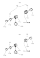
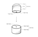
- 1A is a perspective view showing an exploded and assembled state of a first embodiment of a pet hair ring of the present invention
- FIG. 1B is a perspective view showing an exploded and assembled state of a second embodiment of a pet hair ring of the present invention.
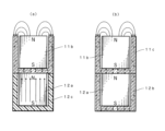
- 1 is a conceptual diagram showing the flow of magnetic field lines in a magnetic circuit MC1 (a) constituting a first embodiment of a pet hair ring of the present invention and a magnetic circuit MC2 (b) constituting a second embodiment of the present invention.
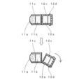
- FIG. FIG. 2 is a functional explanatory diagram of the pet hair ring of the present invention.
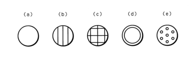
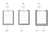
- 1A to 1E are plan views showing various aspects of the slip-drop prevention surface of the joining end surface.
- 1A and 1B are cross-sectional views showing various configuration examples of the back side body of a pair of magnetic joints.
- (a) shows a case where the magnetic joint 12a is surrounded by a cylindrical yoke body 12b
- (b) shows a case where the magnetic joint 12b is surrounded by a rubber cover 12c
- (c) shows a case where the magnetic joint 12a is surrounded by a cylindrical yoke body 12b and its outer periphery is surrounded by a rubber cover 12c.
- the magnetic joints are covered with the rubber cover 12c to facilitate separation of the pair of magnetic joints.
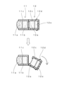
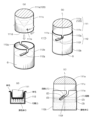
- FIG. 1 is a cross-sectional view for explaining the function of a first embodiment of the present invention
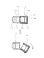
- FIG. 11 is a cross-sectional view for explaining the function of a second embodiment of the present invention
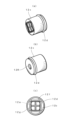
- 1A is a perspective view of the rear body 12 of a pair of magnetic coupling bodies as viewed from the joining surface side
- FIG. 1B is a perspective view of the rear end rear side
- FIG. 11 is a perspective view showing a first example of reinforcing a first centering function in a magnetic joint type.
- FIG. 13 is a perspective view showing a second example of reinforcing the first centering function in the magnetic joint type.
- FIG. 1 is a perspective view explaining the structure and joining type of the physical joining type, in which (a) shows the state before the front joining body is joined to the back joining body by fitting together, (b) shows the joined state, (c) shows the locked state, and (d) shows the state when the locking function is activated and the pet's hair is clamped.
- FIG. 1 is a perspective view explaining a structure and joining method that combines physical joining and magnetic joining, in which (a) shows the state before the front joining body is joined to the back joining body by fitting together, (b) shows the joined state, and (c) shows the locked state.
- the present invention comprises a magnetic joint 10 consisting of a pair of rod-shaped magnetic joints 11 and 12, and a jewelry part 20 suspended from the magnetic joint 10 by a chain or the like, and is shown in a state where the jewelry part 20 is suspended from the magnetic joint 10, which is attached to the hair under a pet's ear and holds the hair under the ear, by a chain or the like, as shown in Figure 1.
- Figure 2(a) is a perspective view showing an exploded and assembled state of a first embodiment of a pet hair ring of the present invention
- (b) is a perspective view showing an exploded and assembled state of a second embodiment of a pet hair ring of the present invention.
- the front body 11 is formed by housing the jewelry part 11a and the magnetic joint 11b in a cylindrical yoke body 11c, while in the first embodiment, the back body 12 is surrounded by a rubber cover 12c, and the pair of magnetic joints 11 and 12 are joined to the rubber cover 12c via a slip prevention surface when the hair is held, so that the hair is held by the magnetic attraction force F and the friction coefficient ⁇ of the slip prevention surface.
- the back body 12 is surrounded by a yoke body 12b, and the joining surface of the magnetic joint 12a is joined to the slip prevention surface with unevenness, so that the pair of magnetic joints 11 and 12 are held by the magnetic attraction force F and the friction coefficient ⁇ of the slip prevention surface.
- the pair of magnetic joints 11, 12 of the present invention can be roughly divided into a case where a magnetic circuit MC1 in FIG. 3(a) is formed and a case where a magnetic circuit MC2 in FIG. 3(b) is formed.
- the flow of magnetic lines of the magnetic circuit MC1 (a) formed in the first embodiment and the magnetic circuit MC2 (b) formed in the second embodiment are shown in FIG. 3.
- the magnetic lines of the magnetic joint 11a reach the top end of the yoke body 11c to the bottom and merge with the magnetic lines of the magnetic joint 12a, so that the magnetic joint can be achieved efficiently.
- the magnetic lines of the magnetic joint 11a reach the top end of the yoke body 11c to the bottom, while the magnetic lines of the magnetic joint 12a pass through the yoke body 12b and merge at the bottom of the yoke body 11c, so that the magnetic joint can be achieved more efficiently.
- Figure 4 is a functional diagram of the pet hair ring of the present invention.
- the front body 11 is formed by housing the jewelry part 11a and the magnetic joint 11b in a cylindrical yoke body 11c, while the back body 12 is surrounded by a rubber cover 12c, so that the pair of magnetic joints 11 and 12 are joined by the rubber cover 12c via the slip prevention surface when the hair is clamped, and are clamped by the magnetic attraction force F and the friction coefficient ⁇ of the slip prevention surface.
- the back body 12 is surrounded by a yoke body 12b, and the joint surface of the magnetic joint 12a is joined via an uneven slip prevention surface, so that the pair of magnetic joints 11 and 12 are clamped by the magnetic attraction force F and the friction coefficient ⁇ of the slip prevention surface.
- the back body 12 is surrounded by a rubber cover 12c, and a removable annular portion 12e is formed at the rear end or the surrounding area near it, so that the connection can be easily removed by pinching the back body 12 with the fingers and bending the axis that crosses the pair of magnetic connection bodies 11, 12.
- Figure 5 is a plan view showing various aspects of the slip-fall prevention surface of the joining end surface (a), (b), (c), (d), and (e).
- a rubber sheet surface is provided to form a slip prevention surface for body hair.
- uneven surfaces that complement each other are provided.
- the slip prevention function can be achieved by fitting together.
- Figure 6 is a cross-sectional view showing various configuration examples of the back body of a pair of magnetic joints, (a) shows the case where the magnetic joint 12a is surrounded by a cylindrical yoke body 12b, (b) shows the case where the magnetic joint 12b is surrounded by a rubber cover 12c, and (c) shows the case where the magnetic joint 12a is surrounded by a cylindrical yoke body 12b and its outer periphery is surrounded by a rubber cover 12c.
- the yoke body 11c of the front body and the yoke body 12b of the back body surround it, forming the magnetic circuit MC2 of Figure 3 (b), and in the case of (b), the yoke body 11c of the front body is surrounded by a pair of magnetic joints 11b and 12b, forming the magnetic circuit MC1 of Figure 3 (a).
- the magnetic circuit MC2 not only is the magnetic circuit MC2 formed, but it is also covered with a rubber cover 12c, making it easier to separate the pair of magnetic joints.
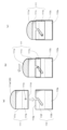
- Figure 7A is a functional explanatory cross-sectional view of a first embodiment of the present invention
- Figure 7B is a functional explanatory cross-sectional view of a second embodiment of the present invention.
- the pair of magnetic joints 11 and 12 can be separated and separated by a force in a direction that bends the back magnetic joint 12 with respect to the axis L that passes through the center of both.
- the joint surface of one or both of the pair of magnetic joint bodies 11, 12 is formed with a slip prevention surface with a friction coefficient ⁇ so as to reinforce the attraction force.
- the joint surface is provided with a rubber viscoelastic layer made of silicone resin or synthetic resin, and these are brought into contact with each other.
- both joint surfaces are made of metal concave-convex complementary joint surfaces, parallel concave grooves and convex strips that mesh with each other, or 2) convex-convex complementary parts that mesh with each other with concentric concave grooves and convex strips.
- the concave-convex parts are made to mesh with wavy parts or that multiple concave-convex parts are made to mesh with each other in a zigzag shape to ensure a constant friction coefficient.
- one concave part and one convex part may be loosely fitted and meshed with each other, or multiple circular protrusions may be arranged to mesh with each other to form a slip prevention part.
- the magnet must have a small joint surface, for example a 5-10 mm diameter magnet joint surface, and must have a magnetic flux density of 3000 Gauss, preferably 4000 Gauss or more. It is recommended to use a rare earth magnet. In particular, a neodymium magnet is used, and it is recommended to form a magnetic circuit MC1 or 2 that can ensure the proper flow of magnetic lines in both magnetic joints by using the yoke body 11c of the front body 11 or the cylindrical yoke bodies 11c and 11b of the front body 11 and the back body 12. When forming the magnetic circuit MC2, sufficient magnetic attraction can be achieved even if a samarcova magnet is used instead of neodymium stone.
- neodymium magnets When using a neodymium magnet, cylindrical neodymium magnets (manufactured by NeoMag) such as N52, N45, N40, N40SH, N40UH, N35H, and N35SH can be used. Both of the pair of magnetic joints 11 and 12 may be magnetic bodies, or one may be a magnetic body and the other a magnetic metal body.
- the magnet is preferably in the form of a columnar rod, since it can be bent and separated from the axis of the pair of magnetic joints 11, 12. Since neodymium magnets rust easily, they are surrounded by a yoke body or silicone rubber or the like. In the case of a yoke body, it is recommended to plate it with a precious metal to give it an ornamental appearance.
- the magnetic body When the magnetic body is surrounded by silicone rubber 12c, it is preferable to form it into a cylindrical shape as shown in Figures 8(a) and (b), and as shown in Figure 8(c), to open the joining surface 12f widely and provide a groove 12g around it so that the magnetic body 12a can be stored, and to provide a circular flange 12d at or near the rear end.
- the hole 12R at the rear end is a punch hole used during molding.
- Figures 9A and 9B are perspective views showing a configuration for reinforcing the first centering function in the magnetic joint type.
- the pair of front and back joint bodies 11, 12 form a first engagement portion consisting of a short convex engagement portion 11d and a shallow concave engagement portion 12f, in which the cylindrical body 11c and cylindrical body 12b of the pair of joint bodies 11, 12 are fitted together by axial movement, and the pair of joint bodies 11, 12 can be released by folding, reinforcing the first centering function.
- 11a indicates the jewelry body
- 11b indicates the magnetic joint body
- 11c indicates the cylindrical body
- 12a indicates the magnetic joint body and 12b indicates the cylindrical body.
- the centering function adopts a modified example of Figure 10. That is, the pair of front and back joints 111, 112 have a shallow annular engagement part on one side, and are fitted together by the axial movement of the cylindrical body 11c and the cylindrical body 12b.
- a shallow annular engagement part 12g is formed at the opening of the cylindrical body 12b, and the bottom part 11d of the cylindrical body 11c is fitted into it to reinforce center alignment.
- FIG. 10 is a perspective view of a structure and joining form that does not have a magnetic joining structure and is only of a physical joining type, (a) shows the state before the front joining body is joined to the back joining body by fitting them together, (b) shows the joined state, (c) shows the locked state, and (d) shows the state in which the locking function is activated and the pet hair is clamped.
- a pet hair ring that is an accessory that is attached to a pet by clamping its body hair, and has a joining part 110 consisting of a front joining body 111 and a back joining body 112, which are a pair of front and back parts that clamp the pet's body hair and are joined with their tips butted against each other, and a decorative part 120 such as a jewelry that is attached to the front joining body 111 and can be seen from the outside when attached,
- the joint 110 consisting of a pair of joints has the following functions necessary for attachment to a pet: 1) a first centering function for centering the pair of joints by pinching the hair when gripping the hair, 2) a second locking function for locking the joined state of the pair of joints, and 3) a third fall-off prevention function for preventing the pair of joints from falling off the pet's hair.
- the front joint 111 of the joint is configured to contain at least a jewelry body 111a such as a gemstone within a cylindrical body 111c
- the front-side joint body 111 or the rear-side joint body 112 on the opposite side thereof is configured to include an elastic body that biases the axial direction of the cylindrical bodies 111c and 112b within the cylindrical bodies 111c and 112b, and is formed into a rod-like shape of a length that can be held by fingertips
- the pair of front and back joint bodies 111, 112 are provided with first engaging portions 111d, 112g which are fitted to each other by the axial movement of the cylindrical body 111c and the cylindrical body 112b, and are configured to be fitted to each other via the first engaging portions, thereby performing the first centering function
- D) the pair of cylindrical bodies 111c, 112b of the joint body are engaged with each other by relative rotation about the axis L, and are provided with a protrusion 111e and a
- the pair of connecting members 111 and 112 are unlocked by rotating the pair of connecting members 111 and 112 relative to the axis L passing through the center of the pair of connecting members 111 and 112, and the pair of connecting members 111 and 112 are separated to form a removable pet hair ring.
- the pair of connecting members 111 and 112 fit together to hold the body hair, and the hair is pressed in the axial direction by the biasing force of the elastic body G to be held in place.
- Figure 11 is a perspective view of a case where both physical and magnetic joining types are used, and has the same configuration as Figure 10 for the physical joining type, but has a shallower fitting type than Figure 10, and shows a type in which the physical fitting and magnetic joining are reinforced. (a) shows the state before the front joining body is joined to the back joining body by fitting, (b) shows the fitted state, and (c) shows the locked state. The same numbers are used for the same parts as Figure 10.
- a pet hair ring is an accessory that is attached to a pet by clamping its body hair, and comprises a joining part 110 consisting of a pair of front and back joints, front joint 111 and back joint 112, which are joined by butting their tips together and hold the pet's body hair, and a decorative part 120 such as jewelry that is attached to front joint 111 and can be seen from the outside when attached.
- Joint 110 consisting of a pair of joints has the following functions necessary for attachment to a pet: 1) a first centering function of aligning the center of the pair of joints by clamping the hair when gripping it, 2) a second locking function of locking the joined state of the pair of joints, and 3) a third fall-off prevention function of preventing the pair of joints from falling off the pet's body hair.
- A) The front joint 111 of the joint is configured by stacking a jewelry body 111a such as a gemstone and a magnetic joint body 111b, and housing them inside a cylindrical body 110c.
- the rear-side joint 112 on the opposite side of the front-side joint is formed into a rod-like shape having a length that can be held by the fingertips, and includes a magnetic joint 112a enclosed in a cylindrical body 112b.
- the pair of front and back joint bodies 111, 112 are provided with first engagement portions 111d, 112g that are fitted to each other by the axial movement of the cylindrical body 111c and the cylindrical body 112b, and are configured to be fitted to each other via the first engagement portions.
- the first centering function is achieved by the magnetic connection of the magnetic joint bodies 111b and 112a of the pair of joint bodies 111, 112 and the engagement of the first engagement portions, D) the cylindrical bodies 111c, 112b of the pair of connected bodies have second engagement portions 111e, 112f (when the magnetic connecting force is used to bias the cylindrical bodies in the axial direction, the notches may be horizontal) that prevent the cylindrical bodies from moving in the axial direction by relative rotation about the axis, and the magnetic connection of the pair of magnetic connected bodies engages with the second engagement portions of the pair of cylindrical bodies 111c, 112b to perform a second locking function that prevents the cylindrical bodies 111c, 112b from moving in the axial direction by the magnetic connecting force of the pair of magnetic connected bodies 111, 112, and E) the pair of cylindrical bodies 111c, 112b are biased in the axial direction by the magnetic connecting force of the pair of magnetic connected bodies 111, 112 together with the relative movement about the axis, and have a third anti-falling function
- the present invention provides pet earrings as a pet accessory, but also provides a new way of using pet accessories, called double wearing, in which the pet owner wears the same pet accessory as the pet (see Figure 1 (b)).
Landscapes
- Life Sciences & Earth Sciences (AREA)
- Environmental Sciences (AREA)
- Animal Husbandry (AREA)
- Biodiversity & Conservation Biology (AREA)
- Adornments (AREA)
Priority Applications (1)
| Application Number | Priority Date | Filing Date | Title |
|---|---|---|---|
| JP2025532371A JPWO2025013313A1 (cg-RX-API-DMAC7.html) | 2023-07-12 | 2024-01-20 |
Applications Claiming Priority (2)
| Application Number | Priority Date | Filing Date | Title |
|---|---|---|---|
| JP2023114684 | 2023-07-12 | ||
| JP2023-114684 | 2023-07-12 |
Publications (1)
| Publication Number | Publication Date |
|---|---|
| WO2025013313A1 true WO2025013313A1 (ja) | 2025-01-16 |
Family
ID=94214918
Family Applications (1)
| Application Number | Title | Priority Date | Filing Date |
|---|---|---|---|
| PCT/JP2024/001550 Ceased WO2025013313A1 (ja) | 2023-07-12 | 2024-01-20 | ペットに体毛を介して取り付けるペット用ヘアリング |
Country Status (2)
| Country | Link |
|---|---|
| JP (1) | JPWO2025013313A1 (cg-RX-API-DMAC7.html) |
| WO (1) | WO2025013313A1 (cg-RX-API-DMAC7.html) |
Citations (5)
| Publication number | Priority date | Publication date | Assignee | Title |
|---|---|---|---|---|
| JPH0355720U (cg-RX-API-DMAC7.html) * | 1989-10-03 | 1991-05-29 | ||
| JP3095816U (ja) * | 2003-02-10 | 2003-08-22 | 潤 佐藤 | 磁着する二つの面にゴム等の弾性体の物を、はり付けた磁石。 |
| JP2007014644A (ja) * | 2005-07-08 | 2007-01-25 | Machiko Ikenoue | ヘアアクセサリー |
| US20120103014A1 (en) * | 2010-10-27 | 2012-05-03 | Evangeline Sunday Monroe | Friction Based Forehead and Hair Jewelry System |
| JP2012187011A (ja) * | 2011-03-09 | 2012-10-04 | Art Climb Co Ltd | ペット飾り取付装置および取付方法 |
-
2024
- 2024-01-20 JP JP2025532371A patent/JPWO2025013313A1/ja active Pending
- 2024-01-20 WO PCT/JP2024/001550 patent/WO2025013313A1/ja not_active Ceased
Patent Citations (5)
| Publication number | Priority date | Publication date | Assignee | Title |
|---|---|---|---|---|
| JPH0355720U (cg-RX-API-DMAC7.html) * | 1989-10-03 | 1991-05-29 | ||
| JP3095816U (ja) * | 2003-02-10 | 2003-08-22 | 潤 佐藤 | 磁着する二つの面にゴム等の弾性体の物を、はり付けた磁石。 |
| JP2007014644A (ja) * | 2005-07-08 | 2007-01-25 | Machiko Ikenoue | ヘアアクセサリー |
| US20120103014A1 (en) * | 2010-10-27 | 2012-05-03 | Evangeline Sunday Monroe | Friction Based Forehead and Hair Jewelry System |
| JP2012187011A (ja) * | 2011-03-09 | 2012-10-04 | Art Climb Co Ltd | ペット飾り取付装置および取付方法 |
Also Published As
| Publication number | Publication date |
|---|---|
| JPWO2025013313A1 (cg-RX-API-DMAC7.html) | 2025-01-16 |
Similar Documents
| Publication | Publication Date | Title |
|---|---|---|
| CN1395896A (zh) | 磁性带扣 | |
| US20030229974A1 (en) | Concealed secure magnetic clasp | |
| JP6326529B2 (ja) | 襟固定器具 | |
| US8621887B1 (en) | Interchangeable earring for individuals with pierced sensitive ears | |
| US20160174669A1 (en) | Variable ornament assembly | |
| GB2243645A (en) | Releasable fastening | |
| US20180020789A1 (en) | Jewelry with Threaded Head and Improved Magnetic Assembly | |
| US20050138963A1 (en) | Jewelry assembly | |
| JP7119067B2 (ja) | 幾何学的立体用のモジュラ式フレーム | |
| US20050178154A1 (en) | Decorative clasp system | |
| JP2012147980A (ja) | 磁石を使用したバックル | |
| JP3243923U (ja) | ペットに体毛を介して取り付けるペット用ヘアリング | |
| AU2017203487A1 (en) | Jewelry with a magnetic and a non-magnetic assembly | |
| JP3055446U (ja) | 磁石付止め具 | |
| JP7533975B2 (ja) | 装身具とその製造方法 | |
| US20080209693A1 (en) | Magnetic Clasp | |
| JPH10179219A (ja) | 装身具用留金 | |
| US20140363227A1 (en) | Article, Interchangeable Component, And System | |
| JP3134460U (ja) | 装身具用連結金具 | |
| JP2003019008A (ja) | バッジおよび合成樹脂部材に対する磁石の取付方法 | |
| JP2010119336A (ja) | 接木用クリップ | |
| JP2006204511A (ja) | ペンダント | |
| JP5439043B2 (ja) | アクセサリ用クラスプ | |
| JP3208664U (ja) | 装飾品接合部材 | |
| JP2019154873A (ja) | 連結具及びそれを備えた連結体 |
Legal Events
| Date | Code | Title | Description |
|---|---|---|---|
| 121 | Ep: the epo has been informed by wipo that ep was designated in this application |
Ref document number: 24839211 Country of ref document: EP Kind code of ref document: A1 |
|
| ENP | Entry into the national phase |
Ref document number: 2025532371 Country of ref document: JP Kind code of ref document: A |
|
| WWE | Wipo information: entry into national phase |
Ref document number: 2025532371 Country of ref document: JP |
|
| NENP | Non-entry into the national phase |
Ref country code: DE |
|
| 122 | Ep: pct application non-entry in european phase |
Ref document number: 24839211 Country of ref document: EP Kind code of ref document: A1 |