WO2025013301A1 - 内燃機関制御装置 - Google Patents
内燃機関制御装置 Download PDFInfo
- Publication number
- WO2025013301A1 WO2025013301A1 PCT/JP2023/025957 JP2023025957W WO2025013301A1 WO 2025013301 A1 WO2025013301 A1 WO 2025013301A1 JP 2023025957 W JP2023025957 W JP 2023025957W WO 2025013301 A1 WO2025013301 A1 WO 2025013301A1
- Authority
- WO
- WIPO (PCT)
- Prior art keywords
- internal combustion
- correction
- combustion engine
- pulsation
- value
- Prior art date
- Legal status (The legal status is an assumption and is not a legal conclusion. Google has not performed a legal analysis and makes no representation as to the accuracy of the status listed.)
- Ceased
Links
Images
Classifications
-
- F—MECHANICAL ENGINEERING; LIGHTING; HEATING; WEAPONS; BLASTING
- F02—COMBUSTION ENGINES; HOT-GAS OR COMBUSTION-PRODUCT ENGINE PLANTS
- F02D—CONTROLLING COMBUSTION ENGINES
- F02D41/00—Electrical control of supply of combustible mixture or its constituents
- F02D41/02—Circuit arrangements for generating control signals
- F02D41/18—Circuit arrangements for generating control signals by measuring intake air flow
-
- F—MECHANICAL ENGINEERING; LIGHTING; HEATING; WEAPONS; BLASTING
- F02—COMBUSTION ENGINES; HOT-GAS OR COMBUSTION-PRODUCT ENGINE PLANTS
- F02D—CONTROLLING COMBUSTION ENGINES
- F02D45/00—Electrical control not provided for in groups F02D41/00 - F02D43/00
-
- G—PHYSICS
- G01—MEASURING; TESTING
- G01F—MEASURING VOLUME, VOLUME FLOW, MASS FLOW OR LIQUID LEVEL; METERING BY VOLUME
- G01F1/00—Measuring the volume flow or mass flow of fluid or fluent solid material wherein the fluid passes through a meter in a continuous flow
- G01F1/68—Measuring the volume flow or mass flow of fluid or fluent solid material wherein the fluid passes through a meter in a continuous flow by using thermal effects
-
- G—PHYSICS
- G01—MEASURING; TESTING
- G01F—MEASURING VOLUME, VOLUME FLOW, MASS FLOW OR LIQUID LEVEL; METERING BY VOLUME
- G01F1/00—Measuring the volume flow or mass flow of fluid or fluent solid material wherein the fluid passes through a meter in a continuous flow
- G01F1/72—Devices for measuring pulsing fluid flows
Definitions
- an air flow measuring device has been placed in the intake pipe of the internal combustion engine to detect the intake air flow rate of the internal combustion engine, and the amount of fuel injection has been controlled using the air flow rate measured by the air flow measuring device.
- improving the exhaust performance of internal combustion engines has become an important issue, and it has become common to convert the output of each sensor into a digital value and control the amount of fuel injection using a digital calculation device.
- air flow measurement devices that have a backflow detection function.
- air flow measurement devices with a backflow detection function are thermal type, and generally have the characteristic that the output is high on the forward flow side and low on the reverse flow side.
- Thermal air flow measuring devices are known to have a response delay caused by their own thermal capacity and the effect of a nonlinear correspondence between the air flow rate and the output of the thermal air flow detection device, which can cause errors between the average flow rate of air actually drawn into the cylinder and the average air flow rate calculated by the digital calculation device during pulsation.
- Patent Document 1 discloses a technology that has multiple tables for converting the signal from an air flow sensor into an air flow rate, and selects a conversion table according to a state value that directly or indirectly indicates the state of the air flow pulsation occurring in the air passage.
- the present invention was made in consideration of the above problems, and aims to provide an internal combustion engine control device that can perform appropriate pulsation correction, particularly in operating regions where pulsation error is large.
- the internal combustion engine control device of the present invention is an internal combustion engine control device that includes an amplitude reading unit that reads the amplitude of the output value of a flow sensor that measures the amount of intake air flowing through the intake passage of the internal combustion engine, a memory unit that stores a correction map associated with the pulsation characteristics of the internal combustion engine, a correction value setting unit that sets a control correction value associated with the output value of the flow sensor based on the correction map, a pulsation correction determination unit that compares the value of a parameter indicating the operating state of the internal combustion engine with a predetermined threshold value to determine whether or not to correct the output value of the flow sensor, and an intake air volume calculation unit that calculates the control intake air volume based on the determination of the pulsation correction determination unit, and the intake air volume calculation unit outputs the control correction value as the control intake air volume when the pulsation correction determination unit determines that correction is required.
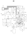
- FIG. 1 is a schematic diagram showing a physical configuration of a control device for an internal combustion engine according to an embodiment of the present invention
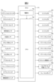
- FIG. 2 is a block diagram illustrating the inputs and outputs of an engine control unit.
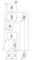
- FIG. 2 is a functional block diagram showing a functional configuration of the internal combustion engine control device.
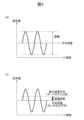
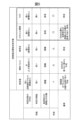
- 1 is a graph for explaining a pulsation rate and a pulsation error. A list of parameters that can be considered to initiate pulsation correction.
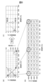
- 4 is a graph showing a correction map used in the present invention and pulsation errors before and after correction. 4 is a flowchart showing a process executed by a control device in the embodiment.
- FIG. 1 is a diagram showing a control device for an internal combustion engine according to the present invention
- FIG. 2 is a diagram explaining inputs and outputs of the engine control unit.
- the internal combustion engine 65 is an in-line 4-cylinder internal combustion engine with the so-called MPI (multi-cylinder fuel injection) system, and the air drawn into the internal combustion engine 65 passes through an air cleaner 60, and then through an intake passage 64 consisting of an intake duct 61, a collector 62, and an intake pipe 63, before flowing into the combustion chamber 67a of each cylinder 67.
- MPI multi-cylinder fuel injection
- An intake valve 92 is provided in the intake port that communicates with the downstream portion of the intake passage 64 to open and close the space between the intake passage 64 and the combustion chamber 67a.
- the amount of incoming air is detected by an airflow sensor (thermal airflow measuring device) 2 located downstream of the air cleaner 60.
- the airflow sensor 2 has a heating resistor (not shown), which outputs a signal corresponding to the intake air volume, as well as an intake temperature signal measured by an intake temperature sensor 2a using a thermistor.
- This hot wire type airflow sensor 2 is highly responsive, reacts accurately to the pulsations generated in the intake passage 64, and outputs a pulsating waveform as an output signal.
- the electronic throttle valve 40 is provided midway through the intake passage 64, and by moving it in the closing direction, the opening area of the intake passage 64 can be narrowed, which has the effect of making it difficult for pulsation to occur within the intake passage 64 (see, for example, FIG. 11).
- the electronic throttle valve 40 is driven by a throttle drive motor 42 based on a signal from the engine control unit 71.
- the electronically controlled throttle valve 40 is fitted with a throttle opening sensor 1 that detects the opening, and the sensor signal is input to a control unit 71, which performs feedback control of the throttle opening TVO of the throttle valve 40, detection of the fully closed position, and detection of acceleration.
- the feedback target opening is determined from the driver's accelerator depression amount determined by the accelerator opening sensor 14 and the idle speed control, i.e., ISC control.
- the internal combustion engine 65 is equipped with a variable valve timing mechanism 91 as a variable valve mechanism.
- the variable valve timing mechanism 91 is driven based on a drive signal from the engine control unit 71, and has a configuration that allows adjustment of the opening and closing timing, which is the valve timing, and performs feedback control toward a target cam angle.
- the valve timing of the intake valve 92 is changed by the variable valve timing mechanism 91, air may be blown back from the combustion chamber 67a into the intake pipe 63.
- Blowback occurs when the intake valve 92 is closed early or late (see, for example, Figure 13).
- the valve closing timing is early, the intake valve 92 opens before the exhaust stroke ends, causing blowback from the combustion chamber 67a into the intake passage 64.
- the valve closing timing is late, the intake valve 92 closes late, causing air in the combustion chamber 67a during the compression stroke to be blown back into the intake passage 64.
- blowback occurs periodically, and the amount of pulsation changes depending on the intake valve closing timing (see, for example, Figure 13).
- a pulse is output from the crank angle sensor 7 attached to the crankcase of the internal combustion engine 65 at every predetermined crank angle, and input to the engine control unit 71.
- the accelerator opening sensor 14 detects the amount of depression of the accelerator pedal 15, and thereby detects the torque required by the driver. Fuel is sucked from the fuel tank 21 by the fuel pump 20, pressurized, and adjusted to a constant pressure by the pressure regulator 22, and injected into the intake pipe 63 from the injector 23.
- a water temperature sensor 3 for detecting the cooling water temperature is attached to the cylinder block 66, and the sensor signal is input to a control unit 71, which detects the warm-up state of the internal combustion engine 65 and increases the amount of fuel injection, corrects the ignition timing, turns the radiator fan 75 on and off, and sets the target rotation speed during idle. Also, in order to calculate the target rotation speed during idle and the load correction amount, an air conditioner switch 18 for monitoring the state of the air conditioner clutch and a neutral switch 17 built into the transmission for monitoring the state of the drive system are attached.
- the air-fuel ratio sensor 8 is attached to an exhaust pipe 81 that is connected to an exhaust port 80 of the internal combustion engine 65, and outputs a signal corresponding to the oxygen concentration of the exhaust gas.
- the signal from the air-fuel ratio sensor 8 is input to a control unit 71, which is a control device, and adjustments are made to the fuel injection pulse width, etc., so that the target air-fuel ratio required according to the driving conditions is achieved.
- the engine control unit 71 is composed of a CPU 78 and a power supply IC 79.
- the signals input to the engine control unit 71 are summarized as follows: signals from the airflow sensor 2, the built-in intake temperature sensor 2a, the crank angle sensor 7, the throttle opening sensor 1, the air-fuel ratio sensor 8, and the water temperature sensor 3 are input.
- the engine control unit 71 reads the voltage of the air flow sensor 2 at regular intervals. In this embodiment, the reading is done every 10 ms, so aliasing must be taken into consideration when pulsation occurs. It is also proportional to the pulsation frequency of the air flow rate and the engine speed.
- the output signal from the engine control unit 71 is output to the power transistor 30, which includes the injector 23, the fuel pump 20, and the ignition switch of the spark plug 33.
- the engine control unit 71 has a storage means for storing a plurality of conversion tables for converting the signal from the airflow sensor 2 into an airflow rate. Then, by executing the airflow measurement program, a selection means for selecting a conversion table to be used for conversion from the plurality of conversion tables stored in the storage means and a conversion means for converting the signal from the airflow sensor 2 into an airflow rate using the conversion table selected by the selection means are realized.
- pulsation occurs due to the resonance between the vibration of air pressure that occurs with the period of the up and down movement of the piston and the vibration due to the natural frequency of the intake passage 64. Also, in an engine with a high expansion ratio cycle in which the timing of opening and closing the intake valve 92 is slow, backflow occurs, causing larger pulsation. Also, if the timing of opening the intake valve 92 is early or the overlap is large, backflow occurs due to the exhaust pressure, causing larger pulsation.
- FIG. 3 is a functional block diagram showing the functional configuration of an engine control unit (internal combustion engine control device) 71 according to this embodiment.
- the control device includes an amplitude reading unit 711, a memory unit 712 that stores a pulsation correction map, a correction value setting unit 713, a pulsation correction determination unit 714, and an intake air amount calculation unit 715.
- the amplitude reading unit 711 reads the amplitude of the output value of a flow sensor that measures the amount of intake air flowing through the intake passage of an internal combustion engine. More specifically, it reads the amplitude and further calculates the pulsation rate and pulsation error of the flow sensor.
- pulsation rate refers to a value that indicates the proportion of AC included in the output DC (pulsating flow), and is expressed as (amplitude/average flow rate) using the air volume over time graph shown in Figure 4 (a).
- Pulsation error is a phenomenon in which an error occurs between the average flow rate of air actually drawn into the cylinder during pulsation and the average value of the air flow rate calculated by the digital calculation device due to response delays caused by its own heat capacity and the influence of the nonlinear correspondence between the air flow rate and the output of the airflow sensor 2, and is expressed as (average flow rate - true average flow rate)/true average flow rate, as shown in Figure 4 (b).
- the true average flow rate refers to the actual flow rate measured upstream of the surge tank, compared to the average flow rate, which is the average of the flow sensor outputs.
- the present invention has been made to perform judgment control so that pulsation correction does not become unnecessarily effective when the pulsation error is large.
- the parameters of the internal combustion engine are used to judge the pulsation, as described later, and candidate parameters for the judgment are shown in Figure 5.
- the judgment targets for starting pulsation correction include the air volume, injection pulse, intake pressure, throttle opening, and VTC (Valve Timing Control).
- the parameters to be used to determine the start of pulsation it is preferable to set these parameters according to the operating state of the internal combustion engine.
- the throttle opening and VTC are particularly preferable as the parameters to be used to determine the start of pulsation correction.
- the threshold values for these parameters which serve as the criteria for judgment, can be set arbitrarily depending on various operating conditions, but it is preferable to set the threshold value to a value that eliminates the nonlinear relationship between the air flow rate and the output of the air flow sensor 2, for example.
- the pulsation correction map stored in the memory unit 712 is a correction map associated with the pulsation characteristics of the internal combustion engine. Details of this will be explained using Figure 6.
- Fig. 6(a) is a graph showing the relationship (pulsation characteristics) between the pulsation rate and the pulsation error (left axis) when the rotation speed of the internal combustion engine used in this embodiment is 4000 (rpm), and the correction value (right axis) associated with the pulsation characteristic. Note that the pulsation error after the pulsation rate reaches 100% is omitted because it is the same value as when the pulsation rate is 100%.
- a correction map such as that shown in FIG. 6(b) is applied to the graph in FIG. 6(a). Then, as shown in the corrected graph in FIG. 6(c), it can be seen that the pulsation rate is nearly 0% for all pulsation rates. In this way, by applying a correction map such as that of this embodiment, it is possible to reduce the pulsation error to nearly 0% even in areas where the pulsation rate is likely to be large.
- the correction value setting unit 713 sets a control correction value that is associated with the output value of the flow sensor based on the correction map. That is, the correction value setting unit 713 reads the correction map in FIG. 6(b) based on the rotation speed 101 received from the accelerator opening sensor 14, and sets and stores the numerical value obtained by multiplying the air amount 102, which is the output value of the flow sensor, by the correction value.
- the pulsation correction determination unit 714 compares the value of a parameter indicating the operating state of the internal combustion engine with a predetermined threshold value to determine whether or not to correct the output value of the flow sensor. It does this by selecting one of the various parameters shown in FIG. 5 described above, comparing the parameter value with a predetermined threshold value, and determining whether or not it is necessary to correct the output value of the flow sensor.
- the intake air volume calculation unit 715 calculates the control intake air volume based on the judgment of the pulsation correction judgment unit 714. Specifically, in this embodiment, if the pulsation correction judgment unit 714 judges that correction is necessary, it outputs the value set by the correction value setting unit 713 as the corrected air volume 104 as is, and if it judges that correction is not necessary, it outputs the value 102 output by the flow sensor as is as the corrected air volume 104.
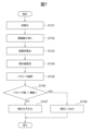
- FIG. 7 is a flowchart showing the process executed by the control device in this embodiment.
- step S101 an initialization process is performed to clear information stored in the memory of the engine control unit 71.
- step S102 the amplitude reading section 711 of the engine control unit 71 receives the output value of the flow sensor and reads the amplitude, and in step S103 calculates the pulsation rate and pulsation error.
- step S104 the correction value setting unit 713 receives the rotation speed 101 from the accelerator opening sensor 14 and refers to the correction map 712, and sets a correction value by multiplying the corresponding correction value by the air volume 102 read by the amplitude reading unit 711.
- step S105 the pulsation correction determination unit 714 selects one of the multiple parameters shown in FIG. 5 as the internal combustion engine parameter 103. Then, in step S106, the value of the selected parameter is compared with a predetermined threshold value to determine whether correction is required, and the result is sent to the intake air volume calculation unit 715. Specifically, the value of the parameter is compared with the threshold value, and the result is sent.
- step S106 If the result of step S106 is No, the intake air volume calculation unit 715 does not make any correction (step S106), i.e., outputs the value output by the flow sensor as is. If the result of step S106 is Yes, the intake air volume calculation unit 715 corrects the value output by the flow sensor and outputs it (step S107).
- the internal combustion engine parameters are compared with threshold values to determine whether or not to perform correction.
- the intake air amount calculation unit 715 outputs the value set by the correction value setting unit 713 as the corrected air amount 104.
- the values before and after correction may differ significantly, causing the output to become discontinuous, which may be detected as an abnormality.
- the intake air volume calculation unit 715 can output, as a correction value, a value obtained by interpolating the value output by the flow sensor and the correction value set by the correction value setting unit 713.
- the interpolation calculation here is, for example, a weighting calculation.
- the intake air volume calculation unit 715 may calculate a corrected output value using a time constant that changes the value output by the flow sensor over time to the correction value set by the correction value setting unit 713.
- the correction map may be stored in the memory as a basic correction value map that is pre-adapted to the nonlinear region of the flow sensor, or may be stored in the memory as a neural network model that includes an input layer that provides parameters indicating the operating state of the internal combustion engine as explanatory variables, an intermediate layer connected to the input layer, and each unit of an output layer, with weights, biases, and activation functions pre-set in the intermediate layer units, and the correction map set in the output layer.
- the internal combustion engine control device is an internal combustion engine control device that includes an amplitude reading unit that reads the amplitude of the output value of a flow sensor that measures the amount of intake air flowing through an intake passage of an internal combustion engine, a memory unit that stores a correction map associated with the pulsation characteristics of the internal combustion engine, a correction value setting unit that sets a control correction value associated with the output value of the flow sensor based on the correction map, a pulsation correction determination unit that compares the value of a parameter indicating the operating state of the internal combustion engine with a predetermined threshold value to determine whether or not to correct the output value of the flow sensor, and an intake air volume calculation unit that calculates a control intake air volume based on the determination of the pulsation correction determination unit, and the intake air volume calculation unit outputs the control correction value as the control intake air volume when the pulsation correction determination unit determines that correction is required.
- the above configuration makes it possible to perform appropriate pulsation correction, especially in operating regions where pulsation errors are large.
- the pulsation correction determination unit adjusts a parameter indicating the operating state of the internal combustion engine, which is the criterion for determining whether or not to correct the output value of the flow sensor, according to the operating state of the internal combustion engine. This makes it possible to select the optimal parameter depending on the state of the internal combustion engine at any given time and determine whether or not pulsation correction is required.
- the intake air volume calculation unit outputs a value obtained by interpolating the control correction value and the output value of the flow sensor as the intake air volume, or outputs the intake air volume by changing the control correction value over time. This makes it possible to prevent the output value from becoming discontinuous before and after correction, which would be detected as an abnormality.
- the correction map is stored in the memory as a basic correction value map that is pre-adapted to the nonlinear region of the flow sensor, or is stored in the memory as a neural network model that includes an input layer that provides parameters indicating the operating state of the internal combustion engine as explanatory variables, an intermediate layer connected to the input layer, and each unit of the output layer, with weights, biases, and activation functions pre-set in the intermediate layer units, and the correction map set in the output layer. This allows the correction map to be updated using an AI model, making it possible to output optimal correction values.
- the present invention is not limited to the above-described examples, and various modifications are possible.
- the above-described examples have been described in detail to clearly explain the present invention, and the present invention is not necessarily limited to an embodiment that includes all of the configurations described. It is also possible to replace part of the configuration of one embodiment with the configuration of another embodiment. It is also possible to add the configuration of another embodiment to the configuration of one embodiment. It is also possible to delete part of the configuration of each embodiment, or to add or replace other configurations.
Landscapes
- Engineering & Computer Science (AREA)
- Chemical & Material Sciences (AREA)
- Combustion & Propulsion (AREA)
- Mechanical Engineering (AREA)
- General Engineering & Computer Science (AREA)
- Physics & Mathematics (AREA)
- Fluid Mechanics (AREA)
- General Physics & Mathematics (AREA)
- Combined Controls Of Internal Combustion Engines (AREA)
Abstract
本発明に係る内燃機関制御装置は、内燃機関の吸気流路を流れる吸入空気量を測定する流量センサの出力値の振幅を読み取る振幅読み取り部と、内燃機関の脈動特性に対応付けられた補正マップを記憶する記憶部と、補正マップに基づいて流量センサの出力値に対応付けられた制御用補正値を設定する補正値設定部と、内燃機関の運転状態を示すパラメータの値と所定の閾値とを比較して流量センサの出力値を補正するか否か判定する脈動補正判定部と、脈動補正判定部の判定に基づいて制御用吸入空気量を演算する吸入空気量演算部と、を備える内燃機関制御装置であって、吸入空気量演算部は、脈動補正判定部が補正要と判定した際に、制御用補正値を制御用吸入空気量として出力する。
Description
本発明は、内燃機関の制御装置に関する。
従来から、自動車などの内燃機関の制御装置では、内燃機関の吸入空気流量を検出するために、内燃機関の吸気管に空気流量測定装置を配置し、その空気流量測定装置によって測定された空気流量を用いて燃料噴射量を制御することが行われている。そして、近年では、内燃機関の排気性能の向上が重要な課題となっており、各センサの出力をディジタル値に変換し、ディジタル演算装置によって燃料噴射量の制御を行うことが一般的になっている。
内燃機関では、ピストンの上下運動により発生する空気圧力振動と、吸気管の固有振動数による振動の共鳴により、脈動と呼ばれる気柱現象が発生する。吸気管内に設置されたスロットルバルブの開度を大きくすると、脈動の振幅は大きくなる。
通常はエアクリーナからシリンダ内に空気が流れ込むが、内燃機関の吸気弁からエアクリーナの方に流れることがあり、この現象は逆流と呼ばれている。逆流は、逆流検知機能を備えていない空気流量測定装置で測定すると、流れの方向に関係なく、順流として流量を測定し、空気流量に誤差が発生してしまう。
この問題を解決するために、逆流検知機能を持つ空気流量測定装置も存在する。一般的に逆流検知機能を持つ空気流量測定装置は、熱式のものが多く、順流側の出力が高く、逆流側の出力が低くなる特性を持つものが一般的である。
熱式空気流量測定装置は、自分自身の熱容量に起因する応答遅れや、空気流量と熱式空気流量検出装置の出力の間に非線形の対応関係による影響により、脈動時において、実際にシリンダに吸入される空気の平均流量と、ディジタル演算装置で演算される空気流量の平均値の間に誤差が生じることが知られている。
更に、吸気管の中を流れる空気流が逆流する際の流体の挙動は、壁面付近の流れと、主流との間で、位相のずれが発生することが知られている。逆流検知可能な熱式空気流量検出装置のエレメント部は平面なものが多く、主流と壁面付近の流れに類似の挙動が発生し誤差が発生する。
前記影響の中で、脈動発生時に正確な空気流量を得る方法として、特許文献1には、空気流量センサの信号を空気流量に変換するテーブルを複数備え、空気通路内に発生する空気流の脈動の状態を直接又は間接的に示す状態値に応じて変換テーブルの選択を行う技術が開示されている。
しかしながら、更に内燃機関には過渡応答性があり、脈動誤差が大きい場合に過渡と脈動いずれによるものか判別をすることが困難であった。
本発明は上記課題を鑑みてなされたものであり、特に脈動誤差が大きくなる運転領域において適切な脈動補正を行うことのできる内燃機関制御装置を提供することを目的とする。
上記課題を解決するために、本発明に係る内燃機関制御装置は、内燃機関の吸気流路を流れる吸入空気量を測定する流量センサの出力値の振幅を読み取る振幅読み取り部と、内燃機関の脈動特性に対応付けられた補正マップを記憶する記憶部と、補正マップに基づいて流量センサの出力値に対応付けられた制御用補正値を設定する補正値設定部と、内燃機関の運転状態を示すパラメータの値と所定の閾値とを比較して流量センサの出力値を補正するか否か判定する脈動補正判定部と、脈動補正判定部の判定に基づいて制御用吸入空気量を演算する吸入空気量演算部と、を備える内燃機関制御装置であって、吸入空気量演算部は、脈動補正判定部が補正要と判定した際に、制御用補正値を制御用吸入空気量として出力する。
本発明を用いることによって、特に脈動誤差が大きくなる運転領域において適切な脈動補正を行うことが可能になる。
本発明に関連する更なる特徴は、本明細書の記述、添付図面から明らかになるものである。また、上記した以外の課題、構成及び効果は、以下の実施例の説明により明らかにされる。
本発明に関連する更なる特徴は、本明細書の記述、添付図面から明らかになるものである。また、上記した以外の課題、構成及び効果は、以下の実施例の説明により明らかにされる。
以下、本発明の実施の形態について図面を参照しながら説明する。
図1は、本発明の内燃機関の制御装置を示す図、図2は、エンジンコントロールユニットの入力および出力を説明する図である。
図1は、本発明の内燃機関の制御装置を示す図、図2は、エンジンコントロールユニットの入力および出力を説明する図である。
内燃機関65は、いわゆるMPI(多気筒燃料噴射)方式の直列4気筒内燃機関であり、内燃機関65に吸入される空気は、エアクリーナ60を通過し、吸気ダクト61、コレクタ62、吸気管63からなる吸気通路64を経て、各気筒67の燃焼室67a内に流入される。
吸気通路64の下流部分に連通する吸気ポートには、吸気通路64と燃焼室67aとの間を開閉するための吸気弁92が配設されている。流入空気量は、エアクリーナ60の下流に配置されたエアフローセンサ(熱式空気流量測定装置)2によって検出される。
エアフローセンサ2は、図示していない発熱抵抗体を有しており、その発熱抵抗体から吸入空気量に相当する信号が出力されるとともに、サーミスターを用いた吸気温度センサ2aで計測される吸気温度信号が出力される。このホットワイヤ式のエアフローセンサ2は、応答性が高く、吸気通路64で発生した脈動に対し精度良く反応し、出力信号には脈動波形が出力される。
電制スロットルバルブ40は、吸気通路64の通路途中に設けられており、閉じ方向に動かすことにより、吸気通路64の開口面積を絞ることができ、吸気通路64内で脈動が発生しにくくする効果を有する(例えば、図11を参照)。電制スロットルバルブ40は、エンジンコントロールユニット71からの信号に基づいてスロットル駆動モータ42により駆動される。
電制スロットルバルブ40には、開度を検出するスロットル開度センサ1が取り付けられており、このセンサ信号はコントロールユニット71に入力され、スロットルバルブ40のスロットル開度TVOのフィードバック制御や、全閉位置の検出及び加速の検出等を行う。尚、フィードバックの目標開度は、アクセル開度センサ14で求まるドライバーのアクセル踏み込み量とアイドル回転数制御すなわちISC制御分とから求まるものである。
内燃機関65は、可変動弁機構としてバルブタイミング可変機構91を備えている。バルブタイミング可変機構91は、エンジンコントロールユニット71から駆動信号に基づいて駆動され、バルブタイミングである開閉時期を調整可能な構成を有しており、目標カム角度に向けて、フィードバック制御を行う。バルブタイミング可変機構91により、吸気弁92のバルブタイミングが変化すると、燃焼室67aから吸気管63への吹き返しが発生する場合がある。
吹き返しは、吸気弁92の閉弁タイミングが早い場合と遅い場合に発生する(例えば、図13を参照)。閉弁タイミングが早い場合は、排気工程が終了する前に吸気弁92が開き、燃焼室67a内から吸気通路64に吹き返しが発生することによる。そして、閉弁タイミングが遅い場合は、吸気弁92の遅閉じにより、圧縮工程中の燃焼室67a内の空気が吸気通路64に吹き返されることによるものである。その結果、吹き返しは周期的に発生するために、吸気閉弁タイミングに応じて脈動量が変化する(例えば図13を参照)。
内燃機関65のクランクケースに取り付けられたクランク角センサ7からは、所定のクランク角毎にパルスが出力されて、エンジンコントロールユニット71に入力される。アクセル開度センサ14では、アクセルペダル15の踏み込み量を検出し、それによって運転者の要求トルクを検出する。燃料は、燃料タンク21から燃料ポンプ20で吸引、加圧され、プレッシャレギュレータ22により一定圧力に調圧され、インジェクタ23から吸気管63内に噴射される。
シリンダブロック66には、冷却水温を検出するための水温センサ3が取り付けられており、このセンサ信号は、コントロールユニット71に入力され、内燃機関65の暖機状態を検出し、燃料噴射量の増量や点火時期の補正及びラジエータファン75のON/OFFやアイドル時の目標回転数の設定を行う。また、アイドル時の目標回転数や、負荷補正量の算出するために、エアコンクラッチの状態をモニターするエアコンスイッチ18、駆動系の状態をモニターするトランスミッションに内蔵されたニュートラルスイッチ17が取り付けられている。
空燃比センサ8は、内燃機関65の排気ポート80に連通して接続された排気管81に装着されており、排気ガスの酸素濃度に応じた信号を出力する。空燃比センサ8からの信号は、制御装置であるコントロールユニット71に入力され、運転状況に応じて求められる目標空燃比になるように、燃料噴射パルス幅の調整等がなされる。
エンジンコントロールユニット71は、図2に示すように、CPU78と、電源IC79とから構成されている。ここで、エンジンコントロールユニット71に入力する信号等について、同図を用いて整理すると、エアフローセンサ2と内蔵吸気温度センサ2a、クランク角センサ7、スロットル開度センサ1、空燃比センサ8、水温センサ3からの信号などが入力される。
エンジンコントロールユニット71は、一定周期毎にエアフローセンサ2の電圧を読み込む。本実施の形態では、10msで読み込んでいるため、脈動発生時にはエリアシングを考慮する必要がある。また、空気流量の脈動周波数とエンジン回転数に比例している。エンジンコントロールユニット71からの出力信号は、インジェクタ23、燃料ポンプ20、点火プラグ33の点火スイッチなどがあるパワートランジスタ30に出力される。
エンジンコントロールユニット71は、エアフローセンサ2からの信号を空気流量に変換するための複数の変換テーブルを記憶する記憶手段を有している。そして、空気流量測定プログラムの実行により、記憶手段に記憶されている複数の変換テーブルの中から変換に使用する変換テーブルを選択する選択手段と、選択手段により選択された変換テーブルを使用してエアフローセンサ2の信号を空気流量に変換する変換手段が実現される。
上述の内燃機関65では、ピストンの上下運動の周期で発生する空気圧力の振動と、吸気通路64の固有振動数による振動の共鳴により、脈動が発生する。また、吸気弁92の開閉タイミングが遅い高膨張比サイクルのエンジンでは逆流が発生するため、より大きな脈動が発生する。また、吸気弁92の開くタイミングが早い場合や、オーバーラップが大きい場合にも、排気の圧力などにより逆流が発生するため、より大きな脈動が発生する。
図3は、本実施例に係るエンジンコントロールユニット(内燃機関制御装置)71の機能構成を示す機能ブロック図である。図3に示すように、制御装置は、振幅読み取り部711、脈動補正マップを記憶した記憶部712、補正値設定部713、脈動補正判定部714、及び吸入空気量演算部715を備える。
振幅読み取り部711は、内燃機関の吸気流路を流れる吸入空気量を測定する流量センサの出力値の振幅を読み取る。より具体的には、振幅を読み取り、さらに流量センサの脈動率及び脈動誤差を演算する。
ここで、脈動率とは、出力された直流(脈流)に含まれる交流分の割合を表わす数値のことを指し、図4(a)に示す空気量の経時グラフを用いて、(振幅/平均流量)で表される。また、脈動誤差とは、自分自身の熱容量に起因する応答遅れや、空気流量とエアフローセンサ2の出力との間に非線形の対応関係による影響から、脈動時に実際にシリンダに吸入される空気の平均流量と、ディジタル演算装置で演算される空気流量の平均値との間に誤差が生じる現象であり、図4(b)に示すように、(平均流量―真の平均流量)/真の平均流量で表される。真の流量平均とは、流量センサの出力の平均である平均流量に対して、サージタンクの上流で計測される実際の流量のことを指す。
脈動の定義式からわかるように、平均流量が低い時(=エンジンの低負荷時)に脈動率が大きくなりやすい。その際には必然的に真の流量平均も低くなるので脈動誤差も大きくなる。しかし既述の通り脈動誤差が大きい時には脈動と過渡との判別がしにくく、脈動補正の必要性も判定しにくくなる。本発明はこのような背景の下、脈動誤差が大きい時に脈動補正が不必要に効かないように判定制御を行うべくなされたものである。
脈動判定には、後述するように内燃機関のパラメータを用いるが、判定用パラメータの候補を図5に図示する。図5に示すように、脈動補正を開始するための判定対象としては空気量、噴射パルス、吸気圧、スロットル開度、及びVTC(Valve Timing Control)が挙げられる。
脈動開始の判定対象としては、これらのパラメータを内燃機関の運転状態に従って設定することが好ましいが、判定対象のS/N比、判定分解能、及び負荷変化の脈動との分離困難度の観点から判定すると、脈動補正を開始するための判定対象としてはスロットル開度及びVTCが特に好ましいことが見出された。
これらのパラメータの、さらに判定基準となる閾値については各種の運転条件により任意に設定可能であるが、例えば空気流量とエアフローセンサ2の出力との間に非線形の対応関係が解消される値を閾値として設定することが好ましい。
記憶部712に記憶された脈動補正マップは、内燃機関の脈動特性に対応付けられた補正マップである。この詳細について図6を用いて説明する。
図6(a)は、本実施例に用いられている内燃機関の回転数が4000(/分)時の脈動率と脈動誤差(左軸)との関係(脈動特性)、及びその脈動特性に対応付けられた補正値(右軸)を示すグラフである。なお脈動率が100%以降の脈動誤差については脈動率が100%の時と同一の値であるため記載を省略している。
この図6(a)のグラフに対して、図6(b)に示すような補正マップを適用する。すると、図6(c)の補正後グラフに示されるように、いずれの脈動率に対しても脈動率がほぼ0%となっていることがわかる。このように、本実施例のような補正マップを適用することによって、脈動率が大きくなりやすい領域においても脈動誤差をほぼ0%にすることが可能になっている。
補正値設定部713は、補正マップに基づいて流量センサの出力値に対応付けられた制御用補正値を設定する。すなわち、補正値設定部713はアクセル開度センサ14から受け取った回転数101を基に図6(b)の補正マップを読み取り、流量センサの出力値である空気量102に補正値をかけた数値を補正値として設定し、記憶する。
脈動補正判定部714は、内燃機関の運転状態を示すパラメータの値と所定の閾値とを比較して前記流量センサの出力値を補正するか否か判定する。これは上述した図5に示す各種パラメータから1つを選択し、そのパラメータ値と所定の閾値とを比較し、流量センサの出力値を補正する必要かあるか否か判定する。
そして、吸入空気量演算部715は、脈動補正判定部714の判定に基づいて制御用吸入空気量を演算する。具体的には、本実施例においては脈動補正判定部714が補正要と判定した場合には補正値設定部713が設定した値を補正後空気量104としてそのまま出力し、補正不要と判定した場合には流量センサが出力した値102をそのまま補正後空気量104として出力する。
図7は、本実施例において制御装置が実行する処理を示すフローチャートである。
まず、ステップS101において初期化処理を行い、エンジンコントロールユニット71のメモリに記憶されている情報をクリアする。
まず、ステップS101において初期化処理を行い、エンジンコントロールユニット71のメモリに記憶されている情報をクリアする。
ステップS102においてエンジンコントロールユニット71の振幅読み取り部711は流量センサの出力値を受け取って振幅を読み取り、ステップS103において脈動率及び脈動誤差を算出する。
ステップS104において、補正値設定部713は、アクセル開度センサ14から回転数101を受け取るとともに補正マップ712を参照し、対応する補正値を振幅読み取り部711が読み取った空気量102に乗じて補正値を設定する。
ステップS105において、脈動補正判定部714は内燃機関パラメータ103として図5に示した複数のパラメータのうち1つを選択する。そしてステップS106において当該パラメータの値を所定の閾値と比較して補正の要否を判定し、その結果を吸入空気量演算部715に送信する。具体的には、パラメータの値と閾値との大小を比較してその結果を送信する。
吸入空気量演算部715は、ステップS106の結果がNoであれば補正しない(ステップS106)すなわち流量センサが出力した値をそのまま出力する。ステップS106の結果がYesであれば、流量センサが出力した値を補正して出力する(ステップS107)。
以上の実施例によれば、内燃機関のパラメータと閾値とを比較して補正するか否か判定しているので、パラメータを、脈動の発生との関係性が高いものに選択すれば、過渡の影響を排除して、脈動に起因する脈動誤差を適切に補正することが可能になる。
(変形例)
上記の実施例において、吸入空気量演算部715は、脈動補正判定部714が補正要と判定した際には補正値設定部713が設定した値を補正後空気量104として出力している。しかし、設定された値によっては、補正前後の値が大きく乖離して出力が不連続なものとなり、異常として検知されてしまうおそれがある。
上記の実施例において、吸入空気量演算部715は、脈動補正判定部714が補正要と判定した際には補正値設定部713が設定した値を補正後空気量104として出力している。しかし、設定された値によっては、補正前後の値が大きく乖離して出力が不連続なものとなり、異常として検知されてしまうおそれがある。
そこで、変形例においては、吸入空気量演算部715は、脈動補正判定部714が補正要と判定した場合には、流量センサが出力した値と補正値設定部713が設定した補正値とを補間演算した値を補正値として出力することも可能である。ここでの補間演算は例えば加重演算である。
また、補間演算以外にも、吸入空気量演算部715は、脈動補正判定部714が補正要と判定した場合には、流量センサが出力した値を経時的に補正値設定部713が設定した補正値まで変化させる時定数を用いて補正後の出力値を演算してもよい。
また、補正マップは、流量センサの非線形領域にあらかじめ適合された基礎補正値マップとして記憶部に記憶されているか、または、内燃機関の運転状態を示すパラメータを説明変数として与える入力層、該入力層に連なる中間層、および出力層の各ユニットを備えるニューラルネットワークモデルとして記憶部に記憶され、中間層のユニットには重みとバイアスと活性化関数があらかじめ設定され、補正マップは出力層で設定されるものとしてもよい。
以上で説明した本発明の実施例により、以下の作用効果が得られる。
(1)本発明に係る内燃機関制御装置は、内燃機関の吸気流路を流れる吸入空気量を測定する流量センサの出力値の振幅を読み取る振幅読み取り部と、内燃機関の脈動特性に対応付けられた補正マップを記憶する記憶部と、補正マップに基づいて流量センサの出力値に対応付けられた制御用補正値を設定する補正値設定部と、内燃機関の運転状態を示すパラメータの値と所定の閾値とを比較して流量センサの出力値を補正するか否か判定する脈動補正判定部と、脈動補正判定部の判定に基づいて制御用吸入空気量を演算する吸入空気量演算部と、を備える内燃機関制御装置であって、吸入空気量演算部は、脈動補正判定部が補正要と判定した際に、制御用補正値を制御用吸入空気量として出力する。
上記構成により、特に脈動誤差が大きくなる運転領域において適切な脈動補正を行うことが可能になる。
(2)脈動補正判定部は、流量センサの出力値を補正するか否か判定する基準である内燃機関の運転状態を示すパラメータを該内燃機関の運転状態に従って調整する。これにより、その時々の内燃機関の状態によって最適なパラメータを選択し、脈動補正の要否を判定することが可能になる。
(3)吸入空気量演算部は、脈動補正判定部が補正要と判定した際に、制御用補正値と流量センサの出力値とを補間演算した値を吸入空気量として出力する、または制御用補正値を経時的に変化させて吸入空気量を出力する。これにより、出力値が補正前後で不連続となり異常として検知されることを防止できる。
(4)補正マップは、流量センサの非線形領域にあらかじめ適合された基礎補正値マップとして記憶部に記憶されているか、または、内燃機関の運転状態を示すパラメータを説明変数として与える入力層、該入力層に連なる中間層、および出力層の各ユニットを備えるニューラルネットワークモデルとして記憶部に記憶され、中間層のユニットには重みとバイアスと活性化関数があらかじめ設定され、補正マップは出力層で設定される。これにより、AIモデルを用いて補正マップを更新することができるため、最適な補正値を出力することが可能になる。
(5)パラメータとして、スロットル開度またはVTC(Valve Timing Control)を使う。判定対象のS/N比、判定分解能、及び負荷変化の脈動との分離困難度の観点からこれらのパラメータを選択することが特に好ましい。
なお、本発明は、上記の実施例に限定されるものではなく、様々な変形が可能である。例えば、上記の実施例は、本発明を分かりやすく説明するために詳細に説明したものであり、本発明は、必ずしも説明した全ての構成を備える態様に限定されるものではない。また、ある実施例の構成の一部を他の実施例の構成に置き換えることが可能である。また、ある実施例の構成に他の実施例の構成を加えることも可能である。また、各実施例の構成の一部について、削除したり、他の構成を追加・置換したりすることが可能である。
71 エンジンコントロールユニット(制御装置)、711 振幅読み取り部、712 脈動補正マップ(記憶部)、713 補正値設定部、714 脈動補正判定部、715 吸入空気量演算部
Claims (6)
- 内燃機関の吸気流路を流れる吸入空気量を測定する流量センサの出力値の振幅を読み取る振幅読み取り部と、
前記内燃機関の脈動特性に対応付けられた補正マップを記憶する記憶部と、
前記補正マップに基づいて前記流量センサの出力値に対応付けられた制御用補正値を設定する補正値設定部と、
前記内燃機関の運転状態を示すパラメータの値と所定の閾値とを比較して前記流量センサの出力値を補正するか否か判定する脈動補正判定部と、
前記脈動補正判定部の判定に基づいて制御用吸入空気量を演算する吸入空気量演算部と、を備える内燃機関制御装置であって、
前記吸入空気量演算部は、前記脈動補正判定部が補正要と判定した際に、前記制御用補正値を前記制御用吸入空気量として出力する、
ことを特徴とする内燃機関制御装置。 - 請求項1に記載の内燃機関制御装置であって、
前記脈動補正判定部は、前記流量センサの出力値を補正するか否か判定する基準である内燃機関の運転状態を示すパラメータを該内燃機関の運転状態に従って調整する、
ことを特徴とする内燃機関制御装置。 - 請求項1に記載の内燃機関制御装置であって、
前記吸入空気量演算部は、前記脈動補正判定部が補正要と判定した際に、前記制御用補正値と前記流量センサの出力値とを補間演算した値を前記吸入空気量として出力する、
ことを特徴とする内燃機関制御装置。 - 請求項1に記載の内燃機関制御装置であって、
前記吸入空気量演算部は、前記脈動補正判定部が補正要と判定した際に、前記制御用補正値を経時的に変化させて前記吸入空気量を出力する、
ことを特徴とする内燃機関制御装置。 - 請求項1に記載の内燃機関制御装置であって、
前記補正マップは、前記流量センサの非線形領域にあらかじめ適合された基礎補正値マップとして前記記憶部に記憶されているか、または、前記内燃機関の運転状態を示すパラメータを説明変数として与える入力層、該入力層に連なる中間層、および出力層の各ユニットを備えるニューラルネットワークモデルとして前記記憶部に記憶され、前記中間層のユニットには重みとバイアスと活性化関数があらかじめ設定され、前記補正マップは前記出力層で設定される、
ことを特徴とする内燃機関制御装置。 - 請求項1に記載の内燃機関制御装置であって、
前記パラメータとして、スロットル開度またはVTC(Valve Timing Control)を使う、
ことを特徴とする内燃機関制御装置。
Priority Applications (3)
| Application Number | Priority Date | Filing Date | Title |
|---|---|---|---|
| JP2025532364A JPWO2025013301A1 (ja) | 2023-07-13 | 2023-07-13 | |
| CN202380099780.7A CN121399363A (zh) | 2023-07-13 | 2023-07-13 | 内燃机控制装置 |
| PCT/JP2023/025957 WO2025013301A1 (ja) | 2023-07-13 | 2023-07-13 | 内燃機関制御装置 |
Applications Claiming Priority (1)
| Application Number | Priority Date | Filing Date | Title |
|---|---|---|---|
| PCT/JP2023/025957 WO2025013301A1 (ja) | 2023-07-13 | 2023-07-13 | 内燃機関制御装置 |
Publications (1)
| Publication Number | Publication Date |
|---|---|
| WO2025013301A1 true WO2025013301A1 (ja) | 2025-01-16 |
Family
ID=94214897
Family Applications (1)
| Application Number | Title | Priority Date | Filing Date |
|---|---|---|---|
| PCT/JP2023/025957 Ceased WO2025013301A1 (ja) | 2023-07-13 | 2023-07-13 | 内燃機関制御装置 |
Country Status (3)
| Country | Link |
|---|---|
| JP (1) | JPWO2025013301A1 (ja) |
| CN (1) | CN121399363A (ja) |
| WO (1) | WO2025013301A1 (ja) |
Citations (7)
| Publication number | Priority date | Publication date | Assignee | Title |
|---|---|---|---|---|
| JPH05248294A (ja) * | 1992-03-10 | 1993-09-24 | Toyota Motor Corp | 熱式吸入空気量検出装置 |
| JPH05264313A (ja) * | 1992-03-17 | 1993-10-12 | Nippondenso Co Ltd | 内燃機関の吸入空気量検出装置 |
| JP2009162089A (ja) * | 2007-12-28 | 2009-07-23 | Hitachi Ltd | 内燃機関の吸入空気量演算装置 |
| JP2012168005A (ja) * | 2011-02-14 | 2012-09-06 | Hitachi Automotive Systems Ltd | エンジンの吸入空気量測定装置 |
| JP2017211283A (ja) * | 2016-05-26 | 2017-11-30 | 三菱電機株式会社 | 熱式空気流量計 |
| JP2019128308A (ja) * | 2018-01-26 | 2019-08-01 | 株式会社デンソー | 空気流量測定装置 |
| WO2020066548A1 (ja) * | 2018-09-26 | 2020-04-02 | 日立オートモティブシステムズ株式会社 | 内燃機関制御装置 |
-
2023
- 2023-07-13 WO PCT/JP2023/025957 patent/WO2025013301A1/ja not_active Ceased
- 2023-07-13 CN CN202380099780.7A patent/CN121399363A/zh active Pending
- 2023-07-13 JP JP2025532364A patent/JPWO2025013301A1/ja active Pending
Patent Citations (7)
| Publication number | Priority date | Publication date | Assignee | Title |
|---|---|---|---|---|
| JPH05248294A (ja) * | 1992-03-10 | 1993-09-24 | Toyota Motor Corp | 熱式吸入空気量検出装置 |
| JPH05264313A (ja) * | 1992-03-17 | 1993-10-12 | Nippondenso Co Ltd | 内燃機関の吸入空気量検出装置 |
| JP2009162089A (ja) * | 2007-12-28 | 2009-07-23 | Hitachi Ltd | 内燃機関の吸入空気量演算装置 |
| JP2012168005A (ja) * | 2011-02-14 | 2012-09-06 | Hitachi Automotive Systems Ltd | エンジンの吸入空気量測定装置 |
| JP2017211283A (ja) * | 2016-05-26 | 2017-11-30 | 三菱電機株式会社 | 熱式空気流量計 |
| JP2019128308A (ja) * | 2018-01-26 | 2019-08-01 | 株式会社デンソー | 空気流量測定装置 |
| WO2020066548A1 (ja) * | 2018-09-26 | 2020-04-02 | 日立オートモティブシステムズ株式会社 | 内燃機関制御装置 |
Also Published As
| Publication number | Publication date |
|---|---|
| CN121399363A (zh) | 2026-01-23 |
| JPWO2025013301A1 (ja) | 2025-01-16 |
Similar Documents
| Publication | Publication Date | Title |
|---|---|---|
| US8340926B2 (en) | Internal combustion engine control apparatus | |
| JP4335249B2 (ja) | 内燃機関の制御装置 | |
| US6662640B2 (en) | Air amount detector for internal combustion engine | |
| US4886030A (en) | Method of and system for controlling fuel injection rate in an internal combustion engine | |
| KR100445852B1 (ko) | 내연 엔진 제어 장치 | |
| JP5851358B2 (ja) | 内燃機関の制御装置 | |
| JP5615872B2 (ja) | 内燃機関の制御装置 | |
| CN107002573B (zh) | 用于内燃机的控制器 | |
| US20030075158A1 (en) | Method and device for a mass flow determination via a control valve and for determining a modeled induction pipe pressure | |
| JP2009150345A (ja) | 内燃機関の制御装置 | |
| US8374768B2 (en) | Internal combustion engine controller | |
| US6915788B2 (en) | Engine controller | |
| CN101187341A (zh) | 内燃机的空气量运算装置及燃料控制装置 | |
| JP6871981B2 (ja) | 内燃機関の制御装置 | |
| JP3216299B2 (ja) | 内燃機関の空燃比制御装置 | |
| JP3337338B2 (ja) | 内燃機関の吸入空気量推定装置 | |
| CN121399363A (zh) | 内燃机控制装置 | |
| JP3559338B2 (ja) | 内燃機関の吸入空気量推定装置 | |
| JP2000274302A (ja) | 内燃機関の吸気量検出装置 | |
| JP5472165B2 (ja) | エンジンの制御装置 | |
| JP2011252785A (ja) | 内燃機関の吸入空気量補正方法 | |
| JP4542000B2 (ja) | 内燃機関の可変バルブの制御装置および制御方法 | |
| JP4986836B2 (ja) | エンジン制御装置およびエンジン制御方法 | |
| WO2004094798A1 (ja) | 内燃機関の吸気装置及び制御装置 | |
| JPH10122057A (ja) | エンジンのegr制御装置 |
Legal Events
| Date | Code | Title | Description |
|---|---|---|---|
| 121 | Ep: the epo has been informed by wipo that ep was designated in this application |
Ref document number: 23945171 Country of ref document: EP Kind code of ref document: A1 |
|
| ENP | Entry into the national phase |
Ref document number: 2025532364 Country of ref document: JP Kind code of ref document: A |
|
| NENP | Non-entry into the national phase |
Ref country code: DE |
|
| 122 | Ep: pct application non-entry in european phase |
Ref document number: 23945171 Country of ref document: EP Kind code of ref document: A1 |