WO2025013167A1 - 内燃機関の制御装置 - Google Patents
内燃機関の制御装置 Download PDFInfo
- Publication number
- WO2025013167A1 WO2025013167A1 PCT/JP2023/025447 JP2023025447W WO2025013167A1 WO 2025013167 A1 WO2025013167 A1 WO 2025013167A1 JP 2023025447 W JP2023025447 W JP 2023025447W WO 2025013167 A1 WO2025013167 A1 WO 2025013167A1
- Authority
- WO
- WIPO (PCT)
- Prior art keywords
- catalyst
- internal combustion
- combustion engine
- parameter
- integrated value
- Prior art date
- Legal status (The legal status is an assumption and is not a legal conclusion. Google has not performed a legal analysis and makes no representation as to the accuracy of the status listed.)
- Ceased
Links
Images

Classifications
-
- F—MECHANICAL ENGINEERING; LIGHTING; HEATING; WEAPONS; BLASTING
- F01—MACHINES OR ENGINES IN GENERAL; ENGINE PLANTS IN GENERAL; STEAM ENGINES
- F01N—GAS-FLOW SILENCERS OR EXHAUST APPARATUS FOR MACHINES OR ENGINES IN GENERAL; GAS-FLOW SILENCERS OR EXHAUST APPARATUS FOR INTERNAL-COMBUSTION ENGINES
- F01N3/00—Exhaust or silencing apparatus having means for purifying, rendering innocuous, or otherwise treating exhaust
- F01N3/08—Exhaust or silencing apparatus having means for purifying, rendering innocuous, or otherwise treating exhaust for rendering innocuous
- F01N3/10—Exhaust or silencing apparatus having means for purifying, rendering innocuous, or otherwise treating exhaust for rendering innocuous by thermal or catalytic conversion of noxious components of exhaust
- F01N3/18—Exhaust or silencing apparatus having means for purifying, rendering innocuous, or otherwise treating exhaust for rendering innocuous by thermal or catalytic conversion of noxious components of exhaust characterised by methods of operation; Control
- F01N3/20—Exhaust or silencing apparatus having means for purifying, rendering innocuous, or otherwise treating exhaust for rendering innocuous by thermal or catalytic conversion of noxious components of exhaust characterised by methods of operation; Control specially adapted for catalytic conversion
Definitions
- the present invention relates to a control device for an internal combustion engine equipped with a catalyst processing unit that performs processing to deal with the inactivation or deterioration of a catalyst that purifies the exhaust gas of the internal combustion engine.
- the feedback correction coefficient is set to a value larger than normal, the second exhaust sensor feedback control is stopped, and the rich judgment delay time and the lean judgment delay time are set so that the sum of the rich judgment delay time and the lean judgment delay time is constant according to the ratio of the second exhaust sensor feedback control amount at the start of the judgment.
- the difference in response time between the first exhaust sensor and the second exhaust sensor is detected, and the response delay time of the second exhaust sensor is corrected based on the engine load and exhaust temperature.
- This value is corrected based on the period of the first exhaust sensor cycle time, and the catalyst deterioration is determined by comparing the corrected second exhaust sensor response delay time with the deterioration determination value.
- the response delay time of the second exhaust sensor is corrected based on the engine load and exhaust temperature. For this reason, the process to deal with catalyst deterioration can only be performed when the internal combustion engine mounted on the vehicle is in a steady state, i.e., when the vehicle is in a limited range of driving conditions.
- the object of the present invention is to provide a control device for an internal combustion engine that can perform processing to deal with catalyst inactivation or deterioration over a wider range of driving conditions.
- the control device for an internal combustion engine of the present invention includes a catalyst processing unit that performs processing corresponding to the inactivation or deterioration of a catalyst that purifies exhaust gas from an internal combustion engine.
- the catalyst processing unit performs processing corresponding to the inactivation or deterioration of the catalyst based on the ratio of the amount of change in a second parameter to the amount of change in a first parameter.
- the first parameter is an integrated value of a parameter corresponding to the torque of the internal combustion engine
- the second parameter is an integrated value of a parameter corresponding to the capacity of oxygen that the catalyst can store from the exhaust gas.
- processing to deal with catalyst inactivation or deterioration is performed based on the ratio of the amount of change in the second parameter to the amount of change in the first parameter, so processing to deal with catalyst inactivation or deterioration can be performed over a wider range of driving conditions.
- FIG. 1 is a schematic diagram of a configuration of a main part of an internal combustion engine equipped with a control device (ECU) according to an embodiment of the present invention.
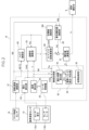
- 2 is a block diagram showing a main configuration of a control unit (ECU) of the internal combustion engine shown in FIG. 1 .
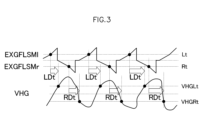
- 3 is a timing chart showing a method for determining a delay time of exhaust gas on a downstream side of a catalytic converter relative to exhaust gas on an upstream side of the catalytic converter in the control device (ECU) of FIG. 2.
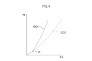
- 4 is a graph showing the relationship between an integrated value X1 of an instantaneous flow rate of exhaust gas in the internal combustion engine of FIG. 1 and an integrated value Y1 of a delay time obtained from the timing diagram of FIG. 3 .
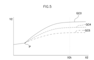
- FIG. 5 is a graph showing the relationship between the total flow rate X2 of exhaust gas from start-up in the internal combustion engine of FIG. 1 and the gradient Y2 of the integrated value Y1 relative to the integrated value X1 in FIG. 4 .
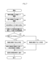
- 3 is a flowchart showing a delay time calculation process performed by a delay time calculation unit of a catalyst treatment unit of a control device (ECU) of FIG. 2 .
- 3 is a flowchart showing an integrated parameter calculation and determination process performed by an integrated parameter calculation and determination unit of a catalyst processing unit of a control device (ECU) of FIG. 2 .
- Figure 1 shows the configuration of the main parts of a four-stroke internal combustion engine according to one embodiment of the present invention.
- the engine body 1 of this internal combustion engine comprises an intake pipe 2 provided in an intake port, and a throttle valve 3 provided in the intake pipe 2 to adjust the amount of intake air supplied to the intake port from an air cleaner 4 according to the opening degree.
- the throttle valve 3 is provided with a throttle sensor 5 that detects the opening of the throttle valve 3.
- a fuel injection valve 6 that injects fuel is provided near the intake port of the intake pipe 2. Fuel is pumped from a fuel tank (not shown) to the fuel injection valve 6 by a fuel pump.
- the intake pipe 2 is provided with an intake pressure sensor 7 that detects the intake pressure in the intake pipe 2, and an intake air temperature sensor 8 that detects the temperature of the intake air in the intake pipe 2.
- an intake pressure sensor 7 that detects the intake pressure in the intake pipe 2
- an intake air temperature sensor 8 that detects the temperature of the intake air in the intake pipe 2.
- a catalytic converter 11 that reduces unburned components in the exhaust of the exhaust pipe 10
- an oxygen concentration sensor 12 that detects the oxygen concentration in the exhaust are provided in the exhaust pipe 10 downstream of the catalytic converter 11 installed in the exhaust pipe 10.
- An ignition plug 13 connected to an ignition device 14 is fixed to the engine body 1.
- an ECU (electronic control unit) 15 issues an ignition timing command to the ignition device 14, a spark discharge occurs in the cylinder combustion chamber of the engine body 1.
- the ECU 15 receives analog voltages indicating the detection values of the throttle sensor 5, intake pressure sensor 7, intake air temperature sensor 8, oxygen concentration sensor 12, cooling water temperature sensor 17, and atmospheric pressure sensor 20 that detects atmospheric pressure.
- the fuel injection valve 6 is also connected to the ECU 15.
- the ECU 15 also receives a signal indicating the rotational angle position of the crankshaft 18 from a crank angle sensor 19. That is, the crank angle sensor 19 magnetically or optically detects multiple protrusions provided at predetermined angles (e.g., 15 degrees) on the outer periphery of a rotor 19a that rotates in conjunction with the crankshaft 18, using a pickup 19b located near the outer periphery of the rotor 19a, and generates a pulse (crank signal) from the pickup 19b every time the crankshaft 18 rotates by the predetermined angle.
- predetermined angles e.g. 15 degrees
- crank angle sensor 19 outputs a signal indicating the reference angle to the ECU 15 each time the piston 9 reaches top dead center or each time the crankshaft 18 rotates 360 degrees.
- Figure 2 shows the main components of the ECU 15.
- the oxygen concentration sensor 12 which supplies the ECU 15 with a detection signal of the oxygen concentration in the exhaust, is provided with a sensor element 12a as a detection unit that is disposed in contact with the exhaust of an internal combustion engine having exhaust pulsation and detects the oxygen concentration in the exhaust, and a sensor heater 12b that is adjacent to the sensor element 12a and heats the sensor element 12a.
- the sensor element 12a has a resistance value that changes in an approximately step-like manner when the exhaust gas from the internal combustion engine has an oxygen concentration close to stoichiometric, and the detection value obtained from the resistance value exhibits a pulse waveform with a peak value according to the temperature of the sensor element 12a and the exhaust pulsation.
- the sensor element 12a is a titania-type sensor element that is a resistive oxygen sensor whose resistance value changes according to the oxygen concentration.
- the ECU 15 includes a heater controller 22 that controls the sensor heater 12b, a temperature calculation unit 23 that calculates a temperature value T that indicates the temperature of the sensor element 12a, and a voltage calculation unit 24 that converts the output signal of the sensor element 12a into a voltage value VHG that is a detection value that indicates the oxygen concentration in the exhaust gas.
- the heater controller 22 controls the temperature of the sensor heater 12b by controlling the amount of current I supplied to the sensor heater 12b from a power source (storage battery) (not shown) using pulse width modulation (PWM) control by the ECU 15.
- the temperature calculation unit 23 calculates the temperature value T by, for example, reading the heater voltage and the amount of current I applied to the sensor heater 12b with the ECU 15 to obtain the resistance value of the sensor heater 12b, and converting the resistance value using table data or a formula that indicates the correspondence between the heater resistance value and the temperature value T, which is prepared in advance in the ECU 15.
- the ECU 15 also includes a rotation speed calculation unit 27 that calculates the rotation speed NE and angular speed NETC of the internal combustion engine based on the detection results of the crank angle sensor 19, an excess ratio calculation unit 25 that calculates an air excess ratio ⁇ based on the temperature value T from the temperature calculation unit 23, the voltage value VHG from the voltage calculation unit 24, and the angular speed NETC from the rotation speed calculation unit 27, and a torque calculation unit 26 that calculates a torque value TQ of the internal combustion engine based on the crank angular speed NETC of the internal combustion engine using, for example, the method described in Japanese Patent Publication No. 06254633.
- the ECU 15 further includes a target value calculation unit 28 that calculates the target excess air ratio ⁇ cmd based on an estimated value of the amount of oxygen stored in the catalyst of the catalytic converter 11, a basic injection amount calculation unit 29 that calculates a basic injection amount BJ based on the rotation speed NE from the rotation speed calculation unit 27 and the pressure PM in the intake pipe 2 from the intake pressure sensor 7, a feedback coefficient calculation unit 30 that determines a feedback coefficient k for correcting the basic fuel injection amount BJ calculated by the basic injection amount calculation unit 29 so that the excess air ratio ⁇ calculated by the excess ratio calculation unit 25 matches the target excess air ratio ⁇ cmd, and an injection amount calculation unit 31 that calculates the fuel injection amount Ti to be supplied for one combustion of the internal combustion engine based on the feedback coefficient k and the basic injection amount BJ, and operates the fuel injection valve 6.
- a target value calculation unit 28 that calculates the target excess air ratio ⁇ cmd based on an estimated value of the amount of oxygen stored in the catalyst of the catalytic converter 11
- PID control is performed based on the deviation between the air excess ratio ⁇ and the target air excess ratio ⁇ cmd, and the feedback coefficient k is calculated.
- the fuel injection valve 6 is opened for a corresponding time.
- the ECU 15 further includes a catalyst processing unit 32 that performs processing corresponding to the inactivation or deterioration of the catalyst of the catalytic converter 11 that purifies the exhaust gas of the internal combustion engine.
- the catalyst processing unit 32 uses a first parameter PM1 and a second parameter PM2 to perform this processing.
- the catalyst processing unit 32 performs the processing corresponding to the inactivation or deterioration based on the ratio of the amount of change in the second parameter PM2 to the amount of change in the first parameter PM1.
- the first parameter is the accumulated value of a parameter corresponding to the torque of the internal combustion engine (e.g., the instantaneous flow rate of exhaust gas flowing into the catalytic converter 11)
- the second parameter PM2 is the accumulated value of a parameter corresponding to the amount of oxygen that the catalytic converter 11 can store from the exhaust gas (e.g., the delay time of the change in the air-fuel ratio of the exhaust gas downstream of the catalytic converter 11 relative to the exhaust gas upstream of the catalytic converter 11).
- the first and second parameters PM1 and PM2 are respectively the accumulated value of the instantaneous exhaust flow rate Em and the accumulated value of the delay time Dt of the change in the air-fuel ratio of the exhaust downstream of the catalytic converter 11 relative to the exhaust upstream of the catalytic converter 11.
- the accumulated exhaust volume EXGFLSM is calculated by resetting the accumulated value to zero each time the exhaust gas flowing into the catalytic converter 11 exceeds the theoretical air-fuel ratio, and accumulating the exhaust gas on the rich side if it exceeds the rich side, and accumulating the exhaust gas on the lean side if it exceeds the lean side.
- the accumulated exhaust volume EXGFLSM when accumulated on the rich side is shown as EXGFLSMr
- EXGFLSMl the accumulated exhaust volume EXGFLSM when accumulated on the lean side
- the voltage value VHG changes with a delay relative to the cumulative exhaust volume EXGFLSM, depending on the health of the catalytic converter 11, by the amount of exhaust passing through the catalytic converter 11. Therefore, based on the ratio of change in the cumulative value of this delay time (second parameter) relative to the cumulative value of the instantaneous flow rate of exhaust flowing into the catalytic converter 11 (first parameter), it is possible to perform processing for the catalytic converter 11 that corresponds to inactivity or deterioration, such as judging the degree of deterioration.
- the delay time Dt at each point in time corresponds to the time RDt from when the accumulated exhaust volume EXGFLSM changes to the rich side and exceeds the rich side threshold value Rt until the voltage value VHG exceeds the rich side threshold value VHGRt, and the time LDt from when the accumulated exhaust volume EXGFLSM changes to the lean side and exceeds the lean side threshold value Lt until the voltage value VHG exceeds the lean side threshold value VHGLt.
- the catalytic processing unit 32 includes a delay time calculation unit 33 that calculates the delay time Dt and instantaneous flow rate Em, an integrated parameter calculation and determination unit 34 that calculates the first and second parameters PM1 and PM2 by integrating the instantaneous flow rate Em and delay time Dt, respectively, and determines whether the catalyst in the catalytic converter 11 is inactive or deteriorated, and a fault diagnosis unit 35 that performs fault diagnosis based on the result of this determination.
- Figure 4 is a graph in which the horizontal axis (x-axis) and vertical axis (y-axis) are the integrated values X1 and Y1 of the instantaneous flow rate Em and delay time Dt calculated by the delay time calculation unit 33.
- the integrated parameter calculation and determination unit 34 determines whether the catalytic converter 11 is inactive or deteriorated based on the ratio of the amount of change in the integrated value Y1 (second parameter PM2) to the amount of change in the integrated value X1 (first parameter PM1), i.e., the slope of the graph curve in Figure 4.
- the graph curve GC3 in FIG. 5 is a graph curve for a new, healthy catalytic converter 11
- the graph curve GC4 is a graph curve that is the threshold (boundary) between a healthy catalytic converter 11 and an unhealthy one
- the graph curve for an unhealthy catalytic converter 11 will be located below the graph curve GC4. Therefore, if a graph curve GC5 (with a small gradient Y2) is obtained for a catalytic converter 11 that is located below the graph curve GC4, then the catalytic converter 11 can be determined to be deteriorated and unhealthy.
- FIG. 6 shows the delay time calculation process by the delay time calculation unit 33. This process is performed at predetermined time intervals.
- the instantaneous flow rate Em of the exhaust gas flowing into the catalytic converter 11 is obtained based on the torque TQ calculated from the crank angular velocity NETC and the temperature value T of the sensor element 12a from the temperature calculation unit 23 (step S1).
- the torque TQ can be calculated, for example, by the method described in Japanese Patent Publication No. 06254633.
- Em The instantaneous flow rate Em is calculated using a simple calculation model according to the following equation (1).
- Em (TQ/MaxTQ) ⁇ (NE/120) ⁇ (TExbd/TSO2) ⁇ Disp ⁇ A (1)
- TQ is the current torque calculated based on the crank angular acceleration NETC mentioned above
- MaxTQ is the maximum torque (constant)
- (TQ/MaxTQ) is the volumetric efficiency
- NE is the rotational speed of the internal combustion engine mentioned above
- (NE/120) is the number of exhausts per second.
- TExbd is the exhaust temperature when the exhaust valve is open (a constant determined in advance taking into account the Carnot cycle)
- TSO2 is the temperature T of the sensor element 12a estimated based on the resistance value of the sensor heater 12b described above
- (TExbd/TSO2) is the calculated value of the expansion rate due to a decrease in exhaust temperature.
- Disp is the displacement of the internal combustion engine (constant).
- A is a coefficient (constant) for adjusting the physical quantity of the exhaust passing volume (liter) and is a coefficient for converting it into an amount per unit time.
- a rich/lean estimated value R is obtained to determine whether the exhaust gas in front of the catalytic converter 11 is rich or lean (step S2).
- the rich/lean estimated value R is obtained by dividing the torque TQ calculated by the torque calculation unit 26 by the injection amount Ti calculated by the injection amount calculation unit 31.
- step S3 it is determined whether the rich/lean estimated value R is smaller than a predetermined value corresponding to the theoretical air-fuel ratio (step S3). If it is determined to be smaller, the exhaust gas in front of the catalytic converter 11 is deemed to be rich, and the inflow exhaust gas amount Er flowing into the catalytic converter 11 is calculated by multiplying the instantaneous flow rate Em by the rich/lean estimated value R. Then, the calculated inflow exhaust gas amount Er is added to the accumulated value up to the previous time to calculate the accumulated flow rate EXGFLSMr (step S4).
- step S7 it is determined whether the voltage value VHG from the voltage calculation unit 24 based on the output signal of the sensor element 12a is equal to or less than the rich side threshold value VHGRt. If it is determined that the voltage value VHG is equal to or less than the threshold value VHGRt, the timer that started timing in step S6 is stopped, and the measured delay time Dt is corrected according to the instantaneous flow rate Em (step S8), the corrected delay time Dtc and the instantaneous flow rate Em are recorded (step S9), and the delay time calculation process is terminated.
- the correction of the delay time Dt according to the instantaneous flow rate Em is performed by obtaining a correction coefficient corresponding to the instantaneous flow rate Em based on a table that associates the instantaneous flow rate Em with a correction coefficient, and multiplying the delay time Dt by the obtained correction coefficient.
- the corrected delay time Dtc corresponds to the delay time RDt in FIG. 3.
- step S3 if it is determined in step S3 that the rich/lean estimated value R is not smaller than the predetermined value corresponding to the theoretical air-fuel ratio, the exhaust gas in front of the catalytic converter 11 is deemed to be lean, and the inflow exhaust gas amount El flowing into the catalytic converter 11 is calculated by multiplying the instantaneous flow rate Em by the rich/lean estimated value R. Then, the calculated inflow exhaust gas amount El is added to the accumulated value up to the previous time to calculate the accumulated flow rate EXGFLSMl (step S10).
- step S11 it is determined whether the integrated value EXGFLSMl is equal to or greater than the lean side threshold value Lt (step S11). If it is determined that it is equal to or greater than the threshold value Lt, a timer that measures the delay time is started (step S12), and the process proceeds to step S13. If it is determined that it is not equal to or greater than the threshold value Lt, the process proceeds directly to step S13.
- step S13 it is determined whether the voltage value VHG from the voltage calculation unit 24 based on the output signal of the sensor element 12a is equal to or greater than the lean side threshold value VHGLt. If it is determined that the voltage value VHG is equal to or greater than the threshold value VHGLt, the timer that started timing in step S12 is stopped and the measured delay time Dt is corrected according to the instantaneous flow rate Em (step S8), the corrected delay time Dtc and the instantaneous flow rate Em are recorded (step S9), and the delay time calculation process is terminated.
- the corrected delay time Dtc corresponds to the delay time LDt in FIG. 3.
- step S13 If it is determined in step S13 that the delay time is not greater than or equal to the threshold value VHGLt, the delay time calculation process ends.
- the gradient Y2 per unit time of the graph curve of the graph shown in FIG. 4, which is configured with the integrated value X1 on the x-axis and the integrated value Y1 on the y-axis, is calculated (step S23).
- This gradient Y2 is the ratio of the increase in the integrated value Y1 to the increase in the integrated value X1 per unit time.
- the instantaneous flow rate Em is added to the total exhaust flow rate X2, which is the integrated value of the instantaneous flow rate from the start of the internal combustion engine, and the gradient Y2 is re-arranged with the total flow rate X2 as the x-axis (step S24).
- step S26 if it is determined that the gradient Y2 is equal to or greater than a predetermined value, it is determined that the catalytic converter 11 is healthy (step S26). In this case, this gradient Y2 is further compared with the gradient Y2 when a new catalytic converter 11 is used, and the degree of deterioration is calculated (step S27). The result is then notified to the fault diagnosis unit 35 (step S28), and the integrated parameter calculation and determination process is terminated.
- the first parameter PM1 is an integrated value of a parameter corresponding to the torque of the internal combustion engine
- the second parameter PM2 is an integrated value of a parameter corresponding to the amount of oxygen that the catalytic converter 11 can store from the exhaust gas.
- the first parameter PM1 is the integrated value of the instantaneous flow rate of exhaust gas flowing into the catalytic converter 11
- the second parameter PM2 is the integrated value of the delay time of the change in the air-fuel ratio of the exhaust gas downstream of the catalytic converter 11 relative to the exhaust gas upstream of the catalytic converter 11. Therefore, when the instantaneous flow rate exceeds the spatial volume of the catalytic converter 11, the reduction in delay time due to the instantaneous flow rate suddenly becomes dominant. Correction of the delay time can be performed by multiplying the correction coefficient that increases as the instantaneous flow rate increases.
- the first parameter may be an integrated value of a parameter corresponding to the torque of the internal combustion engine, and the integrated value of the intake flow rate, the integrated value of the fuel injection amount, or the integrated value of the heat amount applied to the catalyst may be used as the first parameter.
- the second parameter may be an integrated value of a parameter corresponding to the amount of oxygen that the catalytic converter 11 can store from the exhaust gas, so the integrated value of the difference between the peak value or bottom value of the oxygen concentration may be used as the second parameter.
Landscapes
- Chemical & Material Sciences (AREA)
- Engineering & Computer Science (AREA)
- Chemical Kinetics & Catalysis (AREA)
- Health & Medical Sciences (AREA)
- Toxicology (AREA)
- Combustion & Propulsion (AREA)
- Mechanical Engineering (AREA)
- General Engineering & Computer Science (AREA)
- Exhaust Gas After Treatment (AREA)
Abstract
Description
Em=(TQ/MaxTQ)×(NE/120)×(TExbd/TSO2)×Disp×A (1)
Claims (6)
- 内燃機関の排気を浄化する触媒の不活性又は劣化に対応する処理を行う触媒処理部を有する内燃機関の制御装置であって、
前記触媒処理部は、第1パラメータの変化量に対する第2パラメータの変化量の割合に基づいて前記処理を行うように構成され、
前記第1パラメータは、前記内燃機関のトルクに対応するパラメータの積算値であり、
前記第2パラメータは、前記触媒が前記排気から吸蔵可能な酸素の容量に対応するパラメータの積算値であることを特徴とする内燃機関の制御装置。 - 前記内燃機関のトルクに対応するパラメータが大きくなるほど、前記触媒が前記排気から吸蔵可能な酸素の容量に対応するパラメータは大きくなることを特徴とする請求項1に記載の内燃機関の制御装置。
- 前記内燃機関のトルクに対応するパラメータが大きくなるほど、前記触媒が前記排気から吸蔵可能な酸素の容量に対応するパラメータの積算値は大きくなることを特徴とする請求項1に記載の内燃機関の制御装置。
- 前記第1パラメータは、前記触媒に流入する前記排気の瞬時流量の積算値、前記内燃機関における吸気流量の積算値、前記内燃機関における燃料噴射量の積算値、又は前記触媒に付与した熱量の積算値であることを特徴とする請求項1に記載の内燃機関の制御装置。
- 前記第2パラメータは、前記触媒の上流側の前記排気に対する下流側の前記排気の空燃比変化の遅れ時間の積算値、又は前記触媒の上流側の前記排気に対する下流側の前記排気の酸素濃度のピーク値又はボトム値の差の積算値であることを特徴とする請求項1に記載の内燃機関の制御装置。
- 前記第1パラメータは、前記触媒に流入する前記排気の瞬時流量の積算値であり、前記第2パラメータは、前記触媒の上流側の前記排気に対する下流側の前記排気の空燃比変化の遅れ時間の積算値であり、該遅れ時間は、該瞬時流量の増大に応じて増大する補正係数を乗算することにより補正されるものであることを特徴とする請求項1に記載の内燃機関の制御装置。
Priority Applications (2)
| Application Number | Priority Date | Filing Date | Title |
|---|---|---|---|
| PCT/JP2023/025447 WO2025013167A1 (ja) | 2023-07-10 | 2023-07-10 | 内燃機関の制御装置 |
| JP2025532259A JPWO2025013167A1 (ja) | 2023-07-10 | 2023-07-10 |
Applications Claiming Priority (1)
| Application Number | Priority Date | Filing Date | Title |
|---|---|---|---|
| PCT/JP2023/025447 WO2025013167A1 (ja) | 2023-07-10 | 2023-07-10 | 内燃機関の制御装置 |
Publications (1)
| Publication Number | Publication Date |
|---|---|
| WO2025013167A1 true WO2025013167A1 (ja) | 2025-01-16 |
Family
ID=94215247
Family Applications (1)
| Application Number | Title | Priority Date | Filing Date |
|---|---|---|---|
| PCT/JP2023/025447 Ceased WO2025013167A1 (ja) | 2023-07-10 | 2023-07-10 | 内燃機関の制御装置 |
Country Status (2)
| Country | Link |
|---|---|
| JP (1) | JPWO2025013167A1 (ja) |
| WO (1) | WO2025013167A1 (ja) |
Citations (3)
| Publication number | Priority date | Publication date | Assignee | Title |
|---|---|---|---|---|
| JPH08100637A (ja) * | 1994-09-29 | 1996-04-16 | Nippondenso Co Ltd | 排気ガス浄化用触媒劣化検査装置 |
| JP2012211561A (ja) * | 2011-03-31 | 2012-11-01 | Suzuki Motor Corp | 劣化判定装置 |
| JP2013189901A (ja) * | 2012-03-13 | 2013-09-26 | Suzuki Motor Corp | 触媒劣化判定装置 |
-
2023
- 2023-07-10 JP JP2025532259A patent/JPWO2025013167A1/ja active Pending
- 2023-07-10 WO PCT/JP2023/025447 patent/WO2025013167A1/ja not_active Ceased
Patent Citations (3)
| Publication number | Priority date | Publication date | Assignee | Title |
|---|---|---|---|---|
| JPH08100637A (ja) * | 1994-09-29 | 1996-04-16 | Nippondenso Co Ltd | 排気ガス浄化用触媒劣化検査装置 |
| JP2012211561A (ja) * | 2011-03-31 | 2012-11-01 | Suzuki Motor Corp | 劣化判定装置 |
| JP2013189901A (ja) * | 2012-03-13 | 2013-09-26 | Suzuki Motor Corp | 触媒劣化判定装置 |
Also Published As
| Publication number | Publication date |
|---|---|
| JPWO2025013167A1 (ja) | 2025-01-16 |
Similar Documents
| Publication | Publication Date | Title |
|---|---|---|
| US7840334B2 (en) | Engine control system | |
| JP5105006B2 (ja) | 内燃機関の制御装置 | |
| JP2011226328A (ja) | エンジンの空燃比制御装置 | |
| JP2004197716A (ja) | 内燃機関の制御装置 | |
| RU2695236C2 (ru) | Система и способ (варианты) для двигателя | |
| JPH04109045A (ja) | 内燃機関の空燃比制御方法及び装置 | |
| JP4168273B2 (ja) | 内燃機関の制御装置 | |
| JP4370202B2 (ja) | 内燃機関の燃料供給制御装置 | |
| JP2007009807A (ja) | 内燃機関の制御装置 | |
| JP5240094B2 (ja) | 内燃機関の制御装置 | |
| JP4410482B2 (ja) | 二次空気供給装置の異常判定装置 | |
| JP2005351153A (ja) | 触媒劣化判定装置 | |
| WO2025013156A1 (ja) | 内燃機関の制御装置 | |
| JP5726232B2 (ja) | 内燃機関の制御装置及び内燃機関の制御方法 | |
| US20120166064A1 (en) | Intake air flow rate control device for internal combustion engine | |
| JP2004169634A (ja) | 内燃機関の制御装置 | |
| JP5392241B2 (ja) | 多気筒内燃機関 | |
| JP4123100B2 (ja) | 内燃機関の排気浄化装置 | |
| JP4807670B2 (ja) | 制御装置 | |
| JP5067191B2 (ja) | 内燃機関の燃料噴射量制御装置 | |
| JP2016011609A (ja) | 内燃機関の制御装置 | |
| JP2000097014A (ja) | 内燃機関の触媒温度検出装置及び触媒劣化検出装置 | |
| JP4542000B2 (ja) | 内燃機関の可変バルブの制御装置および制御方法 | |
| JP4023174B2 (ja) | 触媒劣化判定装置 | |
| JP6039293B2 (ja) | エンジン制御装置 |
Legal Events
| Date | Code | Title | Description |
|---|---|---|---|
| 121 | Ep: the epo has been informed by wipo that ep was designated in this application |
Ref document number: 23945047 Country of ref document: EP Kind code of ref document: A1 |
|
| ENP | Entry into the national phase |
Ref document number: 2025532259 Country of ref document: JP Kind code of ref document: A |
|
| WWE | Wipo information: entry into national phase |
Ref document number: 2501008841 Country of ref document: TH |
|
| WWE | Wipo information: entry into national phase |
Ref document number: 202647003535 Country of ref document: IN |
|
| NENP | Non-entry into the national phase |
Ref country code: DE |
|
| 122 | Ep: pct application non-entry in european phase |
Ref document number: 23945047 Country of ref document: EP Kind code of ref document: A1 |