WO2025009142A1 - スクロール式流体機械のメンテナンス方法及びスクロール式流体機械 - Google Patents
スクロール式流体機械のメンテナンス方法及びスクロール式流体機械 Download PDFInfo
- Publication number
- WO2025009142A1 WO2025009142A1 PCT/JP2023/025061 JP2023025061W WO2025009142A1 WO 2025009142 A1 WO2025009142 A1 WO 2025009142A1 JP 2023025061 W JP2023025061 W JP 2023025061W WO 2025009142 A1 WO2025009142 A1 WO 2025009142A1
- Authority
- WO
- WIPO (PCT)
- Prior art keywords
- scroll
- fitting surface
- fluid machine
- unit
- type fluid
- Prior art date
- Legal status (The legal status is an assumption and is not a legal conclusion. Google has not performed a legal analysis and makes no representation as to the accuracy of the status listed.)
- Ceased
Links
Images





Classifications
-
- F—MECHANICAL ENGINEERING; LIGHTING; HEATING; WEAPONS; BLASTING
- F04—POSITIVE - DISPLACEMENT MACHINES FOR LIQUIDS; PUMPS FOR LIQUIDS OR ELASTIC FLUIDS
- F04C—ROTARY-PISTON, OR OSCILLATING-PISTON, POSITIVE-DISPLACEMENT MACHINES FOR LIQUIDS; ROTARY-PISTON, OR OSCILLATING-PISTON, POSITIVE-DISPLACEMENT PUMPS
- F04C18/00—Rotary-piston pumps specially adapted for elastic fluids
- F04C18/02—Rotary-piston pumps specially adapted for elastic fluids of arcuate-engagement type, i.e. with circular translatory movement of co-operating members, each member having the same number of teeth or tooth-equivalents
Definitions
- the present invention relates to a maintenance method for a scroll type fluid machine and a scroll type fluid machine.
- Patent Document 1 discloses a scroll-type fluid machine.
- the scroll-type fluid machine includes a main unit and a motor unit that are connected to each other.
- the main unit includes a fixed scroll, an orbiting scroll that forms a working chamber between the fixed scroll and the orbiting scroll, a support that supports the orbiting scroll so that it can orbit, and a casing that is connected to the fixed scroll and that houses the orbiting scroll and the support.
- the motor unit orbits the orbiting scroll via a crankshaft.
- the flange of the motor unit has a protruding portion that protrudes toward the main unit, and this protruding portion has a mating surface on the outer periphery.
- the housing of the main unit has a mating surface on the inner periphery.
- the mating surface of the protruding part of the flange of the motor unit and the mating surface of the housing of the main unit can become worn due to factors such as micro-vibrations while the compressor is operating. If wear occurs, the accuracy of aligning the center of the motor unit with the center of the main unit will decrease when replacing the main unit. This makes it necessary to replace not only the main unit but also the flange of the motor unit.
- the present invention was made in consideration of the above, and one of its objectives is to eliminate the need to replace the motor unit flange when replacing the main unit.
- the present invention includes a plurality of means for solving the above problem, and one example thereof is a maintenance method for replacing a main body unit of a scroll-type fluid machine including a fixed scroll, an orbiting scroll that forms an operating chamber between the fixed scroll, a support that orbitally supports the orbiting scroll, and a main body casing that is connected to the fixed scroll and that houses the orbiting scroll and the support, and a motor unit that is connected to the main body unit and orbits the orbiting scroll via a crankshaft, the flange of the motor unit has a protruding portion that protrudes toward the main body unit and has a first fitting surface and a second fitting surface on the outer periphery that are located at different positions in the circumferential direction or radial direction, the main body casing of the main body unit before replacement has a third fitting surface on the inner periphery that fits only with the first fitting surface, and the main body casing of the main body unit after replacement has a fourth
- FIG. 1 is a perspective view illustrating a structure of a scroll compressor according to a first embodiment of the present invention.
- 1 is a perspective view illustrating a structure of a scroll compressor according to a first embodiment of the present invention.
- 1 is a perspective view illustrating a structure of a scroll compressor according to a first embodiment of the present invention.
- 1 is an axial cross-sectional view illustrating a structure of a scroll compressor according to a first embodiment of the present invention.
- 4 is an axial cross-sectional view illustrating removal of a first main unit from a motor unit in the first embodiment of the present invention.
- FIG. 4 is an axial cross-sectional view showing the attachment of a second main unit to a motor unit in the first embodiment of the present invention.
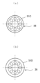
- FIG. 7 is a radial cross-sectional view taken along line AA of FIG. 5 or FIG. 6. 5 and a radial cross-sectional view taken along line CC of FIG. 6.
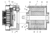
- FIG. 10 is an axial cross-sectional view illustrating removal of a third main body unit from a motor unit in a second embodiment of the present invention.
- FIG. 11 is an axial cross-sectional view showing attachment of a fourth main body unit to a motor unit in a second embodiment of the present invention.
- 11 is a radial cross-sectional view taken along line DD of FIG. 9 or line EE of FIG. 10 .
- 11 is a radial cross-sectional view taken along line FF in FIG. 9 and line GG in FIG. 10 .
- FIGS. 1 and 2 are perspective views (as viewed from the main unit side) showing the structure of the scroll compressor in this embodiment
- FIG. 3 is a perspective view (as viewed from the motor unit side) showing the structure of the scroll compressor in this embodiment
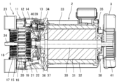
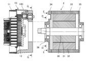
- FIG. 4 is an axial cross-sectional view showing the structure of the scroll compressor in this embodiment.
- FIGS. 1 and 4 show the main unit, motor unit, and duct connected.
- FIGS. 2 and 3 show the main unit and motor unit separated, and the duct is omitted.
- the main casing of the main unit is shown as not having the features of this embodiment (see FIGS. 5 and 8(a) or 6 and 8(b) described below).
- the scroll compressor of this embodiment comprises a main unit 1, a motor unit 2, and a duct 3, which are connected to each other.
- the duct 3 directs cooling air generated by a cooling fan (described in detail later) of the motor unit 2 to the main unit 1.
- the main unit 1 includes a fixed scroll 11, a rotating scroll 12 that forms a compression chamber (working chamber) between the fixed scroll 11 and the rotating scroll 12, a support 13 that supports the rotating scroll 12 so that it can rotate, and a cylindrical main casing 14 that is connected to the fixed scroll 11 and houses the rotating scroll 12 and the support 13.
- the fixed scroll 11 has a substantially circular mirror plate 15, a spiral wrap 16 standing on one side of the mirror plate 15 (right side in Fig. 4), a number of cooling fins 17 standing on the opposite side of the mirror plate 15 (left side in Fig. 4), and a cover 18 attached to the tip side of the cooling fins 17 (left side in Fig. 4). Cooling air from the duct 3 flows through the cooling flow path formed by the cooling fins 17 and the cover 18. This cools the fixed scroll 11.
- the orbiting scroll 12 comprises a substantially circular mirror plate 19, a spiral wrap 20 erected on one side of the mirror plate 19 (left side in FIG. 4), a number of cooling fins 21 erected on the opposite side of the mirror plate 19 (right side in FIG. 4), and a plate 22 attached to the tip side of the cooling fins 21 (right side in FIG. 4). Cooling air from the duct 3 flows through the cooling flow path formed by the cooling fins 21 and the plate 22. This cools the orbiting scroll 12.
- the support 13 is composed of, for example, three auxiliary crankshafts and three pairs of auxiliary bearings that support the auxiliary crankshafts.
- the support 13 may be composed of a ball joint, an Oldham joint, or the like.
- the support 13 supports the orbiting scroll 12 so that it can rotate, and prevents the orbiting scroll 12 from rotating on its own axis.
- the support 13 also bears the axial load of the orbiting scroll 12.
- the motor unit 2 orbits the orbiting scroll 12 via the crankshaft 30.
- a number of working chambers are formed between the wrap 16 of the fixed scroll 11 and the wrap 20 of the orbiting scroll 12.
- each working chamber moves from the outside to the inside in the wrap extension direction (in other words, closer to the radial center of the fixed scroll 11) and sequentially performs an intake process, a compression process, and a discharge process.
- the working chamber in the intake process draws in gas (e.g., air) through the intake filter 23 and the intake passage of the fixed scroll 11.
- the working chamber in the compression process compresses the gas (in other words, changes the pressure of the gas).
- the working chamber in the discharge process discharges the compressed gas (in other words, gas whose pressure has been changed) through the discharge passage 24 of the fixed scroll 11.
- the motor unit 2 comprises the crankshaft 30 described above, a rotor 31 fixed to the outer periphery of the crankshaft 30, a stator 32 arranged at a distance from the outer periphery of the rotor 31, a cylindrical motor casing 33 supporting the stator 32, a flange 34 attached to one axial side of the motor casing 33 (left side in FIG. 4), and an end bracket 35 attached to the opposite axial side of the motor casing 33 (right side in FIG. 4).
- the flange 34 of the motor unit 2 has a protruding portion 36 that protrudes toward the main unit 1 (left side in FIG. 4).
- the flange 34 of the motor unit 2 is connected to the main unit casing 14 of the main unit 1 by a number of bolts 4 with the protruding portion 36 housed in the main unit casing 14 of the main unit 1.
- the crankshaft 30 is rotatably supported by a main bearing 37 (load side bearing) provided on the flange 34 and a secondary bearing 38 (non-load side bearing) provided on the end bracket 35.
- the crankshaft 30 rotates due to the electromagnetic force generated by the rotor 31 and the stator 32.
- crankshaft 30 protrudes from the flange 34 and is provided with a crank portion 39.
- the crank portion 39 of the crankshaft 30 is eccentric from the center of the crankshaft 30 and is connected to the boss portion of the plate 22 of the orbiting scroll 12 via an orbiting bearing 40. Note that the orbiting scroll 12 does not need to be provided with the plate 22. In this case, the crank portion 39 of the crankshaft 30 may be connected to the boss portion of the end plate 19 of the orbiting scroll 12 via the orbiting bearing 40.
- the orbiting bearing 40 is configured to be separable into an outer ring fixed to the boss portion of the orbiting scroll 12 and an inner ring fixed to the crank portion 39 of the crankshaft 30. This allows the main unit 1 and the motor unit 2 to be separated.
- the other end of the crankshaft 30 protrudes from the end bracket 35 and is provided with a cooling fan 41.
- the cooling fan 41 rotates together with the crankshaft 30 to generate cooling air.
- the duct 3 directs the cooling air generated by the cooling fan 41 to the cooling flow path of the main unit 1.
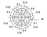
- FIG. 5 is a radial cross-sectional view taken along the line A-A in FIG. 5 or FIG. 6,
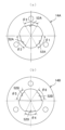
- FIG. 8(a) is a radial cross-sectional view taken along the line B-B in FIG. 5
- FIG. 8(b) is a radial cross-sectional view taken along the line C-C in FIG. 6.
- part of the main unit 1A or 1B and part of the motor unit 2 are omitted from illustration in FIG. 5 and FIG. 6.
- the support body 13 is omitted from illustration in FIG. 8(a) and FIG. 8(b).
- the protrusion 36 of the flange 34 of the motor unit 2 has an outer peripheral mating surface 51A (first mating surface) and a mating surface 51B (second mating surface) that are located at different radial positions.
- first mating surface first mating surface
- second mating surface second mating surface
- three mating surfaces 51B which are formed in circumferential ranges ⁇ 4, ⁇ 5, and ⁇ 6 (for example, ranges of 65 degrees to 115 degrees, 185 degrees to 235 degrees, and 305 degrees to 355 degrees).
- the main body casing 14A of the main unit 1A has an inner mating surface 52A (third mating surface) that only matings with the above-mentioned mating surface 51A.
- the main body casing 14A has a recess recessed radially outward between the mating surfaces 52A, forming a gap with the above-mentioned mating surface 51B.
- the fitting surface 51A of the protrusion 36 of the flange 34 of the motor unit 2 fits with the fitting surface 52A of the main casing 14A of the main unit 1A (so-called spigot structure), improving the accuracy of alignment between the center of the motor unit 2 (specifically, the center of the crankshaft 30) and the center of the main unit 1A (specifically, the orbital center of the orbiting scroll 12).
- the main body casing 14B of the main unit 1B has an inner mating surface 52B (fourth mating surface) that only matings with the above-mentioned mating surface 51B.
- the main body casing 14B has a recess recessed radially outward between the mating surfaces 52B, forming a gap between the mating surfaces 51A.
- the circumferential range of mating surface 51A corresponding to mating surface 52A and the circumferential range of mating surface 51B corresponding to mating surface 52B are separated by a predetermined distance (e.g., 5 degrees). This further prevents wear on mating surface 51B before replacing the main unit.
- Fig. 11(a) is a radial cross-sectional view taken along the line D-D in Fig. 9 or Fig. 10
- Fig. 11(b) is a radial cross-sectional view taken along the line E-E in Fig. 9 or Fig. 10.
- Fig. 12(a) is a radial cross-sectional view taken along the line F-F in Fig. 9, and Fig. 12(b) is a radial cross-sectional view taken along the line G-G in Fig. 10.
- the main body casing 14D of the main unit 1D has an inner mating surface 52D (fourth mating surface) that only fits into the above-mentioned mating surface 51D.
- the main body casing 14D forms a gap with the above-mentioned mating surface 51C.
- the precision of the alignment between the center of the motor unit 2 and the center of the main unit 1B is improved by the engagement of the mating surface 51D of the protruding portion 36 of the flange 34 of the motor unit 2 with the mating surface 52D of the main casing 14D of the main unit 1D.
Landscapes
- Engineering & Computer Science (AREA)
- Mechanical Engineering (AREA)
- General Engineering & Computer Science (AREA)
- Rotary Pumps (AREA)
Abstract
本体ユニットを交換する際にモータユニットの一部の交換を不要にするスクロール式流体機械のメンテナンス方法及びスクロール式流体機械を提供することにある。 本体ユニット1Aとモータユニット2とを備えたスクロール式圧縮機に対し、本体ユニット1Aを本体ユニット1Bに交換するメンテナンス方法において、モータユニット2のフランジ34の突出部36は、周方向の位置が互いに異なる外周側の嵌合面51A及び嵌合面51Bを有し、本体ユニット1Aの本体ケーシング14Aは、嵌合面51Aのみに嵌合する内周側の嵌合面52Aを有し、本体ユニット1Bの本体ケーシング14Bは、嵌合面51Bのみに嵌合する内周側の嵌合面52Bを有する。
Description
本発明は、スクロール式流体機械のメンテナンス方法及びスクロール式流体機械に関する。
特許文献1は、スクロール式流体機械を開示する。スクロール式流体機械は、互いに連結された本体ユニット及びモータユニットを備える。本体ユニットは、固定スクロールと、固定スクロールとの間で作動室を形成する旋回スクロールと、旋回スクロールを旋回可能に支持する支持体と、固定スクロールに連結されて旋回スクロール及び支持体を収容するケーシングとを備える。モータユニットは、クランク軸を介し旋回スクロールを旋回させる。
特許文献1で図示されているように、モータユニットのフランジは、本体ユニット側に突出する突出部を有し、この突出部は、外周側の嵌合面を有する。本体ユニットのハウジングは、内周側の嵌合面を有する。モータユニットと本体ユニットを連結する際、モータユニットのフランジの突出部の嵌合面と本体ユニットのハウジングの嵌合面との嵌合(いわゆるインロー構造)により、モータユニットの中心(詳細には、クランク軸の中心)と本体ユニットの中心(詳細には、旋回スクロールの旋回中心)との位置合わせの精度を高める。
しかし、モータユニットのフランジの突出部の嵌合面と本体ユニットのハウジングの嵌合面は、圧縮機運転中の微振動等の要因によって摩耗する可能性がある。摩耗が発生すれば、本体ユニットを交換する際に、モータユニットの中心と本体ユニットの中心との位置合わせの精度が低下する。そのため、本体ユニットだけでなく、モータユニットのフランジも交換する必要が生じる。
本発明は、上記事柄に鑑みてなされたものであり、本体ユニットを交換する際にモータユニットのフランジの交換を不要にすることを課題の一つとする。
上記課題を解決するために、請求の範囲に記載の構成を適用する。本発明は、上記課題を解決するための手段を複数含んでいるが、その一例を挙げるならば、固定スクロール、前記固定スクロールとの間で作動室を形成する旋回スクロール、前記旋回スクロールを旋回可能に支持する支持体、並びに前記固定スクロールに連結されて前記旋回スクロール及び前記支持体を収容する本体ケーシングを備えた本体ユニットと、前記本体ユニットに連結され、クランク軸を介し前記旋回スクロールを旋回させるモータユニットとを備えたスクロール式流体機械に対し、前記本体ユニットを交換するメンテナンス方法において、前記モータユニットのフランジは、前記本体ユニット側に突出すると共に、周方向又は径方向の位置が互いに異なる外周側の第1嵌合面及び第2嵌合面を有する突出部を有し、交換前の前記本体ユニットの前記本体ケーシングは、前記第1嵌合面のみに嵌合する内周側の第3嵌合面を有し、交換後の前記本体ユニットの前記本体ケーシングは、前記第2嵌合面のみに嵌合する内周側の第4嵌合面を有する。
本発明によれば、本体ユニットを交換する際にモータユニットのフランジの交換を不要にすることができる。
なお、上記以外の課題、構成及び効果は、以下の説明により明らかにされる。
本発明の適用対象としてスクロール式圧縮機を例にとり、図面を参照しつつ、本発明の第1の実施形態を説明する。
図1及び図2は、本実施形態におけるスクロール式圧縮機の構造を表す斜視図(本体ユニット側から見た斜視図)であり、図3は、本実施形態におけるスクロール式圧縮機の構造を表す斜視図(モータユニット側から見た斜視図)である。図4は、本実施形態におけるスクロール式圧縮機の構造を表す軸方向断面図である。なお、図1及び図4は、本体ユニット、モータユニット、及びダクトを連結した状態を示す。図2及び図3は、本体ユニットとモータユニットを分離した状態を示し、ダクトの図示を省略している。図3及び図4において、便宜上、本体ユニットの本体ケーシングは、本実施形態の特徴(後述する図5及び図8(a)又は図6及び図8(b)参照)を有しないものとして示す。
本実施形態のスクロール式圧縮機は、互いに連結された本体ユニット1、モータユニット2、及びダクト3を備える。ダクト3は、モータユニット2の冷却ファン(詳細は後述)で生起された冷却風を、本体ユニット1へ導出する。
本体ユニット1は、固定スクロール11と、固定スクロール11との間で圧縮室(作動室)を形成する旋回スクロール12と、旋回スクロール12を旋回可能に支持する支持体13と、固定スクロール11に連結されて旋回スクロール12及び支持体13を収容する筒状の本体ケーシング14とを備える。
固定スクロール11は、略円形状の鏡板15と、鏡板15の一面側(図4の右側)に立設された渦巻き状のラップ16と、鏡板15の反対面側(図4の左側)に立設された複数の冷却フィン17と、冷却フィン17の先端側(図4の左側)に取付けられたカバー18とを有する。冷却フィン17及びカバー18で形成された冷却流路にダクト3からの冷却風が流れる。これにより、固定スクロール11が冷却される。
旋回スクロール12は、略円形状の鏡板19と、鏡板19の一面側(図4の左側)に立設された渦巻き状のラップ20と、鏡板19の反対面側(図4の右側)に立設された複数の冷却フィン21と、冷却フィン21の先端側(図4の右側)に取付けられたプレート22とを備える。冷却フィン21及びプレート22で形成された冷却流路にダクト3からの冷却風が流れる。これにより、旋回スクロール12が冷却される。
支持体13は、例えば、3つの補助クランク軸と、補助クラン軸を支持する3対の補助軸受とで構成されている。支持体13は、ボール継手又はオルダム継手等を用いて構成されてもよい。支持体13は、旋回スクロール12を旋回可能に支持すると共に、旋回スクロール12の自転を防止する。また、支持体13は、旋回スクロール12の軸方向荷重を受ける。
モータユニット2は、クランク軸30を介し旋回スクロール12を旋回させる。固定スクロール11のラップ16と旋回スクロール12のラップ20の間には、複数の作動室が形成されている。各作動室は、旋回スクロール12の旋回に伴い、ラップ延在方向の外側から内側に向かって(言い換えれば、固定スクロール11の径方向中心部に近づくように)移動すると共に、吸入過程、圧縮過程、及び吐出過程を順次行う。吸入過程の作動室は、吸入フィルタ23及び固定スクロール11の吸入流路を介し気体(例えば空気)を吸入する。圧縮過程の作動室は、気体を圧縮する(言い換えれば、気体の圧力を変化させる)。吐出過程の作動室は、固定スクロール11の吐出流路24を介し圧縮気体(言い換えれば、圧力が変化された気体)を吐出する。
モータユニット2は、上述したクランク軸30と、クランク軸30の外周側に固定された回転子31と、回転子31の外周側に離間して配置された固定子32と、固定子32を支持する筒状のモータケーシング33と、モータケーシング33の軸方向一方側(図4の左側)に取付けられたフランジ34と、モータケーシング33の軸方向反対側(図4の右側)に取付けられたエンドブラケット35とを備える。
モータユニット2のフランジ34は、本体ユニット1側(図4の左側)に突出した突出部36を有する。モータユニット2のフランジ34は、突出部36が本体ユニット1の本体ケーシング14に収容された状態で、複数のボルト4により、本体ユニット1の本体ケーシング14に連結される。
クランク軸30は、フランジ34に設けられた主軸受37(負荷側軸受)と、エンドブラケット35に設けられた副軸受38(反負荷側軸受)とで回転可能に支持されている。クランク軸30は、回転子31及び固定子32によって生じる電磁力により、回転する。
クランク軸30の一端側(図4の左側)は、フランジ34より突出しており、クランク部39が設けられている。クランク軸30のクランク部39は、クランク軸30の中心から偏心しており、旋回軸受40を介し旋回スクロール12のプレート22のボス部に接続される。なお、旋回スクロール12は、プレート22を備えなくてもよい。この場合、クランク軸30のクランク部39は、旋回軸受40を介し旋回スクロール12の鏡板19のボス部に接続されればよい。
旋回軸受40は、旋回スクロール12のボス部に固定された外輪と、クランク軸30のクランク部39に固定された内輪とに分離可能に構成されている。これにより、本体ユニット1とモータユニット2が分離可能である。
クランク軸30の他端側(図4の右側)は、エンドブラケット35より突出しており、冷却ファン41が設けられている。冷却ファン41は、クランク軸30と共に回転して冷却風を生起する。ダクト3は、冷却ファン41で生起された冷却風を本体ユニット1の冷却流路へ導出する。
次に、上述したスクロール式圧縮機のメンテナンスとして、本体ユニットの交換について説明する。
本実施形態では、図5で示すように、モータユニット2から本体ユニット1Aを取外し、その後、図6で示すように、モータユニット2へ本体ユニット1Bを取付ける。図7は、図5又は図6の矢視A-Aによる径方向断面図であり、図8(a)は、図5の矢視B-Bによる径方向断面図であり、図8(b)は、図6の矢視C-Cによる径方向断面図である。なお、図5及び図6においては、便宜上、本体ユニット1A又は1Bの一部及びモータユニット2の一部の図示を省略している。また、図8(a)及び図8(b)においては、便宜上、支持体13の図示を省略している。
モータユニット2のフランジ34の突出部36は、径方向の位置が互いに異なる外周側の嵌合面51A(第1嵌合面)及び嵌合面51B(第2嵌合面)を有する。嵌合面51Aは、例えば、3つあって、周方向範囲θ1,θ2,θ3(例えば0度~60度の範囲、120度~180度の範囲、240度~300度の範囲)に形成されている。嵌合面51Bは、例えば、3つあって、周方向範囲θ4,θ5,θ6(例えば65度~115度の範囲、185度~235度の範囲、305度~355度の範囲)に形成されている。
本体ユニット1Aの本体ケーシング14Aは、上述した嵌合面51Aのみに嵌合する内周側の嵌合面52A(第3嵌合面)を有する。本体ケーシング14Aの嵌合面52Aは、嵌合面51Aと同様、3つあって、周方向範囲θ1,θ2,θ3に形成されている。本体ケーシング14Aは、嵌合面52Aの間にて径方向外側に窪んだ窪みを有し、上述した嵌合面51Bとの間で隙間を形成する。
モータユニット2と本体ユニット1Aを連結する際、モータユニット2のフランジ34の突出部36の嵌合面51Aと本体ユニット1Aの本体ケーシング14Aの嵌合面52Aとの嵌合(いわゆるインロー構造)により、モータユニット2の中心(詳細には、クランク軸30の中心)と本体ユニット1Aの中心(詳細には、旋回スクロール12の旋回中心)との位置合わせの精度を高める。その後、圧縮機運転中の微振動等の要因により、モータユニット2のフランジ34の突出部36の嵌合面51Aと本体ユニット1Aの本体ケーシング14Aの嵌合面52Aに摩耗が生じたとしても、モータユニット2のフランジ34の突出部36の嵌合面51Bに摩耗が生じない。
本体ユニット1Bの本体ケーシング14Bは、上述した嵌合面51Bのみに嵌合する内周側の嵌合面52B(第4嵌合面)を有する。本体ケーシング14Bの嵌合面52Bは、嵌合面51Bと同様、3つあって、周方向範囲θ4,θ5,θ6に形成されている(すなわち、嵌合面52Aとは周方向の位置が異なる)。本体ケーシング14Bは、嵌合面52Bの間にて径方向外側に窪んだ窪みを有し、上述した嵌合面51Aとの間で隙間を形成する。
モータユニット2と本体ユニット1Aを分離し、モータユニット2と本体ユニット1Bを連結する際、モータユニット2のフランジ34の突出部36の嵌合面51Bと本体ユニット1Bの本体ケーシング14Bの嵌合面52Bとの嵌合により、モータユニット2の中心と本体ユニット1Bの中心との位置合わせの精度を高める。ここで、上述したようにモータユニット2のフランジ34の突出部36の嵌合面51Bは摩耗が生じていない。そのため、モータユニット2のフランジ34の交換を不要にすることができる。
また、本実施形態では、嵌合面52Aに対応する嵌合面51Aの周方向範囲と嵌合面52Bに対応する嵌合面51Bの周方向範囲は、所定の間隔(例えば5度)で離されている。そのため、本体ユニットの交換前、嵌合面51Bに摩耗が生じるのを更に防止することができる。
なお、第1の実施形態において、嵌合面51A,51B,52A,52Bは、それぞれ3つある場合を例にとって説明したが、これに限られず、それぞれ4つ以上あってもよい。
本発明の第2の実施形態を説明する。なお、本実施形態において、第1の実施形態と同等の部分は同一の符号を付し、適宜、説明を省略する。
本実施形態では、図9で示すように、モータユニット2から本体ユニット1Cを取外し、その後、図10で示すように、モータユニット2へ本体ユニット1Dを取付ける。図11(a)は、図9又は図10の矢視D-Dによる径方向断面図であり、図11(b)は、図9又は図10の矢視E-Eによる径方向断面図である。図12(a)は、図9の矢視F-Fによる径方向断面図であり、図12(b)は、図10の矢視G-Gによる径方向断面図である。
モータユニット2のフランジ34の突出部36は、軸方向及び径方向の位置が互いに異なる外周側の嵌合面51C(第1嵌合面)及び嵌合面51D(第2嵌合面)を有する。嵌合面51Cは、嵌合面51Dより、本体ユニット側かつクランク軸の中心側に位置する。
本体ユニット1Cの本体ケーシング14Cは、上述した嵌合面51Cのみに嵌合する内周側の嵌合面52C(第3嵌合面)を有する。本体ケーシング14Cは、上述した嵌合面51Dとの間で隙間を形成する。
モータユニット2と本体ユニット1Cを連結する際、モータユニット2のフランジ34の突出部36の嵌合面51Cと本体ユニット1Cの本体ケーシング14Cの嵌合面52Cとの嵌合により、モータユニット2の中心と本体ユニット1Cの中心との位置合わせの精度を高める。その後、圧縮機運転中の微振動等の要因により、モータユニット2のフランジ34の突出部36の嵌合面51Cと本体ユニット1Cの本体ケーシング14Cの嵌合面52Cに摩耗が生じたとしても、モータユニット2のフランジ34の突出部36の嵌合面51Dに摩耗が生じない。
本体ユニット1Dの本体ケーシング14Dは、上述した嵌合面51Dのみに嵌合する内周側の嵌合面52D(第4嵌合面)を有する。本体ケーシング14Dは、上述した嵌合面51Cとの間で隙間を形成する。
モータユニット2と本体ユニット1Cを分離し、モータユニット2と本体ユニット1Dを連結する際、モータユニット2のフランジ34の突出部36の嵌合面51Dと本体ユニット1Dの本体ケーシング14Dの嵌合面52Dとの嵌合により、モータユニット2の中心と本体ユニット1Bの中心との位置合わせの精度を高める。ここで、上述したようにモータユニット2のフランジ34の突出部36の嵌合面51Dは摩耗が生じていない。そのため、モータユニット2のフランジ34の交換を不要にすることができる。
なお、以上においては、本発明の適用対象としてスクロール式圧縮機を例にとって説明したが、これに限られない。例えばスクロール式真空ポンプ等に本発明を適用してもよい。
1,1A,1B,1C,1D…本体ユニット、2…モータユニット、11…固定スクロール、12…旋回スクロール、13…支持体、14,14A,14B,14C,14D…本体ケーシング、30…クランク軸、34…フランジ、36…突出部、51A,51C…嵌合面(第1嵌合面)、51B,51D…(第2嵌合面)、52A,52C…嵌合面(第3嵌合面)、52B,52D…嵌合面(第4嵌合面)
Claims (6)
- 固定スクロール、前記固定スクロールとの間で作動室を形成する旋回スクロール、前記旋回スクロールを旋回可能に支持する支持体、並びに前記固定スクロールに連結されて前記旋回スクロール及び前記支持体を収容する本体ケーシングを備えた本体ユニットと、前記本体ユニットに連結され、クランク軸を介し前記旋回スクロールを旋回させるモータユニットとを備えたスクロール式流体機械に対し、前記本体ユニットを交換するメンテナンス方法において、
前記モータユニットのフランジは、前記本体ユニット側に突出すると共に、周方向又は径方向の位置が互いに異なる外周側の第1嵌合面及び第2嵌合面を有する突出部を有し、
交換前の前記本体ユニットの前記本体ケーシングは、前記第1嵌合面のみに嵌合する内周側の第3嵌合面を有し、
交換後の前記本体ユニットの前記本体ケーシングは、前記第2嵌合面のみに嵌合する内周側の第4嵌合面を有することを特徴とするスクロール式流体機械のメンテナンス方法。 - 請求項1に記載のスクロール式流体機械のメンテナンス方法において、
前記第1嵌合面及び前記第2嵌合面は、周方向の位置が互いに異なると共に、それぞれ3つ以上あり、
前記第3嵌合面及び前記第4嵌合面は、周方向の位置が互いに異なると共に、それぞれ3つ以上あることを特徴とするスクロール式流体機械のメンテナンス方法。 - 請求項2に記載のスクロール式流体機械のメンテナンス方法において、
前記第3嵌合面に対応する前記第1嵌合面の周方向範囲と前記第4嵌合面に対応する前記第2嵌合面の周方向範囲が所定の間隔で離されていることを特徴とするスクロール式流体機械のメンテナンス方法。 - 固定スクロール、前記固定スクロールとの間で作動室を形成する旋回スクロール、前記旋回スクロールを旋回可能に支持する支持体、並びに前記固定スクロールに連結されて前記旋回スクロール及び前記支持体を収容する本体ケーシングを備えた本体ユニットと、前記本体ユニットに連結され、クランク軸を介し前記旋回スクロールを旋回させるモータユニットとを備えたスクロール式流体機械において、
前記モータユニットのフランジは、前記本体ユニット側に突出すると共に、周方向又は径方向の位置が互いに異なる外周側の第1嵌合面及び第2嵌合面を有する突出部を有し、
前記本体ユニットの前記本体ケーシングは、前記第1嵌合面のみに嵌合する内周側の第3嵌合面と前記第2嵌合面のみに嵌合する内周側の第4嵌合面とのうちの一方を選択的に有することを特徴とするスクロール式流体機械。 - 請求項4に記載のスクロール式流体機械において、
前記第1嵌合面及び前記第2嵌合面は、周方向の位置が互いに異なると共に、それぞれ3つ以上あり、
前記第3嵌合面及び前記第4嵌合面は、周方向の位置が互いに異なると共に、それぞれ3つ以上あることを特徴とするスクロール式流体機械。 - 請求項5に記載のスクロール式流体機械において、
前記第3嵌合面に対応する前記第1嵌合面の周方向範囲と前記第4嵌合面に対応する前記第2嵌合面の周方向範囲が所定の間隔で離されていることを特徴とするスクロール式流体機械。
Priority Applications (3)
| Application Number | Priority Date | Filing Date | Title |
|---|---|---|---|
| PCT/JP2023/025061 WO2025009142A1 (ja) | 2023-07-06 | 2023-07-06 | スクロール式流体機械のメンテナンス方法及びスクロール式流体機械 |
| CN202380095681.1A CN120958238A (zh) | 2023-07-06 | 2023-07-06 | 涡旋式流体机械的维护方法和涡旋式流体机械 |
| JP2025530922A JPWO2025009142A1 (ja) | 2023-07-06 | 2023-07-06 |
Applications Claiming Priority (1)
| Application Number | Priority Date | Filing Date | Title |
|---|---|---|---|
| PCT/JP2023/025061 WO2025009142A1 (ja) | 2023-07-06 | 2023-07-06 | スクロール式流体機械のメンテナンス方法及びスクロール式流体機械 |
Publications (1)
| Publication Number | Publication Date |
|---|---|
| WO2025009142A1 true WO2025009142A1 (ja) | 2025-01-09 |
Family
ID=94171697
Family Applications (1)
| Application Number | Title | Priority Date | Filing Date |
|---|---|---|---|
| PCT/JP2023/025061 Ceased WO2025009142A1 (ja) | 2023-07-06 | 2023-07-06 | スクロール式流体機械のメンテナンス方法及びスクロール式流体機械 |
Country Status (3)
| Country | Link |
|---|---|
| JP (1) | JPWO2025009142A1 (ja) |
| CN (1) | CN120958238A (ja) |
| WO (1) | WO2025009142A1 (ja) |
Citations (2)
| Publication number | Priority date | Publication date | Assignee | Title |
|---|---|---|---|---|
| JP2006029238A (ja) * | 2004-07-16 | 2006-02-02 | Anest Iwata Corp | 回転機械 |
| WO2018020651A1 (ja) * | 2016-07-29 | 2018-02-01 | 株式会社日立産機システム | スクロール式流体機械及びその組立方法 |
-
2023
- 2023-07-06 CN CN202380095681.1A patent/CN120958238A/zh active Pending
- 2023-07-06 WO PCT/JP2023/025061 patent/WO2025009142A1/ja not_active Ceased
- 2023-07-06 JP JP2025530922A patent/JPWO2025009142A1/ja active Pending
Patent Citations (2)
| Publication number | Priority date | Publication date | Assignee | Title |
|---|---|---|---|---|
| JP2006029238A (ja) * | 2004-07-16 | 2006-02-02 | Anest Iwata Corp | 回転機械 |
| WO2018020651A1 (ja) * | 2016-07-29 | 2018-02-01 | 株式会社日立産機システム | スクロール式流体機械及びその組立方法 |
Also Published As
| Publication number | Publication date |
|---|---|
| CN120958238A (zh) | 2025-11-14 |
| JPWO2025009142A1 (ja) | 2025-01-09 |
Similar Documents
| Publication | Publication Date | Title |
|---|---|---|
| JP5594846B2 (ja) | スクロール型圧縮機 | |
| KR102027695B1 (ko) | 스크롤 압축기 | |
| JP2010236489A (ja) | スクロール圧縮機 | |
| JP6719676B2 (ja) | スクロール圧縮機 | |
| KR20070119477A (ko) | 유체 기계 및 스크롤 압축기 | |
| JP2010255558A (ja) | スクロール圧縮機 | |
| JP2004183497A (ja) | スクロール式流体機械 | |
| CN116097001B (zh) | 压缩机、压缩机的制造方法 | |
| JP6734378B2 (ja) | スクロール式流体機械及びその組立方法 | |
| CN107850070A (zh) | 涡旋压缩机、涡旋压缩机的制造方法 | |
| WO2025009142A1 (ja) | スクロール式流体機械のメンテナンス方法及びスクロール式流体機械 | |
| JP6704751B2 (ja) | スクロール圧縮機 | |
| JP4643199B2 (ja) | スクロール式流体機械 | |
| CN112005013A (zh) | 涡旋压缩机及其制造方法 | |
| US11939976B2 (en) | Scroll compressor | |
| JP2003293966A (ja) | スクロール式流体機械 | |
| JP4415178B2 (ja) | スクロール流体機械及びその組立方法 | |
| EP2383481B1 (en) | Rotational machine | |
| JP4303095B2 (ja) | スクロール式流体機械 | |
| EP3557067B1 (en) | Piston rotor, crankshaft, rotary compressor, and assembling method of crankshaft | |
| JP2001280271A (ja) | スクロール式流体機械 | |
| CN114673658A (zh) | 一种涡旋组件及主轴承座、涡旋压缩机 | |
| JP2009270461A (ja) | スクロール型圧縮機 | |
| JP2006029252A (ja) | スクロール圧縮機 | |
| JP2004263604A (ja) | スクロール式流体機械 |
Legal Events
| Date | Code | Title | Description |
|---|---|---|---|
| 121 | Ep: the epo has been informed by wipo that ep was designated in this application |
Ref document number: 23944390 Country of ref document: EP Kind code of ref document: A1 |
|
| ENP | Entry into the national phase |
Ref document number: 2025530922 Country of ref document: JP Kind code of ref document: A |
|
| WWE | Wipo information: entry into national phase |
Ref document number: 2025530922 Country of ref document: JP |
|
| NENP | Non-entry into the national phase |
Ref country code: DE |