WO2025009101A1 - 通気防水部材、箱桁及び箱桁橋 - Google Patents
通気防水部材、箱桁及び箱桁橋 Download PDFInfo
- Publication number
- WO2025009101A1 WO2025009101A1 PCT/JP2023/024937 JP2023024937W WO2025009101A1 WO 2025009101 A1 WO2025009101 A1 WO 2025009101A1 JP 2023024937 W JP2023024937 W JP 2023024937W WO 2025009101 A1 WO2025009101 A1 WO 2025009101A1
- Authority
- WO
- WIPO (PCT)
- Prior art keywords
- waterproof member
- breathable waterproof
- box girder
- breathable
- hole
- Prior art date
- Legal status (The legal status is an assumption and is not a legal conclusion. Google has not performed a legal analysis and makes no representation as to the accuracy of the status listed.)
- Ceased
Links
Images

Classifications
-
- E—FIXED CONSTRUCTIONS
- E01—CONSTRUCTION OF ROADS, RAILWAYS, OR BRIDGES
- E01D—CONSTRUCTION OF BRIDGES, ELEVATED ROADWAYS OR VIADUCTS; ASSEMBLY OF BRIDGES
- E01D19/00—Structural or constructional details of bridges
- E01D19/08—Damp-proof or other insulating layers; Drainage arrangements or devices ; Bridge deck surfacings
Definitions
- the present invention relates to a breathable waterproof member, a box girder, and a box girder bridge, and in particular to a breathable waterproof member to which a hollow structure is attached, a box girder to which the breathable waterproof member is attached, and a box girder bridge equipped with the box girder.
- Patent Document 1 As a means of improving this inconvenience, for example, as disclosed in Patent Document 1, it is possible to provide one or more condensation prevention ventilation holes in the web plate (side wall) of the box girder.
- the anti-condensation vent disclosed in Patent Document 1 is believed to have a diameter large enough to allow small animals such as birds to enter the box girder, as part of the document states that "the anti-condensation vent is provided with a protective net to prevent animals from entering the box girder.” Therefore, it is difficult to prevent water from entering the anti-condensation vent disclosed in Patent Document 1. On the other hand, it is currently difficult to drill holes smaller than about ⁇ 30 mm in the steel plates used for the girder.
- a breathable waterproof member for mounting a hollow structure, the breathable waterproof member having a main body made of a solid material and having a predetermined three-dimensional shape that can be mounted in a state of being inserted into a through hole formed in the hollow structure, and a plurality of ventilation holes provided in the main body that can prevent the intrusion of liquid.
- a box girder having a hollow structure with a pair of side walls arranged opposite each other and each extending in a single axial direction, in which a plurality of through holes are formed in a predetermined arrangement in at least one of the pair of side walls, and a breathable waterproof member according to the first aspect is attached to each of the plurality of through holes.
- a box girder bridge comprising a box girder according to the second aspect and a deck slab attached to the box girder with the one-axis direction being the bridge axis direction.
- FIG. 1 is a perspective view showing a superstructure of a box girder bridge according to one embodiment.
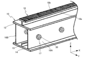
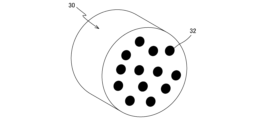
- FIG. 2 is a perspective view showing a steel box girder that constitutes part of the superstructure of the box girder bridge of FIG. 3 is an enlarged perspective view of the breathable waterproof member of FIG. 2 .
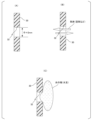
- FIG. 4A to 4C are diagrams for explaining the function of a breathable waterproof member.
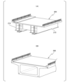
- FIG. 13 is a diagram showing another example of a box girder bridge.
- FIG. 1 shows a perspective view with some parts omitted of the superstructure of a box girder bridge 100 according to one embodiment.
- the box girder bridge 100 is a continuous girder bridge (or a simple girder bridge), and its superstructure comprises a steel box girder 10 and a concrete deck 20 provided on the steel box girder 10.
- the superstructure including the steel box girder 10 and the concrete deck 20 is supported from below by the substructure (not shown).
- the direction of gravity is defined as the Z-axis direction
- the bridge axis direction in a plane perpendicular to the direction of gravity is defined as the X-axis direction
- the width direction perpendicular to the bridge axis direction is defined as the Y-axis direction.
- the steel box girder 10 is provided with an upper flange 12 and a lower flange 14 that are arranged facing each other and spaced apart in the Z-axis direction, and a pair of webs 16A, 16B that are arranged facing each other and spaced apart in the Y-axis direction (width direction) between the upper flange 12 and the lower flange 14 and connect the upper flange 12 and the lower flange 14.
- the upper flange 12 and the lower flange 14 are both made of rectangular steel plates of a certain thickness that are elongated in one axis direction.
- the lower flange 14 is arranged parallel to the XY plane with the X-axis direction as its longitudinal direction.
- Each of the pair of webs 16A, 16B is made of rectangular steel plates of a certain thickness that are elongated in one axis direction, and is arranged on the lower flange 14 parallel to the XZ plane with the X-axis direction as its longitudinal direction.
- the upper flange 12 is arranged parallel to the lower flange on the pair of webs 16A, 16B.
- each of the pair of webs 16A, 16B is welded to the upper surface of the lower flange 14, and the lower surface of the upper flange 12 is welded to the upper end surface of each of the pair of webs 16A, 16B.
- a pair of side walls of the hollow steel box girder 10 are formed by the pair of webs 16A, 16B.
- both the upper flange 12 and the lower flange 14 protrude somewhat in the width direction beyond the pair of webs 16A, 16B, but at least one of them does not have to protrude.
- the internal space of the steel box girder 10 surrounded by the upper flange 12, the lower flange 14 and the pair of webs 16A, 16B is partitioned by steel plates with sufficient rigidity called diaphragms arranged at predetermined intervals in the bridge axis direction, and essentially multiple closed spaces are formed inside the steel box girder 10.
- the multiple diaphragms arranged at predetermined intervals inside prevent the cross-sectional shape of the steel box girder 10 from changing.
- a reinforcing rib 15 is provided on the upper surface of the lower flange 14, extending in the X-axis direction at the center of the width of the lower flange 14.
- a T-shaped steel 18 with an outer protrusion is arranged on the upper surface of the upper flange 12, at the center of the width of the upper flange 12, with its longitudinal direction being the bridge axis direction.
- the T-shaped steel with outer projections 18 is attached to the top surface of the upper flange 12 by welding, but it can be either factory-welded or on-site-welded, or a combination of factory-welded and on-site-welded.
- the attachment method is not limited to welding, and it can be joined with bolts via a joining member such as an angle steel material.
- buckling of the upper flange 12 is prevented by the reinforcing effect of the T-shaped steel 18 with external projections attached to the widthwise center of the upper surface of the upper flange 12.
- the reason why the attachment position of the T-shaped steel 18 with external projections to the upper surface of the upper flange 12 is the widthwise center of the upper flange 12 is to efficiently prevent buckling of the upper flange 12 over its entire surface.
- the T-shaped steel with external projections 18 has a flange 18a that has a reinforcing effect on the steel box girder 10, so the thickness of the upper flange 12 can be made thinner accordingly.
- linear external projections 18b are provided at predetermined intervals along the longitudinal direction of the T-shaped steel with external projections 18.
- the external projections 18b are arranged in a direction perpendicular to the longitudinal direction (bridge axis direction) of the T-shaped steel with external projections 18, and their cross-sectional shape is not particularly limited.
- the T-shaped steel with external projections 18 is actually embedded inside the concrete deck 20.
- the concrete deck 20 is formed by pouring concrete on the upper surface of the upper flange 12 from the upper surface of the flange 18a of the T-shaped steel 18 with external projections to a specified height above. That is, in this way, the joint of the concrete deck 20 to the steel box girder 10 is constructed.
- the outer projections 18b provided on the upper surface of the flange 18a of the T-shaped steel 18 with external projections provide strong resistance to horizontal shear forces in the bridge axis direction due to adhesion, support pressure, and friction with the concrete, and the T-shaped steel 18 with external projections exhibits anti-slip performance against horizontal shear forces in the bridge axis direction equal to or greater than that of a stud dowel.
- the T-shaped steel 18 with external projections can also resist upward lift forces due to the support pressure between the underside of the flange 18a and the concrete 52, and in this respect also exhibits anti-slip performance.
- one T-shaped steel with an outer protrusion 18 is provided, but two or more may be provided depending on the width dimension of the upper flange 12.
- a stud dowel to prevent slippage may be provided at the joint between the steel box girder and the concrete deck without providing a T-shaped steel with an outer protrusion.
- a pair of webs 16A and 16B which respectively constitute both side walls in the width direction (Y axis direction) perpendicular to the bridge axis direction (X axis direction) of the steel box girder 10, have a plurality of through holes 17 formed at a predetermined interval in the bridge axis direction.
- the plurality of through holes 17 are formed at approximately the center position in the height direction of each web (or a position close to the upper flange 12).
- the through holes 17 are arranged in positions facing each other in one web 16A and the other web 16B.
- the plurality of through holes 17 may be arranged alternately in positions shifted from each other in the bridge axis direction in one web 16A and the other web 16B.
- the plurality of through holes 17 may be arranged not only in the bridge axis direction but also in the height direction in one web 16A and the other web 16B. In this case, the through holes 17 in one web 16A and the other web 16B may or may not face each other. Depending on where the steel box girder is installed, multiple through holes may be provided only in one of the webs, 16A and 16B. In this case, a ventilation means such as a ventilator may be used in combination.
- Each of the multiple through holes 17 is, for example, a circular hole with a diameter of about 30 mm.
- a breathable waterproof member 30 as shown in FIG. 3 is fitted tightly into each through hole 17.
- the through holes formed in web 16A or web 16B are not limited to circular holes, but may be elliptical, polygonal, or other shaped holes.
- the breathable waterproof member (main body) 30 is a disk-shaped (or cylindrical) member made of silicone rubber, a type of thermosetting elastomer, and has a plurality of ventilation holes 32 formed over the entire surface of its end face.
- the diameter of the breathable waterproof member 30 is set to be somewhat larger than the diameter of the through hole 17. This is because the breathable waterproof member 30 is compressed in the radial direction and fitted into the through hole 17, and the elasticity of the breathable waterproof member 30 is utilized to prevent a gap from being generated between the outer surface of the breathable waterproof member 30 and the inner surface of the through hole 17.
- elasticity refers to the property of an individual that is distorted when stress is applied but returns to its original dimensions when the load is removed, but in this specification, the term “elasticity” is used as a general term for shape elasticity (elasticity that appears due to deformation without volume change), elasticity, stretchability, deformability, etc. Hereinafter, it will also be referred to as stretchability (elasticity) as appropriate.
- a tapered portion may be provided on at least a part of the outer circumferential surface of the breathable waterproof member 30.
- the breathable waterproof member 30 may also be conical. In this case, it is preferable to set the diameter of the outer end face and the diameter of the inner end face so that the air hole is not crushed. The diameter may be set so that it gradually becomes larger toward the inside, or vice versa. In the former case, the breathable waterproof member is fitted from the inside of the box girder. In the latter case, it is fitted from the outside.
- the breathable waterproof member (main body) 30 has a plurality of ventilation holes 32 formed therein, which connect one side surface (one end surface) with the opposite side surface (the other end surface).
- the plurality of ventilation holes 32 are through holes with a circular cross section, and are arranged across the entire area (whole surface) of the end surface.
- the diameter of the ventilation holes 32 is set to about 2 mm, as an example.
- the arrangement of the ventilation holes within the end surface may be arbitrary.
- Parts (A), (B), and (C) of FIG. 4 show the breathable waterproof member 30 in a schematic form.
- the breathable waterproof member 30 has a vent hole (round hole) 32 with a diameter of 2 mm.
- gas (air, etc.) can enter and exit through the vent hole 32, but water (liquid) attached to the surface (end surface) of the breathable waterproof member 30 cannot pass through the vent hole 32.
- FIG. 4(C) water attached to the surface becomes a water mass (water droplets) due to the property (surface tension) of trying to make the surface as small as possible.
- the diameter (2 mm) of the vent hole 32 is smaller than the diameter of the water mass (water droplet), so the water mass (water droplet) cannot enter the air hole 32.
- the contact angle of water on the silicon surface is greater than 90 degrees, the water masses (droplets) barely come into contact with the breathable waterproof member 30, as shown in FIG. 4(C).
- the breathable waterproof member 30 allows air to enter and exit while preventing water from entering through the ventilation holes 32.
- the breathable waterproof member 30 has multiple ventilation holes 32, so air can enter and exit through the multiple ventilation holes 32 at the same time. Note that the ventilation holes 32 only need to be large enough to prevent water from entering, and their diameter should be approximately 1 mm to 2.8 mm.
- each ventilation hole 32 is set to a dimension that can prevent the intrusion of water droplets that adhere to one end face of the breathable waterproof member 30 (the face that faces the outer surface of the steel box girder 10 when the breathable waterproof member 30 is fitted into the through hole 17 of the web 16A (or 16B)).
- the shape (including size) of the water droplets is determined according to the surface tension of the water and the critical surface tension of the surface of the breathable waterproof member 30. In other words, the shape of the water droplets is determined according to the contact angle of water on the surface of the breathable waterproof member (on one end face).
- the contact angle means the angle that the liquid surface forms with the solid surface (here, the silicone rubber surface) at the boundary line where the three phases (solid phase, liquid phase, gas phase) come into contact when the solid surface (here, the silicone rubber surface) is in contact with the liquid (here, water) and gas (here, air).
- the diameter of the ventilation hole 32 may be changed depending on the contact angle of water (liquid) on the surface of the breathable waterproof member (on one end face), i.e., the material of the outer end face of the breathable waterproof member 30.
- the above-mentioned range of 1 mm to 2.8 mm can also be changed, with at least one of the lower limit and upper limit becoming larger or smaller depending on the contact angle.
- the cross-sectional shape of the ventilation hole 32 is not limited to a circle, but may be an ellipse, a polygon, or other shape, as long as it is large enough to prevent the intrusion of water droplets adhering to one end face of the breathable waterproof member 30.
- the diameter of the ventilation hole of the breathable waterproof member may be different between the outer end face and the inner end face.
- the above-mentioned diameter range of the ventilation hole 32 needs to be satisfied by at least the ventilation hole on the outer end face, and the diameter of the ventilation hole on the inner end face may be outside that range.
- the shape of the ventilation hole may be different between the outer end face and the inner end face.
- the breathable waterproof member 30 is a disk-shaped (or cylindrical) member, but is not limited thereto.
- the through-hole 17 formed in the web 16A or the web 16B is a shape other than a circle
- the breathable waterproof member 30 may have a shape that allows it to be fitted into the through-hole without any gaps.
- the breathable waterproof member does not need to be entirely plate-shaped or column-shaped, and it is sufficient that at least one end has a three-dimensional shape that can be inserted into the through-hole.
- a steel box girder is used as a hollow structure, and the case where the liquid to be blocked (prevented) by the breathable waterproof member is water has been described.
- the liquid to be blocked (prevented) by the breathable waterproof member may be a liquid other than water.
- waterproof included in the term breathable waterproof member used in this specification is not a term that only refers to water. Therefore, the water described so far is an example of a liquid, and for example, water droplets are an example of a droplet.
- a droplet means a mass of liquid held together by surface tension, in other words, a grain or drop of liquid.
- the breathable waterproof member 30 of this embodiment allows air to flow between the outside of one end face and the outside of the other end face through the ventilation holes 32, and also prevents (or prevents) water from entering the ventilation holes 32.
- a plurality of through holes 17 are formed in each of the pair of webs 16A and 16B, and a breathable waterproof member 30 is attached to each of the plurality of through holes 17. Therefore, air can flow in and out between the inside and outside of the steel box girder 10 through each of the plurality of breathable waterproof members 30 attached to the web 16A and the plurality of breathable waterproof members 30 attached to the web 16B, thereby providing sufficient ventilation inside the steel box girder 10.
- the intrusion of water into the steel box girder 10 through the breathable waterproof member 30 is effectively prevented or blocked by the breathable waterproof member 30.
- the mounting target of the breathable waterproof member 30 is not limited to a steel box girder, but may be a concrete box girder, or a box girder of a composite structure made of steel and concrete.
- the box girder bridge to which the breathable waterproof member of the above embodiment is applied may have two or more steel box girders (or concrete box girders) 210 arranged in parallel, such as the parallel two-box girder bridge 200 shown in FIG. 5(A).
- box girder bridge to which the breathable waterproof member of the above embodiment is applied may have an RC (reinforced concrete) deck, a steel deck, or a composite deck, not limited to a concrete deck.
- the box girder bridge may have a structure in which the deck and the box girder are integrated, such as the PC girder bridge 300 shown in FIG. 5(B).
- the breathable waterproof member 30 is made of silicone rubber (SI), a type of thermosetting elastomer.
- the material of the breathable waterproof member may be a thermosetting elastomer other than silicone rubber, or a thermoplastic elastomer. Both thermosetting elastomers and thermoplastic elastomers are elastic polymeric materials.
- Thermosetting elastomers include silicone rubber, natural rubber (NR), fluororubber (FKM), styrene rubber (SBR), butadiene rubber (BR), ethylene propylene rubber (EPM), ethylene propylene diene rubber (EPDM), urethane rubber (U), acrylic rubber (ACM), etc.
- Thermoplastic elastomers include olefin-based (TPO, TPV), styrene-based (TPS), urethane-based (TPU), ester-based (TPC, TPEE), polyvinyl chloride-based (TPVC), amide-based (TPAE), etc. It is desirable for the material of the breathable waterproof member according to the above embodiment to be one whose surface has a contact angle of water of greater than 90 degrees.
- the material of the breathable waterproof member is not limited to resin such as elastomer.
- the breathable waterproof member is preferably a material having elasticity.
- the breathable waterproof member may be a solid material that does not have elasticity. Even if the material is not elastic, when inserting the breathable waterproof member into the through hole of the box girder, an adhesive or the like may be applied to the inner surface of the through hole to prevent gaps from occurring. Furthermore, a filler or the like may be used instead of or together with the adhesive to prevent gaps from occurring between the inner surface of the through hole and the breathable waterproof member.
- the box girders that make up a box girder bridge have been taken up as an example of a hollow structure with a closed space formed inside to which the breathable waterproof member according to the above embodiment can be applied, but the hollow structures to which the breathable waterproof member can be applied are not limited to box girders. Any hollow structure that requires measures to prevent internal condensation can be used with the breathable waterproof member according to the above embodiment.
- the breathable waterproof member according to the above embodiment is particularly effective when applied to hollow structures in which small holes of about 3 mm or less cannot be directly drilled.
- the breathable waterproof member 30 according to the above embodiment can be mass-produced by using a 3D printer or by micromachining to create a mold or wax mold.
- the breathable waterproof member can be directly manufactured using a 3D printer that performs additive processing, or multiple ventilation holes can be made in a base material made of a solid material such as resin by subtractive processing or by drilling, etc.
Landscapes
- Engineering & Computer Science (AREA)
- Architecture (AREA)
- Civil Engineering (AREA)
- Structural Engineering (AREA)
- Bridges Or Land Bridges (AREA)
Abstract
中空構造体(10)を取り付け対象物とする通気防水部材(30)は、固体材料から成り、中空構造体に形成された貫通孔(17)に挿入状態で取り付け可能な所定の立体形状を有し、水(液体)の侵入を防止可能な複数の通気孔を有する。これにより、中空構造体の内部への水の侵入を防止しつつ、中空構造体の内部の換気が可能になる。
Description
本発明は、通気防水部材、箱桁及び箱桁橋に係り、特に中空構造体を取り付け対象物とする通気防水部材、該通気防水部材が取り付けられた箱桁、及び該箱桁を備えた箱桁橋に関する。
従来、単純桁や連続桁における鋼製若しくは鋼とコンクリートとによる合成構造の箱桁の内部は、密閉構造に近いものであるため、外面よりも腐食環境が良いが、箱桁内部に一旦こもった湿気が保持されると、外気温度との温度差により結露が生じて、これが錆の原因となることがある。そこで、箱桁内部の防錆方法としては、通常、箱桁内面に塗装が施されている。しかし、この場合、箱桁の内部には、有機塗料から発生するガスがこもり易いという不都合がある。
かかる不都合を改善する手段として、例えば、特許文献1に開示されるように、箱桁において、一つまたは複数の結露防止用通気孔を腹板(側壁)に設けることが考えられる。
しかしながら、特許文献1に開示される結露防止用通気孔は、該文献の一部に「結露防止用通気孔には、動物による箱桁内部への侵入を阻止する防護網が設けられている」との記載があることから、その直径が鳥などの小動物の箱桁内部への侵入が可能な大きさを有しているものと思われる。したがって、特許文献1に開示される結露防止用通気孔では、水の侵入を防止することが困難である。この一方、桁に用いる鋼板にはφ30mm程度より小さな孔を空けることは現時点では困難である。
本発明の第1の態様によれば、中空構造体を取り付け対象物とする通気防水部材であって、固体材料から成り、前記中空構造体に形成された貫通孔に挿入状態で取付可能な所定の立体形状を有する本体と、前記本体に設けられ、液体の侵入を防止可能な複数の通気孔と、を有する通気防水部材が、提供される。
本発明の第2の態様によれば、互いに対向して配置され、それぞれ一軸方向に延びる一対の側壁を有する中空構造の箱桁であって、前記一対の側壁の少なくとも一方に所定の配置で複数の貫通孔が形成され、該複数の貫通孔のそれぞれに第1の態様に係る通気防水部材が取り付けられている箱桁が提供される。
本発明の第3の態様によれば、第2の態様に係る箱桁と、前記箱桁の上に前記一軸方向を橋軸方向として取り付けられた床版と、を備える箱桁橋が、提供される。
以下、図1~図4に基づいて、本発明の一実施形態について説明する。図1には、一実施形態に係る箱桁橋100の上部構造が一部省略した斜視図にて示されている。箱桁橋100は、連続桁橋(又は単純桁橋)であり、その上部構造は、鋼箱桁10と、鋼箱桁10の上に設けられたコンクリート床版20とを備えている。鋼箱桁10及びコンクリート床版20を含む上部構造は、下部構造(不図示)によって下から支持されている。
以下では、図1に示されるように、重力方向をZ軸方向とし、重力方向に直交する面内で橋軸方向をX軸方向、橋軸方向に直交する幅方向をY軸方向として説明を行う。
鋼箱桁10は、図2に示されるように、Z軸方向に離れてかつ対向して配置された上フランジ12及び下フランジ14と、上フランジ12と下フランジ14との間にY軸方向(幅方向)に離れてかつ対向して配置され、上フランジ12と下フランジ14を連結する一対のウェブ16A、16Bと、を備えている。上フランジ12及び下フランジ14は、ともに一軸方向に細長い矩形の所定厚さの鋼板から成る。下フランジ14は、X軸方向を長手方向としてXY平面に平行に配置されている。一対のウェブ16A、16Bのそれぞれは、一軸方向に細長い矩形の所定厚さの鋼板から成り、下フランジ14上にX軸方向を長手方向としてXZ面に平行に配置されている。一対のウェブ16A、16B上に上フランジ12が、下フランジに平行に配置されている。
一対のウェブ16A、16Bそれぞれの下端面は下フランジ14の上面に溶接され、一対のウェブ16A、16Bそれぞれの上端面に上フランジ12の下面が溶接されている。これによって中空の鋼箱桁10が形成されている。本実施形態では、一対のウェブ16A、16Bによって中空の鋼箱桁10の一対の側壁が構成されている。
本実施形態では、上フランジ12及び下フランジ14は、ともに一対のウェブ16A、16Bより幅方向に幾分張り出しているが、少なくとも一方は、張り出さなくても良い。上フランジ12、下フランジ14及び一対のウェブ16A、16Bに囲まれる鋼箱桁10の内部空間は、橋軸方向に関して所定間隔で配置されたダイヤフラムと呼ばれる十分な剛性を有する鋼板によって仕切られており、鋼箱桁10の内部には実質的に複数の閉空間が形成されている。内部に所定間隔で配置された複数のダイヤフラムによって鋼箱桁10の横断面形状が変化するのが防止されている。
下フランジ14の上面には下フランジ14の幅方向中央部にX軸方向に延びる補強リブ15が設けられている。また、上フランジ12の上面には、外面突起付きT形鋼18が上フランジ12の幅方向中央部に橋軸方向を長手方向として配置されている。
外面突起付きT形鋼18は、本実施形態では上フランジ12の上面に溶接により取り付けられているが、工場溶接、現場溶接のどちらでも良く、また、工場溶接、現場溶接を併用しても良い。また、取り付け方法は溶接に限定されず、例えばアングル鋼材等の接合部材を介してボルトで接合しても良い。
本実施形態では、上フランジ12の上面の幅方向中央部に取り付けられた外面突起付きT形鋼18による補強効果によって上フランジ12の座屈が防止されている。なお、外面突起付きT形鋼18の上フランジ12の上面への取り付け位置を、上フランジ12の幅方向中央部としている理由は、上フランジ12の座屈を全面にわたって効率的に防止するためである。
外面突起付きT形鋼18は、鋼箱桁10の補強効果を有するフランジ18aを有しているので上フランジ12の厚さをその分薄くすることができる。フランジ18aの上面には、線状の外面突起18bが外面突起付きT形鋼18の長手方向に沿って所定の間隔で設けられている。外面突起18bは、外面突起付きT形鋼18の長手方向(橋軸方向)と直交する方向に配置され、その断面形状は特に限定されない。外面突起付きT形鋼18は実際にはコンクリート床版20の内部に埋め込まれている。
外面突起付きT形鋼18のフランジ18aの上面から所定の高さだけ上方まで、上フランジ12の上面にコンクリートを打設してコンクリート床版20を形成している。すなわち、このようにして鋼箱桁10に対するコンクリート床版20の接合部が構成されている。外面突起付きT形鋼18のフランジ18a上面に設けられた外面突起18bは、コンクリートとの付着・支圧・摩擦により橋軸方向の水平せん断力に対する強力な抵抗となり、外面突起付きT形鋼18は橋軸方向の水平せん断力に対してスタッドジベルと同等以上のずれ止め性能を発揮する。また、外面突起付きT形鋼18は、上揚力に対してもフランジ18aの下面とコンクリート52との支圧で抵抗することができ、この点でもずれ止め性能を発揮する。
本実施形態では、外面突起付きT形鋼18は1つ設けられているが、上フランジ12の幅方向の寸法に応じて2つ以上設けても良い。勿論、外面突起付きT形鋼を設けることなく、鋼箱桁とコンクリート床版との接合部にずれ止め防止用のスタッドジベルを設けても良い。
鋼箱桁10の橋軸方向(X軸方向)に直交する幅方向(Y軸方向)の両側壁をそれぞれ構成する一対のウェブ16A、16Bのそれぞれには、複数の貫通孔17が橋軸方向に離れて所定間隔で形成されている。本実施形態では、複数の貫通孔17は、それぞれのウェブの高さ方向のほぼ中央の位置(又は上フランジ12の近い位置)に形成されている。本実施形態では、一方のウェブ16Aと他方のウェブ16Bには、互いに対向する位置に貫通孔17が配置されている。これに限らず、一方のウェブ16Aと他方のウェブ16Bには、橋軸方向に関して互いにずれた位置に交互に複数の貫通孔17を配置しても良い。一方のウェブ16Aと他方のウェブ16Bには、橋軸方向のみならず高さ方向に離れて複数の貫通孔17を配置しても良い。この場合、一方のウェブ16Aと他方のウェブ16Bで貫通孔17は互いに対向していても良いし、対向していなくても良い。鋼箱桁が設置される場所によっては、ウェブ16Aと他方のウェブ16Bの一方にのみ貫通孔を複数設けても良い。この場合、換気扇などの換気手段を併用しても良い。
複数の貫通孔17のそれぞれは一例として直径30mm程度の円形の孔である。それぞれの貫通孔17には、図3に示されるような通気防水部材30が隙間なく嵌め込まれている。ウェブ16A又はウェブ16Bに形成される貫通孔は円形の孔に限らず、楕円形、多角形その他の形状の孔であっても良い。
通気防水部材(本体)30は、本実施形態では、熱硬化性エラストマーの一種であるシリコンゴムを材料とする円板(円盤)状(又は円柱状)の部材であり、その端面には、複数の通気孔32が全面に渡って形成されている。通気防水部材30の直径は、貫通孔17の直径より幾分大きく設定されている。これは、通気防水部材30をラジアル方向に圧縮して貫通孔17に嵌め込むことで、通気防水部材30の弾性を利用して通気防水部材30の外周面と貫通孔17の内周面との間に隙間を生じさせないようにするためである。ここで、「弾性」とは応力を加えるとひずみが生じるが、除荷すれば元の寸法に戻る個体の性質を指すが、本明細書では、形状弾性(体積変化を伴わない変形によって現れる弾性)、弾力性、伸縮性あるいは変形性などの総称として「弾性」なる用語を用いている。以下では、適宜、伸縮性(弾性)とも表記する。
なお、通気防水部材30の貫通孔17への圧入(嵌め込み)を容易にするため、通気防水部材30の外周面の少なくとも一部にテーパ部を設けても良い。通気防水部材30を、円錐状にしても良い。この際、通気孔がつぶれないよう外側端面の直径と内側端面の直径を設定することが好ましい。内側に向かうに従って直径が次第に大きくなるように設定しても良いし、その逆でも良い。前者では箱桁内側から通気防水部材をはめ込むことになる。後者は逆に外側からはめ込むことになる。
通気防水部材(本体)30には、図3に示されるように、一側の面(一端面)とその反対側の面(他端面)とを連通する複数の通気孔32が形成されている。複数の通気孔32は、一例として断面が円形の貫通孔であり、端面の全域(全面)に渡って配置されている。本実施形態では、通気孔32の直径は、一例として、2mm程度に設定されている。端面内での通気孔の配置は任意で良い。
ここで、通気防水部材30の役割について説明する。図4の(A)部、(B)部、及び(C)部には、通気防水部材30が模式化して示されている。図4(A)に示されるように、通気防水部材30には、直径2mmの通気孔(丸孔)32が形成されている。このため、図4(B)に示されるように、通気孔32を介して気体(空気など)の出入りは可能であるが、通気防水部材30の表面(端面)に付着した水(液体)は、通気孔32を通過することはできない。理由は、次の通りである。図4(C)に示されるように、表面に付着した水は、その表面をできるだけ小さくしようとする性質(表面張力)によって水の塊(水玉)となる。本実施形態では、通気孔32の直径(2mm)が、その水の塊(水玉)の直径より小さいため、その水の塊(水玉)は通気孔32に侵入することができないからである。また、シリコン表面上での水の接触角は90度より大きいため、水の塊(水玉)は、図4(C)に示されるように、通気防水部材30に殆ど接触しない。このように、通気防水部材30は通気孔32によって水の侵入を防止しつつ空気を出入りさせることができる。また、実際には、通気防水部材30には通気孔32が複数形成されているので、その複数の通気孔32を介して一度に空気を出入りさせることができる。なお、通気孔32は、水の侵入を阻止できる大きさであれば足り、その直径は1mm~2.8mm程度であれば良い。
それぞれの通気孔32の直径は、通気防水部材30の一方の端面(通気防水部材30がウェブ16A(又は16B)の貫通孔17に嵌め込まれた際に、鋼箱桁10の外面側となる方の面)に付着する水玉の侵入を阻止できる寸法に設定されている。水玉の形状(大きさを含む)は、水の表面張力及び通気防水部材30表面の臨界表面張力に応じて定まる。換言すれば、水玉の形状は、通気防水部材表面上(一方の端面上)での水の接触角に応じて定まる。ここで、接触角とは、固体表面(ここではシリコンゴム表面)が液体(ここでは水)及び気体(ここでは空気)と接触しているとき、この3相(固相、液相、気相)の接触する境界線において液体面が固体面と成す角度を意味する。通気防水部材表面上(一方の端面上)での水(液体)の接触角、すなわち通気防水部材30の外側端面の材料に応じて、通気孔32の直径を変更しても良い。すなわち、上述した1mm~2.8mmの範囲も、接触角に応じて下限値と上限値との少なくとも一方が大きくなったり小さくなったり変化し得る。
なお、通気孔32は、通気防水部材30の一方の端面に付着する水玉の侵入を阻止できる大きさであればその断面形状は、円形に限らず、楕円形、多角形その他の形状であっても良い。通気防水部材の通気孔の直径は、外側端面と内側端面とで異なっていても良い。上述した通気孔32の直径の範囲は、少なくとも外側端面の通気孔が満たしていれば良く、内側端面の通気孔の直径がその範囲を外れていても良い。通気孔の形状は、外側端面と内側端面とで異なっていても良い。
本実施形態では、通気防水部材30は円板(円盤)状(又は円柱状)の部材であるとしたが、これに限られない。ウェブ16A又はウェブ16Bに形成された貫通孔17が円形以外の形状である場合、通気防水部材30は、その貫通孔に隙間なく嵌め込むことができる形状であれば良い。また、通気防水部材は、全体が板状又は柱状である必要なく、少なくとも一側の端部が貫通孔に挿入可能な立体形状を有していれば足りる。
本実施形態では、中空構造体として、鋼箱桁を取り上げ、これに応じて通気防水部材による侵入阻止(侵入防止)の対象となる液体が水である場合について説明したが、通気防水部材の侵入阻止(侵入防止)の対象となる液体は水以外の液体であっても良い。すなわち、本明細書で使用する通気防水部材という用語に含まれる「防水」は水のみを対象とする用語ではない。したがって、これまでに説明した水は液体の一例であり、例えば水玉は、液滴の一例である。なお、液滴とは、表面張力でまとまった液体の塊、別言すれば液体の粒、滴りを意味する。
本実施形態では、中空構造体として、鋼箱桁を取り上げ、これに応じて通気防水部材による侵入阻止(侵入防止)の対象となる液体が水である場合について説明したが、通気防水部材の侵入阻止(侵入防止)の対象となる液体は水以外の液体であっても良い。すなわち、本明細書で使用する通気防水部材という用語に含まれる「防水」は水のみを対象とする用語ではない。したがって、これまでに説明した水は液体の一例であり、例えば水玉は、液滴の一例である。なお、液滴とは、表面張力でまとまった液体の塊、別言すれば液体の粒、滴りを意味する。
以上説明したように、本実施形態に係る通気防水部材30によると、通気孔32を介して一側の端面外部と他側の端面外部との間で空気を出入りさせることができるとともに、通気孔32内部への水の侵入を阻止(ないしは防止)することができる。
また、本実施形態に係る鋼箱桁10によると、一対のウェブ16A、16Bのそれぞれに、複数の貫通孔17(直径30mm程度)が形成されており、複数の貫通孔17のそれぞれに通気防水部材30が装着されている。このため、ウェブ16Aに装着された複数の通気防水部材30及びウェブ16Bに装着された複数の通気防水部材30のそれぞれを介して鋼箱桁10内部と外部との間で空気の出入りが可能になり、これにより鋼箱桁10内部の換気が十分に行われる。この一方、通気防水部材30を介した鋼箱桁10内部への水の侵入は、通気防水部材30によって効果的に防止ないし阻止される。このため、鋼箱桁10の内部に湿気がこもった状態、ひいては外気温度との温度差により結露が生じる状態が発生するのを効果的に抑制ないしは防止することが可能になる。また、鋼箱桁10の内部での結露の発生が効果的に抑制ないしは防止されるので、これに起因する錆の発生も無視できる程度となる。したがって、鋼箱桁10内面を必ずしも塗装しなくても良くなる。仮に、鋼箱桁10内面を塗装する場合であっても従来に比べて塗り直しの回数を低減することができる。
なお、上記実施形態では、鋼箱桁10が通気防水部材30の取付対象である場合について説明したが、通気防水部材30の取付対象は、鋼箱桁に限らずコンクリート箱桁、あるいは鋼とコンクリートとによる合成構造の箱桁でも良い。上記実施形態の通気防水部材が適用される箱桁橋は、図5(A)に示される並列2箱桁橋200のように並列に配置された鋼箱桁(又はコンクリート箱桁)210を2つ以上有していても良い。また、上記実施形態の通気防水部材が適用される箱桁橋は、コンクリート床版に限らず、RC(鉄筋コンクリート)床版、鋼製床版、あるいは合成床版を有していても良い。この他、箱桁橋は、図5(B)に示されるPC桁橋300のように床版と箱桁が一体化された構造を有していても良い。
なお、上記実施形態では、熱硬化性エラストマーの一種であるシリコンゴム(SI)を材料とする通気防水部材30について説明したが、通気防水部材の材料は、シリコンゴム以外の熱硬化性エラストマーは勿論、熱可塑性エラストマーであっても良い。熱硬化性エラストマー及び熱可塑性エラストマーは、いずれも弾性のある高分子材料である。
熱硬化性エラストマーとしては、シリコンゴムの他、天然ゴム(NR)、フッ素ゴム(FKM)、スチレンゴム(SBR)ブタジエンゴム(BR)、エチレンプロピレンゴム(EPM)、エチレンプロピレンジエンゴム(EPDM)、ウレタンゴム(U)、アクリルゴム(ACM)などが挙げられる。また、熱可塑性エラストマーとしては、オレフィン系(TPO、TPV)、スチレン系(TPS)、ウレタン系(TPU)、エステル系(TPC、TPEE)、塩化ビニル系(TPVC)、アミド系(TPAE)などが挙げられる。上記実施形態に係る通気防水部材の材料としては、その表面上での水の接触角が90度より大きい材料であることが望ましい。
上記実施形態に係る通気防水部材と同様の機能を持たせることが可能であれば、通気防水部材の材料は、エラストマーなどの樹脂に限られない。上記実施形態の説明からもわかるように、通気防水部材は、伸縮性(弾性)を有する材料であることが好ましい。ただし、通気防水部材は、伸縮性(弾性)を有しない固体材料であっても良い。伸縮性(弾性)がない材料であっても、箱桁の貫通孔に通気防水部材を挿入する際、貫通孔の内周面に例えば接着剤などを塗っておいても良く、これにより隙間を生じさせないようにしても良い。また、接着剤に代えて、あるいは接着剤とともに充填材等を用いて貫通孔の内周面と通気防水部材との間に隙間を生じさせないようにしても良い。
なお、これまでは、上記実施形態に係る通気防水部材が適用される、内部に閉空間が形成された中空の構造体の一例として、箱桁橋を構成する箱桁を取り上げて説明したが、通気防水部材の適用対象となる中空構造体は箱桁に限られない。内部の結露対策が必要な中空構造体であれば、上記実施形態に係る通気防水部材の適用対象となる。3mm程度以下の小さい孔を直接明ける事が出来ないような中空構造体に適用する場合に、上記実施形態に係る通気防水部材は特に大きな効果を発揮する。
上記実施形態に係る通気防水部材30は、3Dプリンタを用いて、あるいは微細加工によって、金型若しくはワックス型を作製することで、その金型若しくはワックス型を用いて大量生産することも可能である。付加加工を行う3Dプリンタで直接通気防水部材を製造しても良いし、除去加工あるいはドリル等によって、樹脂などの固体材料から成る母材に複数の通気孔を空けても良い。
10…鋼箱桁、16A…ウェブ、16B…ウェブ、17…貫通孔、20…コンクリート床版、30…通気防水部材(本体)、32…通気孔、100…箱桁橋。
Claims (17)
- 中空構造体を取り付け対象物とする通気防水部材であって、
固体材料から成り、前記中空構造体に形成された貫通孔に挿入状態で取付可能な所定の立体形状を有する本体と、
前記本体に設けられ、液体の侵入を防止可能な複数の通気孔と、
を有する、通気防水部材。 - 請求項1に記載の通気防水部材において、
前記本体は、弾性を有する前記固体材料から成り、その弾性により前記貫通孔に圧入状態で取付られる、通気防水部材。 - 請求項1又は2に記載の通気防水部材において、
前記固体材料は、エラストマーである通気防水部材。 - 請求項3に記載の通気防水部材において、
前記固体材料は、熱硬化性エラストマーである通気防水部材。 - 請求項4に記載の通気防水部材において、
前記固体材料は、シリコンゴムである通気防水部材。 - 請求項1~5のいずれか一項に記載の通気防水部材において、
前記所定の立体形状は、一面と反対側の他面とを有する所定厚さの板状又は柱状である通気防水部材。 - 請求項6に記載の通気防水部材において、
前記通気孔は、一面から前記他面に向かって伸びる通気防水部材。 - 請求項1~7のいずれか一項に記載の通気防水部材において、
前記通気孔は、断面円形の貫通孔である通気防水部材。 - 請求項8に記載の通気防水部材において、
前記通気孔の直径は、前記本体の表面に付着する液滴より小さい通気防水部材。 - 請求項9に記載の通気防水部材において、
前記液滴の形状は、液体の表面張力と前記本体の前記表面の臨界表面張力とに基づいて定まる通気防水部材。 - 請求項9に記載の通気防水部材において、
前記液滴の形状は、前記本体の前記表面上での液体の接触角に応じて定まる通気防水部材。 - 請求項9~11のいずれか一項に記載の通気防水部材において、
前記通気孔の直径は、1~2.8mm程度である通気防水部材。 - 互いに対向して配置され、それぞれ一軸方向に延びる一対の側壁を有する中空構造の箱桁であって、
前記一対の側壁の少なくとも一方に所定の配置で複数の貫通孔が形成され、該複数の貫通孔のそれぞれに請求項1~12のいずれか一項に記載の通気防水部材が取り付けられている箱桁。 - 請求項13に記載の箱桁において、
前記一対の側壁のそれぞれに所定の配置で複数の貫通孔が形成されている箱桁。 - 請求項14に記載の箱桁において、
前記一対の側壁の一方と他方に互いに対向して複数の貫通孔が形成されている箱桁。 - 請求項14に記載の箱桁において、
前記一対の側壁の一方と他方にそれぞれ形成された前記複数の貫通孔は、前記一軸方向及び前記側壁の面内で前記一軸方向に垂直な高さ方向の少なく一方に関して、交互に配置されている箱桁。 - 請求項13~16のいずれか一項に記載の箱桁と、
前記箱桁の上に前記一軸方向を橋軸方向として取り付けられた床版と、を備える箱桁橋。
Priority Applications (1)
| Application Number | Priority Date | Filing Date | Title |
|---|---|---|---|
| PCT/JP2023/024937 WO2025009101A1 (ja) | 2023-07-05 | 2023-07-05 | 通気防水部材、箱桁及び箱桁橋 |
Applications Claiming Priority (1)
| Application Number | Priority Date | Filing Date | Title |
|---|---|---|---|
| PCT/JP2023/024937 WO2025009101A1 (ja) | 2023-07-05 | 2023-07-05 | 通気防水部材、箱桁及び箱桁橋 |
Publications (1)
| Publication Number | Publication Date |
|---|---|
| WO2025009101A1 true WO2025009101A1 (ja) | 2025-01-09 |
Family
ID=94171751
Family Applications (1)
| Application Number | Title | Priority Date | Filing Date |
|---|---|---|---|
| PCT/JP2023/024937 Ceased WO2025009101A1 (ja) | 2023-07-05 | 2023-07-05 | 通気防水部材、箱桁及び箱桁橋 |
Country Status (1)
| Country | Link |
|---|---|
| WO (1) | WO2025009101A1 (ja) |
Citations (5)
| Publication number | Priority date | Publication date | Assignee | Title |
|---|---|---|---|---|
| JPH0669747U (ja) * | 1993-03-16 | 1994-09-30 | トキコ株式会社 | 流量計 |
| JPH09223911A (ja) * | 1996-02-14 | 1997-08-26 | Toyo Commun Equip Co Ltd | アンテナの防水通気構造 |
| JP2002161513A (ja) * | 2000-11-27 | 2002-06-04 | Se Corp | 結露防止用通気孔を有する箱桁 |
| JP2021111663A (ja) * | 2020-01-08 | 2021-08-02 | 東和化学株式会社 | 通気防水構造体 |
| JP2022024293A (ja) * | 2020-07-15 | 2022-02-09 | トヨタ自動車株式会社 | 車両用灯具およびキャップ |
-
2023
- 2023-07-05 WO PCT/JP2023/024937 patent/WO2025009101A1/ja not_active Ceased
Patent Citations (5)
| Publication number | Priority date | Publication date | Assignee | Title |
|---|---|---|---|---|
| JPH0669747U (ja) * | 1993-03-16 | 1994-09-30 | トキコ株式会社 | 流量計 |
| JPH09223911A (ja) * | 1996-02-14 | 1997-08-26 | Toyo Commun Equip Co Ltd | アンテナの防水通気構造 |
| JP2002161513A (ja) * | 2000-11-27 | 2002-06-04 | Se Corp | 結露防止用通気孔を有する箱桁 |
| JP2021111663A (ja) * | 2020-01-08 | 2021-08-02 | 東和化学株式会社 | 通気防水構造体 |
| JP2022024293A (ja) * | 2020-07-15 | 2022-02-09 | トヨタ自動車株式会社 | 車両用灯具およびキャップ |
Similar Documents
| Publication | Publication Date | Title |
|---|---|---|
| WO2011144498A1 (en) | Expansion joint system using flexible moment connection and friction springs | |
| JP4040639B2 (ja) | 波形鋼板ウェブ橋 | |
| KR101469798B1 (ko) | 강판 조립 합성보 | |
| US6250441B1 (en) | Viscous shear-type damper | |
| KR20170060347A (ko) | 프리캐스팅 pfp 블록 조립체 및 그것으로 내화처리되는 그레이팅 구조물 | |
| JP5008610B2 (ja) | 柱及び建物 | |
| JP5171115B2 (ja) | 建物の床振動対策方法 | |
| KR102058711B1 (ko) | 터널의 분절형 풍도 슬래브 설치구조 | |
| JP2007297819A (ja) | 耐震補強体 | |
| US20190063065A1 (en) | Lateral confinement device, assembly, and method of use with construction materials | |
| JP6560958B2 (ja) | 制振ダンパ用コンクリートマス及び制振ダンパ | |
| KR100448486B1 (ko) | 교좌장치 | |
| KR102080877B1 (ko) | 레이스웨이 유닛 및 이를 갖는 oht | |
| US20060075705A1 (en) | Bearing and expansion joint system including same | |
| KR100524226B1 (ko) | 단열보드 부착용 비드 및 이를 이용한 외벽단열시공방법 | |
| JP6867176B2 (ja) | 建物の基礎構造 | |
| JP4580252B2 (ja) | 建物の断熱構造 | |
| JP5702684B2 (ja) | 基礎構造 | |
| KR101945183B1 (ko) | 진동저감 방호벽을 구비한 교량구조 | |
| JP4569827B2 (ja) | 部材同士の接合構造及びそれを用いたキャットウォーク | |
| JP4930944B2 (ja) | 履歴型ダンパーの取付構造 | |
| JP5698920B2 (ja) | 支承構造 | |
| EP4155600B1 (en) | Fuel tank | |
| JP6657006B2 (ja) | 内面材取付用骨格構造及びそれを用いた管の内層構造 | |
| KR200402352Y1 (ko) | 구조체 연결용 신축조인트 |
Legal Events
| Date | Code | Title | Description |
|---|---|---|---|
| 121 | Ep: the epo has been informed by wipo that ep was designated in this application |
Ref document number: 23944352 Country of ref document: EP Kind code of ref document: A1 |
|
| NENP | Non-entry into the national phase |
Ref country code: DE |
|
| 122 | Ep: pct application non-entry in european phase |
Ref document number: 23944352 Country of ref document: EP Kind code of ref document: A1 |