WO2025009095A1 - 冷蔵庫及び被冷却物管理システム - Google Patents
冷蔵庫及び被冷却物管理システム Download PDFInfo
- Publication number
- WO2025009095A1 WO2025009095A1 PCT/JP2023/024927 JP2023024927W WO2025009095A1 WO 2025009095 A1 WO2025009095 A1 WO 2025009095A1 JP 2023024927 W JP2023024927 W JP 2023024927W WO 2025009095 A1 WO2025009095 A1 WO 2025009095A1
- Authority
- WO
- WIPO (PCT)
- Prior art keywords
- cooled
- temperature
- control device
- refrigerator
- compartment
- Prior art date
- Legal status (The legal status is an assumption and is not a legal conclusion. Google has not performed a legal analysis and makes no representation as to the accuracy of the status listed.)
- Pending
Links
Images


Classifications
-
- F—MECHANICAL ENGINEERING; LIGHTING; HEATING; WEAPONS; BLASTING
- F25—REFRIGERATION OR COOLING; COMBINED HEATING AND REFRIGERATION SYSTEMS; HEAT PUMP SYSTEMS; MANUFACTURE OR STORAGE OF ICE; LIQUEFACTION SOLIDIFICATION OF GASES
- F25D—REFRIGERATORS; COLD ROOMS; ICE-BOXES; COOLING OR FREEZING APPARATUS NOT OTHERWISE PROVIDED FOR
- F25D23/00—General constructional features
Definitions
- This disclosure relates to a refrigerator that stores refrigerated items and a refrigerated item management system.
- refrigerators that can precisely adjust the temperature inside the refrigerator to a temperature suitable for storing food.
- One refrigerator that meets this demand is one that has a storage compartment that is kept at a lower temperature than the conventional refrigerator compartment, and has the function of storing perishable foods such as raw meat and fish while maintaining their freshness.
- a conventional technology has been proposed in which a refrigerator is equipped with a camera that photographs the interior of the refrigerator, and the camera photographs the food inside, allowing the user to check the food inventory without opening the refrigerator.
- a refrigerator is equipped with a camera that photographs the interior of the refrigerator, and the camera photographs the food inside, allowing the user to check the food inventory without opening the refrigerator.
- this type of refrigerator if two foods are placed so that they overlap along the camera's shooting direction, the food placed closer to the camera will be photographed, but the food placed farther from the camera may not be photographed. In such cases, the food hidden in the shadow of the food placed closer to the camera will not be photographed by the camera, making it difficult to accurately check the food inventory.
- Patent Document 1 discloses a refrigerator that is equipped with an electric field sensor that is attached in a non-contact manner to food stored in the food storage section, and a control section that calculates food management information based on food detection information based on the measurement values of the electric field sensor and the progress of the measurement values of the electric field sensor for the food.
- the refrigerator disclosed in Patent Document 1 determines whether the same food is stored from changes in the moisture content of the food, based on the measurement values of the electric field sensor.
- Patent Document 2 a cooking device that uses a light receiving element to determine the presence or absence of food has been proposed as a method of determining the presence or absence of food in a non-contact manner without using a camera (see, for example, Patent Document 2).
- the cooking device disclosed in Patent Document 2 comprises a heating chamber with a bottom tray attached to the bottom, a light source provided above the heating chamber, a light receiving element provided below the bottom tray, and a determination unit.
- the light receiving element receives light that is irradiated from the light source and that has passed through the bottom tray.
- the determination unit determines the presence or size of a heated object placed on the bottom tray in the heating chamber based on the light receiving signal detected by the light receiving element.
- the output value of the electric field sensor disclosed in Patent Document 1 is affected by the moisture content of the object being measured.
- the humidity also changes, so if an electric field sensor is used to manage the inventory of food stored in the storage room, the output value of the electric field sensor may not be constant even for the same food.
- this varies depending on the size of the electrodes of the electric field sensor, the range in which the electric field sensor can detect food is narrow, and it is difficult to determine the presence or absence of food if the food is more than 1 cm away from the electric field sensor, for example.
- the electric field sensor of the refrigerator disclosed in Patent Document 1 and the light receiving element of the cooking device disclosed in Patent Document 2 cannot detect the temperature of food, so a separate sensor for detecting temperature is required.
- Conventional refrigerators are equipped with a temperature sensor such as a thermistor, but such a temperature sensor measures the ambient temperature, which is the temperature of the atmosphere inside the storage compartment, so it is difficult to determine the temperature of the cooled object itself, such as food, from the measurement value of the temperature sensor.
- the present disclosure has been made to solve the problems described above, and provides a refrigerator and a cooled object management system that can cool or thaw cooled objects whose temperatures deviate from the set temperature while minimizing temperature changes to other cooled objects, eliminating the need for the user to directly check the temperature of the cooled object and set the temperature.
- the refrigerator according to the present disclosure has a space temperature set to a set temperature range, and includes a storage chamber for storing items to be cooled, a cooler for generating cold air, an air duct having an air passage for the cold air to flow from the cooler to the storage chamber, a lid provided on the air duct for adjusting the flow rate of the cold air flowing into the storage chamber, a floor surface of the storage chamber virtually divided into a plurality of areas, a plurality of heaters provided in each of the areas, a plurality of sensors provided on the ceiling surface of the storage chamber, each of which measures the temperature of the items to be cooled placed in the areas, and measurements of the plurality of sensors that fall within the set temperature range.
- a control device that determines whether or not the temperature of the object to be cooled placed in the high temperature area is within the set temperature range when there is a high temperature area among the multiple areas where the measured value is higher than the set temperature range, controls the lid to cool the high temperature area with the cold air, thereby keeping the temperature of the object to be cooled placed in the high temperature area within the set temperature range, and controls the heater provided in the low temperature area to heat the low temperature area, thereby keeping the temperature of the object to be cooled placed in the low temperature area within the set temperature range when there is a low temperature area among the multiple areas where the measured value is lower than the set temperature range.
- the refrigerated object management system includes the refrigerator described above, an information processing device that receives information including the measurement values of the plurality of sensors from the refrigerator via a network, estimates the state of each of the one or more refrigerated objects placed in the storage compartment based on the received measurement values, and outputs the estimation results to the network, and an information processing terminal that displays information on the received estimation results when the estimation results are received from the information processing device via the network.
- the storage compartment is divided into multiple areas, a sensor is provided for each area to measure the temperature of the refrigerated item, and the temperature of the refrigerated item for each area is controlled to be within a set temperature range. Therefore, even if a new refrigerated item at room temperature or freezing temperature is stored in the storage compartment, the user does not have to go through the trouble of directly checking the temperature of the refrigerated item and setting the temperature, and the refrigerated item can be kept within the set temperature of the storage compartment while minimizing the impact on other refrigerated items.
- FIG. 1 is a block diagram showing a configuration example of a cooled object management system including a refrigerator according to a first embodiment
- FIG. 2 is a front view of the refrigerator shown in FIG.
- FIG. 3 is a front view of the refrigerator shown in FIG. 2 with the door omitted.
- FIG. 4 is a schematic cross-sectional view of the refrigerator shown in FIG. 3 taken along line AA.
- FIG. 5 is an enlarged schematic diagram of the chilled compartment shown in FIGS. 3 and 4 as viewed from the front. 6 is a schematic diagram showing a state in which a case is stored in the chilled compartment shown in FIG. 5 .
- FIG. 6 is a schematic diagram showing the floor surface of the chilled compartment shown in FIG. 5 .
- FIG. 5 is a schematic diagram showing a state in which the air duct provided on the rear surface of the refrigerator compartment shown in FIG. 4 is seen from the front.
- FIG. 9 is a diagram showing a state in which a case is stored in a chilled compartment of the refrigerator shown in FIG. 8 .
- 7 is a schematic diagram showing the positional relationship between the case and a plurality of heaters shown in FIG. 6.
- FIG. This is a schematic cross-sectional view of the chilled compartment taken along line BB shown in Figure 6.
- 7 is another schematic cross-sectional view of the chilled compartment taken along line BB shown in FIG. 6.
- FIG. 12 is a schematic cross-sectional view showing a detailed configuration of the cross-sectional structure shown in FIG. 11 .
- This is a schematic diagram of the state when the case is pushed all the way into the chilled compartment and no object to be cooled is stored inside.
- This is a schematic diagram of the case when the chilled compartment is closed and items to be cooled are stored in all areas.
- This is a schematic diagram of the state when the chilled compartment is closed and items to be cooled are stored in some of the multiple areas.
- 15 is a hardware configuration diagram showing an example of the configuration of the control device shown in FIG. 14.
- FIG. 4 is a flowchart showing an example of an operation procedure of the refrigerator according to embodiment 1.
- 1 is a graph showing a time series of measurement values of an infrared sensor and on/off states of a heater in temperature control executed by the refrigerator according to embodiment 1.
- a sequence diagram showing part of the operating procedure of the cooled object management system of embodiment 1. 4 is a schematic diagram showing an example of an image displayed on a display unit of the information processing terminal;
- FIG. 11A and 11B are schematic diagrams showing another example of an image displayed on the display unit of the information processing terminal.
- 11A and 11B are schematic diagrams showing another example of an image displayed on the display unit of the information processing terminal.
- 11A and 11B are schematic diagrams showing another example of an image displayed on the display unit of the information processing terminal.
- FIG. 13 is a diagram showing a modification (modification 1) of the first embodiment of the present disclosure.
- FIG. 13 is a diagram showing a modification (modification 2) of the first embodiment of the present disclosure.
- FIG. 13 is a diagram showing a modification (modification 3) of the first embodiment of the present disclosure.
- the mutual positional relationship (e.g., vertical relationship, etc.) of multiple configurations will be described, in principle, based on the case where the refrigerator is installed in a usable state.
- three axes, the X axis, the Y axis, and the Z axis, which define directions in a three-dimensional space, are displayed in some of the drawings.
- Embodiment 1 The configuration of a refrigerated material management system including a refrigerator according to the first embodiment will be described.
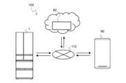
- Fig. 1 is a block diagram showing an example of a configuration of a refrigerated material management system including a refrigerator according to the first embodiment.
- the refrigerated material management system 100 has a refrigerator 1, an external device 80, and an information processing terminal 90.
- the refrigerator 1, the external device 80, and the information processing terminal 90 are each connected to other devices for communication via a network 110.
- the network 110 is a wide area network such as the Internet.
- the external device 80 is, for example, a computer that provides cloud computing services.
- the information processing terminal 90 is a terminal carried by the user of the refrigerator 1. In the first embodiment, the case where there is one information processing terminal 90 is described, but there may be multiple information processing terminals 90. Also, the case where there is one external device 80 is described, but there may be multiple external devices 80.
- FIG. 2 is a front view of the refrigerator shown in Fig. 1.
- Fig. 3 is a front view of the refrigerator shown in Fig. 2 with the door omitted.
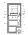
- Fig. 4 is a schematic cross-sectional view of the refrigerator shown in Fig. 3 taken along line A-A.
- refrigerator 1 has an insulated box 2, which is the main body of the refrigerator, with an open front and a storage space 6 formed inside.
- Insulated box 2 has a steel outer box 3, a resin inner box 4, and insulating material 5 filled in the space between outer box 3 and inner box 4.
- storage space 6 is formed in which food or other items to be cooled are stored.
- Storage space 6 is divided by a number of partitions 7 to 10.
- refrigerator 1 has multiple storage compartments, including refrigerator compartment 11, ice-making compartment 12, switchable compartment 13, vegetable compartment 14, and freezer compartment 15.
- Refrigerator compartment 11 is located on the top level. Ice-making compartment 12 and switchable compartment 13 are located below refrigerator compartment 11. Ice-making compartment 12 and switchable compartment 13 are adjacently arranged in parallel along the horizontal plane.
- Vegetable compartment 14 is located below switchable compartment 13 and ice-making compartment 12.
- Freezer compartment 15 is located below vegetable compartment 14.
- the switchable compartment 13 is a storage compartment that can be switched to multiple set temperature zones.
- the multiple set temperature zones are, for example, a freezing temperature zone, a soft freezing temperature zone, a chilled temperature zone, a refrigerated temperature zone, and a vegetable storage temperature zone.
- the freezing temperature zone is, for example, about -18°C.
- the soft freezing temperature zone is, for example, about -7°C, specifically, in the range of -10°C to -4°C.
- the chilled temperature zone is, for example, about 0°C, specifically, in the range of -3°C to 0°C.
- the refrigerated temperature zone is, for example, about 3°C.
- the vegetable storage temperature zone is, for example, about 6°C.
- the ice making compartment 12, the switchable compartment 13, the vegetable compartment 14, and the freezer compartment 15 each have a pull-out storage case (not shown) that the user can pull out to the front side of the refrigerator 1.
- a door 26 is provided in front of the ice making compartment 12.
- a door 27 is provided in front of the switchable compartment 13.
- a door 28 is provided in front of the vegetable compartment 14.
- a door 29 is provided in front of the freezer compartment 15.
- a storage case (not shown) capable of storing items to be cooled inside is stored in the vegetable compartment 14 and can be pulled out freely.
- the storage case (not shown) is supported by a frame fixed to the door 28, and slides back and forth in conjunction with the opening and closing of the door 28.
- a storage case (not shown) capable of storing items to be cooled such as food inside is also stored in the freezer compartment 15 and can be pulled out freely.
- each storage compartment is provided with one storage case. Two or more storage cases may be provided in one storage compartment if convenience such as storage capacity and ease of organization is improved, taking into consideration the overall capacity of the refrigerator 1.
- refrigerator 1 The type and number of storage compartments in refrigerator 1 are not limited to the configuration shown in Figs. 1 to 4. Also, refrigerator 1 shown in Figs. 1 to 4 is a bottom freezer type refrigerator in which freezer compartment 15 is located on the lowest level, but refrigerator 1 is not limited to a bottom freezer type refrigerator. For example, refrigerator 1 may be a top freezer type refrigerator in which freezer compartment 15 is located on the highest level. In this embodiment 1, a bottom freezer type refrigerator will be described as an example of refrigerator 1.
- the refrigerator compartment doors 20 and 21 are attached to the outer box 3 via hinges 76 and are provided to open and close the opening 11c of the refrigerator compartment 11.
- the refrigerator compartment doors 20 and 21 of the refrigerator 1 in this embodiment 1 are of a double door type.
- the refrigerator compartment door 20 has a built-in operation panel 23.
- the operation panel 23 includes an operation unit 24 for adjusting the set temperature of each storage compartment, and a display unit 25 for displaying the temperature of each storage compartment and inventory information in the refrigerator.
- the operation unit 24 is composed of, for example, an operation switch.
- the display unit 25 is composed of, for example, a liquid crystal display.
- the operation panel 23 may be a touch panel in which the display unit 25 and the operation unit 24 are integrated with each other, with the operation unit 24 superimposed on the display unit 25.
- the refrigerator compartment door 20 has a built-in wireless communication device 71 that connects to an external device 80 via a network.
- the wireless communication device 71 is connected to the operation panel 23 via a signal line 73.
- a control device 70 is provided at the top of the back of the refrigerator 1, and the operation panel 23 is connected to the control device 70 via a signal line 74.
- the wireless communication device 71 is connected to the control device 70 via the signal line 73, the operation panel 23, and the signal line 74.
- the location where the wireless communication device 71 is installed is not limited to inside the front side of the refrigerator 1. If the wireless communication device 71 is installed inside the refrigerator 1, it may be installed, for example, inside the side wall of the refrigeration compartment 11 or near the control device 70 inside the rear side of the refrigerator 1. The location where the wireless communication device 71 is installed is not limited to inside the refrigerator 1, and it may be on the top surface of the outer box 3 of the refrigerator 1. The wireless communication device 71 may also be directly connected to the control device 70 via a signal line without going through the operation panel 23.
- a control device 70 that controls the operation of the refrigerator 1 is provided at the upper rear of the refrigerator 1.
- a cooling device 30 that generates cold air an air duct 39 that supplies cold air to each of the storage compartments, ie, the refrigerator compartment 11, the low temperature compartment 51, and the chilled compartment 50 shown in FIG. 3, and a fan grill 43 are provided.
- the cooling device 30 has a compressor 31, a cooler 32 that functions as an evaporator, a blower fan 33, an air passage 34, and a damper 36.
- the air duct 39 is connected to the air passage 34 via the damper 36.
- the air passage 34 is formed by an inner partition air passage 34a formed in the partition 7 and an inner fan grill air passage 34b formed in the fan grill 43.
- the damper 36 adjusts the amount of cold air supplied to the refrigerator compartment 11, the low temperature compartment 51, and the chilled compartment 50.
- the fan grill 43 is a component located at the rear of the ice-making compartment 12, the switchable compartment 13, and the vegetable compartment 14.
- the cooler compartment 35 and the air passage 34 are formed by the fan grill 43 and the insulation material 5 at the rear of the refrigerator 1.
- An air duct 39 is provided above the fan grill 43 via the partition 7. As shown in FIG. 4, a part of the inner box 4 forms the rear surface 11a of the refrigerator compartment 11 above the shelf 41, and forms the rear surface 11b of the chilled compartment 50 between the shelf 41 and the partition 7.
- the air duct 39 is provided at the rear surface 11a of the refrigerator compartment 11 and the rear surface 11b of the chilled compartment 50.
- the cooler 32 and the blower fan 33 are provided inside the cooler chamber 35.
- the expansion device (not shown) is, for example, a capillary tube.
- the cold air generated by the refrigeration cycle circuit including the compressor 31 and the cooler 32 is sent to the air duct 34 by the blower fan 33.
- a portion of the cold air sent out by the blower fan 33 is supplied from the air duct 34 to the switching chamber 13, the ice making chamber 12, and the freezer chamber 15.
- the remaining cold air is supplied from the air duct 34 to the refrigerator chamber 11, the low temperature chamber 51, and the chilled chamber 50 via the damper 36 and the blower duct 39.
- the vegetable chamber 14 is cooled by the return cold air from the refrigerator chamber 11 being supplied through a return air duct (not shown) for the refrigerator chamber.
- a temperature sensor 37 that measures the ambient temperature of the refrigerator compartment 11 is provided on the rear surface 11a of the refrigerator compartment 11.
- a temperature sensor 38 is provided on the rear surface 11b of the chilled compartment 50 near the air outlet 60b through which cold air flows from the air duct 39 into the chilled compartment 50.
- the temperature sensor 38 measures the ambient temperature near the air outlet 60b.
- the ambient temperature measured by the temperature sensor 38 is referenced by the control device 70 when adjusting the temperature of the cold air flowing into the chilled compartment 50 from the air outlet 60b.
- the temperature sensors 37 and 38 are composed of thermistors, for example.
- multiple shelves 40a-40d and 41 are installed inside the refrigerator compartment 11.
- the shelves 40a-40d and 41 are installed at intervals so as to divide the space inside the refrigerator compartment 11 in the direction perpendicular to the installation surface of the refrigerator 1 (Z axis).
- a low-temperature compartment 51 is formed between shelf 40d and shelf 41, and a chilled compartment 50 is formed between shelf 41 and partition 7.
- the shelves 40a-40d and 41 are made of, for example, a translucent material.
- the low-temperature chamber 51 is a storage space 6 that is set to a supercooling temperature zone, which is a temperature zone that allows the objects to be stored without freezing them, but is below the freezing point.
- the chilled chamber 50 is a storage space 6 that stores objects to be cooled in the chilled temperature zone.
- the chilled chamber 50 houses a case 45.
- the case 45 is, for example, box-shaped with an open top.
- the case 45 is a translucent member.
- a handle 45a is provided on the front side of the case 45.
- the case 45 is a container that a user can grab by the handle 45a and take out or put into the chilled chamber 50, so that the user can easily store objects to be cooled in the chilled chamber 50 or take out the objects to be cooled from the chilled chamber 50.
- the case 45 is called a chilled case.
- case 45 is, for example, 588 mm in width (X-axis direction), 316 mm in depth (Y-axis direction), and 54 mm in height on the front side (Z-axis direction).
- the top surface of case 45 is separated from refrigeration compartment 11 by shelf 41. Therefore, even if the ambient temperature of refrigeration compartment 11 is kept in the refrigeration temperature zone, the ambient temperature inside case 45 is kept in the chilled temperature zone, which is different from the refrigeration temperature zone.
- a door opening/closing detection unit 75 that detects the open/closed state of the refrigerator compartment doors 20 and 21 is provided inside the front side of the partition 7.
- the door opening/closing detection unit 75 is connected to the control device 70 via a signal line (not shown).
- the door opening/closing detection unit 75 transmits an open signal to the control device 70, which is a signal indicating that the doors are open.
- the door opening/closing detection unit 75 transmits a close signal to the control device 70, which is a signal indicating that the doors are closed.
- the door opening/closing detection unit 75 is, for example, a door switch or a reed switch.
- the low temperature compartment 51 and the chilled compartment 50 are provided below the refrigerator compartment 11, but the refrigerator 1 may be configured with only one of the low temperature compartment 51 or the chilled compartment 50.
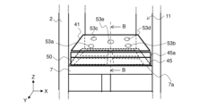
- Figure 5 is an enlarged schematic diagram of the chilled compartment shown in Figures 3 and 4, viewed from the front.
- Figure 5 in order to show the configuration of the infrared sensors 53a to 53e and the partition 7, the shelves other than the bottom shelf 41 among the multiple shelves 40a to 40d and the case 45 are omitted.
- Figure 6 is a schematic diagram showing the state in which a case is stored in the chilled compartment shown in Figure 5.
- Figure 7 is a schematic diagram showing the floor surface of the chilled compartment shown in Figure 5.
- infrared sensors 53a-53e are provided on the underside of shelf 41.
- Infrared sensor 53a is the first sensor.
- Infrared sensor 53b is the second sensor.
- Infrared sensor 53c is the third sensor.
- Infrared sensor 53d is the fourth sensor.
- Infrared sensor 53e is the fifth sensor.
- partition 7 has a plurality of heaters 54a-54d provided on floor surface 7a of refrigerator compartment 11. Heater 54e (not shown) may be provided on floor surface 7a at a position opposite infrared sensor 53e.
- Heater 54a is the first heater.
- Heater 54b is the second heater.
- Heater 54c is the third heater.
- Heater 54d is the fourth heater.
- Heater 54e is the fifth heater.
- Each of the infrared sensors 53a to 53e and the heaters 54a to 54d is connected to the control device 70 via a signal line (not shown).
- a case 45 is installed between the infrared sensors 53a to 53e and the heaters 54a to 54d.
- the floor surface 7a is virtually divided into a plurality of areas 55a to 55e. Area 55a is the first area. Area 55b is the second area. Area 55c is the third area. Area 55d is the fourth area. Area 55e is the fifth area.
- the bottom surface of the case 45 is also virtually divided into areas 55a to 55e.
- Each of the infrared sensors 53a to 53e and each of the areas 55a to 55e are arranged facing each other in a one-to-one relationship.
- the infrared sensors 53a to 53e use infrared rays to detect heat emitted from the object to be measured, and transmit a voltage signal corresponding to the surface temperature of the object to the control device 70.
- the infrared sensors 53a to 53e are described as being thermal sensors, but the infrared sensors 53a to 53e may also be quantum sensors.
- Thermal sensors utilize the Seebeck effect, which is a property that generates an electromotive force between a cold part and a hot part.
- Thermal sensors measure the temperature of an object by detecting the amount of infrared energy emitted from the object.
- Thermal sensors detect the heat quantity of an object as a voltage difference by generating a thermoelectromotive force proportional to the amount of incident infrared energy, and are characterized by their low wavelength dependency, making them suitable for detecting temperature changes of an object over time.
- Infrared sensors 53a to 53e may convert a voltage signal into a temperature value and send it to control device 70.
- Each of the infrared sensors 53a to 53e detects infrared rays emitted from each of the areas 55a to 55e.
- the storage space of the chilled room 50 is divided into a plurality of areas 55a to 55e corresponding to the arrangement of the infrared sensors 53a to 53e, and one infrared sensor is arranged in each area.
- the arrangement of the infrared sensors and the areas is not limited to the configuration shown in Figures 5 and 6.
- Infrared sensors 53a to 53e begin measurement when refrigerator 1 starts operating.
- a user places an object to be cooled in area 55a in the initial stage after refrigerator 1 starts operating and before chilled compartment 50 reaches the chilled temperature zone.
- control device 70 can determine the presence or absence of an object to be cooled and the state of the object to be cooled based on the change over time of the measurement value of infrared sensors 53a to 53e.
- heaters 54a to 54d are provided at positions overlapping areas 55a to 55d, respectively. Also, heaters 54a to 54d partially overlap area 55e, but are provided so as not to overlap areas 55a to 55d other than area 55e. This configuration is not limited, and five heaters may be provided so that temperature control can be performed for each area. Also, one heater may be provided so as to span two or more areas. Furthermore, heaters 54a to 54d may be provided on floor surface 7a.
- the case 45 is also molded from a plastic material such as polystyrene or polypropylene, but is not limited to these materials. However, if the infrared sensors 53a to 53e are provided on the partition 7 side, it is desirable for the case 45 to be molded from a polypropylene material that easily transmits infrared rays emitted from the object to be cooled.
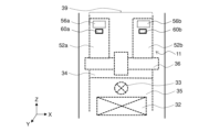
- Figure 8 is a schematic diagram showing the state when each air passage formed in the air duct 39, partition 7, and fan grill 43 provided on the back surface 11a of the refrigerator compartment 11 and the back surface 11b of the chilled compartment 50 shown in Figure 4 is seen from the front.
- Figure 8 the configuration of the low temperature compartment 51 and the chilled compartment 50 in the refrigerator compartment 11 is omitted.
- Figure 9 is a diagram showing the state when a case is stored in the chilled compartment of the refrigerator compartment shown in Figure 8.
- the shelf 41, the side wall of the chilled compartment 50, and the partition 7 are omitted.
- the rear surface 11a of the refrigerator compartment 11 and the rear surface 11b of the chilled compartment 50 are provided with an air duct 39 for circulating the cold air cooled by the cooler 32 to the refrigerator compartment 11, the low temperature compartment 51, and the chilled compartment 50.
- the air duct 39 is provided with a pair of outlets 60a and 60b.
- the outlet 60a is the first outlet.
- the outlet 60b is the second outlet and is located to the right of the outlet 60a when looking at the chilled compartment 50 from the front.
- the outlets 60a and 60b are formed in the area 39a of the air duct 39 facing the chilled compartment 50, and are located behind the rear surface of the case 45.
- the control device 70 independently controls the amount of cold air blown out from the outlets 60a and 60b, respectively, to distribute the cold air and to cool the cooled object by specifying the range in which the cooling speed and temperature are controlled depending on the position and temperature state of the cooled object in the case 45.
- the air duct 39 has two air passages 52a and 52b for sending cool air to the chilled compartment 50.
- Air passage 52a is the first air passage.
- Air passage 52b is the second air passage and is located to the right of air passage 52a when looking at the refrigerator 1 from the front.
- a damper 36 is provided between air passage 34 and air passage 52a, and between air passage 34 and air passage 52b, for controlling the distribution of cool air to the chilled compartment 50.
- Air passage 34 is connected to the cooler compartment 35 on the side opposite damper 36.
- Damper 36 is provided with a first lid portion 56a and a second lid portion 56b corresponding to air passages 52a and 52b. Lid portions 56a and 56b are controlled to open and close individually. By closing the lid 56a and opening only the right lid 56b, the cold air from the cooler chamber 35 flows only through the air passage 52b, and the cold air is concentrated on the right side inside the case 45.
- the refrigerator 1 can blow the cold air generated by the cooler 32 into each storage chamber by forming a flow with the blower fan 33, controlling the opening and closing of the damper and the lid provided corresponding to each storage chamber, and stopping or letting the flow of the cold air flow.
- the lids 56a and 56b are provided above the air outlets 60a and 60b, respectively, but the configuration is not limited to the above, and the lids 56a and 56b may be provided inside the damper 36 shown in FIG. 8.
- an air passage for the refrigerator compartment is provided above air passages 52a and 52b, but this is omitted from Figures 8 and 9.
- FIG. 10 is a schematic diagram showing the positional relationship between the case shown in FIG. 6 and multiple heaters.
- heaters 54a to 54d are arranged inside partition 7 corresponding to the positions of detection areas 57a to 57d of infrared sensors 53a to 53d.
- Heater 54e (not shown) may be arranged corresponding to the position of detection area 57e of infrared sensor 53e.
- Partition 7 forms the floor surface of chilled compartment 50 and serves to separate refrigerator compartment 11 from ice-making compartment 12 and switchable compartment 13.
- Heaters 54a to 54d are composed of a heating wire such as a nichrome wire and a metal part attached to the heating wire. Heaters 54a to 54d can set the temperature of the floor surface of chilled compartment 50 to one of multiple temperatures by changing the current value of the heating wire.
- FIG. 11 is a schematic cross-sectional view of the chilled compartment taken along line B-B in FIG. 6.
- FIG. 11 shows a case where no object to be cooled is stored in case 45 of chilled compartment 50.
- FIG. 12 is another schematic cross-sectional view of the chilled compartment taken along line B-B in FIG. 6.
- FIG. 12 shows a case where object to be cooled 65 is stored in case 45 of chilled compartment 50.
- FIG. 13 is a schematic cross-sectional view showing a detailed configuration of the cross-sectional structure shown in FIG. 11.
- the case of infrared sensor 53e will be mainly explained.
- the bottom surface 41a of the shelf 41 has an opening corresponding to each of the infrared sensors 53a to 53e.
- the infrared sensor 53a is provided so that the lens 58 of the infrared sensor 53a fits into the opening.
- the lens 58 of the infrared sensor 53e faces downward in the opening to measure the temperature of the case 45 or the object to be cooled by infrared rays.
- the diameter of the lens 58 of the infrared sensors 53a to 53e is about 10 mm.
- the diameter of the opening is equal to or larger than the diameter of the lens 58.
- the surface of the lens 58 is located at the same height as the bottom surface 41a of the shelf 41 or above the bottom surface 41a. This arrangement prevents the lens 58 from coming into contact with the object to be cooled stored in the case 45 when the user pulls out the case 45.
- infrared sensors 53a to 53e each have four terminals VDD, GND, VTamb and VTobj.
- VDD is a terminal to which the power line is connected, and a 5V power supply is input from the control device 70.
- GND is a terminal to which the GND wiring is connected, and a reference potential (0V) is input from the control device 70.
- VTamb is a terminal to which the first output wiring is connected, and a voltage corresponding to the temperature of the atmosphere surrounding infrared sensors 53a to 53e is output.
- VTobj is a terminal to which the second output wiring is connected, and a voltage corresponding to the temperature of the cooled object or the temperature of case 45 measured by infrared sensors 53a to 53e, respectively, is output.
- the power line, GND wiring, first output wiring, and second output wiring extend from inside the shelf 41 to the rear or left and right sides of the shelf 41, are pulled into the inside of the insulated box 2 from the rear or left and right sides of the shelf 41, are routed inside the insulated box 2 upward along the back surface 11a of the refrigerator compartment 11, and are connected to the control device 70.
- the shelf 41 in which the infrared sensors 53a to 53e are installed is designed to have a vertical width of about 10 mm.
- the shelf 41 may have a heat insulating material such as urethane foam or vacuum insulation material on the inside.
- the shelf 41 may have a configuration with an air layer inside. In this case, the air layer suppresses the transfer of heat between the refrigerator compartment 11 and the chilled compartment 50.
- the shelf 41 is constructed by assembling a part that constitutes the upper surface and a part that constitutes the lower surface 41a.
- Infrared sensors 53a to 53e detect infrared rays emitted from the object to be cooled or case 45 in the corresponding detection areas 57a to 57e.
- detection areas 57a to 57e are regions where the bottom surface of case 45 overlaps with lenses 58 of infrared sensors 53a to 53e in the vertical direction (Z axis) when case 45 is pushed all the way into refrigerator compartment 11 (when case 45 is stored in chilled compartment 50). This configuration prevents infrared sensors 53a to 53e from detecting infrared rays from objects to be cooled placed in other areas.
- the structure of the lens 58 and the area of the detection areas 57a to 57e are not limited to this configuration.
- the detection areas 57a to 57e may be the area where a truncated cone extending vertically downward from the outer periphery of the lens 58 intersects with the bottom surface of the case 45.
- the detection areas 57a to 57e overlap with the lenses 58 of the infrared sensors 53a to 53e in the vertical direction (Z axis) in the case 45 and are areas extending concentrically including the lenses 58.
- the area of the detection areas 57a to 57e is larger than when only infrared rays emitted from an object directly below the lens 58 are detected.
- Detection areas 57a to 57e are located in the center of the corresponding areas 55a to 55e.
- the number of infrared sensors is five, and the number of areas of the case 45 is five.
- the size of the areas is determined based on the smallest container, such as a tray, that is commercially available. For example, in a food store, the smallest container among trays that store ingredients such as meat or fish is a container that is 80 mm long and 80 mm wide.
- the size of the areas 55a to 55e is determined so that it is detected in one of the areas 55a to 55e.
- the area 55a is provided on the left side of the front of the chilled compartment 50 (case 45).
- the area 55b is provided on the right side of the front of the chilled compartment 50 (case 45).
- the area 55c is provided on the left side of the rear of the chilled compartment 50 (case 45).
- Area 55d is provided on the right rear side of the chilled compartment 50 (case 45).
- Area 55e is provided in the center of the chilled compartment 50 (case 45) in the front-to-back direction (Y-axis direction) and left-to-right direction (X-axis direction), between areas 55a and 55d and between areas 55b and 55c.
- the positions and number of the infrared sensors 53a to 53e provided on the shelf 41 and the positions and number of the areas 55a to 55e facing the infrared sensors 53a to 53e are not limited to the configurations described with reference to Figures 5 to 7, and can be changed as appropriate.
- the positions and number of the heaters 54a to 54d provided corresponding to the areas 55a to 55d are not limited to the positions and numbers described with reference to Figure 10.
- FIG. 14 is a block diagram showing an example configuration of the control device, external device, and information processing terminal of the cooled object management system according to embodiment 1.
- the control device 70 is configured, for example, by a calculation device such as a microcomputer or a CPU (Central Processing Unit), and software executed by the calculation device.
- the hardware of the control device 70 may be configured by a dedicated circuit that realizes the functions described below. An example hardware configuration will be described later.
- the control device 70 receives measurement values from the infrared sensors 53a-53e and the temperature sensors 37 and 38, and operation signals are input from the operation unit 24 of the operation panel 23. Based on the measurement values of the infrared sensors 53a-53e and the temperature sensors 37 and 38, the control device 70 controls the operating frequency of the compressor 31, the rotation speed of the blower fan 33, and the opening degree of the damper 36 so as to keep the temperature of each storage compartment in the refrigerator 1 within the set temperature range for each storage compartment.
- the refrigerator compartment 11 is set to the refrigeration temperature range, the chilled compartment 50 to the chilled temperature range, the freezer compartment 15 to the freezer temperature range, and the vegetable compartment 14 to the vegetable storage temperature range.
- the control device 70 causes the display unit 25 of the operation panel 23 to display information regarding the temperature of each storage compartment, inventory information within the refrigerator, and the like.
- the control device 70 determines that the air temperature in the chilled compartment 50 is outside the chilled temperature zone, and controls the damper 36 to an open state. As a result, cold air is supplied to the chilled compartment 50 from the air outlet 60a or 60b, and the temperature in the chilled compartment 50 drops. The control device 70 also supplies the return cold air of the refrigerator compartment 11 to the chilled compartment 50. This raises the temperature in the chilled compartment 50. In this way, the control device 70 controls the ambient temperature in the chilled compartment 50 to be within the chilled temperature zone.
- the control device 70 determines that the damper 36 is not operating normally, and notifies the user of the abnormality in the damper 36 via the operation panel 23 or the information processing terminal 90.
- the control device 70 switches the heaters 54a to 54d between on and off states or changes the power supply rate based on the determination of the presence or absence of an object to be cooled and the measurement of the temperature of the object to be cooled. A specific description will be given below.
- the control device 70 determines whether the measured values of the infrared sensors 53a to 53e belong to the chilled temperature zone. If there is a high-temperature area among the areas 55a to 55e where the measured value of the infrared sensor is higher than the chilled temperature zone, the control device 70 controls the lid 56a or 56b. This cools the high-temperature area with cold air, thereby keeping the temperature of the object to be cooled placed in the high-temperature area within the chilled temperature zone.
- the control device 70 controls the heater provided in the low-temperature area. This. By raising the temperature of the low-temperature area, the temperature of the object to be cooled placed in the low-temperature area is kept within the chilled temperature zone.
- control device 70 determines that an object to be cooled is placed in one of areas 55a-55e where a temperature different from the temperature of case 45 is measured. For example, control device 70 operates heaters 54a-54d when refrigerator compartment doors 20 and 21 are opened and closed, and determines the presence or absence of an object to be cooled for each of the multiple areas based on the difference between the change over time in temperature of case 45 due to heating by heaters 54a-54d and the change over time in temperature of the object to be cooled.
- the control device 70 determines the ratio of areas determined to have cooled materials to the total of areas 55a-55e as the storage rate of the storage room from the determination result of the presence or absence of cooled materials in each of areas 55a-55e.
- the control device 70 transmits area information including information on the presence or absence of cooled materials in each of areas 55a-55e and the storage rate of the storage room to the information processing terminal 90 via the wireless communication device 71 and network 110.
- the control device 70 may transmit the area information to the external device 80 via the wireless communication device 71 and network 110.
- Figure 15 is a schematic diagram of a case where the case is pushed all the way into the chilled compartment and no object to be cooled is stored therein.
- infrared sensors 53a-53e detect the temperature of case 45 within detection areas 57a-57e, so the control device 70 determines that no object to be cooled 65 is stored in case 45, and calculates a storage rate of 0%.
- FIG. 16 is a schematic diagram of a case where the chilled compartment is closed and objects to be cooled are stored in all areas.
- FIG. 17 is a schematic diagram of a case where the chilled compartment is closed and objects to be cooled are stored in some of the multiple areas.
- objects to be cooled are placed in all detection areas 57a to 57e, and all infrared sensors 53a to 53e measure the temperature of the objects to be cooled, so the control device 70 determines that objects to be cooled are stored in all areas 55a to 55e, and calculates a storage rate of 100%.
- FIG. 17 is a schematic diagram of a case where the chilled compartment is closed and objects to be cooled are stored in some of the multiple areas. In the case of FIG.
- the control device 70 transmits information indicating that the storage rate of the cooled object is reduced as the state of the cooled object to the information processing terminal 90 via the wireless communication device 71.
- the storage rate of the cooled object is reduced, for example, when the storage rate is 20% or less.
- control device 70 predicts the time required to defrost the object from a table showing the relationship between temperature and time, and estimates the time when defrosting will be completed.
- the controller 70 controls the heaters 54a to 54d to operate and heat the case 45 when the user closes the door. This allows the controller 70 to correctly estimate the amount of food inventory from the difference in the change over time in the temperature rise of areas 55a to 55e. This control is effective even if items to be cooled at a temperature similar to that of the chilled temperature zone are stored in the chilled compartment 50.
- control device 70 determines that the temperature of the object to be cooled has stabilized within the set temperature range based on the temperature information measured by each of the infrared sensors 53a-53e, there is no need to open or close the damper 36 or energize the heaters 54a-54d unless the user issues an instruction from the information processing terminal 90 to switch to the defrosting mode or quick-cooling mode. Therefore, the control device 70 switches the damper 36 to a closed state and stops the supply of power to the heaters 54a-54d. This automatically switches to an energy-saving mode that reduces the power consumption of the heaters 54a-54d and the cooling device 30.
- FIG. 18 is a hardware configuration diagram showing an example of the configuration of the control device shown in FIG. 14.
- the control device 70 shown in FIG. 14 is configured by a processing circuit 150 shown in FIG. 18.
- the processing circuit 150 corresponds to, for example, a single circuit, a composite circuit, a programmed processor, a parallel programmed processor, an ASIC (Application Specific Integrated Circuit), an FPGA (Field-Programmable Gate Array), or a combination of these.
- FIG. 19 is a hardware configuration diagram showing another example of the configuration of the control device shown in FIG. 14.
- the control device 70 is composed of a processor 151 such as a CPU and memory 152, as shown in FIG. 19.
- the various functions of the control device 70 are realized by the processor 151 and memory 152.
- FIG. 19 shows that the processor 151 and memory 152 are communicatively connected to each other via a bus 153.
- the various functions of the control device 70 are executed by software, the various functions of the control device 70 are realized by software, firmware, or a combination of software and firmware.
- the software and firmware are written as programs and stored in the memory 152.
- the processor 151 realizes the various functions of the control device 70 by reading and executing the programs stored in the memory 152.
- non-volatile semiconductor memory such as ROM (Read Only Memory), flash memory, EPROM (Erasable and Programmable ROM), and EEPROM (Electrically Erasable and Programmable ROM) may be used as memory 152.
- Volatile semiconductor memory such as RAM (Random Access Memory) may also be used as memory 152.
- removable recording media such as magnetic disks, flexible disks, optical disks, CDs (Compact Discs), MDs (Mini Discs), and DVDs (Digital Versatile Discs) may also be used as memory 152.
- the refrigerator 1 is described as having a wireless communication device 71, but the control device 70 may also have a communication function executed by the wireless communication device 71.
- the external device 80 is, for example, an information processing device such as a server or a workstation.
- the external device 80 has a memory unit 81 and a control unit 82.
- the control unit 82 has an estimation unit 83 and a learning unit 84.
- the memory unit 81 is, for example, a HDD (Hard Disk Drive) or an SSD (Solid State Drive).
- the hardware of the control unit 82 is, for example, similar to the configuration described with reference to FIG. 19.
- the memory unit 81 stores various data received from the control device 70 of the refrigerator 1.
- the various data received from the control device 70 are, for example, time series data of the measurement values of each of the infrared sensors 53a to 53e and time series data of the storage rate of the chilled compartment 50. This time series data may include information on the time of day and the day of the week.
- the memory unit 81 stores the learning model.
- the learning unit 84 takes as input the time series data of the measured values of each of the infrared sensors 53a to 53e and constructs a learning model that outputs the time at which the cooled items converge to the set temperature range.
- the learning unit 84 also takes as input the time series data of the storage rate of the chilled compartment 50 and constructs a learning model that stores the consumption tendency of the cooled items as an output.
- the consumption tendency of the cooled items is, for example, the storage rate falling below a predetermined threshold value in a predetermined period of time. The period is, for example, 3 to 7 days.
- the threshold value is, for example, 20%.
- the learning unit 84 constructs the learning model using a learning algorithm such as supervised learning, reinforcement learning, or unsupervised learning.
- the estimation unit 83 estimates the temperature changes in areas 55a to 55e based on time series data of the measurement values of each of the infrared sensors 53a to 53e.
- the estimation unit 83 estimates the user's consumption of cooled items based on time series data of the storage rate of the chilled compartment 50.
- the estimation unit 83 may make estimations using a learning model stored in the memory unit 81.
- the estimation unit 83 receives the storage rate and the measurement values of the multiple infrared sensors from the control device 70, it may use this information and the learning model to make a temperature prediction or inventory prediction of the cooled items and estimate an appropriate operating mode or inventory information to suggest to the user.
- the information processing terminal 90 is, for example, a portable information processing device such as a smartphone or a PDA (Personal Digital Assistant).
- the information processing terminal 90 has a storage unit 91, a control unit 92, a display unit 93, and an operation unit 94.
- the storage unit 91 is, for example, an SSD.
- the display unit 93 is, for example, a liquid crystal display.
- the operation unit 94 is, for example, a touch panel.
- the hardware of the control unit 92 is similar to the configuration described with reference to FIG. 18 or FIG. 19, for example.
- the memory unit 91 stores information received from the refrigerator 1 and information received from the external device 80.
- the control unit 92 displays the information received from the refrigerator 1 and information received from the external device 80 on the display unit. For example, when the control unit 92 receives area information from the refrigerator 1, it displays on the display unit 93 an image indicating which area 55 of the chilled compartment 50 the item to be cooled is stored in.
- the control unit 92 transmits the instruction information to the control device 70 of the refrigerator 1 or the control unit 82 of the external device 80.
- Figs. 20 and 21 are flowcharts showing an example of the operation procedure of the refrigerator according to the first embodiment.
- Fig. 22 is a graph showing the infrared sensor measurement value and the heater on and off states in a time series in the temperature control performed by the refrigerator according to the first embodiment.
- Fig. 23 is a sequence diagram showing a part of the operation procedure of the refrigerated material management system according to the first embodiment. The sequence diagram shown in Fig. 23 is intended to show the timing of sending and receiving information between devices, and does not include detailed content of the processing performed by each device.
- a case where a case 45 is stored in the chilled compartment 50 will be described.
- the infrared sensors 53a-53e measure the temperatures of the multiple areas 55a-55e in chronological order and transmit the measured temperatures of the multiple areas 55a-55e to the control device 70.
- step S1 the control device 70 determines whether the refrigerator compartment doors 20 and 21 have been opened or closed. Specifically, the control device 70 determines whether the refrigerator compartment doors 20 and 21 have been opened or closed as follows. When the user opens the refrigerator compartment doors 20 and 21, the door opening/closing detection unit 75 sends an open signal to the control device 70. Next, the user pulls out the case 45 to open the chilled compartment 50 and places the item to be cooled in the case 45. After that, the user closes the chilled compartment 50 and closes the refrigerator compartment doors 20 and 21. When the user closes the refrigerator compartment doors 20 and 21, the door opening/closing detection unit 75 sends a close signal to the control device 70. When the control device 70 receives an open signal from the door opening/closing detection unit 75 and then receives a close signal from the door opening/closing detection unit 75, it determines that the refrigerator compartment doors 20 and 21 have been opened or closed.
- step S1 If the refrigerator doors 20 and 21 are not opened or closed (step S1: No), the control device 70 repeats the judgment process of step S1. On the other hand, if the control device 70 judges that the refrigerator doors 20 and 21 are opened or closed (step S1: Yes), it operates the heaters 54a to 54d (step S2). Next, the control device 70 acquires the measurement values of the infrared sensors 53a to 53e to judge whether or not an object to be cooled is placed in each of the areas 55a to 55e (step S3). After acquiring the measurement values from each of the infrared sensors 53a to 53e, the control device 70 judges whether or not an object to be cooled is placed in each of the areas 55a to 55e based on the temperature information of each of the areas 55a to 55e.
- control device 70 determines whether or not there is an object to be cooled in each of areas 55a to 55e in the processing of steps S2 and 3.
- the temperature of the object to be cooled belongs to the chilled temperature zone, which is the set temperature zone of case 45.
- the temperatures of not only case 45, but also floor surface 7a and ceiling surface of chilled compartment 50 belong to the chilled temperature zone. In this state, it is difficult for control device 70 to determine whether or not there is an object to be cooled in area 55a from the measurement value of infrared sensor 53a.
- the control device 70 operates the heaters 54a to 54d to raise the temperature of the case 45, for example, when the refrigerator doors 20 and 21 are opened or closed.
- the heaters 54a to 54d are operated for a period of time ranging from several tens of seconds to several minutes.
- the object to be cooled itself has a heat capacity, so the temperature of the object to be cooled is less likely to rise when heated by the heaters 54a to 54d than the temperature of the case 45 alone.
- the temperature of the case 45 alone is more likely to rise due to heating by the heaters 54a to 54d.
- the heater 54a operates, a difference occurs in the temperature measured by the infrared sensor 53a between the case where the object to be cooled is placed on the area 55a and the case where the object to be cooled is not placed on the area 55a.
- the control device 70 stores in advance a reference temperature T0, which is a reference value of the temperature of each of the areas 55a to 55e at a predetermined time tref from the start of heater operation when each of the heaters 54a to 54d is operated when no object to be cooled is stored in the case 45.
- a reference temperature T0 is a reference value of the temperature of each of the areas 55a to 55e at a predetermined time tref from the start of heater operation when each of the heaters 54a to 54d is operated when no object to be cooled is stored in the case 45.
- the reference temperature T0 of the areas 55a to 55e is the same, but the reference temperature T0 may be different for each of the areas 55a to 55e.
- An example of the reference temperature T0 will be described with reference to FIG. 22.
- the set temperature Tset shown on the vertical axis of FIG. 22 indicates the center of the chilled temperature zone.
- the reference temperature T0 is the temperature of each of the areas 55a to 55e where no object to be cooled is stored when the heaters 54a to 54d are turned on from time t1 to time t2.
- tref t2-t1.
- the control device 70 operates each of the heaters 54a to 54d for a time tref from time t1, obtains the respective measured values from the infrared sensors 53a to 53e, and compares the temperatures Ta to Te of the areas 55a to 55e at time t2 with the reference temperature T0. If any of the temperatures Ta to Te is lower than the reference temperature T0 as a result of the comparison, the control device 70 determines that an object to be cooled is placed in the area with a temperature lower than the reference temperature T0. On the other hand, if any of the temperatures Ta to Te is equal to the reference temperature T0 as a result of the comparison, the control device 70 determines that no object to be cooled is placed in the area with a temperature equal to the reference temperature T0. In FIG.
- the graph ga2 shows the change over time in the temperature of the area where the object to be cooled is placed. Note that a judgment threshold value for judging whether or not the measured value of each of the infrared sensors 53a to 53e is lower than the reference temperature T0 may be determined in advance.
- control device 70 can determine whether or not there is an item to be cooled in each of areas 55a to 55e.
- This determination method is executed when the refrigerator compartment doors 20 and 21 are opened and closed in step S1, so it is effective both when the user places a new item to be cooled at a temperature similar to the chilled temperature range in the case 45 and when the user removes an item to be cooled from the case 45.
- Graph gb0 in FIG. 22 shows the change over time when the temperature of a cooled object newly placed in case 45 is higher than the chilled temperature zone.
- Graph gb0 is at least three times higher than the reference temperature T0 at time t2. If any of temperatures Ta to Te at time t2 is three times higher than the reference temperature T0, the control device 70 determines that a high-temperature cooled object has been placed in an area where the temperature is three times higher than the reference temperature T0.
- the high-temperature threshold which is the criterion for determining whether a cooled object with a temperature higher than the chilled temperature zone has been placed in case 45 for each measurement value of infrared sensors 53a to 53e, is three times higher than the reference temperature T0 as described above, the high-temperature threshold is not limited to three times the reference temperature T0.
- the control device 70 stores a predetermined high-temperature threshold.
- graph gc0 in FIG. 22 shows the change over time when the temperature of a newly stored cooled object in case 45 is lower than the chilled temperature zone.
- Graph gc0 is at least three times lower than the absolute value of reference temperature T0 at time t2. If any of temperatures Ta to Te at time t2 is three times lower than the absolute value of reference temperature T0, the control device 70 determines that a low-temperature cooled object has been placed in an area where the temperature is three times lower than the absolute value of reference temperature T0.
- the low-temperature threshold which is the criterion for determining whether a cooled object with a temperature lower than the chilled temperature zone has been placed in case 45 for each measurement value of infrared sensors 53a to 53e, is three times lower than the absolute value of reference temperature T0
- the low-temperature threshold is not limited to three times the absolute value of reference temperature T0.
- the control device 70 stores a predetermined low-temperature threshold.
- the control device 70 can determine whether or not there is an object to be cooled in each of areas 55a to 55e.
- the control device 70 can determine whether or not there is an object to be cooled based on the difference between the temperature change of the object to be cooled and the temperature change of the floor surface 7a, in the same manner as described above.
- control device 70 determines whether or not there is an object to be cooled in each of areas 55a-55e, and calculates the ratio of areas determined to have an object to be cooled to the total of areas 55a-55e as the storage rate of the object to be cooled in the case 45 (step S4).
- the control device 70 transmits area information, including information on the presence or absence of refrigerated items and storage rate in areas 55a to 55e of the case 45, to the information processing terminal 90 via the wireless communication device 71 and network 110 (step S5, step SD1 shown in FIG. 23).
- step S5 step SD1 shown in FIG. 23.
- the control unit 92 of the information processing terminal 90 receives the first information from the refrigerator 1, it stores the first information in the memory unit 91 and displays the first information on the display unit 93 (step SD5 shown in FIG. 23). Thereafter, when the control unit 92 of the information processing terminal 90 receives new area information from the refrigerator 1, it updates the information stored in the memory unit 91.
- the control device 70 may transmit the area information to the external device 80 via the wireless communication device 71 and the network 110 (step SD2 shown in FIG. 23).
- the operation of the external device 80 in this case will be described later.
- step S6 the control device 70 acquires measurement values from each of the infrared sensors 53a-53e in chronological order, and estimates the state of the objects to be cooled in each of areas 55a-55e (step S6). Specifically, in step S6, the control device 70 monitors the measurement values of areas 55a-55e in which objects to be cooled are placed. In FIG. 22, it is assumed that the measured temperatures are T1-T3 corresponding to times t1-t3 in the monitored areas. Here, a case will be described in which a new object to be cooled has been placed in area 55a by a user, and area 55a is the area to be monitored.
- step S7 the control device 70 determines whether the temperature T3 measured by the infrared sensor 53a at time t3 in the monitored area 55a is higher than the temperature T2 measured by the infrared sensor 53a at time t2. If the result of the determination in step S7 is that the temperature T3 is higher than the temperature T2, the control device 70 determines that a room temperature or high temperature food item has been stored in the case 45 as the item to be cooled, and proceeds to the processing of step S8.
- step S7 determines that the temperature T3 is equal to or lower than the temperature T2
- the control device 70 determines that a frozen food item that needs to be thawed has been stored in the case 45 as the item to be cooled, and proceeds to the processing of step S14.
- step S8 shown in FIG. 21 the control device 70 transmits mode request information to the information processing terminal 90 requesting the selection of the defrost mode (step SD6 shown in FIG. 23).
- the control unit 92 of the information processing terminal 90 receives the mode request information from the refrigerator 1, it causes the display unit 93 to display an image including a message urging the user to select the defrost mode.
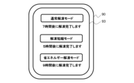
- the energy-saving defrosting mode is a mode in which the refrigerator 1 operates with reduced power consumption until the temperature of the cooled object reaches the chilled temperature range.
- the normal defrosting mode is a mode in which the current operating state of the refrigerator 1 is maintained until the temperature of the cooled object reaches the chilled temperature range.
- the shortened defrosting mode is a mode in which the heater 54a provided in the monitored area 55a is turned on to forcibly defrost the cooled object, shortening the defrosting time compared to the normal defrosting mode and the energy-saving defrosting mode.
- the user selects the normal thawing mode. If the user is not in a hurry to thaw the cooled items and wants to save on power consumption, the user selects the energy-saving thawing mode. If the user wants to quickly thaw the cooled items, the user selects the accelerated thawing mode.
- the user operates the operation unit 94 of the information processing terminal 90 to input an instruction to select one of the three thawing modes.
- the control unit 92 sends information about the thawing mode selected by the user to the refrigerator 1 (step SD7 shown in Figure 23).
- step S8 shown in FIG. 21 the control device 70 determines whether or not the defrosting shortening mode has been selected. If the result of the determination in step S8 is that the defrosting shortening mode has not been selected (step S8: No), the control device 70 proceeds to processing in step S10. In other words, if the normal defrosting mode or the energy-saving defrosting mode has been selected, the control device 70 proceeds to processing in step S10.
- step S10 when the normal thawing mode is selected, the control device 70 predicts the time required to thaw the object from a table showing the relationship between temperature and time, and estimates the time when thawing will be completed.
- the time when thawing will be completed is the time when the surface temperature of the object reaches the chilled temperature range, for example, the time when the surface temperature of the object reaches -3°C.
- the control device 70 transmits the estimated thawing completion time, which is the estimated time, to the information processing terminal 90 (step S10).
- graph gc2 is a graph showing the change in temperature of the object when the normal thawing mode is selected.
- the estimated thawing completion time is t8.
- the control unit 92 of the information processing terminal 90 causes the display unit 93 to display the estimated thawing completion time t8 received from the refrigerator 1.
- step S10 when the energy-saving thawing mode is selected, the control device 70 predicts the time required to thaw the object from a table showing the relationship between temperature and time, and estimates the time when thawing will be completed. The control device 70 then transmits the estimated thawing completion time, which is the estimated time, to the information processing terminal 90 (step S10).
- graph gc3 is a graph showing the change in temperature of the object to be cooled when the energy-saving thawing mode is selected.
- the estimated thawing completion time is t9.
- the control unit 92 of the information processing terminal 90 causes the display unit 93 to display the estimated thawing completion time t9 received from the refrigerator 1.
- control device 70 acquires temperature information of the monitored area 55a from the infrared sensor 53a in chronological order, and repeats the processes of steps S10 to S12 until the temperature of the area 55a falls within the chilled temperature range (step S12: Yes).
- step S8 determines that the defrosting shortening mode has been selected
- the control device 70 operates the heater 54a in the area 55a being monitored (step S9). This shortens the defrosting time of the cooled object.
- step S10 if the defrosting shortening mode has been selected, the control device 70 predicts the time required to defrost the cooled object from a table showing the relationship between temperature and time, and estimates the time when defrosting will be completed. The control device 70 then transmits the estimated time, which is the estimated time, to the information processing terminal 90 (step S10).
- the graph gc1 shows the change in temperature of the cooled object when the defrosting shortening mode has been selected. In this case, the estimated time of defrosting completion is t6.
- the control unit 92 of the information processing terminal 90 causes the display unit 93 to display the estimated time of defrosting completion t6 received from the refrigerator 1.
- the control device 70 acquires temperature information of the monitored area 55a from the infrared sensor 53a in chronological order, and repeats the processes of steps S10 to S12 until the temperature of the area 55a falls within the chilled temperature range (step S12: Yes).
- the heater 54a heats the cooled object placed in the area 55a from the floor up, so the surface of the cooled object is the last to be thawed, but the control device 70 can estimate the time when thawing will be completed from the chronological data of the output of the heater 54a and the temperature of the surface of the cooled object.
- the control device 70 stops the operation of the heater 54a (step S13).
- the estimated decompression completion time is displayed on the display unit 93 of the information processing terminal 90, so that the user is notified earlier when the shortened decompression mode is executed. Furthermore, since steps S10 to S12 are repeated thereafter, more accurate estimated decompression completion times are successively notified to the user via the information processing terminal 90.
- the estimated decompression completion time when the energy-saving decompression mode is selected is time t9 shown in FIG. 22.
- the estimated decompression completion time when the normal decompression mode is selected is time t8 shown in FIG. 22.
- the estimated decompression completion time when the shortened decompression mode is selected is time t5 shown in FIG. 22, which shows that the decompression time can be shortened compared to times t8 and t9.
- the control device 70 may transmit to the information processing terminal 90 information inquiring whether to switch the state of the object to be cooled and the state of the heater 54a determined based on the measurement value of the infrared sensor 53a corresponding to the area 55a to be monitored. In this case, when the control device 70 receives control information from the information processing terminal 90 to change the conduction rate of the heater 54a, it changes the conduction rate of the heater 54a based on the control information.
- step S7 determines whether or not to select the rapid cooling mode.
- step S14 when the control unit 92 of the information processing terminal 90 receives the mode confirmation request information from the refrigerator 1, it causes the display unit 93 to display an image including a message inquiring the user whether or not to select the rapid cooling mode.
- the control unit 92 transmits the instruction information input by the user to the refrigerator 1 (step SD7 shown in FIG. 23).
- step S14 when the control device 70 receives user instruction information from the information processing terminal 90, it determines whether or not the rapid cooling mode has been selected. If the result of the determination in step S14 is that the rapid cooling mode has not been selected (step S14: No), the control device 70 proceeds to the process of step S16.
- step S16 the control device 70 predicts the time required to cool the object to be cooled from a table showing the relationship between temperature and time, and estimates the time when cooling will be completed.
- the control device 70 then transmits the estimated cooling completion time, which is the estimated time, to the information processing terminal 90 (step S16).
- graph gb2 is a graph showing the change in temperature of the object to be cooled when the rapid cooling mode is not selected.
- the estimated cooling completion time is t7.
- the control unit 92 of the information processing terminal 90 causes the display unit 93 to display the estimated thawing completion time t7 received from the refrigerator 1.
- control device 70 acquires temperature information of the monitored area 55a from the infrared sensor 53a in chronological order, and repeats the processes of steps S16 to S18 until the temperature of the area 55a falls within the chilled temperature range (step S18: Yes).
- step S14 the control device 70 controls the blower fan 33, the damper 36, or the lid portion 56a or 56b to cool the monitored area 55a (step S15).
- the damper 36 is open and the control device 70 controls the lid portions 56a and 56b while maintaining the rotation speed of the blower fan 33.
- air outlets 60a and 60b are provided on the rear surface of the chilled compartment 50.
- the area 55a to be cooled is located in the direction in which cool air is blown out from the air outlet 60a. Therefore, the control device 70 controls the lid 56a of the air outlet 60a to be open and the lid 56b of the air outlet 60b to be closed. This causes cool air to be blown out from the air outlet 60a in the direction of the area 55a.
- control device 70 may operate heater 54c to prevent area 55c from becoming too cold. In this way, control device 70 can cool each of areas 55a to 55e by controlling the open or closed state of lids 56a and 56b and the on or off state of heaters 54a to 54d.
- step S16 the control device 70 predicts the time required to cool the objects to be cooled from a table showing the relationship between temperature and time, and estimates the time when cooling will be completed.
- graph gc1 is a graph showing the change in temperature of the objects to be cooled when the rapid cooling mode is selected.
- the estimated time when cooling will be completed is t5.
- the control device 70 transmits the estimated time when cooling will be completed t5 to the information processing terminal 90 (step S16).
- the control unit 92 of the information processing terminal 90 causes the display unit 93 to display the estimated time when thawing will be completed t5 received from the refrigerator 1.
- the control device 70 acquires temperature information of the monitored area 55a from the infrared sensor 53a in chronological order, and repeats the processes of steps S16 to S18 until the temperature of the monitored area 55a falls within the chilled temperature range (step S18: Yes).
- the control device 70 operates the refrigerator 1 in the normal operation mode (step S19). For example, if the control device 70 has increased the operating frequency of the compressor 31 in step S15, it returns the operating frequency of the compressor 31 to its original value in step S19.
- the control device 70 may operate as follows. When the rapid cooling mode is selected, the object to be cooled is cooled by blowing cold air from the air outlet 60a or 60b into the chilled compartment 50, but the cold air may cool the infrared sensor. If the infrared sensor is cooled by the cold air, the control device 70 may recognize that the object to be cooled has been cooled earlier than it actually is. In this case, the control device 70 may erroneously cancel the rapid cooling mode before the temperature of the object to be cooled reaches the set temperature range.
- the control device 70 controls the damper 36 to stop the supply of cold air from the air outlet 60a or 60b to the chilled compartment 50 at a predetermined cycle. Then, while the supply of cold air is stopped, the control device 70 can more accurately recognize the surface temperature of the object to be cooled from the measurement value of the infrared sensor, and can determine whether to continue the rapid cooling mode.
- control device 70 may transmit time-series data on the temperature in the area being monitored to the external device 80 (step SD2 shown in FIG. 23). The operation of the external device 80 in this case will be described later. Also, if the result of the determination process in steps S12 and S18 shown in FIG. 21 is Yes, the control device 70 may turn off the infrared sensors 53a to 53e that have been kept on since the refrigerator 1 started operating. In this case, the power consumption of the refrigerator 1 can be further reduced.
- FIG. 24 is a schematic diagram showing an example of an image displayed on the display unit of the information processing terminal.
- the control unit 92 causes the display unit 93 to display an image including the message shown in FIG. 23.
- FIG. 25 is a schematic diagram showing another example of an image displayed on the display unit of the information processing terminal.
- the control unit 92 causes the display unit 93 to display the presence or absence of refrigerated items and the storage rate in each of areas 55a to 55e.
- the user can check the food inventory in the chilled compartment 50. This allows the user to determine whether or not more purchases are necessary. If the user determines that more purchases are necessary, the user can operate the operation unit 94 of the information processing terminal 90 to input an instruction to select the button labeled Memo, and add the name of the required food to the memo field. This can prevent users from forgetting to buy food.
- FIG. 26 is a schematic diagram showing another example of an image displayed on the display unit by the information processing terminal.
- the control unit 92 causes the display unit 93 to display the image shown in FIG. 26. It is possible that the object to be cooled newly stored in the case 45 has just been cooked or has just been purchased by the user. If the temperature of the object to be cooled newly stored in the chilled compartment 50 is higher than the chilled temperature range (e.g., 10°C or higher), the control device 70 of the refrigerator 1 suggests to the user, via the information processing terminal 90, that the rapid cooling mode be selected.
- the chilled temperature range e.g. 10°C or higher
- FIG. 27 is a schematic diagram showing another example of an image displayed on the display unit of the information processing terminal.
- the control unit 92 causes the display unit 93 to display information on the presence or absence of cooled items in areas 55a to 55e, and a message inquiring which area to select for the defrosting mode.
- the user can look at the image on the display unit 93 and operate the operation unit 94 of the information processing terminal 90 to select the area in which the cooled items to be defrosted are placed, from among the foods stored in areas 55a to 55e. Even if the case 45 is full of food, the user can specify an area and select the food to be defrosted.
- FIG. 28 is a schematic diagram showing another example of an image displayed on the display unit by the information processing terminal.
- the control device 70 may estimate the thawing completion time for the three thawing modes and notify the information processing terminal 90 of the estimated thawing completion time for each thawing mode.
- the control unit 92 causes the image shown in FIG. 28 to be displayed on the display unit 93. The user can look at the image on the display unit 93 and consider whether or not to shorten the thawing time, taking into account the timing when the user will return home or the timing when the user wants to use the cooled object, and select one of the three thawing modes.
- the refrigerator 1 of the present embodiment 1 has a storage compartment that stores items to be cooled, a cooler 32 that generates cold air, an air duct 39 having an air passage through which the cold air flows from the cooler 32 to the storage compartment, a lid 56a or 56b that is provided on the air duct 39 and adjusts the flow rate of the cold air flowing into the storage compartment, the floor surface of the storage compartment is virtually divided into a number of areas 55a to 55e, a number of heaters 54a to 54d are provided in each of the areas, a number of sensors are provided on the ceiling surface of the storage compartment and each sensor measures the temperature of the items to be cooled placed in the area, and a control device 70.
- the multiple sensors are, for example, infrared sensors 53a to 53e.
- the control device 70 determines whether the measurement values of the multiple sensors belong to the set temperature zone. If there is a high-temperature area among the multiple areas 55a-55e, where the sensor measurement value is higher than the set temperature zone, the control device 70 controls the lid portion 56a or 56b to cool the high-temperature area with cold air, thereby keeping the temperature of the cooled object placed in the high-temperature area within the set temperature zone. If there is a low-temperature area among the multiple areas 55a-55e, where the sensor measurement value is lower than the set temperature zone, the control device 70 controls a heater provided in the low-temperature area to heat the low-temperature area, thereby keeping the temperature of the cooled object placed in the low-temperature area within the set temperature zone.
- the storage chamber is divided into a plurality of areas 55a-55e, and an infrared sensor 53a-53e is provided for each area to measure the temperature of the object to be cooled in each area, and the temperature of the object to be cooled in each area is controlled to be within a set temperature range. Therefore, even if a new object to be cooled at room temperature or freezing temperature is stored in the storage chamber, the object to be cooled can be kept within the set temperature range of the storage chamber while minimizing the impact on other objects to be cooled.
- the user can check the food temperature status in the chilled compartment 50 and the amount of food stored in the case 45 by looking at the display unit 93 of the information processing terminal 90 without having to operate the refrigerator 1.
- the user can operate the information processing terminal 90 to instruct the refrigerator 1 to select the rapid cooling mode or defrosting mode, so the user can select the rapid cooling mode or defrosting mode for the stored items that suits the user's lifestyle.
- refrigerator 1 has infrared sensors 53a-53e that measure the temperature of food in real time, allowing the food temperature to be raised or lowered to the target temperature more quickly than with conventional temperature control based on measuring the temperature of the chilled compartment using a thermistor.
- the refrigerated material management system 100 disclosed herein can detect the presence or absence and temperature of food in a non-contact manner to determine the food's preservation status and cooling status. Furthermore, the refrigerated material management system 100 allows the user to select the food's preservation status, so that even if there are no dividers in the case 45, each of areas 55a to 55e can be individually selected to select thawing or cooling.
- control device 70 has been described as analyzing the time-series temperature data for areas 55a to 55e to determine the state of the cooled object and estimate the completion time of thawing or cooling of the cooled object, but these processes may also be performed by the external device 80.
- control unit 82 of the external device 80 When the control unit 82 of the external device 80 receives information including the measurement values of the multiple infrared sensors 53a-53e from the refrigerator 1 via the network 110, it estimates the state of each of the one or more refrigerated items placed in the storage compartment based on the received multiple measurement values, and transmits the estimation results to the information processing terminal 90 via the network 110.
- control unit 92 of the information processing terminal 90 receives the estimation results from the external device 80 via the network 110, it causes the display unit 93 to display the received information on the estimation results.
- control device 70 may transmit information combining the storage rate and date and time to the external device 80 via the network 110.
- the estimation unit 83 of the external device 80 can use the information combining the storage rate and date and time to infer the user's consumption trends.
- the control device 70 may transmit data including the time series measurement values of each of the infrared sensors 53a to 53e to an external device.
- the control unit 82 of the external device 80 stores the data including the time series measurement values of each of the sensors in the memory unit 91.
- the control unit 82 predicts changes in the temperature of the object to be cooled based on the time series information of the multiple measurement values stored in the memory unit 91, estimates the time when the temperature of the object to be cooled will fall within the set temperature range, and transmits the estimated time as an estimation result to the information processing terminal 90.
- the control device 70 may determine the change in the storage rate over time and transmit the time series data of the storage rate to the external device 80.
- the estimation unit 83 of the external device 80 receives the time series data of the storage rate from the control device 70, it estimates the change in the storage rate based on the received time series data of the storage rate. Then, when the estimation unit 83 estimates that the storage rate will be below a predetermined threshold in a predetermined period of time, it transmits estimation information to the effect that the storage rate will be below the threshold to the information processing terminal 90 as an estimation result.
- An example of notification to the user will be described.
- the external device 80 displays a prediction of when the stored food will be consumed in the form of a graph on the display unit 93 of the information processing terminal 90.
- the memory unit 81 of the external device 80 stores various information received from the control device 70.
- the memory unit 81 stores, for example, information on the temperature of the case 45, the temperature of the object to be cooled, and the storage rate.
- the memory unit 81 may also store other information.
- the memory unit 81 may store operating information including the measurement value of the temperature sensor 38, the operating mode selected by the user, and the outside air temperature.
- the estimation unit 83 of the external device 80 estimates the change in the storage rate for each time period or day of the week based on the time series data of the storage rate received from the refrigerator 1. In this case, it is possible to estimate the consumption tendency based on the user's lifestyle.
- the external device 80 can predict the consumption speed and cycle by creating a stock amount transition forecast line on a graph, and predict the date and time when the next food put in will be consumed. Also, food that is put in for the first time after purchase is likely to straddle the detection areas 57a-57e of multiple infrared sensors 53a-53e, and is likely to be detected by two or more infrared sensors. However, when a user takes out food once and puts it back after use, the volume of the food may be, for example, halved. As a result, the number of infrared sensors that detect the food decreases, and the storage rate decreases. If the infrared sensors cannot detect the food, it is sufficient to detect the temperature of the case 45 instead of the temperature of the food. In this case, the external device 80 determines the rate at which the food put back after use is reduced from the speed at which the storage rate changes.
- the external device 80 notifies the user's information processing terminal 90 of the stock shortage forecast. This prevents the user from suddenly running out of food ingredients or forgetting to thaw them, and prevents the user from suddenly running out of raw food.
- the estimation unit 83 of the external device 80 uses the storage rate received from the control device 70, the measured values of the multiple infrared sensors 53a-53e, and the learning model to perform a temperature prediction or inventory prediction of the cooled object, and infers an appropriate operating mode or inventory information to be proposed to the user.
- the estimation unit 83 of the external device 80 then transmits the appropriate operating mode or inventory information to be proposed to the user to the information processing terminal 90 as the estimation result.
- the temperature data is stored in the external device 80, which learns the user's lifestyle habits and predicts the operating mode that the user will select for food the next time the user places food in the chilled compartment 50.
- the external device 80 can then display the predicted operating mode on the display unit 93 of the information processing terminal 90. Furthermore, the external device 80 can automatically set the operating mode to the learned result based on the learning result.
- the external device 80 When many of the food items are close to the freezing temperature range, the external device 80 notifies the user's information processing terminal 90 of the food's temperature status.
- the temperature status can be expressed numerically as the food temperature measured by the infrared sensors 53a-53e, or, if there is no need to indicate the exact temperature, by indicating the set temperature range to which the food belongs (for example, below -10°C, -10°C to -3°C, above -3°C). This allows the user to select an appropriate defrosting mode according to when they wish to use the food, and to use the defrosted food.
- the control unit 92 of the information processing terminal 90 transmits control information to change the temperature setting of the storage compartment to the control device 70 via the network 110.
- the control device 70 receives the control information from the information processing terminal 90, it changes the temperature setting of the storage compartment in accordance with the control information.
- the refrigerator 1 of the present disclosure can perform energy-saving operation to control the temperature of the chilled compartment 50 based on the acquired information. For example, when there is no food in the case 45, there is no need to sufficiently cool the inside of the case 45, so power consumption can be reduced by setting the chilled compartment 50 at a high temperature.
- the control device 70 determines that the temperature of the case 45 is high (e.g., 10°C or higher) and food is being stored therein, it performs control to open one or both of the lids 56a and 56b in accordance with the estimated food storage rate, and increase the amount of cold air supplied. This control provides a refrigerator 1 that is highly energy-saving without the user having to operate it.
- the control device 70 opens and closes one or both of the lids 56a and 56b depending on the area where the food is placed, changing the range of cold air blown into the chilled compartment 50, thereby preventing unnecessary cooling and providing an energy-efficient refrigerator 1. Furthermore, if the opening of the air outlet 60a or 60b can be narrowed, localized cooling capacity can be enhanced.
- the infrared sensors 53a to 53e recognize the state of the added food, and the cold air is preferentially supplied to the area determined to contain hot food, thereby efficiently cooling the food. As a result, a refrigerator 1 with excellent storage properties can be provided.
- the refrigerated material management system 100 disclosed herein uses infrared sensors 53a-53e to obtain temperature information about the food stored in case 45, and can therefore distinguish between newly purchased food, food that has been removed from case 45 and then returned to case 45, and food that is frozen. This is useful for managing the food stored in case 45.
- the refrigerated goods management system 100 can estimate the time when thawing will be complete by acquiring temperature changes over time using the infrared sensors 53a-53e.
- the refrigerator 1 or external device 80 notifies the user's information processing terminal 90 of the time when the refrigerated goods are estimated to reach the set temperature range, allowing the user to know the time when they can start cooking.
- control device 70 heats the cooled object with a heater provided below the case 45. This makes it possible to accelerate the thawing of the food, and thawing can be performed according to the user's desired timing.
- the control device 70 can also determine the location of the food to be thawed within the case 45 based on the measurements of the infrared sensors 53a-53e.
- the user can specify the location of the heater to be operated by operating the information processing terminal 90 or the operation panel 23. This provides an energy-saving thawing function that minimizes the impact on the preservation state of other foods.
- the wireless communication device 71 can transmit and receive data to and from the information processing terminal 90 via the network 110, and the temperature settings of each storage compartment can be controlled from the information processing terminal 90.
- the refrigerator 1 of the present embodiment 1 uses infrared sensors 53a-53e to determine the presence or absence of food and the food temperature in a storage compartment where it is difficult to determine food inventory using a camera due to obstructions, in a non-contact and space-saving manner. Furthermore, the refrigerator 1 notifies the user's information processing terminal 90 of the food inventory management status and temperature transition status, allowing the user to check the inventory status and food status in the refrigerator 1 at any time, improving the customization of the storage compartment.
- the target of temperature control has been described as the chilled compartment 50 of the refrigerator 1, but it may be a storage compartment other than the chilled compartment 50.
- the target of temperature control in the present disclosure may also be applied to food storage facilities other than the refrigerator 1, such as cupboards, storerooms, or showcases that store or preserve food.
- the infrared sensor is installed on the ceiling surface of the storage room so that the detection direction of the infrared sensor is tilted at a predetermined angle ⁇ from the vertical direction.
- the angle ⁇ is, for example, 20° to 45°.
- the chilled compartment 50 is formed between the shelf 41 and the partition 7 in the refrigerator compartment 11. Then, infrared sensors 53a-53e are provided on the underside 41a of the shelf 41 that forms the ceiling of the chilled compartment 50, and an air duct 39 with two air passages 52a and 52b on the left and right is provided on the back surface 11b of the chilled compartment 50. Then, the control device 70 opens and closes one or both of the lids 56a and 56b to change the range of cold air blown into the chilled compartment 50, and controls the cooling of the chilled compartment 50 separately for the left and right sides.
- the configuration of the present embodiment 1 is not limited to this, and can also be applied to refrigerators with the following configurations.
- FIG. 29 is a diagram showing a modified example (modified example 1) of the first embodiment of the present disclosure.
- the refrigerator 101 has a second switchable compartment 102 instead of the chilled compartment 50.
- the refrigerator 101 instead of a configuration in which an air duct 39 having a first air outlet 60a and a second air outlet 60b is provided, the refrigerator 101 has a plurality of ceiling air outlets 103 on the underside 141a of a shelf 141 forming the ceiling of the second switchable compartment 102.
- An air duct 104 is provided on the back surface 11a of the refrigerator compartment 11 and the back surface of the second switchable compartment 102, and the air duct 104 has an outlet air duct 105 for the refrigerator compartment and an outlet air duct 107 for the second switchable compartment inside.
- the air duct 104 has a wall portion 106 that divides the outlet air duct 105 for the refrigerator compartment and the outlet air duct 107 for the second switchable compartment inside.
- the air duct 104 has a second switching room outlet 107a that connects to the second switching room outlet air duct 107.
- the shelf 141 has an internal ceiling air duct 108 that connects to multiple ceiling air ducts 103 inside.
- the second switching room outlet air duct 107 connects to the internal ceiling air duct 108 via the second switching room outlet 107a. Cool air from the cooler chamber 35 is supplied to the second switching room 102 through the second switching room outlet air duct 107, the second switching room outlet 107a, the internal ceiling air duct 108, and the ceiling air duct 103.
- the refrigerator 101 has a first damper 109 between the cooler chamber 35 and the outlet air duct 105 for the refrigerator chamber, and a second damper 120 between the cooler chamber 35 and the outlet air duct 107 for the second switchable chamber.
- the amount of cold air supplied to the second switchable chamber 102 is adjusted by the control device 70 opening and closing the second damper 120.
- the first damper 109 and the second damper 120 are provided in a partition 113 that separates the refrigerator chamber 11 from the ice-making chamber 12 and the switchable chamber 13, but this is not limited to this.
- the outlet air duct 105 for the refrigerator chamber and the outlet air duct for the second switchable chamber may be separated from the cooler chamber 35 by a member other than the partition 113.
- an air passage 34 may be provided between the refrigerator compartment outlet air passage 105 and the second switching compartment outlet air passage and the cooler compartment 35.
- One or more infrared sensors 111 are provided on the underside 141a of the shelf 141 or on the floor surface 113a of the partition 113. Inside the partition 113, a heater 112 is disposed corresponding to the position of the infrared sensor 111.
- the control device 70 cools the food stored in the second switchable compartment 102 based on the temperature of the food obtained by the infrared sensor 111 so that the food converges to a set temperature range of approximately -1 to -3°C, which is the temperature range in which the surface of the food is slightly frozen.
- the center of the set temperature range is approximately -2°C (set temperature Tset is approximately -2°C).
- the temperature control flowchart in variant 1 corresponds to the case where there is one monitored area in the flowcharts shown in Figures 20 and 21.
- the temperature information of the monitored area is the temperature information (food temperature) acquired by the infrared sensor 111, and when there are multiple infrared sensors 111, it is, as an example, the average value of the temperature information (food temperature) acquired by each infrared sensor 111.
- FIG. 30 is a diagram showing a modified example (modified example 2) of the first embodiment of the present disclosure.
- refrigerator 201 is provided with shelf 202 under refrigerator compartment 11, and first internal space 203 separated from refrigerator compartment 11 by shelf 202 and partition 213.
- Partition 213 separates refrigerator compartment 11 from ice-making compartment 12 and switchable compartment 13.
- Refrigerator 201 is provided with inner space container 204, which is a container with an opening on the front side, in first internal space 203. Opening 205 of inner space container 204 is opened and closed by partition door 206 attached to the front side of shelf 202.
- the partition door 206 When the partition door 206 is closed, the partition door 206, together with the shelf (first partition) 202, closes the first internal space 203 from the refrigerator compartment 11, and closes the space inside the inner space container 204 from the refrigerator compartment 11. In this way, the cold air from the first internal space 203 and the cold air inside the inner space container 204 are prevented from flowing into the refrigerator compartment 11.
- the refrigerator 201 is provided with an air duct 207 on the rear surface 11a of the refrigerator compartment 11 and on the rear surface of the first internal space 203.
- the air duct 207 is provided with an outlet air duct 208 for the refrigerator compartment and a damper 209 below the outlet air duct 208 for the refrigerator compartment that controls the flow of cold air from the cooler compartment 35 to the outlet air duct 208 for the refrigerator compartment.
- the damper 209 is provided on the partition 213, but is not limited to this.
- the outlet air duct 208 for the refrigerator compartment and the cooler compartment 35 may be separated by a member other than the partition 213. Also, although omitted in FIG. 30, an air duct 34 may be provided between the outlet air duct 208 for the refrigerator compartment and the cooler compartment 35.
- An infrared sensor 210 is provided on the ceiling surface 204a or floor surface 204b of the inner space container 204.
- a heater 211 is arranged on the floor surface 204b of the inner space container 204 in a position corresponding to the position of the infrared sensor 210.
- An outlet 212 is provided in the air duct 207 facing the first internal space 203. Cold air is supplied to the first internal space 203 from the refrigerator compartment outlet air duct 208 through the outlet 212. This indirectly cools the space inside the inner space container 204 through the first internal space 203.
- the amount of cold air supplied to the first internal space 203 is adjusted by the control device 70 opening and closing the damper 209.
- the temperature control flowchart in the above-mentioned modified example 2 corresponds to the case where there is one monitored area in the flowcharts shown in Figures 20 and 21.
- the temperature information of the monitored area is the temperature information (food temperature) acquired by the infrared sensor 210 when there is one infrared sensor 210, and when there are multiple infrared sensors 210, it is, for example, the average value of the temperature information (food temperature) acquired by each infrared sensor 210.
- the control device 70 cools the temperature of the food, which is the object to be cooled in the spatial container 204, so that it converges to the set temperature range.
- the center of the set temperature range is approximately -1°C (the set temperature Tset is approximately -1°C).
- Fig. 31 is a diagram showing a modified example (modified example 3) of the first embodiment of the present disclosure.
- the refrigerator 301 has a drawer-type case 45 between the bottom shelf 41 of the refrigerator compartment 11 and a partition 302, and the shelf 41 and the partition 302 form a chilled compartment 303.
- the partition 302 separates the refrigerator compartment 11 from the vegetable compartment 304.
- the insulated box 2 has a first freezer compartment 305 below the vegetable compartment 304 whose temperature is set in the freezing temperature zone, and a second freezer compartment 306 below the first freezer compartment 305 whose temperature is set in the freezing temperature zone.
- the refrigerator 301 is equipped with an air duct 307 on the rear surface 11a of the refrigerator compartment 11 and on the rear surface of the chilled compartment 303.
- the air duct 307 is equipped with one outlet air duct 308 for the refrigerator compartment, and a first fan 309a and a second fan 309b below the outlet air duct 308 for the refrigerator compartment that blow cold air from the cooler compartment 35 to the outlet air duct 308 for the refrigerator compartment.
- the first fan 309a and the second fan 309b are provided in different positions on the left and right.
- a first air outlet 310a and a second air outlet 310b are provided at different positions on the left and right sides of the portion 307a of the air duct 307 facing the chilled compartment 303.
- the first air outlet 310a and the second air outlet 310b are connected to the refrigerator compartment air outlet 308.
- One or more infrared sensors 313 are provided on the underside 41a of the shelf 41 or on the floor surface 302a formed by the partition 302.
- One or more heaters 314 are arranged inside the partition 302 corresponding to the positions of the infrared sensors 313.
- the control device 70 based on the food temperature acquired by the infrared sensor 313, increases the rotation speed of the first fan 309a and the second fan 309b when hot food is stored in the chilled compartment 303, and decreases the rotation speed of the first fan 309a and the second fan 309b when low-temperature food frozen in the first freezer compartment 305 and the second freezer compartment 306 is stored in the chilled compartment 303, or stops the rotation speed of the first fan 309a and the second fan 309b. In this way, the control device 70 cools the food in the chilled compartment 303 to approximately -4°C (the set temperature Tset is approximately -4°C).
- the control device 70 stopping the first fan 309a on the left side and rotating only the second fan 309b on the right side, the cold air from the cooler chamber 35 can be circulated to the right side of the refrigerator compartment outlet air duct 308, and the cold air can be concentrated on the right side of the case 45 container.
- the control device 70 stopping the second fan 309b on the right side and rotating only the first fan 309a on the left side the cold air from the cooler chamber 35 can be circulated to the left side of the refrigerator compartment outlet air duct 308, and the cold air can be concentrated on the left side of the case 45 container.
- the temperature control flowchart in the above-mentioned modified example 3 corresponds to the case where the first fan 309a and the second fan 309b are used instead of the control of the lids 56a and 56b in the flowcharts shown in Figures 20 and 21.
- the control device 70 cools the food, which is the object to be cooled in the case 45, so that the temperature converges to the set temperature range.
- the center of the set temperature range in modified example 3 is approximately -1°C (the set temperature Tset is approximately -1°C).
- the refrigerator 301 is provided with a first cooler 311a for supplying cold air to the refrigerator compartment 11, the chilled compartment 303, and the vegetable compartment 304, and a second cooler 311b for supplying cold air to the first freezer compartment 305 and the second freezer compartment 306.
- the first cooler 311a and the second cooler 311b constitute a refrigeration cycle together with the compressor 312.
- the refrigeration cycle is provided with a switching valve (not shown) for switching the flow path of the refrigerant, and the temperature of the first cooler 311a and the second cooler 311b are independently controlled by switching the flow path of the refrigerant flowing in the refrigeration cycle to the first cooler 311a or the second cooler 311b.
Landscapes
- Engineering & Computer Science (AREA)
- Chemical & Material Sciences (AREA)
- Combustion & Propulsion (AREA)
- Physics & Mathematics (AREA)
- Mechanical Engineering (AREA)
- Thermal Sciences (AREA)
- General Engineering & Computer Science (AREA)
- Devices That Are Associated With Refrigeration Equipment (AREA)
- Cold Air Circulating Systems And Constructional Details In Refrigerators (AREA)
Priority Applications (2)
| Application Number | Priority Date | Filing Date | Title |
|---|---|---|---|
| PCT/JP2023/024927 WO2025009095A1 (ja) | 2023-07-05 | 2023-07-05 | 冷蔵庫及び被冷却物管理システム |
| JP2025530882A JPWO2025009095A1 (https=) | 2023-07-05 | 2023-07-05 |
Applications Claiming Priority (1)
| Application Number | Priority Date | Filing Date | Title |
|---|---|---|---|
| PCT/JP2023/024927 WO2025009095A1 (ja) | 2023-07-05 | 2023-07-05 | 冷蔵庫及び被冷却物管理システム |
Publications (1)
| Publication Number | Publication Date |
|---|---|
| WO2025009095A1 true WO2025009095A1 (ja) | 2025-01-09 |
Family
ID=94171316
Family Applications (1)
| Application Number | Title | Priority Date | Filing Date |
|---|---|---|---|
| PCT/JP2023/024927 Pending WO2025009095A1 (ja) | 2023-07-05 | 2023-07-05 | 冷蔵庫及び被冷却物管理システム |
Country Status (2)
| Country | Link |
|---|---|
| JP (1) | JPWO2025009095A1 (https=) |
| WO (1) | WO2025009095A1 (https=) |
Citations (12)
| Publication number | Priority date | Publication date | Assignee | Title |
|---|---|---|---|---|
| JPS63134375U (https=) * | 1987-02-24 | 1988-09-02 | ||
| JP2002277141A (ja) * | 2001-03-19 | 2002-09-25 | Fujitsu General Ltd | 電気冷蔵庫 |
| WO2010073652A1 (ja) * | 2008-12-24 | 2010-07-01 | パナソニック株式会社 | 冷蔵庫および圧縮機 |
| JP2011002176A (ja) * | 2009-06-19 | 2011-01-06 | Mitsubishi Electric Corp | 冷凍冷蔵庫 |
| JP2012002373A (ja) * | 2010-06-14 | 2012-01-05 | Tokyo Denki Univ | 冷蔵庫 |
| JP2013188369A (ja) * | 2012-03-14 | 2013-09-26 | Fuji Electric Co Ltd | オープンショーケースの温度制御装置 |
| WO2016067421A1 (ja) * | 2014-10-30 | 2016-05-06 | 株式会社MARS Company | 冷却庫 |
| JP2017089913A (ja) * | 2015-11-04 | 2017-05-25 | 三菱電機株式会社 | 冷蔵庫及びそれを含むネットワークシステム |
| JP2020051692A (ja) * | 2018-09-27 | 2020-04-02 | アクア株式会社 | 冷蔵庫 |
| JP2020091076A (ja) * | 2018-12-06 | 2020-06-11 | 東芝ライフスタイル株式会社 | 冷蔵庫 |
| JP2020094717A (ja) * | 2018-12-11 | 2020-06-18 | アクア株式会社 | 冷蔵庫 |
| JP2022507120A (ja) * | 2018-11-09 | 2022-01-18 | クリーブランド レンジ エルエルシー | 食品保持装置用のタイマー転送システム及び方法 |
-
2023
- 2023-07-05 JP JP2025530882A patent/JPWO2025009095A1/ja active Pending
- 2023-07-05 WO PCT/JP2023/024927 patent/WO2025009095A1/ja active Pending
Patent Citations (12)
| Publication number | Priority date | Publication date | Assignee | Title |
|---|---|---|---|---|
| JPS63134375U (https=) * | 1987-02-24 | 1988-09-02 | ||
| JP2002277141A (ja) * | 2001-03-19 | 2002-09-25 | Fujitsu General Ltd | 電気冷蔵庫 |
| WO2010073652A1 (ja) * | 2008-12-24 | 2010-07-01 | パナソニック株式会社 | 冷蔵庫および圧縮機 |
| JP2011002176A (ja) * | 2009-06-19 | 2011-01-06 | Mitsubishi Electric Corp | 冷凍冷蔵庫 |
| JP2012002373A (ja) * | 2010-06-14 | 2012-01-05 | Tokyo Denki Univ | 冷蔵庫 |
| JP2013188369A (ja) * | 2012-03-14 | 2013-09-26 | Fuji Electric Co Ltd | オープンショーケースの温度制御装置 |
| WO2016067421A1 (ja) * | 2014-10-30 | 2016-05-06 | 株式会社MARS Company | 冷却庫 |
| JP2017089913A (ja) * | 2015-11-04 | 2017-05-25 | 三菱電機株式会社 | 冷蔵庫及びそれを含むネットワークシステム |
| JP2020051692A (ja) * | 2018-09-27 | 2020-04-02 | アクア株式会社 | 冷蔵庫 |
| JP2022507120A (ja) * | 2018-11-09 | 2022-01-18 | クリーブランド レンジ エルエルシー | 食品保持装置用のタイマー転送システム及び方法 |
| JP2020091076A (ja) * | 2018-12-06 | 2020-06-11 | 東芝ライフスタイル株式会社 | 冷蔵庫 |
| JP2020094717A (ja) * | 2018-12-11 | 2020-06-18 | アクア株式会社 | 冷蔵庫 |
Also Published As
| Publication number | Publication date |
|---|---|
| JPWO2025009095A1 (https=) | 2025-01-09 |
Similar Documents
| Publication | Publication Date | Title |
|---|---|---|
| JP5316672B2 (ja) | 冷蔵庫 | |
| JP4775344B2 (ja) | 冷蔵庫 | |
| US7685837B2 (en) | Freezer storage assembly for a refrigerator | |
| US20160356539A1 (en) | Refrigerator and method for controlling the same | |
| JP5709705B2 (ja) | 冷凍冷蔵庫 | |
| CA2590420A1 (en) | Soft freeze assembly for a freezer storage compartment | |
| JP2015038409A (ja) | 冷蔵庫 | |
| WO2014129143A1 (ja) | 冷蔵庫 | |
| JP6314956B2 (ja) | 冷蔵庫 | |
| WO2025009095A1 (ja) | 冷蔵庫及び被冷却物管理システム | |
| JP7465686B2 (ja) | 冷蔵庫 | |
| JP2023062348A (ja) | 冷蔵庫 | |
| JP2021196111A (ja) | 冷蔵庫 | |
| JP2002090029A (ja) | 冷蔵庫 | |
| JP7530266B2 (ja) | 冷蔵庫 | |
| JP2017156013A (ja) | 冷蔵庫 | |
| JP2024066783A (ja) | 冷蔵庫および冷蔵庫システム | |
| JP2024137285A (ja) | 冷蔵庫および冷蔵庫システム | |
| JP2026043087A (ja) | 温度調節庫 | |
| JP4290146B2 (ja) | 冷蔵庫 | |
| JP2023158683A (ja) | 冷蔵庫 | |
| JP2024076735A (ja) | 冷蔵庫 | |
| CN117989788A (zh) | 冰箱 | |
| JP2022065405A (ja) | 冷蔵庫 | |
| JP2007120876A (ja) | 冷蔵庫システム |
Legal Events
| Date | Code | Title | Description |
|---|---|---|---|
| 121 | Ep: the epo has been informed by wipo that ep was designated in this application |
Ref document number: 23944347 Country of ref document: EP Kind code of ref document: A1 |
|
| ENP | Entry into the national phase |
Ref document number: 2025530882 Country of ref document: JP Kind code of ref document: A |
|
| WWE | Wipo information: entry into national phase |
Ref document number: 2025530882 Country of ref document: JP |
|
| NENP | Non-entry into the national phase |
Ref country code: DE |