WO2025005286A1 - 乗員保護装置 - Google Patents
乗員保護装置 Download PDFInfo
- Publication number
- WO2025005286A1 WO2025005286A1 PCT/JP2024/023644 JP2024023644W WO2025005286A1 WO 2025005286 A1 WO2025005286 A1 WO 2025005286A1 JP 2024023644 W JP2024023644 W JP 2024023644W WO 2025005286 A1 WO2025005286 A1 WO 2025005286A1
- Authority
- WO
- WIPO (PCT)
- Prior art keywords
- seat
- protection device
- airbag cushion
- push
- cushion
- Prior art date
- Legal status (The legal status is an assumption and is not a legal conclusion. Google has not performed a legal analysis and makes no representation as to the accuracy of the status listed.)
- Ceased
Links
Images








Classifications
-
- B—PERFORMING OPERATIONS; TRANSPORTING
- B60—VEHICLES IN GENERAL
- B60N—SEATS SPECIALLY ADAPTED FOR VEHICLES; VEHICLE PASSENGER ACCOMMODATION NOT OTHERWISE PROVIDED FOR
- B60N2/00—Seats specially adapted for vehicles; Arrangement or mounting of seats in vehicles
- B60N2/24—Seats specially adapted for vehicles; Arrangement or mounting of seats in vehicles for particular purposes or particular vehicles
- B60N2/42—Seats specially adapted for vehicles; Arrangement or mounting of seats in vehicles for particular purposes or particular vehicles the seat constructed to protect the occupant from the effect of abnormal g-forces, e.g. crash or safety seats
-
- B—PERFORMING OPERATIONS; TRANSPORTING
- B60—VEHICLES IN GENERAL
- B60N—SEATS SPECIALLY ADAPTED FOR VEHICLES; VEHICLE PASSENGER ACCOMMODATION NOT OTHERWISE PROVIDED FOR
- B60N2/00—Seats specially adapted for vehicles; Arrangement or mounting of seats in vehicles
- B60N2/24—Seats specially adapted for vehicles; Arrangement or mounting of seats in vehicles for particular purposes or particular vehicles
- B60N2/42—Seats specially adapted for vehicles; Arrangement or mounting of seats in vehicles for particular purposes or particular vehicles the seat constructed to protect the occupant from the effect of abnormal g-forces, e.g. crash or safety seats
- B60N2/427—Seats or parts thereof displaced during a crash
-
- B—PERFORMING OPERATIONS; TRANSPORTING
- B60—VEHICLES IN GENERAL
- B60N—SEATS SPECIALLY ADAPTED FOR VEHICLES; VEHICLE PASSENGER ACCOMMODATION NOT OTHERWISE PROVIDED FOR
- B60N2/00—Seats specially adapted for vehicles; Arrangement or mounting of seats in vehicles
- B60N2/24—Seats specially adapted for vehicles; Arrangement or mounting of seats in vehicles for particular purposes or particular vehicles
- B60N2/42—Seats specially adapted for vehicles; Arrangement or mounting of seats in vehicles for particular purposes or particular vehicles the seat constructed to protect the occupant from the effect of abnormal g-forces, e.g. crash or safety seats
- B60N2/427—Seats or parts thereof displaced during a crash
- B60N2/42727—Seats or parts thereof displaced during a crash involving substantially rigid displacement
- B60N2/42754—Seats or parts thereof displaced during a crash involving substantially rigid displacement of the cushion
- B60N2/42763—Seats or parts thereof displaced during a crash involving substantially rigid displacement of the cushion with anti-submarining systems
-
- B—PERFORMING OPERATIONS; TRANSPORTING
- B60—VEHICLES IN GENERAL
- B60R—VEHICLES, VEHICLE FITTINGS, OR VEHICLE PARTS, NOT OTHERWISE PROVIDED FOR
- B60R21/00—Arrangements or fittings on vehicles for protecting or preventing injuries to occupants or pedestrians in case of accidents or other traffic risks
- B60R21/02—Occupant safety arrangements or fittings, e.g. crash pads
- B60R21/16—Inflatable occupant restraints or confinements designed to inflate upon impact or impending impact, e.g. air bags
- B60R21/20—Arrangements for storing inflatable members in their non-use or deflated condition; Arrangement or mounting of air bag modules or components
- B60R21/207—Arrangements for storing inflatable members in their non-use or deflated condition; Arrangement or mounting of air bag modules or components in vehicle seats
-
- B—PERFORMING OPERATIONS; TRANSPORTING
- B60—VEHICLES IN GENERAL
- B60R—VEHICLES, VEHICLE FITTINGS, OR VEHICLE PARTS, NOT OTHERWISE PROVIDED FOR
- B60R21/00—Arrangements or fittings on vehicles for protecting or preventing injuries to occupants or pedestrians in case of accidents or other traffic risks
- B60R21/02—Occupant safety arrangements or fittings, e.g. crash pads
- B60R21/16—Inflatable occupant restraints or confinements designed to inflate upon impact or impending impact, e.g. air bags
- B60R21/23—Inflatable members
- B60R21/231—Inflatable members characterised by their shape, construction or spatial configuration
- B60R21/233—Inflatable members characterised by their shape, construction or spatial configuration comprising a plurality of individual compartments; comprising two or more bag-like members, one within the other
-
- B—PERFORMING OPERATIONS; TRANSPORTING
- B60—VEHICLES IN GENERAL
- B60R—VEHICLES, VEHICLE FITTINGS, OR VEHICLE PARTS, NOT OTHERWISE PROVIDED FOR
- B60R21/00—Arrangements or fittings on vehicles for protecting or preventing injuries to occupants or pedestrians in case of accidents or other traffic risks
- B60R21/02—Occupant safety arrangements or fittings, e.g. crash pads
- B60R21/16—Inflatable occupant restraints or confinements designed to inflate upon impact or impending impact, e.g. air bags
- B60R21/26—Inflatable occupant restraints or confinements designed to inflate upon impact or impending impact, e.g. air bags characterised by the inflation fluid source or means to control inflation fluid flow
- B60R21/264—Inflatable occupant restraints or confinements designed to inflate upon impact or impending impact, e.g. air bags characterised by the inflation fluid source or means to control inflation fluid flow using instantaneous generation of gas, e.g. pyrotechnic
Definitions
- the present invention relates to an occupant protection device that is installed inside or under the seat cushion of a vehicle seat.
- Patent Document 1 describes an occupant protection device that, in the event of such a frontal collision, instantly inflates an airbag inside the vehicle seat to raise the front end of the seat cushion, thereby preventing the occupant's hips from moving forward.
- the airbag is fixed onto the seat pan and directly pushes up the lower front end of the seat cushion when inflated.
- the force or amount of pushing up by the airbag may not be sufficient, and the behavior or direction of the pushing up may be unstable.
- Patent Document 1 when the airbag inflates, the front end of the seat cushion pushes up the occupant's knees.
- the occupant's knees due to the mounting method and position of the airbag relative to the vehicle seat, the occupant's knees are not sufficiently lifted.
- the present invention aims to provide an occupant protection device that contributes to improving the lumbar restraint performance of the occupant.
- the passenger protection device is an occupant protection device that is provided inside or below the seat cushion of a vehicle seat, and includes a push-up member that can rotate to push up the seat surface of the seat cushion, and a drive device that applies a force that rotates the push-up member in the event of a vehicle emergency.
- the push-up member has a front portion forward of the rotation center in the fore-and-aft direction of the vehicle seat, and the drive device is disposed below the front portion of the push-up member between the front portion of the push-up member and the rotation center, and is configured to apply the force to the front portion of the push-up member.
- the drive unit is disposed near (below) the portion (front) of the push-up member where the force is received, so the force from the drive unit can be applied immediately (i.e. directly or without dissipating the force) to the front of the push-up member. This makes it easier to ensure the force/amount of push-up on the seat surface.
- the push-up since the push-up is not caused by the airbag itself as in the past, but by a rotating push-up member, the push-up occurs along the trajectory of the rotation. This makes it easier to stabilize the behavior and direction of the push-up.
- the direction of this rotation can be the direction in which a force acts to rotate the occupant's pelvis in a clockwise direction. Therefore, if a pushing-up member is placed in a position that pushes up the area near the thighs close to the buttocks of an occupant who is sitting on the seat cushion in the correct posture and wearing a seat belt, the entire area from the occupant's thighs to the knees can be lifted, and a clockwise rotating force can be applied to the occupant's pelvis. This can reduce forward movement of the occupant's waist and also improve the occupant's waist restraint performance, such as preventing the occurrence of the submarine phenomenon.
- An occupant protection device is an occupant protection device that is provided inside or below the seat cushion of a vehicle seat, and includes an inflatable airbag cushion, an inflator that supplies gas for inflation to the internal space of the airbag cushion in the event of a vehicle emergency, and an inclined portion that is disposed on the rear side when the seat cushion is divided into front and rear portions at the center position in the fore-and-aft direction and inclines upward toward the front, and the airbag cushion is disposed either above or below the inclined portion or both above and below, and is configured such that when the airbag cushion inflates and deploys, the airbag cushion and/or the inclined portion push up the seat surface of the seat cushion diagonally rearward.
- the inclined portion is disposed relatively rearward of the seat cushion, the inclined portion inflated and deployed from the airbag cushion and/or the airbag cushion inflated and deployed with the inclined portion as a reaction force surface can push up the vicinity of the thighs close to the buttocks of the occupant (assuming the occupant is seated on the seat cushion in a normal posture and fastening a seat belt) diagonally rearward.
- This makes it possible to apply a clockwise rotational force to the occupant's pelvis, as described above. This therefore makes it possible to reduce forward movement of the occupant's waist and also to suppress the occurrence of the submarine phenomenon, thereby improving the occupant's waist restraint performance.
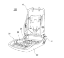
- FIG. 1 is a perspective view showing an external shape of a vehicle seat in which an occupant protection device according to a first embodiment is provided;
- FIG. 1B is a perspective view showing an internal frame structure of the vehicle seat of FIG. 1A.
- 1 is a diagram showing an occupant protection device according to a first embodiment in a side cross section of a vehicle seat;
- 1A and 1B are diagrams explaining the arrangement and operation of the occupant protection device of the first embodiment in relation to the occupant, where (a) shows normal times, (b) shows the early stage of a vehicle emergency, and (c) shows the middle or late stage of a vehicle emergency.
- 3A and 3B are diagrams showing a modified example of the drive device according to the first embodiment, in which FIG. 3A is an overall view similar to FIG. 2, and FIG.
- FIG. 11 is a diagram showing an occupant protection device according to a second embodiment in a side cross section of a vehicle seat.
- FIG. 13 is a diagram showing an occupant protection device according to a modified example of the second embodiment.
- FIG. 11A and 11B are diagrams for explaining the arrangement and operation of an occupant protection device in accordance with a second embodiment in relation to an occupant, where (a) shows a normal state, (b) shows a middle period of a vehicle emergency, and (c) shows a later period of a vehicle emergency.
- 10A and 10B are diagrams for explaining the effect of the passenger protection device according to the second embodiment from a different viewpoint, in which FIG. 10A shows a comparative example and FIG.
- FIG. 10B shows the second embodiment.
- FIG. 13 is a diagram showing an occupant protection device according to another modified example of the second embodiment.
- FIG. 13 is a diagram showing an occupant protection device according to still another modified example of the second embodiment.
- FIG. 13 is a diagram showing an occupant protection device according to still another modified example of the second embodiment.
- 13 is a diagram showing an occupant protection device according to a third embodiment in a side cross section of a vehicle seat.
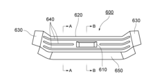
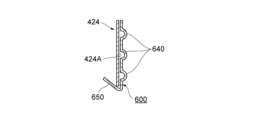
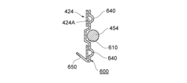
- FIG. FIG. 11 is a perspective view showing a reinforcing beam of an occupant protection device according to a third embodiment. This is a cross-sectional view taken along line AA in FIG. 13. This is a cross-sectional view taken along line B-B of Figure 13.
- FIG. 11 is a perspective view showing a reinforcing beam of an occupant protection device according to a third embodiment. This is a cross-sectional view taken along line AA in FIG. 13. This is a cross-sectional view taken along line B-B of Figure 13.
- FIG. 13 is a perspective view of a reinforcing beam according to another embodiment.
- FIG. 13 is a perspective view showing a reinforcing beam according to yet another embodiment. This is a cross-sectional view taken along the line CC of Figure 15.
- FIG. 11 is a perspective view showing a front portion of a vehicle seat equipped with an occupant protection device according to a third embodiment, with a portion thereof omitted.
- FIG. 16B is a perspective view of the sheet cut in half in the sheet width direction, with a reinforcing beam added to the sheet shown in FIG. 16A.
- FIG. 16C is a partially enlarged view of FIG. 16B.
- FIG. 11 is a partially enlarged view of an occupant protection device according to a third embodiment in a state in which the airbag cushion is folded up.
- 13 is a partially enlarged view of an occupant protection device according to a third embodiment in a state in which an airbag cushion is inflated and deployed.
- FIG. 13 is a graph showing the effect of the occupant protection device according to the third embodiment, illustrating the relationship between the reaction force that the occupant receives from the seat pan in the event of a vehicle emergency and the passage of time.
- 13 is a graph showing the effect of the occupant protection device according to the third embodiment, illustrating the relationship between the chest deflection of an occupant and the passage of time in a vehicle emergency.
- FIG. 11 is a perspective view showing a modified example of the occupant protection device according to the third embodiment, in which the seat pan and the reinforcing beam are integrally formed.
- FIG. 22 is a partial enlarged view of an example obtained by further modifying the modification of FIG. 21 .
- FIG. 11 is a plan view showing the relationship between a folded airbag cushion and a seat pan 424 before inflation and deployment in yet another modified example of the occupant protection device according to the third embodiment. This is a cross-sectional view of A-A in Figure 23.
- FIG. 13 is a diagram showing yet another modified example of the passenger protection device according to the third embodiment.
- the right side of the occupant is referred to as the right direction
- the left side of the occupant is referred to as the left direction
- the axes of the coordinate system are referred to as the left/right direction or the seat width direction.
- the direction of the occupant's head is referred to as upward
- the direction of the occupant's waist is referred to as downward
- the axes of the coordinate system are referred to as the up/down direction.
- occupant refers to a person with a physique equivalent to that of an average male in the United States, conforming to a frontal impact test dummy (Hybrid III AM50 / frontal impact test dummy as determined by the NHTSA [National Highway Traffic Safety Administration] standard [49CFR Part 572 Subparts E and O]), with approximate dimensions of 175 cm height, 88 cm seated height, and 78 kg weight.
- NHTSA National Highway Traffic Safety Administration
- the passenger protection device includes a push-up member that can rotate to push up the seat surface of the seat cushion, and a drive device that applies a force to rotate the push-up member in the event of a vehicle emergency.
- the push-up member has a front portion forward of the rotation center in the front-to-rear direction of the vehicle seat, and the drive device is disposed below the front portion of the push-up member between the front portion of the push-up member and the rotation center, and is configured to apply the force to the front portion of the push-up member.
- the vehicle seat 100 includes a seat back 1 that supports the back of an occupant, a seat cushion 2 on which the occupant sits, and a headrest 3 that supports the head of the occupant.
- the vehicle seat 100 is, for example, a driver's seat or a passenger seat, but may also be a rear seat.
- the seat back 1 and the seat cushion 2 are provided inside with a back frame 10 and a seating frame 20, respectively, which form the framework of the seat.
- the back frame 10 and the seating frame 20 are made of processed metal parts or hard resin, and are connected to each other via a reclining mechanism 4.
- the seating frame 20 has a pair of side frames 22, 22 spaced apart on the left and right, and a seat pan 24 (see Figure 2) is installed between the front parts of the pair of side frames 22, 22.
- the seat pan 24 is located below the front part of the seat cushion 2, and a spring 25 that supports the seat cushion 2 is provided behind the seat pan 24.
- the seat cushion 2 has, for example, a seat pad made of urethane foam material or the like that covers the surface and periphery of the seat frame 20, and a seat cover made of leather, fabric or the like that covers the surface of the seat pad.
- the upper surface of the seat cover forms the surface on which the occupant sits, i.e., the seat surface 26 of the seat cushion 2.
- the occupant protection device 30 is provided inside or below the seat cushion 2.
- the occupant protection device 30 is provided inside the seat cushion 2 and covered by a seat cover.
- the occupant protection device 30 may be provided on the upper surface of the seat pan 24.
- the occupant protection device 30 may be provided on the seating frame 20.
- the occupant protection device 30 is provided below the seat cushion 2, rather than inside the seat cushion 2.
- the occupant protection device 30 is attached to a bracket fixed to the vehicle seat 100 below the seat cushion 2. Below, an example in which the occupant protection device 30 is provided on the upper surface of the seat pan 24 will be described.
- the occupant protection device 30 includes a push-up member 40 that can rotate to push up the seat surface 26 of the seat cushion 2, and a drive device 50 that applies a force to rotate the push-up member 40 in the event of a vehicle emergency.
- a vehicle emergency is a frontal collision of the vehicle.
- the push-up member 40 has a front portion 42 forward of the rotation center 41.
- the front portion 42 is the portion that includes the front end 42a of the push-up member 40, and refers to the portion of the push-up member 40 that is on the front side.
- the push-up member 40 is cut in half at the midpoint in the front-to-rear direction, it can be said that the front half includes at least the front portion 42, and the rear half includes at least the rear portion 43.
- the force from the drive device 50 to the push-up member 40 is not applied to the rear portion 43, but only to the front portion 42.
- the rear end of the push-up member 40 is rotatably supported on the seat pan 24, and this rear end (supported portion) serves as the rotation center 41.
- the rear end of the push-up member 40 may be rotatably supported on the seat frame 20 or a pair of side frames 22, 22.
- the push-up member 40 is made of a hard material (e.g., metal or hard resin).
- the push-up member 40 is formed in a plate shape from a material that is harder than the seat cushion 2 and the airbag cushion 52 described below.
- the push-up member 40 is disposed between the seat cushion 2 and the seat pan 24, and extends in the left-right direction.
- the push-up member 40 is located between a pair of side frames 22, 22, and the length in the left-right direction (i.e., width) of the push-up member 40 is, for example, slightly shorter than the length between the pair of side frames 22, 22.
- the push-up member 40 is bent once in the front-rear direction between the pivot center 41 and the front portion 42. This bent point 44 is located above an imaginary line connecting the pivot center 41 and the front end 42a of the front portion 42. In other words, when the push-up member 40 extends forward from the pivot center 41 toward the front portion 42, it extends upward from the pivot center 41, and then changes angle at the bent point 44 to extend toward the front end 42a.
- the front portion 42 of the push-up member 40 extends parallel to the support surface 24a of the seat pan 24.
- the support surface 24a is a flat surface that is approximately horizontal.
- a portion 45 from the front end 42a of the front portion 42 to the bent point 44 is parallel to the support surface 24a and extends approximately horizontally.
- a portion 46 from the bent point 44 to the rotation center 41 is not parallel to the support surface 24a, but is at an acute angle to the support surface 24a and is inclined upward toward the front.
- the former straight portion 45 is longer in the front-to-rear direction than the latter inclined portion 46.
- the front end 42a of the push-up member 40 faces the front wall 24b of the seat pan 24.
- the front wall 24b extends upward from the front end of the support surface 24a of the seat pan 24, and the push-up member 40 is provided at a position lower than the upper end 24c of the front wall 24b.
- the front wall 24b here has an inverted U-shaped cross section, with the folded-back part of this U forming the upper end 24c.
- the drive unit 50 is disposed below the front portion 42 of the push-up member 40, between the front portion 42 and the pivot center 41.
- the drive unit 50 is configured to apply a force (hereinafter referred to as the "rotational force") that rotates the push-up member 40 to the front portion 42.
- rotational force a force that rotates the push-up member 40 to the front portion 42.
- the drive unit 50 includes an inflatable airbag cushion 52 and an inflator 54 that supplies gas for inflation to the internal space of the airbag cushion 52 in the event of a vehicle emergency.
- the inflator 54 is electrically connected to the vehicle ECU. For example, when the vehicle has a frontal collision, the inflator 54 receives a signal from the vehicle ECU detecting the impact and is activated to instantly supply gas to the airbag cushion 52.
- Various inflators can be used as the inflator 54, such as those filled with a gas generating agent, compressed gas, or both.
- the inflator 54 has an ignition device at the open end of a bottomed cylinder. The ignition device ignites the gas generating agent inside the cylinder to generate gas, and the gas for inflation is supplied into the airbag cushion 52 from multiple nozzles on the circumferential surface of the cylinder.
- the airbag cushion 52 is a bag that inflates and deploys when gas is supplied from the inflator 54.
- the airbag cushion 52 is formed by joining (e.g., sewing or gluing) multiple sheets of base fabric, such as nonwoven fabric, at appropriate positions.
- the airbag cushion 52 is placed on the support surface 24a of the seat pan 24, for example, in a folded state.
- the folding manner is arbitrary, and can be, for example, an accordion shape, a roll shape, or a combination of these.
- the airbag cushion 52 can be attached to the seat pan 24 by various methods.
- the front and rear parts and/or the middle part of the front and rear parts of the airbag cushion 52 can be attached to the seat pan 24 by fasteners such as bolts and rivets.
- the attachment point of the airbag cushion 52 to the seat pan 24 may also serve as the attachment point for attaching the inflator 54 to the seat pan 24.
- the axial direction of the cylinder is aligned with the left and right direction and housed inside the airbag cushion 52.
- the stud bolt 54a protruding from the outer periphery of the cylinder is made to protrude outside the airbag cushion 52, and the seat pan 24 is inserted from the mounting surface 24a side and fastened to the seat pan 24 by the nut 54b.
- the inflator 54 and the airbag cushion 52 are fastened together to the mounting surface 24a of the seat pan 24 by the stud bolt 54a and the nut 54b.
- the airbag cushion 52 and the inflator 54 are located below the front portion 42 of the push-up member 40.
- the airbag cushion 52 begins to inflate and deploy below the front portion 42 of the push-up member 40, contacting the underside of the front portion 42 and applying a rotational force to the front portion 42.
- the push-up member 40 to which the rotational force is applied rotates clockwise around the rotation center 41, pushing up the lower portion of the seat cushion 2 and pushing up the seat surface 26.
- Figure 3 is a diagram explaining the arrangement and operation of the occupant protection device 30 in relation to the occupant P.
- (a) shows normal times
- (b) shows the early stage of a vehicle emergency
- (c) shows the middle or late stage of a vehicle emergency.
- an occupant P is seated on the seat cushion 2 in a normal position and wearing a seat belt (not shown).
- the occupant protection device 30 is disposed in a position where the push-up member 40 pushes up the area near the thighs of the occupant P, close to the buttocks.
- the rotation center 41 of the push-up member 40 is located below the part of the thighs of the occupant P, close to the buttocks.
- the inflator 54 first instantaneously supplies gas to the airbag cushion 52.
- the airbag cushion 52 then begins to inflate and deploy below the front portion 42 of the push-up member 40. At this time, the airbag cushion 52 inflates and deploys upward with the support surface 24a of the seat pan 24 as the reaction surface.
- the airbag cushion 52 is also urged to inflate and deploy upward with the front wall 24b of the seat pan 24 as the reaction surface. That is, as the airbag cushion 52 inflates and deploys forward, it comes into contact with the front wall 24b, receives a reaction force from the front wall 24b, and continues to inflate and deploy upward in the extension direction of the front wall 24b.
- the airbag cushion 52 which expands upward, immediately hits the front part 42 of the push-up member 40, applying a rotational force to the front part 42.
- the push-up member 40 rotates along an arc trajectory centered on the rotation center 41, pushing up the lower part of the seat cushion 2 and pushing up the seat surface 26.
- the seat surface 26 of the seat cushion 2 is pushed up by the entire part of the push-up member 40 that was initially horizontal (part 45 from the front end 42a of the front part 42 to the bent point 44).
- the push-up member 40 begins to lift the area near the thighs of the occupant P, close to the buttocks, via the seat surface 26. Note that in the event of a frontal collision of the vehicle, the occupant P will tend to move forward due to inertia, but the seat belt restrains the lumbar region, restricting the forward movement of the lumbar region.
- the push-up member 40 rotates further, further pushing up the seat surface 26.
- the push-up member 40 rotates to an angle of, for example, a maximum of 5° or more, preferably 10 to 20°, relative to the support surface 24a of the seat pan 24.
- the angle is preferably 5 to 15°. Note that when the airbag cushion 52 inflates and deploys, it does not come into contact with the rear portion 43 of the push-up member 40. In other words, a space is maintained between the rear portion 43 of the push-up member 40 and the seat pan 24.
- the push-up member 40 further lifts the area near the thighs of occupant P close to his buttocks via the seat surface 26, lifting the entire area from the thighs to the knees of occupant P. This acts to rotate the pelvis of occupant P in a clockwise direction. This action prevents the vertebrae of occupant P from being pushed up, and keeps the spine of occupant P downward. In other words, because the spine is not pushed up, no phase difference occurs in the ribs, and no strain is placed on the chest of occupant P, while suppressing forward movement of the waist of occupant P and also suppressing the occurrence of the submarine phenomenon.
- the occupant protection device 30 of embodiment 1 comprises a push-up member 40 that can rotate to push up the seat surface 26 of the seat cushion 2, and a drive unit 50 that applies a force to rotate the push-up member 40 in the event of a vehicle emergency.
- the push-up member 40 has a front portion 42 that is forward of the rotation center 41 in the fore-and-aft direction of the vehicle seat 100, and the drive unit 50 is disposed below the front portion 42 of the push-up member 40 between the front portion 42 of the push-up member 40 and the rotation center 41, and is configured to apply the force to the front portion 42 of the push-up member 40.
- the drive unit 50 is disposed near (below) the portion of the push-up member 40 that receives the force (front portion 42), so the force from the drive unit 50 can be applied immediately (i.e. directly or without releasing the force) to the front portion 42 of the push-up member 40. This makes it easier to ensure the force/amount of pushing up against the seat surface 26. Also, since the push-up is not caused by the airbag itself but by the rotating push-up member 40, the push-up follows the trajectory of the rotation. This makes it easier to stabilize the behavior or direction of the push-up.
- the direction of this rotation is the direction in which a force acts to rotate the pelvis of the occupant P in a clockwise direction, which contributes to improving the lumbar restraint performance of the occupant P, such as suppressing the occurrence of the submarine phenomenon described above.
- the drive unit 50 has an inflatable airbag cushion 52 and an inflator 54 that supplies gas for inflation to the internal space of the airbag cushion 52 in the event of a vehicle emergency, and the airbag cushion 52 is configured to begin inflating and deploying below the front portion 42 of the push-up member 40 and apply the force to the front portion 42 of the push-up member 40.
- the push-up member 40 functions as a pressure-receiving plate that receives the inflation and deployment force of the airbag cushion 52, and the inflation and deployment force of the airbag cushion 52 can be applied to the front part 42 of the push-up member 40 without letting it escape.
- the airbag cushion 52 is configured to be out of contact with the rear portion 43 of the push-up member 40 when inflated and deployed.
- the inflation and deployment force of the airbag cushion 52 can be concentrated on the front part 42 of the push-up member 40.
- the airbag cushion 52 is disposed on the support surface 24a of the seat pan 24 and is configured to inflate and deploy upward with the support surface 24a as a reaction surface.
- This configuration can encourage the rotation of the push-up member 40.
- the support surface 24a is a flat surface, it can increase the ease with which the airbag cushion 52 can be inflated and deployed upward and the ease with which the airbag cushion 52 can be positioned.
- the push-up member 40 has a bent portion 44 above an imaginary line connecting the front end 42a of the front portion 42 and the rotation center 41.
- the front portion 42 of the push-up member 40 can start pushing up the seat surface 26 at an earlier timing than when it is not bent. Also, the space below the front portion 42 of the push-up member 40 can be made smaller than when it is not bent. This makes it possible to minimize the distance between the front portion 42 of the push-up member 40 and the input portion of the rotational force by the drive unit 50 (here, the airbag cushion 52), allowing the rotational force to be input to the front portion 42 efficiently, and also allows the front portion 42 to be separated as far as possible from the seat surface 26, suppressing the impact of the push-up member 40 on seating comfort under normal circumstances.
- the drive unit 50 here, the airbag cushion 52
- embodiment 1 is intended to facilitate understanding of the present invention, and is not intended to limit the interpretation of the present invention.
- the elements of embodiment 1, as well as their arrangement, materials, conditions, shape, size, etc., are not limited to those exemplified, and may be modified as appropriate.
- the driving device 50 may be something other than the combination of the airbag cushion 52 and the inflator 54.
- the driving device 50 may include various actuators such as a motor, a piston, a gear mechanism, a cam mechanism, a slide mechanism, and other structures. An example is described below.
- the drive unit 50 has a power source 72 and a power transmission unit 74 that connects the power source 72 and the push-up member 40 and transmits power from the power source 72 to the push-up member 40 to apply a rotational force to the front part 42 of the push-up member 40.
- the power transmission unit 74 has, for example, a piston connected to the underside of the front part 42 of the push-up member 40 and a cylinder that slidably houses the piston.
- the power source 72 is, for example, composed of a gas generator that can supply high-pressure gas into the cylinder, is electrically connected to the vehicle-side ECU, and operates based on a signal received from the vehicle-side ECU, similar to the inflator 54. When the power source 72 operates, high-pressure gas is supplied into the cylinder, and the high-pressure gas moves the piston, thereby applying a rotational force to the front part 42 of the push-up member 40.
- an airbag cushion is mounted on a flat or low-angle seat pan, so that the airbag cushion is likely to roll toward the front of the vehicle or be crushed when the occupant is restrained.
- the airbag cushion is likely to roll toward the front of the vehicle or be crushed when the occupant is restrained.
- the occupant moves forward in the event of a frontal collision of the vehicle, if the occupant reaches the top of the inflated portion (e.g., spherical shape) of the airbag cushion, it is difficult for the occupant to obtain a reaction force from the airbag cushion when moving further forward.
- the restraint performance is reduced, and the occupant's hips are allowed to rotate forward and the upper torso is allowed to move forward.
- the impact of such problems can be greater in a configuration in which the airbag cushion is disposed relatively forward of the seat cushion, as in the past.
- the occupant protection device according to embodiment 2 adopts a different approach from that of embodiment 1. That is, the occupant protection device according to embodiment 2 is an occupant protection device provided inside or below the seat cushion of a vehicle seat, and includes an inflatable airbag cushion, an inflator that supplies gas for inflation to the internal space of the airbag cushion in the event of a vehicle emergency, and an inclined portion that is disposed on the rear side when the seat cushion is divided into front and rear at the center position in the front-to-rear direction and inclines upward toward the front.
- the airbag cushion is disposed either above or below the inclined portion, or both above and below.
- the airbag cushion is configured so that when the airbag cushion inflates and deploys, the airbag cushion or the inclined portion pushes up the seat surface of the seat cushion diagonally rearward.
- the occupant protection device 230 includes an inflatable airbag cushion 252, an inflator 254 that supplies gas for inflation to the internal space of the airbag cushion 252 in the event of a vehicle emergency, and an inclined portion 255 that is disposed on the rear side when the seat cushion 2 is divided into front and rear portions at the center position in the front-to-rear direction and inclines upward toward the front.
- the airbag cushion 252, the inflator 254, and the inclined portion 255 are provided inside the seat cushion 2.
- the airbag cushion 252 and the inflator 254 are similar to the airbag cushion 52 and the inflator 54 of the first embodiment. However, the airbag cushion 252 is disposed above the inclined portion 255. Here, the airbag cushion 252 is disposed on the upper surface of the inclined portion 255. The airbag cushion 252 inflates and deploys with the inclined portion 255 as a reaction surface, pushing up the seat surface 26 of the seat cushion 2. The direction in which the airbag cushion 252 is urged to inflate and deploy is perpendicular to the inclination direction of the inclined portion 255, which is a direction in which the seat surface 26 is pushed up diagonally backward.
- the inclined portion 255 can be made of metal, resin, etc., but is made of a harder material than the airbag cushion 252 and has high rigidity.
- the inclined portion 255 has strength characteristics similar to those of an iron plate.
- the inclined portion 255 has enough rigidity not to deform even if it receives a force from the airbag cushion 252 as it inflates or has already inflated.
- the ramp portion 255 can be configured as part of the seat pan 24. In other embodiments, the ramp portion 255 can be separate from the seat pan 24 (see FIG. 6). If separate, the ramp portion 255 can be a plate that is fixedly or movably attached to the seat pan 24. In yet another embodiment, the ramp portion 255 does not need to be attached to the structure of the vehicle seat 100 (e.g., the seating frame 20, the seat pan 24).
- the inclined portion 255 is configured as part of the seat pan 24, it can also be considered as an angled seat pan 24.
- This angle is larger than that of conventional seat pans.
- the angle of inclination with respect to the horizontal plane is, for example, 5 to 15 degrees, preferably 10 to 15 degrees, larger than that of conventional seat pans that are flat or have a low angle.
- the plate thickness of the seat pan 24 is set to 0.7 mm or more and 1.4 mm or less.
- the inclined portion 255 and the airbag cushion 252 are positioned on the rear side of the seat cushion 2 in the front-rear direction.
- the highest point of the inclined portion 255 and the airbag cushion 252 is forward of the occupant P's ischial bones and closer to the occupant P's waist.
- This position can be, for example, about 50 to 100 mm rearward from the conventional position.
- the inclined portion 255 and the airbag cushion 252 are positioned relatively high in the vertical direction within the seat cushion 2. This position should be closer to the waist, taking into consideration the reaction force and seating comfort. This improves the initial restraint performance in the event of a vehicle emergency, keeps the occupant P's waist at the same height, and limits the amount of movement of the upper torso, which is effective in reducing the amount of chest deflection.
- FIG. 7 is a diagram explaining the arrangement and operation of the occupant protection device 230 in relation to the occupant P.
- (a) shows normal times
- (b) shows the middle stage of a vehicle emergency
- (c) shows the later stage of a vehicle emergency.
- the left side shows a comparative example
- the right side shows embodiment 2.
- the comparative example uses a conventional seat pan 24', which has a lower angle than the seat pan 24 (inclined portion 255) of embodiment 2.
- FIG. 7(a) an occupant P is seated on the seat cushion 2 in the correct position and wearing a seat belt (not shown).
- the inflator 254 first instantly supplies gas to the airbag cushion 252.
- the airbag cushion 252 then begins to inflate and deploy, inflating diagonally backward with the inclined portion 255 acting as a reaction surface.
- the inflating airbag cushion 252 pushes the seat surface 26 diagonally backward. In relation to the occupant P, the airbag cushion 252 lifts the area near the thighs of the occupant P, close to the buttocks, via the seat surface 26. This causes a force to act on the occupant P's pelvis to rotate in a clockwise direction (backward rotation of the waist). As shown in Figure 7(c), this lifting force and rotation force are greater than those in the comparative example. This reduces the forward movement of the waist and chest of the occupant P in the later stage of a vehicle emergency.
- the inclined portion 255 is disposed relatively rearward on the seat cushion 2, so that the airbag cushion 252, which is inflated and deployed with the inclined portion 255 as a reaction surface, can push up the vicinity of the thighs close to the buttocks of the occupant P (assuming the occupant P is seated on the seat cushion in a normal posture and fastening a seat belt) diagonally rearward.
- This can impart a rotational force in the clockwise direction to the pelvis of the occupant P. This can therefore reduce the forward movement of the waist of the occupant P and also suppress the occurrence of the submarine phenomenon, thereby improving the occupant waist restraint performance.
- the occupant protection device 230 has an inflatable airbag cushion 252 attached to a seat pan 24 that is more angled than conventional ones, and by bending the occupant's waist backward when the airbag inflates and deploys, it is possible to reduce the deflection of the occupant's chest.
- FIG. 8 is a diagram for explaining the effect of embodiment 2 from a different perspective, where (a) shows a comparative example and (b) shows embodiment 2.
- the comparative example does not have an occupant protection device 230.
- embodiment 2 has the following effects.
- the occupant P's sternum falls forward and diagonally downward, and the reduction in the distance between the sternum and the seat belt 300 and the airbag cushion 310 in the direction of movement of the tip of the sternum can be suppressed (i.e., the gap can be increased), and as a result, chest deflection due to the force applied to the occupant P from the seat belt 300 and the airbag cushion 310 can be suppressed.
- multiple airbag cushions may be provided in the front-rear direction.
- the airbag cushions may consist of a front airbag cushion 252a and a rear airbag cushion 252b.
- inflators 254a, 254b are also provided separately, and the front airbag cushion 252a and the rear airbag cushion 252b are configured to be able to inflate and deploy independently of each other.
- the airbag cushion 252 may be disposed below the inclined portion 255.
- the inclined portion 255 is moved by the inflated airbag cushion 252 so that the inclination angle with respect to the horizontal plane increases, thereby pushing up the seat surface 26 of the seat cushion 2.
- the inclined portion 255 may function in the same manner as the push-up member 40 of the first embodiment.
- the inclined portion 255 is made of a plate separate from the seat pan 24, and is rotatably supported on the seat pan 24.
- the inclined portion 255 may be formed of a material having a higher rigidity than the seat pan 24.
- the airbag cushion may be disposed both above and below the inclined portion 255.
- the airbag cushion includes an upper airbag cushion 252-1 disposed above the inclined portion 255, and a lower airbag cushion 252-2 disposed below the inclined portion 255.
- the upper airbag cushion 252-1 is configured to inflate and deploy using the inclined portion 255 as a reaction surface to push up the seat surface 26.
- the lower airbag cushion 252-2 is configured to move the inclined portion 255 by inflating and deploying so that the inclination angle with respect to the horizontal plane increases.
- the aspect shown in FIG. 11 corresponds to a combination of the aspect shown in FIG. 6 and the aspect shown in FIG. 10.
- the upper airbag cushion 252-1 and the lower airbag cushion 252-2 are configured to be inflatable and deployable independently of each other. Therefore, the upper airbag cushion 252-1 and the lower airbag cushion 252-2 are supplied with inflation gas by inflators 254-1, 254-2 that are provided separately for them. By providing the upper airbag cushion 252-1 in addition to the lower airbag cushion 252-2, the occupant's hips can be further encouraged to rotate backward in the event of a vehicle emergency.
- the occupant protection device of embodiment 3 adopts a different approach from the occupant protection devices of embodiments 1 and 2. That is, the occupant protection device of embodiment 3 is an occupant protection device provided inside or below a seat cushion of a vehicle seat, and at least a spring is arranged inside the seat cushion.
- the occupant protection device includes a bridge member extending in the seat width direction at least in front of the spring so as to bridge a pair of side frames arranged inside the seat cushion or vehicle body structural parts on both sides in the seat width direction outside the seat cushion, a recess provided in a rear portion of the bridge member, an airbag cushion that is provided in a folded state and can be inflated and deployed, and an inflator that supplies gas for inflation and deployment to the internal space of the airbag cushion in the event of a vehicle emergency.
- the inflator is provided in the recess, and the airbag cushion, in a folded state, has a storage portion provided in the recess and a main expansion portion disposed outside the recess and toward the rear of the seat cushion, and the main expansion portion is configured to expand and deploy from the upper portion of the bridge member toward the rear of the seat to push up the seat surface of the seat cushion.
- bridge member refers to any member that extends in the seat width direction at least in the forward portion of the spring, and the bridge member itself may overlap the spring, or may be located forward of the front end of the spring without overlapping.
- the bridge member may extend in the seat width direction so as to bridge a pair of side frames or body structural parts, and is typically a seat pan, but may also be other well-known members such as a submarine bar or submarine beam.
- the "side frame” is part of the seating frame that is placed inside the seat cushion.
- the side frame In the case of a vehicle seat where the side frame is not placed inside the seat cushion, it is the “vehicle body structural part” that the bridge member bridges.
- a seat structure where the side frame is not placed inside the seat cushion is typically a vehicle seat for a small truck that is classified as a light truck.
- This vehicle seat is attached directly to the vehicle body by being bolted into mounting holes formed in the vehicle body.
- the vehicle body structural parts on both the left and right sides of the vehicle seat can be, for example, part of the chassis on the outer side in the vehicle width direction, and part of a bar extending in the front-to-rear direction on the inner side in the vehicle width direction.
- the "rear portion of the bridge member" where the “recess” is provided may be the rear of the bridge member, or the rear end of the bridge member. It may also be further rearward of the rear end of the bridge member, in which case it is in the vicinity of the rear end in the fore-and-aft direction (a location not far from the rear end).
- the "recess” may be provided in a part of the bridge member, or in a member other than the bridge member (e.g., a reinforcing beam).
- the "recess” is a part that is recessed in the upper surface of a pair of side frames or vehicle body structural parts that the bridge member spans, and is typically open upward.
- the "recess” is defined by a bottom wall and a vertical wall rising from its periphery, and is open upward.
- the recess may not have a portion of the vertical wall rising from the bottom wall, and may be open in a direction other than the upward direction.
- the recess may be defined by a bottom wall and a vertical wall rising from the front edge of the bottom wall.
- the recess may be formed of a member with a roughly L-shaped cross section.
- a seat pan as a "bridge member.” It also describes an example in which a "recess" is provided in a reinforcing beam, and further describes an example in which the bridge member and reinforcing beam are provided to bridge a pair of side frames.
- the occupant protection device 430 includes a seat pan 424 (bridge member), a reinforcing beam 600, an airbag cushion 452, and an inflator 454.
- the seat pan 424 is located below the front of the seat cushion 2 and extends in the seat width direction so as to bridge the pair of side frames 22, 22 arranged inside the seat cushion 2 (see Figs. 1B and 16A).
- the seat pan 424 is installed between the front parts of the pair of side frames 22, 22 and is bolted to the upper surfaces of the pair of side frames 22, 22 at multiple points (two points) on both the left and right sides (see Fig. 16A).
- the seat pan 424 is made, for example, by processing an iron or steel plate.
- the seat pan 424 is located at least in front of the springs 25 (see Figs. 1B and 16A).
- the springs 25 provide cushioning to the seat cushion 2 and are bent, for example, in a wave shape.
- a plurality of springs 25 are provided in the seat width direction, and each extends in the front-rear direction.
- the other end (front end) of the spring 25 is engaged with a submarine bar 720.
- the submarine bar 720 is intended to suppress the submarine phenomenon, and extends in the seat width direction so as to bridge the pair of side frames 22, 22.
- the submarine bar 720 is located rearward of the seat pan 424. Therefore, the seat pan 424 is located forward of the spring 25.
- the front end of the spring 25 may be connected to the rear of the seat pan 424 or to the reinforcing beam 600.
- the front end of the spring 25 may also overlap the rear of the seat pan 424. In either case, the seat pan 424 only needs to be located at least in a forward portion relative to the spring 25.
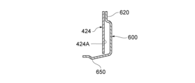
- the reinforcement beam 600 is provided at the rear portion of the seat pan 424.
- the reinforcement beam 600 extends in the seat width direction and is supported by a pair of side frames 22, 22 (see Figure 16B).
- the reinforcing beam 600 has a main body portion 620 in which a recess 610 is formed, and a pair of support receiving portions 630, 630 provided at both ends of the main body portion 620.
- the reinforcing beam 600 is formed by processing, for example, an iron or steel plate.
- the material of the reinforcing beam 600 is the same as the material of the seat pan 424, but may be different.
- the recess 610 is formed in the center of the main body 620 in the longitudinal direction (seat width direction).
- the recess 610 is provided with an inflator 454.
- the inflator 454 is stored in the recess 610.
- the inflator 454 is stored inside the storage portion 452A of the folded airbag cushion 452 (see FIG. 17), and the storage portion 452A that contains the inflator 454 is stored in the recess 610.
- the main body 620 is provided with a number of beads 640.
- the beads 640 are formed as horizontal beads extending in the sheet width direction.
- the beads 640 are formed one each in front of and behind the recess 610, and one each on the left and right sides of the recess 610.
- the beads 640 protrude on the side opposite the recess 610.
- the recess 610 is formed so that the upper surface of the main body 620 is recessed downward, whereas the beads 640 are formed so that the upper surface of the main body 620 is raised upward (see FIG. 13B).
- the main body 620 may be provided with beads 642 that extend in a direction different from that of the beads 640.
- the beads 642 are formed as vertical beads that extend in the front-to-rear direction, with one formed on each side of the recess 610.
- the main body 620 is positioned so that it is inclined upward toward the front. Therefore, the upper surface of the main body 620 is inclined diagonally backward.
- the inclined upper surface of the main body 620 acts as a reaction surface, causing the airbag cushion 452 to inflate and deploy diagonally backward.
- the reinforcing beam 600 further has a flange 650 extending downward from the rear end of the main body 620.
- the flange 650 is inclined forward toward the lower end.
- a bead may be provided on the flange 650.
- a plurality of beads 644 may be provided so as to span both the main body 620 and the flange 650.
- the bead 644 is formed as a vertical bead extending in the front-to-rear direction.
- the support receiving portions 630, 630 are formed to protrude in the seat width direction from both ends of the main body portion 620. As shown in Figures 16B and 16C, the support receiving portions 630, 630 are supported by the side frames 22, 22, respectively.
- the support receiving portions 630, 630 may be supported by the side frames 22, 22 via the seat pan 424, or may be supported by the side frames 22, 22 without via the seat pan 424.
- the support receiving portions 630, 630 may also be supported by resting on the side frames 22, 22 via the seat pan 424 or directly, and may be fixed by welding or bolting, etc.
- the reinforcement beam 600 has a portion that overlaps the upper part of the seat pan 424 at the rear of the seat pan 424 (see Figures 12, 13A, 13B, 15A, 16A, 16B).
- the main body portion 620 and support receiving portions 630, 630 of the reinforcement beam 600 overlap the upper rear portion 424A of the seat pan 424.
- the plate thickness of the reinforcement beam 600 is thinner than the plate thickness of the seat pan 424.
- the inflator 454 is similar to the inflator 54 of the first embodiment.
- the inflator 454 has an ignition device at the open end of a bottomed cylinder, and in the event of a vehicle emergency, generates gas by igniting a gas generating agent inside the cylinder, and supplies the gas for inflation and deployment to the internal space of the airbag cushion 452 from multiple ejection holes on the circumferential surface of the cylinder.
- the airbag cushion 452 is similar to the airbag cushion 52 of the first embodiment, but is arranged differently.
- the airbag cushion 452 is a bag body, and when gas is supplied from the inflator 454, it inflates and deploys so as to push up the seat surface 26 of the seat cushion 2.
- the airbag cushion 452 is formed by joining (for example, sewing or gluing) multiple pieces of base fabric, such as nonwoven fabric, at appropriate positions.
- the airbag cushion 452 is folded as shown in FIG. 17.
- the manner of folding is arbitrary, and it can be, for example, an accordion shape, a roll shape, or a combination of these.
- the airbag cushion 452 has a storage portion 452A provided in the recess 610, and a main inflatable portion 452B arranged outside the recess 610 and extending to the rear of the seat cushion 2.
- the storage section 452A houses the inflator 454 inside.
- the storage section 452A and the inflator 454 are fastened together to the seat pan 424 or the reinforcing beam 600.
- the inflator 454 it is housed inside the storage section 452A with the axis of the cylinder aligned with the seat width direction and housed in the recess 610.
- the stud bolt 454a protruding from the outer periphery of the cylinder is made to protrude outside the storage section 452A, and is inserted through the recess 610 and the seat pan 424, and fastened to the seat pan 424 by a nut (not shown).
- the inflator 454 and the storage section 452A of the airbag cushion 452 are fastened together to the seat pan 424 by the stud bolt 454a and the nut.
- the main expansion portion 452B may correspond to the portion of the folded airbag cushion 452 excluding the storage portion 452A.
- the inside of the main expansion portion 452B is connected to the inside of the storage portion 452A and receives a supply of gas from the inflator 454. This causes the main expansion portion 452B to expand and deploy.
- the main expansion portion 452B expands and deploys from the top of the seat pan 424 toward the rear of the seat as a whole, and the expanding main expansion portion 452B pushes up the seat surface of the seat cushion 2.
- the main expansion portion 452B expands and deploys so as to push up the seat surface of the seat cushion 2 diagonally backward, using the upper surface of the main body portion 620, which is inclined diagonally downward and backward, as a reaction surface.
- the center position 452C of the inflated airbag cushion 452 is located rearward of the installation position 454C of the inflator 454.
- the center position 452C of the airbag cushion 452 is the vertical center position (position between the upper end and the lower end) of the inflated airbag cushion 452, and is also the front-rear center position (position between the front end and the rear end) of the inflated airbag cushion 452.
- the installation position 454C of the inflator 454 is located, for example, on the axis of the bottomed cylinder of the inflator 454 fixed to the recess 610.
- the center position 452C of the airbag cushion 452 is located approximately directly above the center position 720C of the submarine bar 720.
- the center position 452C of the airbag cushion 452, even in the folded state before inflation and deployment, is located rearward of the installation position 454C of the inflator 454, and is located approximately directly above the center position 720C of the submarine bar 720 (see Figure 17).
- the occupant protection device 430 includes a seat pan 424 (bridge member) that extends in the seat width direction so as to bridge a pair of side frames 22, 22 at least in the front portion of the spring 25, a recess 610 provided in the rear portion of the seat pan 424, an airbag cushion 452 that is folded and can be inflated and deployed, and an inflator 454 that supplies gas for inflating and deploying to the internal space of the airbag cushion 452 in the event of a vehicle emergency.
- a seat pan 424 bridge member
- the airbag cushion 452 that is folded and can be inflated and deployed
- an inflator 454 that supplies gas for inflating and deploying to the internal space of the airbag cushion 452 in the event of a vehicle emergency.
- the inflator 454 is provided in the recess 610, and the airbag cushion 452 has a storage portion 452A provided in the recess 610 in a folded state, and a main expansion portion 452B that is arranged outside the recess 610 and extending to the rear of the seat cushion 2, and the main expansion portion 452B is configured to inflate and deploy from the upper portion of the seat pan 424 toward the rear of the seat to push up the seat surface 26 of the seat cushion 2.
- the occupant protection device 430 further includes a reinforcing beam 600 at the rear portion of the seat pan 424, which extends in the seat width direction and is supported by a pair of side frames 22, 22, and the recess 610 is provided in the reinforcing beam 600.
- This configuration can prevent the seat pan 424 from being significantly deformed by the inflated airbag cushion 452.
- the load from the inflated airbag cushion 452 is input to the recess 610 of the reinforcement beam 600, but the input load can be released to the pair of side frames 22, 22 via the reinforcement beam 600. This prevents the seat pan 424 from being deformed.
- the main inflatable portion 452B of the airbag cushion 452 can be inflated from the top of the seat pan 424 toward the rear of the seat and push up the seat surface 26 of the seat cushion 2, ensuring the restraint performance of the pelvis and lower back of the occupant P.
- the inflator 454 is stored in the recess 610, and the seat comfort of the seat cushion 2 is not compromised.
- the reinforcement beam 600 is provided with beads 640, 642, and 644. According to this aspect, the rigidity of the reinforcement beam 600 itself can be increased.
- the reinforcing beam 600 has a main body portion 620 that is inclined upward toward the front and has a recess 610 formed therein, and a pair of support receiving portions 630, 630 that are provided at both ends of the main body portion 620 and are supported by a pair of side frames 22, 22.
- the inclination of the main body portion 620 can be effectively used to push the seat surface 26 diagonally upward and rearward with the main expansion portion 452B. This further reduces the forward movement of the occupant P's waist and also improves the occupant waist restraint performance, such as suppressing the occurrence of the submarine phenomenon.
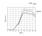
- FIG. 19 shows the relationship between the reaction force (vertical axis) that the occupant receives from the seat pan during a vehicle emergency (when the airbag cushion is inflated and deployed) and the passage of time (horizontal axis). Due to the reaction force, the vector direction is reversed, and therefore the vertical axis is in the negative direction from 0.
- the reference example is an example in which the airbag cushion 452 is omitted from the third embodiment.
- Comparative example 1 is an example in which the reinforcing beam 600 is omitted from the third embodiment, and the inflator 454 is provided on the seat pan 424. As can be seen from FIG.
- the reaction force that the occupant receives from the seat pan 424 is smaller from the initial stage of inflation and deployment (30 ms) than in the first comparative example. This means that the input load to the seat pan 424 is smaller. Therefore, while the seat pan can be deformed in the first comparative example, the deformation of the seat pan 424 can be suppressed in the third embodiment.
- Figure 20 shows the force (force from the seat belt) that an occupant's chest receives in a vehicle emergency (when the airbag cushion is inflated and deployed) as a value of chest deflection, and shows the relationship between chest deflection (vertical axis) and the passage of time (horizontal axis).
- the reference example and comparative example 1 are examples similar to the case of Figure 19. As shown in Figure 20, it can be seen that in embodiment 3, the value of chest deflection is smaller than in comparative example 1.
- the seat pan 424 and the reinforcing beam 600 with the recess 610 are separate bodies, but they may be of an integral structure.
- This integral member may be made capable of receiving an input load of, for example, 5 kN or more through the inflated airbag cushion 452.
- the submarine bar 720 may be omitted.
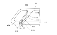
- Figure 21 is a partially enlarged perspective view showing an example in which such an integral member is used. As shown in Figure 21, there is a hole 810 in the bridge portion 800 (part of the seat pan 424), and the harness for the inflator 454 passes through the hole 810 and extends below the seat. This keeps the harness length short.
- the recess 610 and flange 650 formed in the reinforcing beam 600 in the above embodiment are formed in the rear portion of the seat pan 424.
- the recess 610A is recessed into the upper surfaces of the side frames 22, 22, and can be defined by a bottom wall 611A and left and right side walls 611B, 611B.
- the side walls 611B, 611B rise from both ends of the bottom wall 611A in the seat width direction and are supported by a pair of side frames 22, 22.
- An inflator 454 is provided on the bottom wall 611A.
- a flange 650 is formed to rise from the front end of the bottom wall 611A.
- FIG. 22 is a partial enlarged view of an example that is a further modification of the modification of FIG. 21.
- the seat pan 424 has a recess 610B defined by a bottom wall 911A and a vertical wall 911C.
- the recess 610B is a member with a generally L-shaped cross section, and the vertical wall 911C is a portion that corresponds to the flange 650.
- FIG. 23 and 23A show the relationship between the folded airbag cushion 452 and the seat pan 424, etc., before inflation and deployment in a modified example of embodiment 3. Note that in this embodiment, the recess 610 and flange 650 formed in the reinforcing beam 600 are formed in the rear portion of the seat pan 424.
- the inflator 454 and storage portion 452A of the airbag cushion 452 are fixed to the rear portion (here, the rear end) of the seat pan 424 with bolts 454A and nuts 454B.
- the main inflation portion 452B of the airbag cushion 452 is positioned largely above the spring 25 behind the seat.
- L1 represents the distance from the fixing point to the front end of the main inflation portion 452B
- L2 represents the distance from the fixing point to the rear end of the main inflation portion 452B.
- the main inflatable portion 452B of the airbag cushion 452 extends rearward so that the bottom wall 911A or the vertical wall 911C (flange portion) can withstand a load of at least 5 kN (input load on the occupant's waist) when the airbag cushion 452 is fully inflated and deployed.
- FIG. 24 shows another modified example of embodiment 3.
- a recess 610C is provided at the rear end of the seat pan 424.
- the recess 610C is defined by a bottom wall 921A, a vertical wall 921D, and a vertical wall 921E.
- the vertical wall 921E rises from the front end of the bottom wall 921A and connects to the rear end of the seat pan 424.
- the vertical wall 921E is provided so as to form an acute angle with respect to the horizontal direction of the seat or the seat pan 424 ( ⁇ 90 degrees). ⁇ is, for example, 25 to 45 degrees.
- the vertical wall 921D rises from the rear end of the bottom wall 921A, and its tip is a free end.
- the vertical wall 921D faces the vertical wall 921E.
- the vertical wall 921D may be parallel to the vertical wall 921E, or may be slightly angled with respect to the vertical wall 921E.
- Reference numeral 1000 denotes the direction in which the occupant's hips move in, which is approximately parallel to the vertical walls 921D and 921E.
- the recess 610C can be formed in the reinforcing beam 600A. In other embodiments, some or all of the walls forming the recess 610C can be integral with the seat pan 424.
- the vertical wall 921E can be formed integral with the seat pan 424 and extend diagonally downward and forward from the rear end of the seat pan 424.
- An occupant protection device provided inside or below a seat cushion of a vehicle seat, A push-up member that is rotatable so as to push up the seat surface of the seat cushion; a drive device that applies a force to rotate the push-up member in the event of a vehicle emergency, the push-up member has a front portion forward of a rotation center in a front-rear direction of the vehicle seat, An occupant protection device, wherein the drive device is positioned below the front portion of the push-up member between the front portion of the push-up member and the pivot center, and is configured to apply the force to the front portion of the push-up member.
- the drive device is an inflatable airbag cushion; an inflator that supplies gas for inflation and deployment to the internal space of the airbag cushion in the event of a vehicle emergency;
- Embodiment A-4 The occupant protection device according to embodiment A-2 or A-3, wherein the airbag cushion is arranged on a support surface of the seat pan and configured to inflate and deploy upward with the support surface as a reaction surface.
- the seat pan has a front wall extending upward from a front end of the placement surface, An occupant protection device according to any one of embodiments A-4 to A-9, wherein the push-up member is provided at a position lower than the upper end of the front wall.
- the drive device is A power source;
- An occupant protection device provided inside or below a seat cushion of a vehicle seat, an inflatable airbag cushion; an inflator for supplying gas for inflation and deployment to an internal space of the airbag cushion in the event of a vehicle emergency; a sloping portion disposed on the rear side when the seat cushion is divided into front and rear portions at a central position in the front-rear direction and sloping upward toward the front,
- the airbag cushion is disposed above or below the inclined portion, or both above and below the inclined portion,
- An occupant protection device configured such that, when the airbag cushion is inflated and deployed, the airbag cushion and/or the inclined portion pushes up a seat surface of the seat cushion in an obliquely rearward direction.
- Emodiment B-2 The occupant protection device described in embodiment B-1, wherein the airbag cushion is arranged above the inclined portion and is configured to inflate and deploy using the inclined portion as a reaction surface to push up the seat surface of the seat cushion.
- Embodiment B-3 The airbag cushion is disposed below the inclined portion, The occupant protection device described in embodiment B-1, wherein the inclined portion is configured to be moved by the inflated and deployed airbag cushion so that the inclination angle with respect to the horizontal plane is increased, thereby pushing up the seat surface of the seat cushion.
- the airbag cushion includes an upper airbag cushion arranged above the inclined portion and a lower airbag cushion arranged below the inclined portion,
- the upper airbag cushion is configured to inflate and deploy using the inclined portion as a reaction surface to push up the seat surface of the seat cushion,
- Embodiment B-6 An occupant protection device according to any one of embodiments B-1 to B-4, wherein the inclined portion is separate from the seat pan and is configured as a plate attached to the seat pan.
- Embodiment B-7 The occupant protection device according to any one of embodiments B-1 to B-6, wherein a plurality of the airbag cushions are provided in the front-rear direction.
- Emodiment B-8 When an occupant is seated on the seat cushion in a normal position and fastening a seat belt, the occupant protection device according to any one of embodiments B-1 to B-7, wherein the inflation and deployment of the airbag cushion encourages the occupant's waist to rotate backward.
- An occupant protection device provided inside or below a seat cushion of a vehicle seat, the occupant protection device including a seating frame having a pair of side frames and a spring disposed within the seat cushion, a bridge member extending in a seat width direction so as to bridge a pair of side frames disposed in the seat cushion or a vehicle body structure portion on both sides in the seat width direction outside the seat cushion at least in a front portion of the spring; a recess provided in a rear portion of the bridge member; an airbag cushion that is folded and can be inflated and deployed; an inflator that supplies gas for inflation and deployment to the internal space of the airbag cushion in the event of a vehicle emergency; The inflator is provided in the recess, The airbag cushion, in a folded state, A storage portion provided in the recess; a main inflatable portion disposed outside the recess and toward the rear of the seat cushion; The main inflatable portion is configured to inflate and deploy from an upper portion of the bridge member toward the rear of the seat to
- a reinforcing beam is further provided at a rear portion of the bridge member, the reinforcing beam extending in the seat width direction and supported by the pair of side frames or the vehicle body structure portion, An occupant protection device as described in embodiment C-1, wherein the recess is provided in the reinforcing beam.
- the bridge member is a seat pan, An occupant protection device as described in embodiment C-2 or C-3, wherein the plate thickness of the reinforcing beam is thinner than the plate thickness of the seat pan.
- the reinforcing beam is a main body portion inclined upward toward the front and having the recess formed therein;
Landscapes
- Engineering & Computer Science (AREA)
- Mechanical Engineering (AREA)
- Aviation & Aerospace Engineering (AREA)
- Transportation (AREA)
- Physics & Mathematics (AREA)
- Fluid Mechanics (AREA)
- Seats For Vehicles (AREA)
- Air Bags (AREA)
Abstract
Description
上述したように、車両シートのシートクッションの内部又は下方に設けられる従来の乗員保護装置の課題として、例えば、エアバッグがシートクッションの前端下部を直接かつ上方に(鉛直方向に)押し上げることにより、エアバッグによる押上げの力又は量が十分でなく、乗員の膝を効果的に持ち上げることができないことがある。
従来の乗員保護装置には、上記の課題とは別の又は関連する課題もある。具体的には、従来は平面もしくは低角度のシートパンにエアバッグクッションを搭載しているため、乗員拘束時にエアバッグクッションが車両前方側に転がったり、潰れやすい。車両が前方衝突した場合の乗員の前方移動により、乗員がエアバッグクッションの膨張部(例えば球形状)の頂点に達すると、それより前方移動する際に、エアバッグクッションからの反力を得られにくい。その結果、拘束性能が低下し、乗員の腰の前方回転と上胴部の前方移動を許容してしまう。このような問題の影響は、従来のように、エアバッグクッションがシートクッションの比較的前方側に配置される構成ほど、より大きくなり得る。
従来の乗員保護装置には、上記の課題とは別の又は関連する課題もある。具体的には、従来、シートパンの態様によっては、膨張展開したエアバッグクッションによってシートパンが大きく変形し得る。すると、膨張展開していく際にシートパンから反力を受けるエアバッグクッションが、シートパンの大きな変形によって、本来の意図した展開挙動とならなくなり得る。その結果、エアバッグクッションによる座面の押上げが十分でなくなり、乗員の骨盤・腰部の拘束性能が低下するおそれがあり得る。
[実施態様A-1]
車両シートのシートクッションの内部又は下方に設けられる乗員保護装置であって、
前記シートクッションの座面を押し上げるように回動可能な押上げ部材と、
車両緊急時に、前記押上げ部材が回動する力を印加する駆動装置と、を備え、
前記押上げ部材は、回動中心よりも前記車両シートの前後方向における前方側に前部を有し、
前記駆動装置は、前記押上げ部材の前部と前記回動中心との間のうち、前記押上げ部材の前部の下方に配置され、前記押上げ部材の前部に対して前記力を印加するように構成されている、乗員保護装置。
前記駆動装置は、
膨張展開可能なエアバッグクッションと、
車両緊急時に前記エアバッグクッションの内部空間に膨張展開用のガスを供給するインフレータと、を有し、
前記エアバッグクッションは、前記押上げ部材の前部の下方で膨張展開を開始して、前記押上げ部材の前部に対して前記力を印加するように構成されている、実施態様A-1に記載の乗員保護装置。
前記エアバッグクッションは、膨張展開した際、前記押上げ部材の後部に対して非接触となるように構成されている、実施態様A-1又は2に記載の乗員保護装置。
前記エアバッグクッションは、シートパンの載置面上に配置され、当該載置面を反力面として上方に膨張展開するように構成されている、実施態様A-2又は3に記載の乗員保護装置。
前記載置面は、平坦面である、実施態様A-4に記載の乗員保護装置。
前記押上げ部材の前部は、前記載置面と平行に延在する、実施態様A-4又は5に記載の乗員保護装置。
前記押上げ部材は、前記前部と前記回動中心との間で1回屈曲しており、その屈曲箇所から前記前部の前端にかけての部分が前記載置面と平行に延在する、実施態様A-4から6のいずれかに記載の乗員保護装置。
前記押上げ部材は、前記回動中心から前記屈曲箇所にかけて、前記車両シートの前後方向における前方に向かって上方へと傾斜している、実施態様A-7に記載の乗員保護装置。
前記押上げ部材は、前記前部の前端から前記屈曲箇所にかけての部分が、前記屈曲箇所から前記回動中心にかけての部分よりも長い、実施態様A-8に記載の乗員保護装置。
前記シートパンは、前記載置面の前端から上方に延びる前方壁を有しており、
前記押上げ部材は、前記前方壁の上端よりも低い位置に設けられている、実施態様A-4から9のいずれかに記載の乗員保護装置。
前記エアバッグクッションは、シートパンの前方壁を反力面として上方への膨張展開を促されるように構成されている、実施態様A-2から10のいずれかに記載の乗員保護装置。
前記インフレータは、前記載置面側から挿通されたボルトを介して前記シートパンに固定されている、実施態様A-4から11のいずれかに記載の乗員保護装置。
前記駆動装置は、
動力源と、
前記動力源と前記押上げ部材とを連結し、かつ、前記押上げ部材の前部に対して前記力を印加するために前記動力源からの動力を前記押上げ部材に伝達する動力伝達部と、を有する、実施態様A-1に記載の乗員保護装置。
前記押上げ部材は、前記前部の前端と前記回動中心とを結ぶ仮想線よりも上側に、屈曲箇所を有する、実施態様A-1~6又は13のいずれかに記載の乗員保護装置。
車両シートのシートクッションの内部又は下方に設けられる乗員保護装置であって、
膨張展開可能なエアバッグクッションと、
車両緊急時に前記エアバッグクッションの内部空間に膨張展開用のガスを供給するインフレータと、
前記シートクッションを前後方向の中央位置において前後にわけたときに、後方側に配置されて、前方に向かって上方へと傾斜した傾斜部と、を備え、
前記エアバッグクッションは、前記傾斜部の上下いずれか又は上下の両方に配置され、
前記エアバッグクッションの膨張展開によって、前記エアバッグクッション及び/又は前記傾斜部が、前記シートクッションの座面を斜め後ろ方向に押し上げるように構成されている、乗員保護装置。
前記エアバッグクッションは、前記傾斜部の上側に配置され、当該傾斜部を反力面として膨張展開して前記シートクッションの座面を押し上げるように構成されている、実施態様B-1に記載の乗員保護装置。
前記エアバッグクッションは、前記傾斜部の下側に配置され、
前記傾斜部は、膨張展開した前記エアバッグクッションによって水平面に対する傾斜角度が大きくなるように可動させられて、前記シートクッションの座面を押し上げるように構成されている、実施態様B-1に記載の乗員保護装置。
前記エアバッグクッションは、前記傾斜部の上側に配置された上側エアバッグクッションと、前記傾斜部の下側に配置された下側エアバッグクッションと、を備え、
前記上側エアバッグクッションは、当該傾斜部を反力面として膨張展開して前記シートクッションの座面を押し上げるように構成され、
前記下側エアバッグクッションは、膨張展開によって、水平面に対する傾斜角度が大きくなるように前記傾斜部を可動させるように構成されている、実施態様B-1に記載の乗員保護装置。
前記傾斜部は、シートパンの一部である、実施態様B-1~4のいずれかに記載の乗員保護装置。
前記傾斜部は、シートパンとは別体であり、当該シートパンに取り付けられたプレートで構成されている、実施態様B-1~4のいずれかに記載の乗員保護装置。
前記エアバッグクッションは、前後方向に複数設けられている、実施態様B-1~6のいずれかに記載の乗員保護装置。
乗員が正規の姿勢で前記シートクッションに着座してシートベルトをつけている場合に、
前記エアバッグクッションの膨張展開によって、前記乗員の腰の後屈回転が促される、実施態様B-1~7のいずれかに記載の乗員保護装置。
車両シートのシートクッションの内部又は下方に設けられる乗員保護装置であって、当該シートクッション内に、一対のサイドフレームを有する着座フレームとスプリングとが配置された乗員保護装置であって、
前記スプリングに対して少なくともその前方部分で、前記シートクッション内に配置された一対のサイドフレーム又は前記シートクッションの外部でシート幅方向における両側にある車体構造部分を橋渡しするようにシート幅方向に延在するブリッジ部材と、
前記ブリッジ部材の後方部分に設けられた凹部と、
折り畳まれて設けられ、膨張展開可能なエアバッグクッションと、
車両緊急時に前記エアバッグクッションの内部空間に膨張展開用のガスを供給するインフレータと、を備え、
前記インフレータは、前記凹部に設けられ、
前記エアバッグクッションは、折り畳まれた状態で、
前記凹部に設けられる収納部分と、
前記凹部の外側で、前記シートクッションの後方にかけて配置される主膨張部分と、を有し、
前記主膨張部分は、前記ブリッジ部材の上部からシート後方に向かって膨張展開して前記シートクッションの座面を押し上げるように構成されている、乗員保護装置。
前記ブリッジ部材の後方部分に、シート幅方向に延在して前記一対のサイドフレーム又は前記車体構造部分に支持される補強ビームをさらに備え、
前記凹部は、前記補強ビームに設けられている、実施態様C-1に記載の乗員保護装置。
前記補強ビームは、前記ブリッジ部材の上部に重なる部分を有する、実施態様C-2に記載の乗員保護装置。
前記ブリッジ部材は、シートパンであり、
前記補強ビームの板厚は、前記シートパンの板厚よりも薄い、実施態様C-2又はC-3に記載の乗員保護装置。
前記補強ビームには、ビードが設けられている、実施態様C-2~4のいずれかに記載の乗員保護装置。
前記補強ビームは、
前方に向かって上方へと傾斜し、前記凹部が形成された本体部と、
前記本体部の両端に設けられ、前記一対のサイドフレーム又は前記車体構造部分に支持される一対の支持受け部と、を有する、実施態様C-2~5のいずれかに記載の乗員保護装置。
前記補強ビームは、前記本体部の後端から下側に向けて延在するフランジをさらに有する、実施態様C-6に記載の乗員保護装置。
前記インフレータは、前記収納部分の内部に収容され、前記収納部分は、前記凹部に収納されている、実施態様C-1~7のいずれかに記載の乗員保護装置。
前記凹部は、前記スプリングの前端部近傍に位置する、実施態様C-1~8のいずれかに記載の乗員保護装置。
Claims (24)
- 車両シートのシートクッションの内部又は下方に設けられる乗員保護装置であって、
前記シートクッションの座面を押し上げるように回動可能な押上げ部材と、
車両緊急時に、前記押上げ部材が回動する力を印加する駆動装置と、を備え、
前記押上げ部材は、回動中心よりも前記車両シートの前後方向における前方側に前部を有し、
前記駆動装置は、前記押上げ部材の前部と前記回動中心との間のうち、前記押上げ部材の前部の下方に配置され、前記押上げ部材の前部に対して前記力を印加するように構成されている、乗員保護装置。 - 前記駆動装置は、
膨張展開可能なエアバッグクッションと、
車両緊急時に前記エアバッグクッションの内部空間に膨張展開用のガスを供給するインフレータと、を有し、
前記エアバッグクッションは、前記押上げ部材の前部の下方で膨張展開を開始して、前記押上げ部材の前部に対して前記力を印加するように構成されている、請求項1に記載の乗員保護装置。 - 前記エアバッグクッションは、シートパンの載置面上に配置され、当該載置面を反力面として上方に膨張展開するように構成されている、請求項2に記載の乗員保護装置。
- 前記エアバッグクッションは、シートパンの前方壁を反力面として上方への膨張展開を促されるように構成されている、請求項2に記載の乗員保護装置。
- 前記押上げ部材は、前記前部と前記回動中心との間で1回屈曲しており、その屈曲箇所から前記前部の前端にかけての部分が前記載置面と平行に延在する、請求項3に記載の乗員保護装置。
- 前記駆動装置は、
動力源と、
前記動力源と前記押上げ部材とを連結し、かつ、前記押上げ部材の前部に対して前記力を印加するために前記動力源からの動力を前記押上げ部材に伝達する動力伝達部と、を有する、請求項1に記載の乗員保護装置。 - 前記押上げ部材は、前記前部の前端と前記回動中心とを結ぶ仮想線よりも上側に、屈曲箇所を有する、請求項1、2、3、4又は6に記載の乗員保護装置。
- 車両シートのシートクッションの内部又は下方に設けられる乗員保護装置であって、
膨張展開可能なエアバッグクッションと、
車両緊急時に前記エアバッグクッションの内部空間に膨張展開用のガスを供給するインフレータと、
前記シートクッションを前後方向の中央位置において前後にわけたときに、後方側に配置されて、前方に向かって上方へと傾斜した傾斜部と、を備え、
前記エアバッグクッションは、前記傾斜部の上下いずれか又は上下の両方に配置され、
前記エアバッグクッションの膨張展開によって、前記エアバッグクッション及び/又は前記傾斜部が、前記シートクッションの座面を斜め後ろ方向に押し上げるように構成されている、乗員保護装置。 - 前記エアバッグクッションは、前記傾斜部の上側に配置され、当該傾斜部を反力面として膨張展開して前記シートクッションの座面を押し上げるように構成されている、請求項8に記載の乗員保護装置。
- 前記エアバッグクッションは、前記傾斜部の下側に配置され、
前記傾斜部は、膨張展開した前記エアバッグクッションによって水平面に対する傾斜角度が大きくなるように可動させられて、前記シートクッションの座面を押し上げるように構成されている、請求項8に記載の乗員保護装置。 - 前記エアバッグクッションは、前記傾斜部の上側に配置された上側エアバッグクッションと、前記傾斜部の下側に配置された下側エアバッグクッションと、を備え、
前記上側エアバッグクッションは、当該傾斜部を反力面として膨張展開して前記シートクッションの座面を押し上げるように構成され、
前記下側エアバッグクッションは、膨張展開によって、水平面に対する傾斜角度が大きくなるように前記傾斜部を可動させるように構成されている、請求項8に記載の乗員保護装置。 - 前記傾斜部は、シートパンの一部である、請求項8から11のいずれか一項に記載の乗員保護装置。
- 前記傾斜部は、シートパンとは別体であり、当該シートパンに取り付けられたプレートで構成されている、請求項8から11のいずれか一項に記載の乗員保護装置。
- 前記エアバッグクッションは、前後方向に複数設けられている、請求項8から11のいずれか一項に記載の乗員保護装置。
- 乗員が正規の姿勢で前記シートクッションに着座してシートベルトをつけている場合に、
前記エアバッグクッションの膨張展開によって、前記乗員の腰の後屈回転が促される、請求項8から11のいずれか一項に記載の乗員保護装置。 - 車両シートのシートクッションの内部又は下方に設けられる乗員保護装置であって、当該シートクッション内に少なくともスプリングが配置された乗員保護装置であって、
前記スプリングに対して少なくともその前方部分で、前記シートクッション内に配置された一対のサイドフレーム又は前記シートクッションの外部でシート幅方向における両側にある車体構造部分を橋渡しするようにシート幅方向に延在するブリッジ部材と、
前記ブリッジ部材の後方部分に設けられた凹部と、
折り畳まれて設けられ、膨張展開可能なエアバッグクッションと、
車両緊急時に前記エアバッグクッションの内部空間に膨張展開用のガスを供給するインフレータと、を備え、
前記インフレータは、前記凹部に設けられ、
前記エアバッグクッションは、折り畳まれた状態で、
前記凹部に設けられる収納部分と、
前記凹部の外側で、前記シートクッションの後方にかけて配置される主膨張部分と、を有し、
前記主膨張部分は、前記ブリッジ部材の上部からシート後方に向かって膨張展開して前記シートクッションの座面を押し上げるように構成されている、乗員保護装置。 - 前記ブリッジ部材の後方部分に、シート幅方向に延在して前記一対のサイドフレーム又は前記車体構造部分に支持される補強ビームをさらに備え、
前記凹部は、前記補強ビームに設けられている、請求項16に記載の乗員保護装置。 - 前記補強ビームは、前記ブリッジ部材の上部に重なる部分を有する、請求項17に記載の乗員保護装置。
- 前記ブリッジ部材は、シートパンであり、
前記補強ビームの板厚は、前記シートパンの板厚よりも薄い、請求項17又は18に記載の乗員保護装置。 - 前記補強ビームには、ビードが設けられている、請求項17又は18に記載の乗員保護装置。
- 前記補強ビームは、
前方に向かって上方へと傾斜し、前記凹部が形成された本体部と、
前記本体部の両端に設けられ、前記一対のサイドフレーム又は前記車体構造部分に支持される一対の支持受け部と、を有する、請求項17又は18に記載の乗員保護装置。 - 前記補強ビームは、前記本体部の後端から下側に向けて延在するフランジをさらに有する、請求項21に記載の乗員保護装置。
- 前記インフレータは、前記収納部分の内部に収容され、
前記収納部分は、前記凹部に収納されている、請求項16から18のいずれか一項に記載の乗員保護装置。 - 前記凹部は、前記スプリングの前端部近傍に位置する、請求項16から18のいずれか一項に記載の乗員保護装置。
Priority Applications (4)
| Application Number | Priority Date | Filing Date | Title |
|---|---|---|---|
| JP2025530251A JPWO2025005286A1 (ja) | 2023-06-30 | 2024-06-28 | |
| EP24832142.4A EP4737208A1 (en) | 2023-06-30 | 2024-06-28 | Occupant protection device |
| KR1020257043443A KR20260016550A (ko) | 2023-06-30 | 2024-06-28 | 승차인 보호 장치 |
| CN202480043701.5A CN121398996A (zh) | 2023-06-30 | 2024-06-28 | 乘员保护装置 |
Applications Claiming Priority (4)
| Application Number | Priority Date | Filing Date | Title |
|---|---|---|---|
| JP2023108678 | 2023-06-30 | ||
| JP2023-108678 | 2023-06-30 | ||
| PCT/JP2024/019637 WO2025004672A1 (ja) | 2023-06-30 | 2024-05-29 | 乗員保護装置 |
| JPPCT/JP2024/019637 | 2024-05-29 |
Publications (1)
| Publication Number | Publication Date |
|---|---|
| WO2025005286A1 true WO2025005286A1 (ja) | 2025-01-02 |
Family
ID=93938222
Family Applications (2)
| Application Number | Title | Priority Date | Filing Date |
|---|---|---|---|
| PCT/JP2024/019637 Ceased WO2025004672A1 (ja) | 2023-06-30 | 2024-05-29 | 乗員保護装置 |
| PCT/JP2024/023644 Ceased WO2025005286A1 (ja) | 2023-06-30 | 2024-06-28 | 乗員保護装置 |
Family Applications Before (1)
| Application Number | Title | Priority Date | Filing Date |
|---|---|---|---|
| PCT/JP2024/019637 Ceased WO2025004672A1 (ja) | 2023-06-30 | 2024-05-29 | 乗員保護装置 |
Country Status (5)
| Country | Link |
|---|---|
| EP (1) | EP4737208A1 (ja) |
| JP (1) | JPWO2025005286A1 (ja) |
| KR (1) | KR20260016550A (ja) |
| CN (1) | CN121398996A (ja) |
| WO (2) | WO2025004672A1 (ja) |
Citations (8)
| Publication number | Priority date | Publication date | Assignee | Title |
|---|---|---|---|---|
| JPH03227745A (ja) * | 1989-12-25 | 1991-10-08 | Mazda Motor Corp | 乗員の姿勢制御装置 |
| DE10322691A1 (de) * | 2003-01-31 | 2004-08-12 | Trw Occupant Restraint Systems Gmbh & Co. Kg | Fahrzeugsitz |
| JP2005193844A (ja) * | 2004-01-09 | 2005-07-21 | Toyota Boshoku Corp | 車両用シート |
| JP2007118820A (ja) | 2005-10-28 | 2007-05-17 | Takata Corp | 乗員拘束装置 |
| JP2007131104A (ja) * | 2005-11-09 | 2007-05-31 | Takata Corp | 乗員拘束装置 |
| JP2010036693A (ja) * | 2008-08-04 | 2010-02-18 | Toyoda Gosei Co Ltd | 乗員保護装置 |
| JP2020063004A (ja) * | 2018-10-19 | 2020-04-23 | 豊田合成株式会社 | 車両の乗員保護装置 |
| JP2020199979A (ja) * | 2019-06-12 | 2020-12-17 | トヨタ自動車株式会社 | 車両用シート |
-
2024
- 2024-05-29 WO PCT/JP2024/019637 patent/WO2025004672A1/ja not_active Ceased
- 2024-06-28 JP JP2025530251A patent/JPWO2025005286A1/ja active Pending
- 2024-06-28 EP EP24832142.4A patent/EP4737208A1/en active Pending
- 2024-06-28 KR KR1020257043443A patent/KR20260016550A/ko active Pending
- 2024-06-28 WO PCT/JP2024/023644 patent/WO2025005286A1/ja not_active Ceased
- 2024-06-28 CN CN202480043701.5A patent/CN121398996A/zh active Pending
Patent Citations (8)
| Publication number | Priority date | Publication date | Assignee | Title |
|---|---|---|---|---|
| JPH03227745A (ja) * | 1989-12-25 | 1991-10-08 | Mazda Motor Corp | 乗員の姿勢制御装置 |
| DE10322691A1 (de) * | 2003-01-31 | 2004-08-12 | Trw Occupant Restraint Systems Gmbh & Co. Kg | Fahrzeugsitz |
| JP2005193844A (ja) * | 2004-01-09 | 2005-07-21 | Toyota Boshoku Corp | 車両用シート |
| JP2007118820A (ja) | 2005-10-28 | 2007-05-17 | Takata Corp | 乗員拘束装置 |
| JP2007131104A (ja) * | 2005-11-09 | 2007-05-31 | Takata Corp | 乗員拘束装置 |
| JP2010036693A (ja) * | 2008-08-04 | 2010-02-18 | Toyoda Gosei Co Ltd | 乗員保護装置 |
| JP2020063004A (ja) * | 2018-10-19 | 2020-04-23 | 豊田合成株式会社 | 車両の乗員保護装置 |
| JP2020199979A (ja) * | 2019-06-12 | 2020-12-17 | トヨタ自動車株式会社 | 車両用シート |
Also Published As
| Publication number | Publication date |
|---|---|
| CN121398996A (zh) | 2026-01-23 |
| WO2025004672A1 (ja) | 2025-01-02 |
| KR20260016550A (ko) | 2026-02-03 |
| JPWO2025005286A1 (ja) | 2025-01-02 |
| EP4737208A1 (en) | 2026-05-06 |
Similar Documents
| Publication | Publication Date | Title |
|---|---|---|
| US8282126B2 (en) | Occupant restraint system | |
| EP1240049B1 (en) | A vehicle seat | |
| US8388019B2 (en) | Airbag module | |
| US7708307B2 (en) | Method and structure for protecting occupant | |
| JP7271378B2 (ja) | サイドエアバッグ装置 | |
| JP5907135B2 (ja) | 車両用サイドエアバッグ装置 | |
| CN110053526B (zh) | 车辆用座椅 | |
| KR20220159449A (ko) | 승차인 보호 장치 | |
| JP7527392B2 (ja) | 乗員保護装置 | |
| JP7606350B2 (ja) | エアバッグ装置の製造方法及びエアバッグ装置。 | |
| JP4917323B2 (ja) | 乗員保護装置 | |
| JP7217343B2 (ja) | 乗員保護装置 | |
| JP4887269B2 (ja) | 乗員保護装置 | |
| JP5024257B2 (ja) | エアバッグ装置 | |
| JP2008062714A (ja) | 車両における乗員保護装置 | |
| WO2021161748A1 (ja) | エアバッグ装置及び車両用シート | |
| WO2025005286A1 (ja) | 乗員保護装置 | |
| JP7381772B2 (ja) | シート内蔵エアバッグ装置 | |
| WO2024062969A1 (ja) | 車両用シート | |
| JP7510326B2 (ja) | サイドエアバッグ装置 | |
| WO2026070547A1 (ja) | 乗員保護装置と車両シート | |
| JP7519393B2 (ja) | シート内蔵エアバッグ装置 | |
| JP7803289B2 (ja) | 車両用乗員拘束構造 | |
| WO2025033126A1 (ja) | 乗員保護装置 | |
| JP7671868B2 (ja) | エアバッグ装置 |
Legal Events
| Date | Code | Title | Description |
|---|---|---|---|
| 121 | Ep: the epo has been informed by wipo that ep was designated in this application |
Ref document number: 24832142 Country of ref document: EP Kind code of ref document: A1 |
|
| ENP | Entry into the national phase |
Ref document number: 2025530251 Country of ref document: JP Kind code of ref document: A |
|
| WWE | Wipo information: entry into national phase |
Ref document number: 2025530251 Country of ref document: JP |
|
| ENP | Entry into the national phase |
Ref document number: 1020257043443 Country of ref document: KR Free format text: ST27 STATUS EVENT CODE: A-0-1-A10-A15-NAP-PA0105 (AS PROVIDED BY THE NATIONAL OFFICE) |
|
| WWE | Wipo information: entry into national phase |
Ref document number: 2024832142 Country of ref document: EP |
|
| NENP | Non-entry into the national phase |
Ref country code: DE |
|
| ENP | Entry into the national phase |
Ref document number: 2024832142 Country of ref document: EP Effective date: 20260130 |
|
| ENP | Entry into the national phase |
Ref document number: 2024832142 Country of ref document: EP Effective date: 20260130 |