WO2025005284A1 - 複合体 - Google Patents
複合体 Download PDFInfo
- Publication number
- WO2025005284A1 WO2025005284A1 PCT/JP2024/023640 JP2024023640W WO2025005284A1 WO 2025005284 A1 WO2025005284 A1 WO 2025005284A1 JP 2024023640 W JP2024023640 W JP 2024023640W WO 2025005284 A1 WO2025005284 A1 WO 2025005284A1
- Authority
- WO
- WIPO (PCT)
- Prior art keywords
- layer
- resin
- inorganic
- foam
- composite
- Prior art date
- Legal status (The legal status is an assumption and is not a legal conclusion. Google has not performed a legal analysis and makes no representation as to the accuracy of the status listed.)
- Ceased
Links
Images

Classifications
-
- B—PERFORMING OPERATIONS; TRANSPORTING
- B32—LAYERED PRODUCTS
- B32B—LAYERED PRODUCTS, i.e. PRODUCTS BUILT-UP OF STRATA OF FLAT OR NON-FLAT, e.g. CELLULAR OR HONEYCOMB, FORM
- B32B27/00—Layered products comprising a layer of synthetic resin
- B32B27/32—Layered products comprising a layer of synthetic resin comprising polyolefins
-
- B—PERFORMING OPERATIONS; TRANSPORTING
- B32—LAYERED PRODUCTS
- B32B—LAYERED PRODUCTS, i.e. PRODUCTS BUILT-UP OF STRATA OF FLAT OR NON-FLAT, e.g. CELLULAR OR HONEYCOMB, FORM
- B32B5/00—Layered products characterised by the non- homogeneity or physical structure, i.e. comprising a fibrous, filamentary, particulate or foam layer; Layered products characterised by having a layer differing constitutionally or physically in different parts
- B32B5/18—Layered products characterised by the non- homogeneity or physical structure, i.e. comprising a fibrous, filamentary, particulate or foam layer; Layered products characterised by having a layer differing constitutionally or physically in different parts characterised by features of a layer of foamed material
-
- C—CHEMISTRY; METALLURGY
- C08—ORGANIC MACROMOLECULAR COMPOUNDS; THEIR PREPARATION OR CHEMICAL WORKING-UP; COMPOSITIONS BASED THEREON
- C08J—WORKING-UP; GENERAL PROCESSES OF COMPOUNDING; AFTER-TREATMENT NOT COVERED BY SUBCLASSES C08B, C08C, C08F, C08G or C08H
- C08J7/00—Chemical treatment or coating of shaped articles made of macromolecular substances
- C08J7/04—Coating
-
- C—CHEMISTRY; METALLURGY
- C08—ORGANIC MACROMOLECULAR COMPOUNDS; THEIR PREPARATION OR CHEMICAL WORKING-UP; COMPOSITIONS BASED THEREON
- C08J—WORKING-UP; GENERAL PROCESSES OF COMPOUNDING; AFTER-TREATMENT NOT COVERED BY SUBCLASSES C08B, C08C, C08F, C08G or C08H
- C08J9/00—Working-up of macromolecular substances to porous or cellular articles or materials; After-treatment thereof
- C08J9/04—Working-up of macromolecular substances to porous or cellular articles or materials; After-treatment thereof using blowing gases generated by a previously added blowing agent
Definitions
- the present invention relates to a composite comprising a foam layer and a substrate layer.
- foams are used in a variety of fields, including automotive applications, electronic devices, consumer appliances, and housing construction materials.
- the foam may be used as a single layer, but from the viewpoints of processability and functionality, it is also known to use the foam as a laminate having a non-foamed layer such as a resin film laminated thereon.
- Patent Document 1 discloses an invention relating to a foam laminate sheet for automobile interior materials, which is characterized in that a foam laminate sheet is formed by laminating a non-foamed layer having a thermoplastic resin as a base resin on both sides of a foam layer having a modified PPE resin as a base resin, a noise prevention layer is laminated on one side, and a skin material is laminated on the other side via a multi-layer hot melt adhesive. It also describes that it is possible to provide a base material for automobile interior materials and automobile interior materials that have excellent chemical resistance.
- an object of the present invention is to provide a composite body including a foam layer, which has a small amount of bleeding components.
- the present inventors conducted extensive research to solve the above-mentioned problems, and as a result, found that the above-mentioned problems can be solved by a composite including a foam layer and a base layer formed on at least one surface of the foam layer, the base layer containing an inorganic material, and the base layer has an elongated region in which a plurality of inorganic particles are linked together in a string-like pattern when observed with a scanning electron microscope, and thus completed the present invention. That is, the present invention provides the following [1] to [6].
- a composite comprising a foam layer and a base layer formed on at least one surface of the foam layer, the base layer containing an inorganic material, and when the base layer is observed with a scanning electron microscope, elongated regions in which a plurality of inorganic particles are connected in a string-like pattern are observed.
- [3] The composite according to [1] or [2] above, in which at least one element belonging to the third period is observed in the elemental analysis of the base layer.
- the present invention provides a composite having a foam layer and a low amount of bleed components.
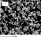
- FIG. 1 is an SEM image of a surface of a substrate layer in one embodiment of the composite of the present invention.
- FIG. 13 is a diagram illustrating the aspect ratio of an elongated region.
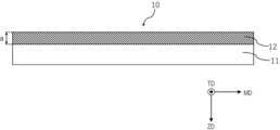
- FIG. 1 is a cross-sectional view showing a schematic diagram of one embodiment of a composite of the present invention.
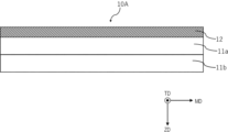
- FIG. 2 is a cross-sectional view illustrating a schematic diagram of another embodiment of the composite of the present invention.
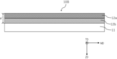
- FIG. 2 is a cross-sectional view illustrating a schematic diagram of another embodiment of the composite of the present invention.
- the composite of the present invention is a composite comprising a foam layer and a base layer formed on at least one surface of the foam layer, the base layer containing an inorganic material, and when the base layer is observed with a scanning electron microscope, the base layer has an elongated region in which a plurality of inorganic particles are connected in a string-like pattern.
- the substrate layer of the present invention contains an inorganic material, and when the substrate layer is observed with a scanning electron microscope, the substrate layer has an elongated region in which a plurality of inorganic particles are connected in a string-like shape (hereinafter, sometimes abbreviated as elongated region).
- elongated region By having the elongated region in the substrate layer, the amount of bleeding components from the substrate layer surface can be reduced.
- Fig. 1 shows a scanning electron microscope (SEM) image of one embodiment of the surface of the substrate layer in the present invention.
- Fig. 1 is a photograph of the surface of the substrate layer containing zeolite, an inorganic substance, observed with a scanning electron microscope (SEM). More specifically, Fig.
- FIG. 1 is an image obtained by mapping Si elements in a field of view while observing the morphology with an energy dispersive X-ray analyzer (EDX) attached to the scanning electron microscope.
- EDX energy dispersive X-ray analyzer
- FIG. 1 a state in which a bright-looking inorganic substance is dispersed in a matrix made of a resin that appears black is confirmed.
- portion X of FIG. 1 a state in which one inorganic particle exists alone is confirmed.
- the portions Y and Z an elongated region in which a plurality of inorganic particles are connected in a string-like manner is confirmed.
- the elongated region is a portion in which a plurality of inorganic particles are connected in approximately one direction.
- the plurality of inorganic particles are preferably three or more inorganic particles, more preferably four or more inorganic particles, and even more preferably five or more inorganic particles.
- the upper limit of the number of inorganic particles to be connected is not particularly limited, but is, for example, 50.
- the elongated region is a roughly rod-shaped region and may have some bent parts, but when the line segment with the longest length among the line segments connecting any two points on the periphery of the elongated region is identified, all of those line segments are deemed to pass through the elongated region.
- the elongated region does not include the portion of the inorganic particles that exists in a branched form from the portion where the inorganic particles are connected in approximately one direction (portion b shown in the figure).
- the aspect ratio of the elongated region is at least 3, preferably at least 4, and more preferably at least 5.
- the upper limit of the aspect ratio is not particularly limited, but is, for example, 50.
- 2 is a schematic diagram of the elongated region indicated by Y in FIG. 1, and the aspect ratio of the elongated region is the ratio of the long axis to the short axis of the elongated region (long axis/short axis).
- the long axis of the elongated region means the longest line segment among the line segments connecting any two points on the periphery of the elongated region.
- the short axis is a line segment connecting two points on the periphery of the elongated region, passing through the midpoint of the long axis and perpendicular to the long axis.
- the presence or absence of the elongated regions can be confirmed by SEM-EDX measurement, and in this case, it is preferable to map elements according to the type of inorganic substance contained.
- the observation of the base layer with a scanning electron microscope may be performed on the portion of the base layer where the inorganic substance is present, and specifically, the surface or cross section of the portion of the base layer where the inorganic substance is present may be measured. For example, when the base layer is formed only of an inorganic particle-containing layer described later, the surface may be observed.
- the number of elongated regions is 2 or more, more preferably 3 or more, and even more preferably 10 or more per observation field of view of 50 ⁇ m ⁇ 50 ⁇ m.
- the area of inorganic-derived elements relative to an observation field of view of 50 ⁇ m ⁇ 50 ⁇ m is, for example, 5% or more, preferably 10% or more, and more preferably 20% or more.
- the above-mentioned elongated regions are observed, and also that multiple branch shapes formed by inorganic particles are observed, as shown in FIG. 1b.
- the branch shapes are shapes in which inorganic particles other than the elongated regions are connected to the inorganic particles that form the elongated regions. In such cases, the amount of bleeding components from the surface of the base layer can be further reduced.
- the method for obtaining a substrate layer having such elongated regions is not particularly limited, but an example is a method using an aqueous emulsion containing inorganic particles, which will be described later. This method contains a high concentration of inorganic matter and allows a thin coating film to be formed on the foam, making it easier to obtain a substrate layer having the elongated regions.
- the substrate layer contains an inorganic substance.
- the elemental analysis of the substrate layer it is preferable that at least one element belonging to the third period is observed.
- elements belonging to the third period include Na, Mg, Al, Si, P, S, Cl, and Ar.
- Al and Si are observed in the substrate layer.
- the inorganic material contained in the base layer is not particularly limited, but is preferably a porous particle.
- porous particles include silica such as mesoporous silica, silica gel, and fumed silica, zeolites such as artificially synthesized zeolites and naturally occurring zeolites, activated carbon, Montlorillonite, hydrotalcite, diatomite, clinker ash, fly ash, aluminum oxide, magnesium oxide, calcium oxide, strontium oxide, barium oxide, titanium oxide, zirconium oxide, aluminum hydroxide, magnesium hydroxide, strontium hydroxide, barium hydroxide, zirconium hydroxide, zirconium phosphate, titanium phosphate, aluminum phosphate, calcium carbonate, metal organic framework MOF, porous crystalline aluminum phosphate ALPO, porous crystalline silicoaluminophosphate SAPO, etc.
- silica, zeolite, aluminum oxide, magnesium oxide, and calcium carbonate are preferred, silica, zeolite, and aluminum oxide are more preferred, and zeolite is even more preferred.
- the inorganic material is preferably particulate, and the average particle size is not particularly limited, but is preferably 0.01 to 100 ⁇ m, more preferably 0.1 to 80 ⁇ m, and even more preferably 0.5 to 20 ⁇ m.
- the average particle size of the inorganic material refers to the cumulative median diameter measured using a particle size distribution diameter measuring device, SEM measurement, etc.
- the base layer contains a resin in addition to the inorganic material described above. More specifically, the base layer preferably includes at least an inorganic particle-containing layer that contains a resin and an inorganic material. The base layer preferably exhibits at least one endothermic peak in a temperature range of 50 to 200° C. as measured by a differential scanning calorimeter (DSC).
- DSC differential scanning calorimeter
- thermoplastic resin examples include thermoplastic elastomers such as olefin-based thermoplastic elastomers (TPO), styrene-based thermoplastic elastomers, ester-based thermoplastic elastomers, and amide-based thermoplastic elastomers, polyolefin-based resins such as polypropylene-based resins (PP), polyethylene-based resins (PE), and poly(1-)butene resins, acrylonitrile-butadiene-styrene (ABS) resins, polycarbonate resins, polyphenylene ether resins, (meth)acrylic resins, polyamide resins, and polyvinyl chloride resins (PVC).
- TPO olefin-based thermoplastic elastomers
- styrene-based thermoplastic elastomers such as polypropylene-based resins (PP), polyethylene-based resins (PE), and poly(1-)butene resins, acrylonit
- the thermoplastic resin is preferably at least one selected from polyolefin-based resins and olefin-based thermoplastic elastomers (TPOs), more preferably polyolefin-based resins, and even more preferably polyethylene-based resins.
- TPOs thermoplastic elastomers
- the resin in the substrate layer is a polyethylene-based resin. This improves the adhesion between the foam layer and the substrate layer.
- thermoplastic elastomer any of blend type, dynamic crosslinking type, and polymerization type can be used.
- olefin-based thermoplastic elastomers include those containing polypropylene as a hard segment and a copolymer having ethylene, propylene, and a small amount of a diene component as necessary as a soft segment.
- copolymers include ethylene-propylene copolymers (EPR) and ethylene-propylene-diene copolymers (EPDM).
- TPO thermoplastic elastomer
- EPR olefin-based thermoplastic elastomer
- Polyethylene resins are not particularly limited, but examples include low-density polyethylene, medium-density polyethylene, high-density polyethylene, linear low-density polyethylene, and ethylene- ⁇ -olefin copolymers whose main component is ethylene, and these may be used alone or in combination of two or more types.
- the composite 10 of the present invention includes a foam layer 11 and a base layer 12 laminated on one surface of the foam layer 11.
- the base layer 12 is an inorganic particle-containing layer that contains a resin and an inorganic substance.
- 3 shows a diagram in which the base layer 12 is laminated on one side of the foam layer 11, but the base layer 12 may be laminated on both sides of the foam layer 11. From the viewpoint of improving moldability and taking into consideration applications as automotive interior materials, a composite in which the base layer 12 is laminated on one side of the foam layer 11 as shown in FIG.
- the foam layer is composed of only one layer, but the foam layer may be multiple layers of two or more layers.
- the foam layer 11 may be a two-layer structure of foam layer 11a and foam layer 11b as shown in FIG. 4.
- the composite 10A of FIG. 4 is a composite in which foam layer 11b, foam layer 11a, and base layer 12 are laminated in this order.
- the substrate layer 12 is shown to be composed of only one layer, but the substrate layer 12 may be composed of two or more layers.
- the substrate layer 12 may be composed of two layers, a first substrate layer 12b and a second substrate layer 12a, as shown in Fig. 5.
- the composite 10B of Fig. 5 is a composite in which the foam layer 11, the first substrate layer 12b, and the second substrate layer 12a are laminated in this order.
- the base layer 12 has multiple layers, at least one of the layers is an inorganic particle-containing layer that contains a resin and an inorganic substance, and the other layers may or may not contain an inorganic substance.
- the second base layer 12a may be a resin layer that does not contain inorganic matter
- the first base layer 12b may be an inorganic particle-containing layer that contains a resin and an inorganic matter.
- the content of inorganic matter in the inorganic particle-containing layer is preferably 70 to 300 parts by mass, and more preferably 100 to 150 parts by mass, per 100 parts by mass of resin.
- the thickness of the inorganic particle-containing layer is not particularly limited, but is preferably 1 to 200 ⁇ m, more preferably 3 to 100 ⁇ m, even more preferably 5 to 50 ⁇ m, and even more preferably 5 to 20 ⁇ m.
- the inorganic particle-containing layer is preferably a coating film, more specifically, a coating film formed from an inorganic particle-containing aqueous emulsion, which will be described later.
- a coating film formed from an inorganic particle-containing aqueous emulsion, which will be described later.
- the base layer may include a resin layer (second base layer) that does not contain inorganic particles.
- the resin layer is a layer made of a resin.
- the resins described as the resin contained in the base layer can be used without any particular limitation, and among them, a polyethylene-based resin or an olefin-based thermoplastic elastomer (TPO) is preferable, and an olefin-based thermoplastic elastomer (TPO) is more preferable.
- the thickness of the resin layer (second substrate layer) that does not contain inorganic particles is not particularly limited, but is preferably 100 to 1000 ⁇ m, and more preferably 300 to 700 ⁇ m.
- the thickness of the substrate layer is not particularly limited, but is, for example, 1 to 1000 ⁇ m, preferably 3 to 100 ⁇ m, more preferably 5 to 50 ⁇ m, and even more preferably 5 to 20 ⁇ m.
- the composite of the present invention includes a foam layer.
- a foam layer By including a foam layer, flexibility, light weight, etc. can be imparted to the composite.
- the foam layer is not particularly limited, and examples thereof include polyolefin resin foam, polystyrene foam, polyurethane foam, phenolic resin foam, urea resin foam, epoxy resin foam, acrylic resin foam, rubber foam, polyvinyl chloride foam, polyamide resin foam, polyimide resin foam, polyvinyl alcohol resin foam, ionomer foam, pyranyl resin foam, and silicone resin foam. These foams can be used alone or in combination of two or more. Among these foams, polyolefin resin foam is preferred, and crosslinked polyolefin resin foam is more preferred.
- the foam layer is formed by foaming a foamable resin composition containing a resin.
- the foam layer is a crosslinked polyolefin resin foam, it is formed by crosslinking and foaming a foamable resin composition containing a polyolefin resin.
- polyolefin resin examples of the polyolefin resin contained in the foamable resin composition include polyethylene-based resin, polypropylene-based resin, ethylene vinyl acetate resin, etc. From the viewpoint of improving the heat resistance and moldability of the resulting crosslinked polyolefin resin foam, the polyolefin resin preferably contains a polypropylene-based resin, and more preferably contains both a polypropylene-based resin and a polyethylene-based resin.
- polypropylene-based resins examples include homopolypropylene, ethylene-propylene random copolymers mainly composed of propylene, and ethylene-propylene block copolymers mainly composed of propylene, and these may be used alone or in combination of two or more. Among these, it is preferable to use an ethylene-propylene random copolymer mainly composed of propylene.
- the term "mainly composed of propylene” means that the content of propylene-derived structural units in the polypropylene-based resin is 75% by mass or more, preferably 90% by mass or more, of the structural units derived from all monomers. The same applies below.
- the melt flow rate (hereinafter, referred to as "MFR") of the polypropylene resin is preferably 70 g/10 min or less, more preferably 50 g/10 min or less, and even more preferably 25 g/10 min or less.
- the lower limit of the MFR is usually 0.1 g/10 min.
- the MFR of the polypropylene resin is a value measured in accordance with JIS K 7210 under conditions of a temperature of 230° C. and a load of 21.2 N.
- the polyethylene resin is not particularly limited, but examples thereof include low-density polyethylene, medium-density polyethylene, high-density polyethylene, linear low-density polyethylene, ethylene- ⁇ -olefin copolymers mainly composed of ethylene, etc., which may be used alone or in combination of two or more.
- linear low-density polyethylene is preferred.
- the density of the linear low density polyethylene is preferably 0.900 to 0.925 g/cm 3 , and more preferably 0.902 to 0.922 g/cm 3 .
- the MFR of the polyethylene resin is preferably from 0.5 to 70 g/10 min, and more preferably from 1.5 to 50 g/10 min.
- the MFR of the polyethylene resin is a value measured in accordance with JIS K 7210 under conditions of a temperature of 190° C. and a load of 21.2 N.
- the foamable resin composition may further contain a resin other than the polypropylene-based resin, specifically, a polyolefin-based resin other than the polypropylene-based resin such as a polyethylene-based resin, an olefin-based elastomer, etc.
- the total content of the polyolefin-based resin other than the polypropylene-based resin and the olefin-based elastomer relative to the total amount of resin contained in the foamable resin composition is preferably 10 mass% or more, more preferably 20 mass% or more, even more preferably 25 mass% or more, and also preferably 50 mass% or less, more preferably 45 mass% or less, even more preferably 40 mass% or less.
- the olefin-based elastomer include ethylene-propylene-diene rubber (EPDM), ethylene-propylene rubber (EPM), olefin-based thermoplastic elastomer, etc.
- the foamable resin composition may contain a resin other than the polyolefin resin and the olefin-based elastomer.
- the foamable resin composition preferably contains an antioxidant. By containing an antioxidant, oxidative deterioration of the polyolefin resin can be suppressed.
- the foamable resin composition preferably contains 0.1 to 5.0 parts by mass, more preferably 0.5 to 4.0 parts by mass, of the antioxidant per 100 parts by mass of the resin contained in the foamable resin composition. By using 0.5 parts by mass or more of the antioxidant per 100 parts by mass of the resin, the oxidative degradation of the polyolefin resin can be further suppressed, and the bleeding out of oxidative degradation products from the crosslinked polyolefin resin foam can be reduced. Also, by using 5.0 parts by mass or less of the antioxidant per 100 parts by mass of the resin, the bleeding out of excess antioxidant can be suppressed.
- the type of antioxidant is not particularly limited, and examples thereof include phenol-based antioxidants, sulfur-based antioxidants, phosphorus-based antioxidants, amine-based antioxidants, etc. Among these, at least one selected from phenol-based antioxidants and phosphorus-based antioxidants is preferred, and among these, phenol-based antioxidants are more preferred from the viewpoints of antioxidant action and compatibility with resins.
- phenol-based antioxidant examples include 2,6-di-tert-butyl-p-cresol, n-octadecyl-3-(3,5-di-tert-butyl-4-hydroxyphenyl)propionate, 2-tert-butyl-6-(3-tert-butyl-2-hydroxy-5-methylbenzyl)-4-methylphenylacrylate, tetrakis[methylene-3-(3,5-di-tert-butyl-4-hydroxyphenyl)propionate]methane, etc.
- 2,6-di-tert-butyl-p-cresol is preferred.
- the antioxidants may be used alone or in combination of two or more kinds.
- the foamable resin composition preferably contains a crosslinking aid.
- the content of the crosslinking aid in the foamable resin composition is preferably 2.0 to 5.0 parts by mass, more preferably 2.5 to 4.7 parts by mass, per 100 parts by mass of the resin contained in the foamable resin composition.
- crosslinking aid examples include polyfunctional (meth)acrylate compounds such as trifunctional (meth)acrylate compounds and bifunctional (meth)acrylate compounds, compounds having three functional groups in one molecule, etc.
- Other crosslinking aids include compounds having two functional groups in one molecule such as divinylbenzene, diallyl phthalate, diallyl terephthalate, diallyl isophthalate, ethylvinylbenzene, lauryl methacrylate, stearyl methacrylate, etc.
- trifunctional (meth)acrylate compounds include trimethylolpropane trimethacrylate and trimethylolpropane triacrylate.
- bifunctional (meth)acrylate compounds examples include 1,6-hexanediol dimethacrylate, 1,9-nonanediol dimethacrylate, 1,10-decanediol dimethacrylate, and neopentyl glycol dimethacrylate.
- compounds having three functional groups in one molecule include trimellitic acid triallyl ester, 1,2,4-benzenetricarboxylic acid triallyl ester, and triallyl isocyanurate.
- the crosslinking assistants may be used alone or in combination of two or more. Among these, polyfunctional (meth)acrylate compounds are preferred, bifunctional (meth)acrylate compounds are more preferred, and 1,9-nonanediol dimethacrylate is even more preferred.
- Methods for foaming the foamable resin composition include a chemical foaming method and a physical foaming method.
- the chemical foaming method is a method in which bubbles are formed by gas generated by thermal decomposition of a compound added to the foamable resin composition
- the physical foaming method is a method in which a low-boiling point liquid (foaming agent) is impregnated into the foamable resin composition, and then the foaming agent is volatilized to form cells.
- the foaming method is not particularly limited, but the chemical foaming method is preferred.
- a thermally decomposable foaming agent is preferably used, for example, an organic or inorganic chemical foaming agent having a decomposition temperature of about 140 to 270° C.
- organic blowing agents include azo compounds such as ammonium carbonate, ammonium hydrogen carbonate, ammonium nitrite, azodicarbonamide, and azobisisobutyronitrile, nitroso compounds such as N,N'-dinitrosopentamethylenetetramine, hydrazine derivatives such as hydrazodicarbonamide, 4,4'-oxybis(benzenesulfonylhydrazide), and toluenesulfonylhydrazide, and semicarbazide compounds such as toluenesulfonylsemicarbazide.
- inorganic foaming agents examples include sodium carbonate, sodium hydrogen carbonate, metal azodicarboxylates (eg, barium azodicarboxylate), sodium borohydride, and anhydrous monosodium citrate.
- metal azodicarboxylates eg, barium azodicarboxylate
- sodium borohydride e.g., sodium borohydride
- anhydrous monosodium citrate e.g., sodium carbonate, sodium hydrogen carbonate, metal azodicarboxylates (eg, barium azodicarboxylate), sodium borohydride, and anhydrous monosodium citrate.
- azo compounds and nitroso compounds are preferred, azodicarbonamide, azobisisobutyronitrile and N,N'-dinitrosopentamethylenetetramine are more preferred, and azodicarbonamide is particularly preferred.
- the foaming agents may be used alone or in combination of two or more kinds.
- the amount of the foaming agent added to the foamable resin composition is preferably 1 to 20 parts by mass, more preferably 2 to 15 parts by mass, and even more preferably 3 to 12 parts by mass, per 100 parts by mass of the polyolefin resin, from the viewpoint of easily setting the expansion ratio of the foam in the range described below.
- the foamable resin composition may contain additives generally used in foams, such as a heat stabilizer, a colorant, a flame retardant, an antistatic agent, a filler, a rust inhibitor, and a decomposition temperature adjuster, as necessary.
- additives generally used in foams such as a heat stabilizer, a colorant, a flame retardant, an antistatic agent, a filler, a rust inhibitor, and a decomposition temperature adjuster, as necessary.
- the degree of crosslinking of the foam layer of the present invention is preferably 30 to 60% by mass.
- the degree of crosslinking is 30 to 60% by mass, the mechanical strength, flexibility, and moldability of the foam can be improved in a well-balanced manner.
- the degree of crosslinking of the crosslinked polyolefin resin foam of the present invention is more preferably 33 to 57% by mass, and even more preferably 35 to 55% by mass.
- the degree of crosslinking can be measured by the following method. A test piece of about 100 mg is taken from the foam layer, and the mass A (mg) of the test piece is precisely weighed.
- the thickness of the foam layer is not particularly limited, but is preferably 1 to 5 mm, more preferably 1.2 to 4 mm, and further preferably 1.5 to 3.5 mm.
- the method for producing the composite of the present invention is not particularly limited, but examples thereof include a method comprising a step (A) of producing a foam layer and a step (B) of forming a base layer on at least one surface of the foam layer produced in step (A).
- Step 1 is a step of processing the foamable resin composition into a sheet shape to produce a foamable sheet.
- the foamable resin composition is kneaded using a kneader such as a Banbury mixer or a pressure kneader, and then continuously extruded using an extruder, a calendar, conveyor belt casting, or the like to produce a foamable sheet.
- the temperature at which the foamable resin composition is kneaded is preferably 170 to 210°C, more preferably 175 to 205°C.
- Step (B) is a step of forming a base layer on at least one surface of the foam layer produced in step (A).
- a method for forming the substrate layer on at least one surface of the foam layer a method using an aqueous emulsion for forming an inorganic particle-containing layer in the substrate layer can be mentioned.
- a base layer can be formed on at least one surface of the foam layer.
- Step 4) A step of preparing an aqueous emulsion.
- Step 5) A step of dispersing inorganic particles in the aqueous emulsion to prepare an aqueous emulsion containing inorganic particles.
- Step 6) A step of applying the aqueous emulsion containing inorganic particles to at least one surface of the foam layer and drying the emulsion to form an inorganic particle-containing layer.
- Step 4 is a step of preparing a water-based emulsion.
- the aqueous emulsion contains at least water and resin particles.
- the resin particles are of the same type as the resin contained in the inorganic particle-containing layer to be formed. That is, when the resin contained in the inorganic particle-containing layer is a polyethylene-based resin, the resin particles contained in the aqueous emulsion are polyethylene-based resin particles.
- the aqueous emulsion is preferably obtained by emulsion polymerization of monomers for producing resin particles.
- the monomers for producing resin particles are, for example, ethylene monomers when the resin particles are polyethylene resins, and ⁇ -olefin monomers having about 3 to 10 carbon atoms, which are used as needed.
- the aqueous emulsion can be produced by adding a surfactant as an emulsifier, monomers, and a pH adjuster to a dispersion medium whose main component is water (for example, a dispersion medium containing 90% or more by mass of water, preferably a dispersion medium consisting of water), and emulsion polymerizing the monomers while stirring.
- additives such as a polymerization initiator, a chain transfer agent, and a stabilizer may be added as needed.
- Step 5 inorganic particles are dispersed in the aqueous emulsion prepared as described above to obtain an aqueous emulsion containing inorganic particles.
- the inorganic particles dispersed in the aqueous emulsion are the same type of inorganic material as that contained in the inorganic particle-containing layer to be formed.
- the amount of inorganic particles per 100 parts by mass of resin particles in the inorganic particle-containing aqueous emulsion is the same as the amount of inorganic matter per 100 parts by mass of resin in the inorganic particle-containing layer described above.
- Step 6 the inorganic particle-containing aqueous emulsion obtained as described above is applied to at least one surface of the foam layer and dried to form an inorganic particle-containing layer.
- the method for applying the inorganic particle-containing aqueous emulsion is not particularly limited, and various coaters may be used, such as a bar coater, a comma coater, a gravure coater, a dip coater, a roll coater, a spin coater, a flow coater, a knife coater, and a spray coater.
- the temperature during drying is, for example, 30 to 150°C, and preferably 60 to 120°C.
- a composite body of a foam layer and a base layer laminated on at least one surface of the foam layer is obtained by carrying out the above steps 4 to 6.
- the base layer is composed of a single layer of an inorganic particle-containing layer, and is a coating film of an inorganic particle-containing aqueous emulsion.
- an inorganic particle-containing aqueous emulsion it becomes easier to obtain a base layer in which the above-mentioned elongated regions in which a plurality of inorganic particles are linked together in a string-like pattern are observed.
- the method of using an aqueous emulsion containing inorganic particles is also preferred in that the VOC (volatile organic compounds) of the obtained composite is reduced.
- the method of forming the inorganic particle-containing layer is described by describing the "step of preparing an aqueous emulsion” and the “step of preparing an aqueous emulsion containing inorganic particles", but the "aqueous emulsion” and the “aqueous emulsion containing inorganic particles” can be commercially available products as necessary.
- a resin layer (such as a resin film) that does not contain inorganic particles may be laminated to the surface of the inorganic particle-containing layer formed on at least one side of the foam layer as described above.
- the lamination method and process are not particularly limited, but may be a method of applying heat and pressure using a press or the like to achieve thermocompression bonding, or a method using an adhesive or pressure sensitive adhesive.
- the composite of the present invention can be molded by various molding methods such as vacuum molding and used as a heat insulating material, a cushioning material, etc.
- the composite of the present invention can be suitably used as an automotive interior material such as a ceiling material, a door, an instrument panel, etc.
- the surface of the substrate layer of the composite was measured by a SEM-EDX device ("JSM-IT100" manufactured by JEOL Ltd.) to measure the distribution state of the inorganic substances and the types of elements in the substrate layer.
- the measurement conditions for SEM-EDX were as follows: Observation magnification: 2000 times Viewing angle: 190 ⁇ m ⁇ 86 ⁇ m Observation field: 50 ⁇ m x 50 ⁇ m Acceleration voltage: 10 kV WD: 10mm
- the above-mentioned viewing angle corresponds to the size of the SEM photograph obtained, and the observation field corresponds to the field in which the distribution state of the inorganic substances is observed.
- the inorganic matter contained in the base material layer was used as a measurement sample, and the presence or absence of pores and their diameters were determined by measuring the nitrogen adsorption/desorption isotherm using a "BELSORP-mini" made by Bell Japan.
- the substrate layer was used as a sample and heated at a rate of 10°C/min from 25 to 250°C under a nitrogen flow condition of 40 mL/min using a differential scanning calorimeter (DSC, Yamato Scientific Co., Ltd. "DSC7020") to check for the presence or absence of an endothermic peak in the temperature range of 50 to 200°C.
- DSC differential scanning calorimeter
- ⁇ Presence or absence of bleeding on the surface of the base layer> The composites produced in each of the Examples and Comparative Examples were heated at 80°C, 100°C, and 120°C for 24 hours, and then the presence or absence of bleeding (presence or absence of bleed-out) on the surface of the base layer was visually evaluated. A judgment of whether or not the condition was present was made based on the following evaluation items. Yes: Visual check: gloss, discoloration, and stickiness are observed. No: Visual check: gloss, discoloration, and stickiness are not observed.
- Polypropylene resin (2) random PP, manufactured by Sumitomo Chemical Co., Ltd., trade name "AD571", density 0.90 g/cm 3 , MFR 0.5 g/10 min (230° C.)
- LLDPE Linear low density polyethylene, manufactured by Prime Polymer Co., Ltd., trade name "UltraZex 1020L”, density 0.91 g/cm 3 , MFR 2.0 g/10 min (190° C.)
- TPO Olefin-based thermoplastic elastomer, manufactured by Basell, trade name "Softell CA 02 A”, MFR 0.6 g/10 min (230° C.)
- EPDM Olefin-based elastomer, manufactured by Mitsui Chemicals, Inc., product name "3045"
- Foaming agent azodicarbonamide, manufactured by Otsuka Chemical Co., Ltd., trade name "SO-L”, decomposition temperature: 197°C, average particle size: 3.2 ⁇ m
- Phenolic antioxidant
- silica (SiO 2 ) was dispersed in an aqueous emulsion in which polyethylene resin particles were dispersed to prepare an inorganic particle-containing aqueous emulsion (1).
- the amount of silica (SiO 2 ) per 100 parts by mass of polyethylene resin particles in the inorganic particle-containing aqueous emulsion (1) was 95 parts by mass.
- the average particle size of the silica (SiO 2 ) used was 9 ⁇ m .
- Inorganic particle-containing aqueous emulsion (2) Magnesium oxide (MgO) was dispersed in an aqueous emulsion in which polyethylene resin particles were dispersed to prepare inorganic particle-containing aqueous emulsion (2).
- the amount of magnesium oxide (MgO) per 100 parts by mass of polyethylene resin particles in inorganic particle-containing aqueous emulsion (2) was 80 parts by mass.
- the average particle diameter of the magnesium oxide (MgO) used was 5 ⁇ m.
- Inorganic particle-containing aqueous emulsion (3) Aluminum oxide (Al 2 O 3 ) was dispersed in an aqueous emulsion in which polyethylene resin particles were dispersed to prepare an inorganic particle-containing aqueous emulsion (3).
- the amount of aluminum oxide (Al 2 O 3 ) per 100 parts by mass of polyethylene resin particles in the inorganic particle-containing aqueous emulsion (3) was 110 parts by mass.
- the average particle size of the aluminum oxide (Al 2 O 3 ) used was 7.2 ⁇ m.
- Inorganic particle-containing aqueous emulsion (4) Calcium carbonate (CaCO 3 ) was dispersed in an aqueous emulsion in which polyethylene resin particles were dispersed to prepare an inorganic particle-containing aqueous emulsion (4).
- the amount of calcium carbonate (CaCO 3 ) per 100 parts by mass of polyethylene resin particles in the inorganic particle-containing aqueous emulsion (4) was 100 parts by mass.
- the average particle size of the calcium carbonate (CaCO 3 ) used was 9 ⁇ m.
- Inorganic particle-containing aqueous emulsion (5) ...Zeolite was dispersed in an aqueous emulsion in which polyethylene resin particles were dispersed to prepare inorganic particle-containing aqueous emulsion (5).
- the amount of zeolite per 100 parts by mass of polyethylene resin particles in inorganic particle-containing aqueous emulsion (5) was 120 parts by mass.
- the average particle size of the zeolite used was 7 ⁇ m.
- Inorganic particle-containing aqueous emulsion (6) Aluminum oxide (Al 2 O 3 ) was dispersed in an aqueous emulsion in which polyethylene resin particles were dispersed to prepare an inorganic particle-containing aqueous emulsion (6).
- the amount of aluminum oxide (Al 2 O 3 ) per 100 parts by mass of polyethylene resin particles in the inorganic particle-containing aqueous emulsion (6) was 10 parts by mass.
- the average particle diameter of the aluminum oxide (Al 2 O 3 ) used was 7.2 ⁇ m.
- Inorganic particle-containing aqueous emulsion (7) ...Zeolite was dispersed in an aqueous emulsion in which polyethylene resin particles were dispersed to prepare inorganic particle-containing aqueous emulsion (7).
- the amount of zeolite per 100 parts by mass of polyethylene resin particles in inorganic particle-containing aqueous emulsion (7) was 10 parts by mass.
- the average particle size of the zeolite used was 7 ⁇ m.
- Example 1 (Production of foam layer) A foamable resin composition obtained by mixing polypropylene resin (2), LLDPE, phenolic antioxidant, crosslinking aid, and foaming agent in the ratio shown in Table 1 was melt-kneaded at 180°C by a single screw extruder to obtain a foamable sheet. Both sides of the foamable sheet were irradiated with ionizing radiation (electron beam) at 2.0 Mrad at an acceleration voltage of 1000 kV to obtain a crosslinked foamable sheet. Thereafter, the crosslinked foamable sheet was fed into a vertical hot air type foaming furnace with an internal temperature of 250°C, and heated and foamed while stretching to obtain a crosslinked polyolefin resin foam having a thickness of 2.5 mm.
- ionizing radiation electron beam
- the inorganic particle-containing aqueous emulsion (1) was applied to one side of the crosslinked polyolefin resin foam prepared as described above using a roll coater, and then dried at a drying temperature of 100° C. to form a base layer made of an inorganic particle-containing layer.
- the thickness of the base layer made of an inorganic particle-containing layer was 10 ⁇ m. In this manner, a composite of a crosslinked polyolefin resin foam/an inorganic particle-containing layer (base layer) was obtained.
- Example 2 A crosslinked polyolefin resin foam was obtained in the same manner as in Example 1, except that the composition of the foamable resin composition was changed as shown in Table 1. Then, a composite was obtained in the same manner as in Example 1, except that the type of inorganic particle-containing aqueous emulsion was changed as follows. In Example 2, inorganic particle-containing aqueous emulsion (2) was used, in Example 3, inorganic particle-containing aqueous emulsion (3), in Example 4, inorganic particle-containing aqueous emulsion (4), and in Examples 5 to 7, inorganic particle-containing aqueous emulsion (5) were used.
- Example 1 A crosslinked polyolefin resin foam was obtained in the same manner as in Example 1. Then, the types of inorganic particle-containing aqueous emulsions were changed as follows, and a composite was obtained in the same manner as in Example 1. In Comparative Example 1, inorganic particle-containing aqueous emulsion (6) was used.
- Example 2 A crosslinked polyolefin resin foam was obtained in the same manner as in Example 1. Next, an aqueous emulsion (containing no inorganic substances) was applied to the crosslinked polyolefin foam using a roll coater, and other treatments were carried out in the same manner as in Example 1 to obtain a composite.
- Example 3 A crosslinked polyolefin resin foam was obtained in the same manner as in Example 5. Then, the types of inorganic particle-containing aqueous emulsions were changed as follows, and a composite was obtained in the same manner as in Example 5. In Comparative Example 3, inorganic particle-containing aqueous emulsion (7) was used.
- the composites of Examples 1 to 7 were composites including a foam layer and a base layer containing an inorganic material.
- a base layer was observed with a scanning electron microscope, elongated regions in which a plurality of inorganic particles were linked together in a string-like pattern were observed, and no bleeding from the surface of the base layer was confirmed.
- the composites of Comparative Examples 1 and 3 although an inorganic substance was contained in the base layer, no elongated regions were confirmed when the base layer was observed with a scanning electron microscope.
- the base layer of the composite of Comparative Example 2 did not contain an inorganic substance.
- the composites of Comparative Examples 1 to 3 did not satisfy the specified requirements of the present invention, and as a result, bleeding from the surface of the base layer was confirmed.
Landscapes
- Chemical & Material Sciences (AREA)
- Health & Medical Sciences (AREA)
- Chemical Kinetics & Catalysis (AREA)
- Medicinal Chemistry (AREA)
- Polymers & Plastics (AREA)
- Organic Chemistry (AREA)
- Engineering & Computer Science (AREA)
- Materials Engineering (AREA)
- Laminated Bodies (AREA)
Abstract
本発明の複合体は、発泡体層と、該発泡体層の少なくとも一方の面に形成された基材層とを備え、前記基材層は無機物を含有し、前記基材層を走査型電子顕微鏡で観察したときに、複数の無機物粒子が数珠つなぎ状に連結された細長状の領域が観察される複合体である。 本発明によれば、発泡体層を備える複合体であって、ブリード成分量の少ない複合体を提供することができる。
Description
本発明は、発泡体層と基材層とを備える複合体に関する。
発泡体は、柔軟性、軽量性などに優れるため、車載用途、電子機器用途、民生機器、住宅建材など様々な分野で使用されている。
発泡体は単層で用いてもよいが、加工性、機能付与の観点などから、発泡体に樹脂フィルムなどの非発泡層を積層した積層体として用いることも知られている。
例えば、特許文献1には、変性PPE系樹脂を基材樹脂とする発泡層の両面に、熱可塑性樹脂を基材樹脂とする非発泡層が積層された発泡積層シートの、片面に異音防止層が積層され、その反対面に、表皮材が多層ホットメルト接着剤を介して積層されてなることを特徴とする、自動車内装材用発泡積層シートに関する発明が開示されている。そして、優れた耐薬品性を付与した自動車内装材用基材および自動車内装材を提供することができることが記載されている。
発泡体は単層で用いてもよいが、加工性、機能付与の観点などから、発泡体に樹脂フィルムなどの非発泡層を積層した積層体として用いることも知られている。
例えば、特許文献1には、変性PPE系樹脂を基材樹脂とする発泡層の両面に、熱可塑性樹脂を基材樹脂とする非発泡層が積層された発泡積層シートの、片面に異音防止層が積層され、その反対面に、表皮材が多層ホットメルト接着剤を介して積層されてなることを特徴とする、自動車内装材用発泡積層シートに関する発明が開示されている。そして、優れた耐薬品性を付与した自動車内装材用基材および自動車内装材を提供することができることが記載されている。
ところで、発泡体や、発泡体と非発泡体との複合体においては、含有される樹脂の低分子量成分や、各種添加剤に起因するブルームやブリードが生じる場合があり、表面のべたつきや使用対象製品の汚染などの原因となる。このようなことから、近年、ブリード成分量の少ない発泡体製品が強く求められている。
そこで本発明は、発泡体層を備える複合体であって、ブリード成分量の少ない複合体を提供することを課題とする。
そこで本発明は、発泡体層を備える複合体であって、ブリード成分量の少ない複合体を提供することを課題とする。
本発明者らは、上記課題を解決するため、鋭意検討した。その結果、発泡体層と、該発泡体層の少なくとも一方の面に形成された基材層とを備えた複合体であって、前記基材層は無機物を含有し、前記基材層を走査型電子顕微鏡で観察したときに、複数の無機物粒子が数珠つなぎ状に連結された細長状の領域を有する複合体により、上記課題を解決できることを見出し、以下の本発明を完成させた。
すなわち、本発明は、以下の[1]~[6]を提供するものである。
すなわち、本発明は、以下の[1]~[6]を提供するものである。
[1]発泡体層と、該発泡体層の少なくとも一方の面に形成された基材層とを備えた複合体であって、前記基材層は無機物を含有し、前記基材層を走査型電子顕微鏡で観察したときに、複数の無機物粒子が数珠つなぎ状に連結された細長状の領域が観察される、複合体。
[2]前記基材層を走査型電子顕微鏡で観察したときに、無機物粒子により形成された複数の枝形状が観察される、上記[1]に記載の複合体。
[3]前記基材層の元素分析において、第三周期に属する元素が少なくとも1種観測される、上記[1]又は[2]に記載の複合体
[4]元素分析でAlとSiとが観測される、上記[1]~[3]のいずれかに記載の複合体。
[5]前記基材層は樹脂を含有する、上記[1]~[4]のいずれかに記載の複合体。
[6]前記基材層は示差走査熱量計(DSC)による測定で、50~200℃の温度域で少なくとも1つ吸熱ピークを示す、上記[1]~[5]のいずれかに記載の複合体。
[2]前記基材層を走査型電子顕微鏡で観察したときに、無機物粒子により形成された複数の枝形状が観察される、上記[1]に記載の複合体。
[3]前記基材層の元素分析において、第三周期に属する元素が少なくとも1種観測される、上記[1]又は[2]に記載の複合体
[4]元素分析でAlとSiとが観測される、上記[1]~[3]のいずれかに記載の複合体。
[5]前記基材層は樹脂を含有する、上記[1]~[4]のいずれかに記載の複合体。
[6]前記基材層は示差走査熱量計(DSC)による測定で、50~200℃の温度域で少なくとも1つ吸熱ピークを示す、上記[1]~[5]のいずれかに記載の複合体。
本発明によれば、発泡体層を備える複合体であって、ブリード成分量の少ない複合体を提供することができる。
以下、本発明について実施形態を用いて詳細に説明する。
[複合体]
本発明の複合体は、発泡体層と、該発泡体層の少なくとも一方の面に形成された基材層とを備えた複合体であって、前記基材層は無機物を含有し、前記基材層を走査型電子顕微鏡で観察したときに、複数の無機物粒子が数珠つなぎ状に連結された細長状の領域を有する、複合体である。
[複合体]
本発明の複合体は、発泡体層と、該発泡体層の少なくとも一方の面に形成された基材層とを備えた複合体であって、前記基材層は無機物を含有し、前記基材層を走査型電子顕微鏡で観察したときに、複数の無機物粒子が数珠つなぎ状に連結された細長状の領域を有する、複合体である。
<基材層>
本発明の基材層は、無機物を含有し、該基材層を走査型電子顕微鏡で観察したときに、複数の無機物粒子が数珠つなぎ状に連結された細長状の領域(以下細長状領域と略記する場合もある)を有する。このように、基材層に細長状領域を有することで、基材層表面からのブリード成分量を低減することができる。
図1には、本発明における基材層表面の一実施形態の走査型電子顕微鏡(SEM)画像を示している。図1は、無機物であるゼオライトを含む基材層の表面を走査型電子顕微鏡(SEM)で観察したときの写真である。より詳細には、図1は走査型電子顕微鏡に付属のエネルギー分散型X線分析装置(EDX)で、形態を観察しながら、その視野に対してSi元素のマッピングを行ったときの画像である。
図1には、黒色に見える樹脂からなるマトリックスに、明るく見える無機物が分散している状態が確認されている。図1のXの部分には1つの無機物粒子が単独で存在している状態が確認されている。一方でY及びZの部分には、複数の無機物粒子が数珠つなぎ状に連結された細長状の領域が確認されている。該細長状領域とは、複数の無機物粒子が略一方向に連結された部分である。前記複数の無機物粒子とは、好ましくは3つ以上の無機物粒子であり、より好ましくは4つ以上の無機物粒子であり、さらに好ましくは5つ以上の無機物粒子である。なお、連結される無機物粒子の数の上限値は特に限定されないが、例えば50である。
本発明の基材層は、無機物を含有し、該基材層を走査型電子顕微鏡で観察したときに、複数の無機物粒子が数珠つなぎ状に連結された細長状の領域(以下細長状領域と略記する場合もある)を有する。このように、基材層に細長状領域を有することで、基材層表面からのブリード成分量を低減することができる。
図1には、本発明における基材層表面の一実施形態の走査型電子顕微鏡(SEM)画像を示している。図1は、無機物であるゼオライトを含む基材層の表面を走査型電子顕微鏡(SEM)で観察したときの写真である。より詳細には、図1は走査型電子顕微鏡に付属のエネルギー分散型X線分析装置(EDX)で、形態を観察しながら、その視野に対してSi元素のマッピングを行ったときの画像である。
図1には、黒色に見える樹脂からなるマトリックスに、明るく見える無機物が分散している状態が確認されている。図1のXの部分には1つの無機物粒子が単独で存在している状態が確認されている。一方でY及びZの部分には、複数の無機物粒子が数珠つなぎ状に連結された細長状の領域が確認されている。該細長状領域とは、複数の無機物粒子が略一方向に連結された部分である。前記複数の無機物粒子とは、好ましくは3つ以上の無機物粒子であり、より好ましくは4つ以上の無機物粒子であり、さらに好ましくは5つ以上の無機物粒子である。なお、連結される無機物粒子の数の上限値は特に限定されないが、例えば50である。
細長状領域は、略棒状の領域であり、多少折れ曲がった部分があってもよいが、細長状領域の外周部の任意の2点を結ぶ線分の中で最大長さとなる線分を特定した場合に、その線分はすべて細長状領域を通るものとする。
細長状領域には、無機物粒子が略一方向に連結された部分から、枝分かれ状に存在する無機物粒子の部分(図で示すbの部分)は含まないこととする。
細長状領域には、無機物粒子が略一方向に連結された部分から、枝分かれ状に存在する無機物粒子の部分(図で示すbの部分)は含まないこととする。
また、細長状領域はそのアスペクト比が、3以上であり、好ましくは4以上であり、より好ましくは5以上である。アスペクト比の上限値は特に限定されないが、例えば50である。
図2には、図1のYで示す細長状領域を模式的に示しているが、細長状領域のアスペクト比とは、細長状領域の短径に対する長径の比(長径/短径)である。細長状領域の長径は、細長状領域の外周部の任意の2点を結ぶ線分の中で最大長さとなる線分を意味する。また、短径は、細長状領域の外周部の2点を結ぶ線分であって、長径の中点を通り、かつ長径に垂直な線分である。
図2には、図1のYで示す細長状領域を模式的に示しているが、細長状領域のアスペクト比とは、細長状領域の短径に対する長径の比(長径/短径)である。細長状領域の長径は、細長状領域の外周部の任意の2点を結ぶ線分の中で最大長さとなる線分を意味する。また、短径は、細長状領域の外周部の2点を結ぶ線分であって、長径の中点を通り、かつ長径に垂直な線分である。
細長状領域の有無は、上記のように説明した通り、SEM-EDXの測定により確認でき、この際、含有される無機物の種類に応じた元素でマッピングするとよい。
なお、基材層の走査型電子顕微鏡による観察(SEM-EDX測定による元素のマッピング)は、基材層における無機物が存在する部分について行えばよく、具体的には、基材層における無機物が存在する部分の表面又は断面を測定するとよい。例えば、基材層が、後述する無機粒子含有層のみで形成されている場合は、その表面を観察するとよい。
なお、基材層の走査型電子顕微鏡による観察(SEM-EDX測定による元素のマッピング)は、基材層における無機物が存在する部分について行えばよく、具体的には、基材層における無機物が存在する部分の表面又は断面を測定するとよい。例えば、基材層が、後述する無機粒子含有層のみで形成されている場合は、その表面を観察するとよい。
基材層は、SEM-EDX測定を行った際に、細長状領域の数が、観察視野50μm×50μmあたり、好ましくは2個以上であり、より好ましくは3個以上であり、さらに好ましく10個以上である箇所を有することが好ましい。
また、基材層は、SEM-EDX測定を行った際に、観察視野50μm×50μmに対する、無機物由来の元素の面積が、例えば5%以上であり、好ましくは10%以上であり、より好ましくは20%以上である箇所を有することが好ましい。
また、基材層は、SEM-EDX測定を行った際に、観察視野50μm×50μmに対する、無機物由来の元素の面積が、例えば5%以上であり、好ましくは10%以上であり、より好ましくは20%以上である箇所を有することが好ましい。
また、基材層の上記SEM観察において、上記した細長状領域が観察されるとともに、図1のbに示すように、無機物粒子により形成された複数の枝形状が観察されることが好ましい。枝形状は、細長状領域を形成する無機物粒子から、該細長状領域とは別の無機粒子が連結されている形状である。このような場合、基材層表面からのブリード成分量をより低減することができる。
このような細長状領域を有する基材層を得る方法は特に限定されないが、後述する無機粒子含有水系エマルジョンを用いる方法が挙げられる。この方法では、無機物を高濃度に含み、かつ厚みの薄い塗布膜を発泡体上に形成できるため、上記細長状領域を有する基材層を得やすくなる。
<無機物>
基材層は、無機物を含有する。基材層の元素分析において、第三周期に属する元素が少なくとも1種観測されることが好ましい。ここで第三周期に属する元素としては、Na、Mg、Al、Si、P、S、Cl、Arが挙げられるが。これらの中でも、基材層において、Al及びSiが観測されることが好ましい。基材層にAl及びSiが含まれることで、樹脂と無機物との相互作用などを通じて基材層表面のブリード成分量を低減しやすくなる。なお、元素分析は、SEM-EDXで行うことができる。
基材層は、無機物を含有する。基材層の元素分析において、第三周期に属する元素が少なくとも1種観測されることが好ましい。ここで第三周期に属する元素としては、Na、Mg、Al、Si、P、S、Cl、Arが挙げられるが。これらの中でも、基材層において、Al及びSiが観測されることが好ましい。基材層にAl及びSiが含まれることで、樹脂と無機物との相互作用などを通じて基材層表面のブリード成分量を低減しやすくなる。なお、元素分析は、SEM-EDXで行うことができる。
基材層に含まれる無機物は、特に限定されないが、好ましくは多孔質粒子である。多孔質粒子には、例えば、メソポーラスシリカ、シリカゲル、ヒュームドシリカ等のシリカ、人工合成ゼオライト、天然産生ゼオライト等のゼオライト、活性炭、モンロリロナイト、ハイドロタルサイト、ダイアトマイト、クリンカアッシュ、フライアッシュ、酸化アルミニウム、酸化マグネシウム、酸化カルシウム、酸化ストロンチウム、酸化バリウム、酸化チタニウム,酸化ジルコニウム、水酸化アルミニウム、水酸化マグネシウム、水酸化ストロンチウム、水酸化バリウム、水酸化ジルコニウム、リン酸ジルコニウム、リン酸チタン、リン酸アルミニウム、炭酸カルシウム、金属有機構造体MOF、多孔質結晶性リン酸アルミニウムALPO、多孔質結晶性シリコアルミノリン酸塩SAPO等が挙げられる。これらは1種を単独で使用してもよく、2種以上を混合して使用してもよいし、上記に示した化合物が積層した粒子や,鋳型として使用して合成したコアシェル型粒子,中空粒子,凝集した粒子やアロイ状の融着体を使用してもよい。これらは1種を単独で使用してもよく、2種以上を混合して使用してもよい。これらの中では、シリカ、ゼオライト、酸化アルミニウム、酸化マグネシウム、炭酸カルシウムが好ましく、シリカ、ゼオライト、酸化アルミニウムがより好ましく、ゼオライトがさらに好ましい。
無機物は粒子状であることが好ましく、その平均粒子径は、特に限定されないが、好ましくは0.01~100μmであり、より好ましくは0.1~80μmであり、さらに好ましくは0.5~20μmである。なお、無機物の平均粒子径は、粒度分布径測定器やSEM測定等を用いて測定した累積中位径を意味する。
<樹脂>
基材層は、上記した無機物以外に、樹脂を含有する。より詳細には、基材層は、樹脂及び無機物を含有する無機粒子含有層を少なくとも備えることが好ましい。
基材層は、示差走査熱量計(DSC)による測定で、50~200℃の温度域で少なくとも1つ吸熱ピークを示すことが好ましい。このような熱的な性質を示す樹脂と、上述した無機物とを組み合わせることで、基材層の表面のブリード物を低減しやすくなる。
上記樹脂としては、特に限定されないが、好ましくは熱可塑性樹脂である。熱可塑性樹脂としては、例えば、オレフィン系熱可塑性エラストマー(TPO)、スチレン系熱可塑性エラストマー、エステル系熱可塑性エラストマー、アミド系熱可塑性エラストマーなどの熱可塑性エラストマー、ポリプロピレン系樹脂(PP)、ポリエチレン系樹脂(PE)、ポリ(1-)ブテン樹脂などのポリオレフィン系樹脂、アクリロニトリル-ブタジエン-スチレン(ABS)樹脂、ポリカーボネート樹脂、ポリフェニレンエーテル樹脂、(メタ)アクリル系樹脂、ポリアミド樹脂、ポリ塩化ビニル樹脂(PVC)などが挙げられる。
基材層は、上記した無機物以外に、樹脂を含有する。より詳細には、基材層は、樹脂及び無機物を含有する無機粒子含有層を少なくとも備えることが好ましい。
基材層は、示差走査熱量計(DSC)による測定で、50~200℃の温度域で少なくとも1つ吸熱ピークを示すことが好ましい。このような熱的な性質を示す樹脂と、上述した無機物とを組み合わせることで、基材層の表面のブリード物を低減しやすくなる。
上記樹脂としては、特に限定されないが、好ましくは熱可塑性樹脂である。熱可塑性樹脂としては、例えば、オレフィン系熱可塑性エラストマー(TPO)、スチレン系熱可塑性エラストマー、エステル系熱可塑性エラストマー、アミド系熱可塑性エラストマーなどの熱可塑性エラストマー、ポリプロピレン系樹脂(PP)、ポリエチレン系樹脂(PE)、ポリ(1-)ブテン樹脂などのポリオレフィン系樹脂、アクリロニトリル-ブタジエン-スチレン(ABS)樹脂、ポリカーボネート樹脂、ポリフェニレンエーテル樹脂、(メタ)アクリル系樹脂、ポリアミド樹脂、ポリ塩化ビニル樹脂(PVC)などが挙げられる。
これらの中でも、熱可塑性樹脂は、ポリオレフィン系樹脂及びオレフィン系熱可塑性エラストマー(TPO)から選択される少なくとも1種が好ましく、ポリオレフィン系樹脂がより好ましく、ポリエチレン系樹脂がさらに好ましい。これらの樹脂及び上記した無機物を使用することで、基材層の表面のブリード物を低減しやすくなる。また、後述する発泡体層がポリオレフィン樹脂発泡体の場合、基材層における樹脂としては、ポリエチレン系樹脂であることが好ましい。これにより、発泡体層と基材層との密着性が向上する。
オレフィン系熱可塑性エラストマー(TPO)としては、ブレンド型、動的架橋型、重合型のいずれも使用可能である。オレフィン系熱可塑性エラストマーの具体例としては、ハードセグメントとしてポリプロピレンと、ソフトセグメントとしてエチレン、プロピレン及び必要に応じて少量のジエン成分を有する共重合体とを含むものが挙げられる。該共重合体としては、例えば、エチレン-プロピレン共重合体(EPR)、エチレン-プロピレン-ジエン共重合体(EPDM)などが挙げられる。
オレフィン系熱可塑性エラストマー(TPO)の他の具体例としては、ポリエチレンとEPRとのブレンド物、ポリエチレンとEPRとのブレンド物を、有機過酸化物を用いて部分架橋したもの、ポリエチレンとEPRとのブレンド物を不飽和ヒドロキシ単量体、不飽和カルボン酸の誘導体等でグラフト変性したもの、ブチルグラフトポリエチレン等が挙げられる。
オレフィン系熱可塑性エラストマー(TPO)の他の具体例としては、ポリエチレンとEPRとのブレンド物、ポリエチレンとEPRとのブレンド物を、有機過酸化物を用いて部分架橋したもの、ポリエチレンとEPRとのブレンド物を不飽和ヒドロキシ単量体、不飽和カルボン酸の誘導体等でグラフト変性したもの、ブチルグラフトポリエチレン等が挙げられる。
ポリエチレン系樹脂としては、特に限定されないが、例えば、低密度ポリエチレン、中密度ポリエチレン、高密度ポリエチレン、直鎖状低密度ポリエチレン、エチレンを主成分とするエチレン-α-オレフィン共重合体等が挙げられ、これらは単独で使用しても2種以上併用してもよい。
<複合体の層構成>
本発明の複合体について図面を用いて説明する。なお、本発明は図面の内容に何ら限定されない。図3に示すように、本発明の複合体10は、発泡体層11と、該発泡体層11の一方の面に積層された基材層12とを備える。基材層12は、樹脂及び無機物を含む無機粒子含有層である。
図3には、発泡体層11の片面に基材層12が積層された図を示しているが、基材層12は、発泡体層11の両面に積層されていてもよい。成形性の向上の観点や、自動車内装材用途など考慮すると、図3のように、発泡体層11の片面に基材層12が積層された複合体であることが好ましい。
本発明の複合体について図面を用いて説明する。なお、本発明は図面の内容に何ら限定されない。図3に示すように、本発明の複合体10は、発泡体層11と、該発泡体層11の一方の面に積層された基材層12とを備える。基材層12は、樹脂及び無機物を含む無機粒子含有層である。
図3には、発泡体層11の片面に基材層12が積層された図を示しているが、基材層12は、発泡体層11の両面に積層されていてもよい。成形性の向上の観点や、自動車内装材用途など考慮すると、図3のように、発泡体層11の片面に基材層12が積層された複合体であることが好ましい。
図3の複合体10において、発泡体層が1層のみからなる態様を示したが、発泡体層は2層以上の多層でもよい。例えば、発泡体層11は、図4に示すように発泡体層11aと発泡体層11bの2層構成であってもよい。図4の複合体10Aは、発泡体層11b、発泡体層11a、基材層12がこの順に積層された複合体である。
図3の複合体10において、基材層12が1層のみからなる態様を示したが、基材層12は2層以上の多層でもよい。例えば、基材層12は、図5に示すように第1の基材層12bと第2の基材層12aの2層構成であってもよい。図5の複合体10Bは、発泡体層11、第1の基材層12b、第2の基材層12aがこの順に積層された複合体である。
基材層12が多層である場合、該多層のうち、少なくとも1つの層が、樹脂及び無機物を含む無機粒子含有層であり、他の層は、無機物を含んでいても含んでいなくてもよい。
例えば、図5において、第2の基材層12aが無機物を含まない樹脂層であり、第1の基材層12bが樹脂及び無機物を含む無機粒子含有層であってもよい。
基材層12が多層である場合、該多層のうち、少なくとも1つの層が、樹脂及び無機物を含む無機粒子含有層であり、他の層は、無機物を含んでいても含んでいなくてもよい。
例えば、図5において、第2の基材層12aが無機物を含まない樹脂層であり、第1の基材層12bが樹脂及び無機物を含む無機粒子含有層であってもよい。
無機粒子含有層における無機物の含有量は、樹脂100質量部に対して、好ましくは70~300質量部であり、より好ましくは100~150質量部である。
無機粒子含有層の厚みは、特に限定されないが、好ましくは1~200μmであり、より好ましくは3~100μmであり、さらに好ましくは5~50μmであり、さらに好ましくは5~20μmである。
無機粒子含有層は、塗布膜であることが好ましく、詳細には後述する無機粒子含有水系エマルジョンにより形成された塗布膜であることが好ましい。無機粒子含有層が塗布膜であると、上記した無機物による細長状領域を形成しやすくなる。
上記したとおり、基材層は無機粒子を含まない樹脂層(第2の基材層)を備えていてもよい。複合体が、無機物を含まない樹脂層を備えることにより、表面の平滑性を高めやすくなる。
上記樹脂層は、樹脂により構成される層である。上記樹脂層に含まれる樹脂としては、上記した基材層に含まれる樹脂として説明した樹脂を特に制限なく使用することができ、中でもポリエチレン系樹脂又はオレフィン系熱可塑性エラストマー(TPO)が好ましく、オレフィン系熱可塑性エラストマー(TPO)がより好ましい。
上記樹脂層は、樹脂により構成される層である。上記樹脂層に含まれる樹脂としては、上記した基材層に含まれる樹脂として説明した樹脂を特に制限なく使用することができ、中でもポリエチレン系樹脂又はオレフィン系熱可塑性エラストマー(TPO)が好ましく、オレフィン系熱可塑性エラストマー(TPO)がより好ましい。
無機粒子を含まない樹脂層(第2の基材層)の厚みは、特に限定されないが、好ましくは100~1000μmであり、より好ましくは300~700μmである。
基材層の厚み(基材層全体の厚み)は、特に限定されないが、例えば1~1000μmであり、好ましくは3~100μmであり、より好ましくは5~50μmであり、さらに好ましくは5~20μmである。
[発泡体層]
本発明の複合体は、発泡体層を備える。発泡体層を備えることで、複合体に柔軟性、軽量性などを付与することができる。発泡体層は、特に限定されず、ポリオレフィン樹脂発泡体、ポリスチレン発泡体、ポリウレタン発泡体、フェノール樹脂発泡体、ユリア樹脂発泡体、エポキシ樹脂発泡体、アクリル樹脂発泡体、ゴム発泡体、ポリ塩化ビニル発泡体、ポリアミド樹脂発泡体、ポリイミド樹脂発泡体、ポリビニルアルコール樹脂発泡体、アイオノマ発泡体、ピラニル樹脂発泡体、シリコーン樹脂発泡体等が挙げられる。これらの発泡体は、1種を単独で、又は2種以上を組み合わせて使用することができる。これらの発泡体の中で、ポリオレフィン樹脂発泡体が好ましく、架橋ポリオレフィン樹脂発泡体がより好ましい。
本発明の複合体は、発泡体層を備える。発泡体層を備えることで、複合体に柔軟性、軽量性などを付与することができる。発泡体層は、特に限定されず、ポリオレフィン樹脂発泡体、ポリスチレン発泡体、ポリウレタン発泡体、フェノール樹脂発泡体、ユリア樹脂発泡体、エポキシ樹脂発泡体、アクリル樹脂発泡体、ゴム発泡体、ポリ塩化ビニル発泡体、ポリアミド樹脂発泡体、ポリイミド樹脂発泡体、ポリビニルアルコール樹脂発泡体、アイオノマ発泡体、ピラニル樹脂発泡体、シリコーン樹脂発泡体等が挙げられる。これらの発泡体は、1種を単独で、又は2種以上を組み合わせて使用することができる。これらの発泡体の中で、ポリオレフィン樹脂発泡体が好ましく、架橋ポリオレフィン樹脂発泡体がより好ましい。
発泡体層は、樹脂を含む発泡性樹脂組成物を発泡してなるものである。また、発泡体層が、架橋ポリオレフィン樹脂発泡体の場合は、ポリオレフィン樹脂を含む発泡性樹脂組成物を架橋及び発泡してなるものである。
(ポリオレフィン樹脂)
発泡性樹脂組成物に含有されるポリオレフィン樹脂としては、例えば、ポリエチレン系樹脂、ポリプロピレン系樹脂、エチレン酢酸ビニル樹脂等が挙げられる。ポリオレフィン樹脂としては、得られる架橋ポリオレフィン樹脂発泡体の耐熱性、及び成形加工性を向上させる観点から、ポリプロピレン系樹脂を含むことが好ましく、ポリプロピレン系樹脂とポリエチレン系樹脂との双方を含むことがより好ましい。
発泡性樹脂組成物に含有されるポリオレフィン樹脂としては、例えば、ポリエチレン系樹脂、ポリプロピレン系樹脂、エチレン酢酸ビニル樹脂等が挙げられる。ポリオレフィン樹脂としては、得られる架橋ポリオレフィン樹脂発泡体の耐熱性、及び成形加工性を向上させる観点から、ポリプロピレン系樹脂を含むことが好ましく、ポリプロピレン系樹脂とポリエチレン系樹脂との双方を含むことがより好ましい。
ポリプロピレン系樹脂としては、例えば、ホモポリプロピレン、プロピレンを主成分とするエチレン-プロピレンランダム共重合体、プロピレンを主成分とするエチレン-プロピレンブロック共重合体等が挙げられ、これらは1種類を単独で使用しても2種以上を併用してもよい。中でも、プロピレンを主成分とするエチレン-プロピレンランダム共重合体を用いることが好ましい。なお、プロピレンを主成分とするとは、ポリプロピレン系樹脂において、プロピレン由来の構成単位の含有量が全モノマー由来の構成単位の75質量%以上であるとよく、好ましくは90質量%以上であるとよい。以下も同様である。
上記ポリプロピレン系樹脂のメルトフローレート(以下、「MFR」と記す)は、70g/10分以下が好ましく、より好ましくは50g/10分以下であり、さらに好ましくは25g/10分以下である。また、MFRの下限は、通常0.1g/10分である。
上記ポリプロピレン系樹脂のMFRは、JIS K 7210に準拠して、温度230℃、荷重21.2Nの条件下で測定した値である。
上記ポリプロピレン系樹脂のメルトフローレート(以下、「MFR」と記す)は、70g/10分以下が好ましく、より好ましくは50g/10分以下であり、さらに好ましくは25g/10分以下である。また、MFRの下限は、通常0.1g/10分である。
上記ポリプロピレン系樹脂のMFRは、JIS K 7210に準拠して、温度230℃、荷重21.2Nの条件下で測定した値である。
ポリエチレン系樹脂としては、特に限定されないが、例えば、低密度ポリエチレン、中密度ポリエチレン、高密度ポリエチレン、直鎖状低密度ポリエチレン、エチレンを主成分とするエチレン-α-オレフィン共重合体等が挙げられ、これらは単独で使用しても2種以上併用してもよい。上記したポリエチレン系樹脂の中では、直鎖状低密度ポリエチレンが好ましい。
直鎖状低密度ポリエチレンの密度は、0.900~0.925g/cm3であることが好ましく、0.902~0.922g/cm3であることがより好ましい。
上記ポリエチレン系樹脂のMFRは、0.5~70g/10分が好ましく、より好ましくは1.5~50g/10分である。
上記ポリエチレン系樹脂のMFRは、JIS K 7210に準拠して、温度190℃、荷重21.2Nの条件下で測定した値である。
直鎖状低密度ポリエチレンの密度は、0.900~0.925g/cm3であることが好ましく、0.902~0.922g/cm3であることがより好ましい。
上記ポリエチレン系樹脂のMFRは、0.5~70g/10分が好ましく、より好ましくは1.5~50g/10分である。
上記ポリエチレン系樹脂のMFRは、JIS K 7210に準拠して、温度190℃、荷重21.2Nの条件下で測定した値である。
ポリオレフィン樹脂がポリプロピレン系樹脂を含有する場合、発泡性樹脂組成物は、さらにポリプロピレン系樹脂以外の樹脂を含有してもよく、具体的には、ポリエチレン系樹脂などのポリプロピレン系樹脂以外のポリオレフィン系樹脂、オレフィン系エラストマーなどが挙げられる。発泡性樹脂組成物に含まれる樹脂全量に対する、ポリプロピレン系樹脂以外のポリオレフィン系樹脂、及びオレフィン系エラストマーの含有量合計は、10質量%以上が好ましく、より好ましくは20質量%以上であり、さらに好ましくは25質量%以上であり、また、好ましくは50質量%以下、より好ましくは45質量%以下、さらに好ましくは40質量%以下である。
オレフィン系エラストマーとしては、エチレン-プロピレン-ジエンゴム(EPDM)、エチレン-プロピレンゴム(EPM)、オレフィン系熱可塑性エラストマーなどが挙げられる。オレフィン系熱可塑性エラストマーの詳細は、上記の非発泡体層において説明した通りである。
また、発泡性樹脂組成物は、ポリオレフィン樹脂、オレフィン系エラストマー以外の樹脂を含んでもよい。
オレフィン系エラストマーとしては、エチレン-プロピレン-ジエンゴム(EPDM)、エチレン-プロピレンゴム(EPM)、オレフィン系熱可塑性エラストマーなどが挙げられる。オレフィン系熱可塑性エラストマーの詳細は、上記の非発泡体層において説明した通りである。
また、発泡性樹脂組成物は、ポリオレフィン樹脂、オレフィン系エラストマー以外の樹脂を含んでもよい。
<酸化防止剤>
発泡性樹脂組成物は、酸化防止剤を含有することが好ましい。酸化防止剤を含有することで、ポリオレフィン樹脂の酸化劣化を抑制することができる。発泡性樹脂組成物に含まれる樹脂100質量部に対して酸化防止剤を0.1~5.0質量部含有することが好ましく、0.5~4.0質量部含有することがより好ましい。
樹脂100質量部に対して、酸化防止剤を0.5質量部以上とすることで、ポリオレフィン樹脂の酸化劣化がより抑制され、架橋ポリオレフィン樹脂発泡体からの酸化劣化物のブリードアウトを低減することができる。また、樹脂100質量部に対して、酸化防止剤を5.0質量部以下とすることで、過剰な酸化防止剤がブリードアウトすることを抑制することができる。
発泡性樹脂組成物は、酸化防止剤を含有することが好ましい。酸化防止剤を含有することで、ポリオレフィン樹脂の酸化劣化を抑制することができる。発泡性樹脂組成物に含まれる樹脂100質量部に対して酸化防止剤を0.1~5.0質量部含有することが好ましく、0.5~4.0質量部含有することがより好ましい。
樹脂100質量部に対して、酸化防止剤を0.5質量部以上とすることで、ポリオレフィン樹脂の酸化劣化がより抑制され、架橋ポリオレフィン樹脂発泡体からの酸化劣化物のブリードアウトを低減することができる。また、樹脂100質量部に対して、酸化防止剤を5.0質量部以下とすることで、過剰な酸化防止剤がブリードアウトすることを抑制することができる。
酸化防止剤の種類は特に限定されないが、例えば、フェノール系酸化防止剤、イオウ系酸化防止剤、リン系酸化防止剤、アミン系酸化防止剤等が挙げられる。これらの中では、フェノール系酸化防止剤及びリン系酸化防止剤から選択される少なくとも1種が好ましく、中でも、抗酸化作用、樹脂に対する相溶性の観点から、フェノール系酸化防止剤がより好ましい。
フェノール系酸化防止剤としては、2,6-ジ-tert-ブチル-p-クレゾール、n-オクタデシル-3-(3,5-ジ-tert-ブチル-4-ヒドロキシフェニル)プロピオネート、2-tert-ブチル-6-(3-tert-ブチル-2-ヒドロキシ-5-メチルベンジル)-4-メチルフェニルアクリレート、テトラキス[メチレン-3-(3,5-ジ-tert-ブチル-4-ヒドロキシフェニル)プロピオネート]メタン等が挙げられる。これらの中でも、2,6-ジ-tert-ブチル-p-クレゾールが好ましい。
酸化防止剤は、1種類が単独で用いられてもよいし、2種類以上が併用されてもよい。
フェノール系酸化防止剤としては、2,6-ジ-tert-ブチル-p-クレゾール、n-オクタデシル-3-(3,5-ジ-tert-ブチル-4-ヒドロキシフェニル)プロピオネート、2-tert-ブチル-6-(3-tert-ブチル-2-ヒドロキシ-5-メチルベンジル)-4-メチルフェニルアクリレート、テトラキス[メチレン-3-(3,5-ジ-tert-ブチル-4-ヒドロキシフェニル)プロピオネート]メタン等が挙げられる。これらの中でも、2,6-ジ-tert-ブチル-p-クレゾールが好ましい。
酸化防止剤は、1種類が単独で用いられてもよいし、2種類以上が併用されてもよい。
<架橋助剤>
発泡性樹脂組成物には、架橋助剤を含有することが好ましい。発泡性樹脂組成物中の架橋助剤の含有量は、発泡性樹脂組成物に含まれる樹脂100質量部に対して2.0~5.0質量部であることが好ましく、2.5~4.7質量部であることがより好ましい
架橋助剤を樹脂100質量部に対して2.0質量部以上とすることにより、耐熱性が向上し、発泡体の酸化劣化が抑制できる。架橋助剤を樹脂100質量部に対して5.0質量部以下とすることにより、成形性が向上し、また発泡不良を防止しやすくなる。
発泡性樹脂組成物には、架橋助剤を含有することが好ましい。発泡性樹脂組成物中の架橋助剤の含有量は、発泡性樹脂組成物に含まれる樹脂100質量部に対して2.0~5.0質量部であることが好ましく、2.5~4.7質量部であることがより好ましい
架橋助剤を樹脂100質量部に対して2.0質量部以上とすることにより、耐熱性が向上し、発泡体の酸化劣化が抑制できる。架橋助剤を樹脂100質量部に対して5.0質量部以下とすることにより、成形性が向上し、また発泡不良を防止しやすくなる。
架橋助剤としては、例えば、3官能(メタ)アクリレート系化合物、2官能(メタ)アクリレート系化合物などの多官能(メタ)アクリレート系化合物、1分子中に3個の官能基を持つ化合物などが挙げられる。これら以外の架橋助剤としては、ジビニルベンゼン等の1分子中に2個の官能基を持つ化合物、フタル酸ジアリル、テレフタル酸ジアリル、イソフタル酸ジアリル、エチルビニルベンゼン、ラウリルメタクリレート、ステアリルメタクリレート等が挙げられる。
3官能(メタ)アクリレート系化合物としては、例えば、トリメチロールプロパントリメタクリレート、トリメチロールプロパントリアクリレート等が挙げられる。
2官能(メタ)アクリレート系化合物としては、1,6-ヘキサンジオールジメタクリレート、1,9-ノナンジオールジメタクリレート、1,10-デカンジオールジメタクリレート、ネオペンチルグリコールジメタクリレート等が挙げられる。
1分子中に3個の官能基を持つ化合物としては、トリメリット酸トリアリルエステル、1,2,4-ベンゼントリカルボン酸トリアリルエステル、トリアリルイソシアヌレート等が挙げられる。
架橋助剤は、単独で又は2以上を組み合わせて使用することができる。
これらの中でも、多官能(メタ)アクリレート系化合物が好ましく、2官能(メタ)アクリレート系化合物がより好ましく、1,9-ノナンジオールジメタクリレートがさらに好ましい。
3官能(メタ)アクリレート系化合物としては、例えば、トリメチロールプロパントリメタクリレート、トリメチロールプロパントリアクリレート等が挙げられる。
2官能(メタ)アクリレート系化合物としては、1,6-ヘキサンジオールジメタクリレート、1,9-ノナンジオールジメタクリレート、1,10-デカンジオールジメタクリレート、ネオペンチルグリコールジメタクリレート等が挙げられる。
1分子中に3個の官能基を持つ化合物としては、トリメリット酸トリアリルエステル、1,2,4-ベンゼントリカルボン酸トリアリルエステル、トリアリルイソシアヌレート等が挙げられる。
架橋助剤は、単独で又は2以上を組み合わせて使用することができる。
これらの中でも、多官能(メタ)アクリレート系化合物が好ましく、2官能(メタ)アクリレート系化合物がより好ましく、1,9-ノナンジオールジメタクリレートがさらに好ましい。
<発泡剤>
発泡性樹脂組成物を発泡させる方法としては、化学的発泡法、物理的発泡法がある。化学的発泡法は、発泡性樹脂組成物に添加した化合物の熱分解により生じたガスにより気泡を形成させる方法であり、物理的発泡法は、低沸点液体(発泡剤)を発泡性樹脂組成物に含浸させた後、発泡剤を揮発させてセルを形成させる方法である。発泡法は特に限定されないが、化学的発泡法が好ましい。
発泡剤としては、熱分解型発泡剤が好適に使用され、例えば分解温度が140~270℃程度の有機系又は無機系の化学発泡剤を用いることができる。
有機系発泡剤としては、炭酸アンモニウム、炭酸水素アンモニウム、亜硝酸アンモニウム、アゾジカルボンアミド、アゾビスイソブチロニトリル等のアゾ化合物、N,N’-ジニトロソペンタメチレンテトラミン等のニトロソ化合物、ヒドラゾジカルボンアミド、4,4’-オキシビス(ベンゼンスルホニルヒドラジド)、トルエンスルホニルヒドラジド等のヒドラジン誘導体、トルエンスルホニルセミカルバジド等のセミカルバジド化合物等が挙げられる。
発泡性樹脂組成物を発泡させる方法としては、化学的発泡法、物理的発泡法がある。化学的発泡法は、発泡性樹脂組成物に添加した化合物の熱分解により生じたガスにより気泡を形成させる方法であり、物理的発泡法は、低沸点液体(発泡剤)を発泡性樹脂組成物に含浸させた後、発泡剤を揮発させてセルを形成させる方法である。発泡法は特に限定されないが、化学的発泡法が好ましい。
発泡剤としては、熱分解型発泡剤が好適に使用され、例えば分解温度が140~270℃程度の有機系又は無機系の化学発泡剤を用いることができる。
有機系発泡剤としては、炭酸アンモニウム、炭酸水素アンモニウム、亜硝酸アンモニウム、アゾジカルボンアミド、アゾビスイソブチロニトリル等のアゾ化合物、N,N’-ジニトロソペンタメチレンテトラミン等のニトロソ化合物、ヒドラゾジカルボンアミド、4,4’-オキシビス(ベンゼンスルホニルヒドラジド)、トルエンスルホニルヒドラジド等のヒドラジン誘導体、トルエンスルホニルセミカルバジド等のセミカルバジド化合物等が挙げられる。
無機系発泡剤としては、炭酸ナトリウム、炭酸水素ナトリウム、アゾジカルボン酸金属塩(アゾジカルボン酸バリウム等)、水素化ホウ素ナトリウム、無水クエン酸モノソーダ等が挙げられる。
これらの中では、微細な気泡を得る観点、及び経済性、安全面の観点から、アゾ化合物、ニトロソ化合物が好ましく、アゾジカルボンアミド、アゾビスイソブチロニトリル、N,N’-ジニトロソペンタメチレンテトラミンがより好ましく、アゾジカルボンアミドが特に好ましい。
発泡剤は、単独で又は2種以上を組み合わせて用いることができる。
発泡剤の発泡性樹脂組成物への添加量は、発泡体の発泡倍率を後述する範囲にしやすい観点から、ポリオレフィン樹脂100質量部に対して1~20質量部が好ましく、2~15質量部がより好ましく、3~12質量部がさらに好ましい。
これらの中では、微細な気泡を得る観点、及び経済性、安全面の観点から、アゾ化合物、ニトロソ化合物が好ましく、アゾジカルボンアミド、アゾビスイソブチロニトリル、N,N’-ジニトロソペンタメチレンテトラミンがより好ましく、アゾジカルボンアミドが特に好ましい。
発泡剤は、単独で又は2種以上を組み合わせて用いることができる。
発泡剤の発泡性樹脂組成物への添加量は、発泡体の発泡倍率を後述する範囲にしやすい観点から、ポリオレフィン樹脂100質量部に対して1~20質量部が好ましく、2~15質量部がより好ましく、3~12質量部がさらに好ましい。
<その他添加剤>
発泡性樹脂組成物には、必要に応じて、熱安定剤、着色剤、難燃剤、帯電防止剤、充填材、防錆剤、分解温度調整剤等の発泡体に一般的に使用する添加剤を配合されてもよい。
発泡性樹脂組成物には、必要に応じて、熱安定剤、着色剤、難燃剤、帯電防止剤、充填材、防錆剤、分解温度調整剤等の発泡体に一般的に使用する添加剤を配合されてもよい。
<発泡倍率>
発泡体層の発泡倍率は、特に限定されないが、好ましくは8~30倍、より好ましくは9~28倍、さらに好ましくは9.5~27倍である。発泡倍率が一定以上であると、発泡体の柔軟性を確保しやすくなる。また、発泡倍率が一定以下であると、発泡体の機械的強度を良好にすることができる。
なお、発泡倍率は、発泡前の発泡性樹脂組成物と発泡後の発泡体層の比容積(単位:cm3/g)を測定し、(発泡体層の比容積)/(発泡前の発泡性樹脂組成物の比容積)によって算出した。
発泡体層の発泡倍率は、特に限定されないが、好ましくは8~30倍、より好ましくは9~28倍、さらに好ましくは9.5~27倍である。発泡倍率が一定以上であると、発泡体の柔軟性を確保しやすくなる。また、発泡倍率が一定以下であると、発泡体の機械的強度を良好にすることができる。
なお、発泡倍率は、発泡前の発泡性樹脂組成物と発泡後の発泡体層の比容積(単位:cm3/g)を測定し、(発泡体層の比容積)/(発泡前の発泡性樹脂組成物の比容積)によって算出した。
<架橋度>
本発明の発泡体層の架橋度は、好ましくは30~60質量%である。架橋度が30~60質量%であると、発泡体の機械的強度、柔軟性及び成形性をバランスよく向上させることができる。発泡体の機械的強度、柔軟性及び成形性をバランスよく向上させることができるという観点から、本発明の架橋ポリオレフィン樹脂発泡体の架橋度は、より好ましくは33~57質量%であり、さらに好ましくは35~55質量%である。
架橋度は、以下の方法で測定することができる。
発泡体層から約100mgの試験片を採取し、試験片の質量A(mg)を精秤する。次に、この試験片を120℃のキシレン30cm3中に浸漬して24時間放置した後、200メッシュの金網で濾過して金網上の不溶解分を採取、真空乾燥し、不溶解分の質量B(mg)を精秤する。得られた値から、下記式により架橋度(質量%)を算出する。
架橋度(質量%)=100×(B/A)
本発明の発泡体層の架橋度は、好ましくは30~60質量%である。架橋度が30~60質量%であると、発泡体の機械的強度、柔軟性及び成形性をバランスよく向上させることができる。発泡体の機械的強度、柔軟性及び成形性をバランスよく向上させることができるという観点から、本発明の架橋ポリオレフィン樹脂発泡体の架橋度は、より好ましくは33~57質量%であり、さらに好ましくは35~55質量%である。
架橋度は、以下の方法で測定することができる。
発泡体層から約100mgの試験片を採取し、試験片の質量A(mg)を精秤する。次に、この試験片を120℃のキシレン30cm3中に浸漬して24時間放置した後、200メッシュの金網で濾過して金網上の不溶解分を採取、真空乾燥し、不溶解分の質量B(mg)を精秤する。得られた値から、下記式により架橋度(質量%)を算出する。
架橋度(質量%)=100×(B/A)
<厚さ>
発泡体層の厚さは、特に限定されないが、好ましくは1~5mmであり、より好ましくは1.2~4mmであり、さらに好ましくは1.5~3.5mmである。
発泡体層の厚さは、特に限定されないが、好ましくは1~5mmであり、より好ましくは1.2~4mmであり、さらに好ましくは1.5~3.5mmである。
[複合体の製造方法]
本発明の複合体の製造方法は、特に限定されないが、発泡体層を製造する工程(A)と、工程(A)により製造した発泡体層の少なくとも一方の面に基材層を形成する工程(B)とを備える方法が挙げられる。
本発明の複合体の製造方法は、特に限定されないが、発泡体層を製造する工程(A)と、工程(A)により製造した発泡体層の少なくとも一方の面に基材層を形成する工程(B)とを備える方法が挙げられる。
<工程(A)>
工程(A)は、発泡体層を製造する工程である。
工程(A)は、例えば、下記の工程1~工程3の工程を含む方法で製造することが好ましい。
(工程1)発泡性樹脂組成物をシート状に加工し、発泡性シートを製造する工程
(工程2)該発泡性シートに対して電離性放射線を照射し架橋発泡性シートを製造する工程
(工程3)架橋発泡性シートを発泡させて、発泡体層を製造する工程
工程(A)は、発泡体層を製造する工程である。
工程(A)は、例えば、下記の工程1~工程3の工程を含む方法で製造することが好ましい。
(工程1)発泡性樹脂組成物をシート状に加工し、発泡性シートを製造する工程
(工程2)該発泡性シートに対して電離性放射線を照射し架橋発泡性シートを製造する工程
(工程3)架橋発泡性シートを発泡させて、発泡体層を製造する工程
(工程1)
工程1は、発泡性樹脂組成物をシート状に加工し、発泡性シートを製造する工程である。発泡性樹脂組成物を、バンバリーミキサーや加圧ニーダ等の混練り機を用いて混練した後、押出機、カレンダ、コンベアベルトキャスティング等によって連続的に押し出すことにより発泡性シートを製造することができる。発泡性樹脂組成物を混練するときの温度は、好ましくは170~210℃であり、より好ましくは175~205℃である。
工程1は、発泡性樹脂組成物をシート状に加工し、発泡性シートを製造する工程である。発泡性樹脂組成物を、バンバリーミキサーや加圧ニーダ等の混練り機を用いて混練した後、押出機、カレンダ、コンベアベルトキャスティング等によって連続的に押し出すことにより発泡性シートを製造することができる。発泡性樹脂組成物を混練するときの温度は、好ましくは170~210℃であり、より好ましくは175~205℃である。
(工程2)
工程2は、発泡性シートに対して電離性放射線を照射し架橋発泡性シートを製造する工程である。
電離性放射線を照射する際の照射線量は、発泡体層が架橋ポリオレフィン樹脂発泡体である場合、1~10Mradが好ましく、1.5~5Mradがより好ましい。
電離性放射性の照射は、発泡性シートの一方の面に対して行ってもよいし、両方の面に対して行ってもよい。
電離性放射線としては、例えば、電子線、α線、β線、γ線、X線等が挙げられる。これらの中では、生産性及び照射を均一に行う観点から、電子線が好ましい。
工程2は、発泡性シートに対して電離性放射線を照射し架橋発泡性シートを製造する工程である。
電離性放射線を照射する際の照射線量は、発泡体層が架橋ポリオレフィン樹脂発泡体である場合、1~10Mradが好ましく、1.5~5Mradがより好ましい。
電離性放射性の照射は、発泡性シートの一方の面に対して行ってもよいし、両方の面に対して行ってもよい。
電離性放射線としては、例えば、電子線、α線、β線、γ線、X線等が挙げられる。これらの中では、生産性及び照射を均一に行う観点から、電子線が好ましい。
(工程3)
工程3は、架橋発泡性シートを発泡させて、シート状の発泡体層を製造する工程である。架橋発泡性シートを発泡させる方法としては、オーブンのようなバッチ方式や、架橋発泡性シートを、連続的に加熱炉内を通す連続発泡方式を挙げることができる。
架橋発泡性シートを発泡させる際の温度は、発泡体層が架橋ポリオレフィン樹脂発泡体である場合、150~320℃程度である。上記温度に調整するための方法としては、特に制限されないが、熱風を用いてもよいし、赤外線を用いてもよい。
また、発泡後、又は発泡させながら、MD方向又はTD方向の何れか一方又は双方に、架橋発泡性シートを延伸してもよい。
工程3は、架橋発泡性シートを発泡させて、シート状の発泡体層を製造する工程である。架橋発泡性シートを発泡させる方法としては、オーブンのようなバッチ方式や、架橋発泡性シートを、連続的に加熱炉内を通す連続発泡方式を挙げることができる。
架橋発泡性シートを発泡させる際の温度は、発泡体層が架橋ポリオレフィン樹脂発泡体である場合、150~320℃程度である。上記温度に調整するための方法としては、特に制限されないが、熱風を用いてもよいし、赤外線を用いてもよい。
また、発泡後、又は発泡させながら、MD方向又はTD方向の何れか一方又は双方に、架橋発泡性シートを延伸してもよい。
<工程(B)>
工程(B)は、工程(A)により製造した発泡体層の少なくとも一方の面に基材層を形成する工程である。
発泡体層の少なくとも一方の面に基材層を形成する方法としては、基材層における無機粒子含有層を形成するための水系エマルジョンを用いる方法が挙げられる。
例えば、次の工程4~6を経て、発泡体層の少なくとも一方の面に基材層を形成することができる。
(工程4) 水系エマルジョンを調製する工程
(工程5) 水系エマルジョンに無機粒子を分散させ、無機粒子含有水系エマルジョンを調製する工程
(工程6) 無機粒子含有水系エマルジョンを発泡体層の少なくとも一方の面に、塗布し、乾燥させて、無機粒子含有層を形成させる工程
工程(B)は、工程(A)により製造した発泡体層の少なくとも一方の面に基材層を形成する工程である。
発泡体層の少なくとも一方の面に基材層を形成する方法としては、基材層における無機粒子含有層を形成するための水系エマルジョンを用いる方法が挙げられる。
例えば、次の工程4~6を経て、発泡体層の少なくとも一方の面に基材層を形成することができる。
(工程4) 水系エマルジョンを調製する工程
(工程5) 水系エマルジョンに無機粒子を分散させ、無機粒子含有水系エマルジョンを調製する工程
(工程6) 無機粒子含有水系エマルジョンを発泡体層の少なくとも一方の面に、塗布し、乾燥させて、無機粒子含有層を形成させる工程
(工程4)
工程4は、水系エマルジョンを調製する工程である。
水系エマルジョンは、水,及び樹脂粒子を少なくとも含有する。前記樹脂粒子は、形成する無機粒子含有層に含まれる樹脂と同種のものである。すなわち、無機粒子含有層に含まれる樹脂がポリエチレン系樹脂の場合は、水系エマルジョンに含まれる樹脂粒子は、ポリエチレン系樹脂粒子である。
工程4は、水系エマルジョンを調製する工程である。
水系エマルジョンは、水,及び樹脂粒子を少なくとも含有する。前記樹脂粒子は、形成する無機粒子含有層に含まれる樹脂と同種のものである。すなわち、無機粒子含有層に含まれる樹脂がポリエチレン系樹脂の場合は、水系エマルジョンに含まれる樹脂粒子は、ポリエチレン系樹脂粒子である。
水系エマルジョンは、樹脂粒子を製造するためのモノマーを乳化重合して得ることが好ましい。樹脂粒子を製造するためモノマーとは、樹脂粒子が例えばポリエチレン系樹脂の場合は、エチレンモノマー、及び必要に応じて使用される炭素数3~10程度のα‐オレフィンモノマーなどである。具体的には、水系エマルジョンは、水を主成分とする分散媒(例えば水を90質量%以上含む分散媒、好ましくは水からなる分散媒)中に、乳化剤として界面活性剤、及びモノマーとpH調整剤を添加し、攪拌させながらモノマーを乳化重合させることによって製造できる。乳化重合においては、必要に応じて、重合開始剤、連鎖移動剤、安定剤等の添加剤を配合してもよい。
(工程5)
工程5では、上記のとおり作製した水系エマルジョンに無機粒子を分散させて、無機粒子含有水系エマルジョンとする。該水系エマルジョンに分散させる無機粒子は、形成される無機粒子含有層に含まれる無機物と同種のものである。
無機粒子含有水系エマルジョン中の、樹脂粒子100質量部に対する無機粒子の量は、上記した無機粒子含有層中の樹脂100質量部に対する無機物の量と同じである。
工程5では、上記のとおり作製した水系エマルジョンに無機粒子を分散させて、無機粒子含有水系エマルジョンとする。該水系エマルジョンに分散させる無機粒子は、形成される無機粒子含有層に含まれる無機物と同種のものである。
無機粒子含有水系エマルジョン中の、樹脂粒子100質量部に対する無機粒子の量は、上記した無機粒子含有層中の樹脂100質量部に対する無機物の量と同じである。
(工程6)
工程6では、上記のとおり得られた無機粒子含有水系エマルジョンを発泡体層の少なくとも一方の面に、塗布し、乾燥させて、無機粒子含有層を形成させる。
無機粒子含有水系エマルジョンを塗布する方法としては、特に制限されず、各種コータ―を用いればよい。例えば、バーコーター、コンマコーター、グラビアコーター、ディップコーター、ロールコーター、スピンコーター、フローコーター、ナイフコーター、スプレーコーターなどで塗布することができる。
乾燥する際の温度は、例えば30~150℃であり、好ましくは60~120℃である。
工程6では、上記のとおり得られた無機粒子含有水系エマルジョンを発泡体層の少なくとも一方の面に、塗布し、乾燥させて、無機粒子含有層を形成させる。
無機粒子含有水系エマルジョンを塗布する方法としては、特に制限されず、各種コータ―を用いればよい。例えば、バーコーター、コンマコーター、グラビアコーター、ディップコーター、ロールコーター、スピンコーター、フローコーター、ナイフコーター、スプレーコーターなどで塗布することができる。
乾燥する際の温度は、例えば30~150℃であり、好ましくは60~120℃である。
以上の工程4~6を行うことで、発泡体層と、発泡体層の少なくとも一方の面に積層された基材層との複合体が得られる。この場合、該基材層は、無機粒子含有層の単層で構成されたものであり、無機粒子含有水系エマルジョンの塗布膜である。
無機粒子含有水系エマルジョンを用いることで、上記した複数の無機物粒子が数珠つなぎ状に連結された細長状の領域が観察される基材層を得やすくなる。
無機粒子含有水系エマルジョンを利用する方法は、得られた複合体のVOC(揮発性有機化合物)が低減される点においても好ましい。
無機粒子含有水系エマルジョンを用いることで、上記した複数の無機物粒子が数珠つなぎ状に連結された細長状の領域が観察される基材層を得やすくなる。
無機粒子含有水系エマルジョンを利用する方法は、得られた複合体のVOC(揮発性有機化合物)が低減される点においても好ましい。
なお、上記工程4~6において、「水系エマルジョンを調製する工程」や「無機粒子含有水系エマルジョンを調製する工程」を記載して無機粒子含有層を形成させる方法を記載しているが、「水系エマルジョン」及び「無機粒子含有水系エマルジョン」は必要に応じて市販品を用いることができる。
基材層を、多層とする場合、例えば、上記のとおり発泡体層の少なくとも一方の面に形成した無機粒子含有層の表面に、無機粒子を含有しない樹脂層(樹脂フィルムなど)をラミネートするとよい。
ラミネートの方法および工程は、特に限定されないがプレス機等により加熱及び加圧して、熱圧着する方法でもよいし、接着剤や粘着剤を使用する方法であってもよい。
<用途>
本発明の複合体は、真空成形などの各種成形法により成形して、断熱材、クッション材等として使用することができる。本発明の複合体は、特に自動車分野において、天井材、ドア、インスツルメントパネル等の自動車内装材として好適に使用できる。
本発明の複合体は、真空成形などの各種成形法により成形して、断熱材、クッション材等として使用することができる。本発明の複合体は、特に自動車分野において、天井材、ドア、インスツルメントパネル等の自動車内装材として好適に使用できる。
本発明を実施例によりさらに詳細に説明するが、本発明はこれらの例によってなんら限定されるものではない。
[測定方法]
各物性の測定方法及び評価方法は、次の通りである。
各物性の測定方法及び評価方法は、次の通りである。
<基材層の無機物の分布状態及び元素種の分析>
複合体の基材層表面を、SEM-EDX装置(日本電子社製「JSM-IT100」)により測定し、基材層における無機物の分布状態、及び元素の種類を測定した。SEM-EDXにおける測定条件は、以下のとおりとした。
観察倍率:2000倍
視野角:190μm×86μm
観察視野:50μm×50μm
加速電圧:10kV
WD:10mm
上記視野角は得られるSEM写真の大ききに相当し、観察視野は無機物の分布状態を観察した視野に相当する。
なお、上記した観察倍率~WDまでの各条件で測定できるのであれば、上記したSEM-EDX装置以外の装置を使用してもよい。
無機物の形態は、SEM-EDXで無機物の種類に応じた元素のマッピングを行うことで確認した。SEM-EDXで得られた画像のRGB値を以下のように再設定し、処理した。
R:0/190
G:0/255
B:0/255
上記の設定値にもとづく処理により、元素が強く検出される領域以外を非表示とした。
そして、基材層に、複数の無機物粒子が数珠つなぎ状に連結された細長状の領域(細長状領域)が確認されるかどうかを確認した。
複合体の基材層表面を、SEM-EDX装置(日本電子社製「JSM-IT100」)により測定し、基材層における無機物の分布状態、及び元素の種類を測定した。SEM-EDXにおける測定条件は、以下のとおりとした。
観察倍率:2000倍
視野角:190μm×86μm
観察視野:50μm×50μm
加速電圧:10kV
WD:10mm
上記視野角は得られるSEM写真の大ききに相当し、観察視野は無機物の分布状態を観察した視野に相当する。
なお、上記した観察倍率~WDまでの各条件で測定できるのであれば、上記したSEM-EDX装置以外の装置を使用してもよい。
無機物の形態は、SEM-EDXで無機物の種類に応じた元素のマッピングを行うことで確認した。SEM-EDXで得られた画像のRGB値を以下のように再設定し、処理した。
R:0/190
G:0/255
B:0/255
上記の設定値にもとづく処理により、元素が強く検出される領域以外を非表示とした。
そして、基材層に、複数の無機物粒子が数珠つなぎ状に連結された細長状の領域(細長状領域)が確認されるかどうかを確認した。
<無機物の形態>
基材層中に含まれる無機物を測定試料として、日本ベル製「BELSORP―mini」を用いて窒素吸脱着等温線を測定することで,細孔の有無や細孔径を測定した。
基材層中に含まれる無機物を測定試料として、日本ベル製「BELSORP―mini」を用いて窒素吸脱着等温線を測定することで,細孔の有無や細孔径を測定した。
<吸熱ピークの有無>
基材層を試料として、示差走査熱量計(DSC、ヤマト科学社製「DSC7020」)により、40mL/分窒素流通条件のもと、25~250℃まで、10℃/分で昇温させ,50~200℃の温度域での吸熱ピークの有無を調べた。
基材層を試料として、示差走査熱量計(DSC、ヤマト科学社製「DSC7020」)により、40mL/分窒素流通条件のもと、25~250℃まで、10℃/分で昇温させ,50~200℃の温度域での吸熱ピークの有無を調べた。
<発泡体層の発泡倍率、架橋度>
発泡体層の発泡倍率及び架橋度は、明細書に記載の方法で測定した。
発泡体層の発泡倍率及び架橋度は、明細書に記載の方法で測定した。
<基材層表面のブリード物の有無>
各実施例及び比較例で製造した複合体について、80℃、100℃、120℃で24h加熱した後の基材層表面のブリード物の有無(ブリードアウトの有無)を目視により評価した。
以下の評価項目に基づき,有,無判定を行った。
有・・・目視:光沢や変色、べたつきの発現あり
無・・・目視:光沢や変色、べたつきの発現なし
各実施例及び比較例で製造した複合体について、80℃、100℃、120℃で24h加熱した後の基材層表面のブリード物の有無(ブリードアウトの有無)を目視により評価した。
以下の評価項目に基づき,有,無判定を行った。
有・・・目視:光沢や変色、べたつきの発現あり
無・・・目視:光沢や変色、べたつきの発現なし
[使用成分]
各実施例及び比較例で使用した成分は、以下の通りである。
(発泡体層の原料)
・ポリプロピレン系樹脂(1):ホモPP、プライムポリマー社製、商品名「J106G」、MFR15g/10 分
・ポリプロピレン系樹脂(2):ランダムPP、住友化学社製、商品名「AD571」、密度0.90g/cm3、MFR0.5g/10分(230℃)
・LLDPE:直鎖状低密度ポリエチレン、プライムポリマー社製、商品名「ウルトラゼックス1020L」、密度0.91g/cm3、MFR2.0g/10分(190℃)
・TPO:オレフィン系熱可塑性エラストマー、Basell社製、商品名「Softell CA 02 A」、MFR0.6g/10分(230℃)
・EPDM:オレフィン系エラストマー、三井化学社製、商品名「3045」
・発泡剤:アゾジカルボンアミド、大塚化学社製、商品名「SO-L」、分解温度:197℃、平均粒子径:3.2μm
・フェノール系酸化防止剤:BASFジャパン社製、商品名「イルガノックス1010」
・架橋助剤:1,9-ノナンジオールジメタクリレート、共栄社化学社製、商品名「ライトエステル1,9ND」、粘度8mPa・s/25℃
各実施例及び比較例で使用した成分は、以下の通りである。
(発泡体層の原料)
・ポリプロピレン系樹脂(1):ホモPP、プライムポリマー社製、商品名「J106G」、MFR15g/10 分
・ポリプロピレン系樹脂(2):ランダムPP、住友化学社製、商品名「AD571」、密度0.90g/cm3、MFR0.5g/10分(230℃)
・LLDPE:直鎖状低密度ポリエチレン、プライムポリマー社製、商品名「ウルトラゼックス1020L」、密度0.91g/cm3、MFR2.0g/10分(190℃)
・TPO:オレフィン系熱可塑性エラストマー、Basell社製、商品名「Softell CA 02 A」、MFR0.6g/10分(230℃)
・EPDM:オレフィン系エラストマー、三井化学社製、商品名「3045」
・発泡剤:アゾジカルボンアミド、大塚化学社製、商品名「SO-L」、分解温度:197℃、平均粒子径:3.2μm
・フェノール系酸化防止剤:BASFジャパン社製、商品名「イルガノックス1010」
・架橋助剤:1,9-ノナンジオールジメタクリレート、共栄社化学社製、商品名「ライトエステル1,9ND」、粘度8mPa・s/25℃
(基材層の原料)
・無機粒子含有水系エマルジョン(1)・・・ポリエチレン樹脂粒子が分散した水系エマルジョンに、シリカ(SiO2)を分散させて、無機粒子含有水系エマルジョン(1)を作製した。無機粒子含有水系エマルジョン(1)中のポリエチレン樹脂粒子100質量部に対するシリカ(SiO2)の量は95質量部である。使用したシリカ(SiO2)の平均粒子径は9μmである。
・無機粒子含有水系エマルジョン(1)・・・ポリエチレン樹脂粒子が分散した水系エマルジョンに、シリカ(SiO2)を分散させて、無機粒子含有水系エマルジョン(1)を作製した。無機粒子含有水系エマルジョン(1)中のポリエチレン樹脂粒子100質量部に対するシリカ(SiO2)の量は95質量部である。使用したシリカ(SiO2)の平均粒子径は9μmである。
・無機粒子含有水系エマルジョン(2)・・・ポリエチレン樹脂粒子が分散した水系エマルジョンに、酸化マグネシウム(MgO)を分散させて、無機粒子含有水系エマルジョン(2)を作製した。無機粒子含有水系エマルジョン(2)中のポリエチレン樹脂粒子100質量部に対する酸化マグネシウム(MgO)の量は80質量部である。使用した酸化マグネシウム(MgO)の平均粒子径は5μmである。
・無機粒子含有水系エマルジョン(3)・・・ポリエチレン樹脂粒子が分散した水系エマルジョンに、酸化アルミニウム(Al2O3)を分散させて、無機粒子含有水系エマルジョン(3)を作製した。無機粒子含有水系エマルジョン(3)中のポリエチレン樹脂粒子100質量部に対する酸化アルミニウム(Al2O3)の量は110質量部である。使用した酸化アルミニウム(Al2O3)の平均粒子径は7.2μmである。
・無機粒子含有水系エマルジョン(4)・・・ポリエチレン樹脂粒子が分散した水系エマルジョンに、炭酸カルシウム(CaCO3)を分散させて、無機粒子含有水系エマルジョン(4)を作製した。無機粒子含有水系エマルジョン(4)中のポリエチレン樹脂粒子100質量部に対する炭酸カルシウム(CaCO3)の量は100質量部である。使用した炭酸カルシウム(CaCO3)の平均粒子径は9μmである。
・無機粒子含有水系エマルジョン(5)・・・ポリエチレン樹脂粒子が分散した水系エマルジョンに、ゼオライトを分散させて、無機粒子含有水系エマルジョン(5)を作製した。無機粒子含有水系エマルジョン(5)中のポリエチレン樹脂粒子100質量部に対するゼオライトの量は120質量部である。使用したゼオライトの平均粒子径は7μmである。
・無機粒子含有水系エマルジョン(6)・・・ポリエチレン樹脂粒子が分散した水系エマルジョンに、酸化アルミニウム(Al2O3)を分散させて、無機粒子含有水系エマルジョン(6)を作製した。無機粒子含有水系エマルジョン(6)中のポリエチレン樹脂粒子100質量部に対する酸化アルミニウム(Al2O3)の量は10質量部である。使用した酸化アルミニウム(Al2O3)の平均粒子径は7.2μmである。
・無機粒子含有水系エマルジョン(7)・・・ポリエチレン樹脂粒子が分散した水系エマルジョンに、ゼオライトを分散させて、無機粒子含有水系エマルジョン(7)を作製した。無機粒子含有水系エマルジョン(7)中のポリエチレン樹脂粒子100質量部に対するゼオライトの量は10質量部である。使用したゼオライトの平均粒子径は7μmである。
[実施例1]
(発泡体層の製造)
ポリプロピレン系樹脂(2)、LLDPE、フェノール系酸化防止剤、架橋助剤、及び発泡剤を、表1に記載の配合で混合して得た発泡性樹脂組成物を、単軸押出機により、温度180℃で溶融混練して、発泡性シートとした。該発泡性シートの両面をそれぞれ加速電圧1000kVにて電離性放射線(電子線)を2.0Mradで照射し、架橋発泡性シートを得た。その後、該架橋発泡性シートを、炉内温度250℃の縦型熱風式発泡炉に供給し、延伸しつつ加熱発泡させ、厚さ2.5mmの架橋ポリオレフィン樹脂発泡体を得た。
(複合体の製造)
上記のとおり作製した架橋ポリオレフィン樹脂発泡体の片面に対して、ロールコーターにより無機粒子含有水系エマルジョン(1)を塗工した後、乾燥温度100℃で乾燥させて、無機粒子含有層からなる基材層を形成させた。無機粒子含有層からなる基材層の厚みは10μmであった。以上のようにして、架橋ポリオレフィン樹脂発泡体/無機粒子含有層(基材層)の複合体を得た。
(発泡体層の製造)
ポリプロピレン系樹脂(2)、LLDPE、フェノール系酸化防止剤、架橋助剤、及び発泡剤を、表1に記載の配合で混合して得た発泡性樹脂組成物を、単軸押出機により、温度180℃で溶融混練して、発泡性シートとした。該発泡性シートの両面をそれぞれ加速電圧1000kVにて電離性放射線(電子線)を2.0Mradで照射し、架橋発泡性シートを得た。その後、該架橋発泡性シートを、炉内温度250℃の縦型熱風式発泡炉に供給し、延伸しつつ加熱発泡させ、厚さ2.5mmの架橋ポリオレフィン樹脂発泡体を得た。
(複合体の製造)
上記のとおり作製した架橋ポリオレフィン樹脂発泡体の片面に対して、ロールコーターにより無機粒子含有水系エマルジョン(1)を塗工した後、乾燥温度100℃で乾燥させて、無機粒子含有層からなる基材層を形成させた。無機粒子含有層からなる基材層の厚みは10μmであった。以上のようにして、架橋ポリオレフィン樹脂発泡体/無機粒子含有層(基材層)の複合体を得た。
[実施例2~7]
発泡性樹脂組成物の組成を表1のとおりに変更した以外は、実施例1と同様に架橋ポリオレフィン樹脂発泡体を得た。そして、無機粒子含有水系エマルジョンの種類を以下のとおりとして、実施例1と同様にして複合体を得た。
実施例2では無機粒子含有水系エマルジョン(2)、実施例3では無機粒子含有水系エマルジョン(3)、実施例4では無機粒子含有水系エマルジョン(4)、実施例5~7では無機粒子含有水系エマルジョン(5)を用いた。
発泡性樹脂組成物の組成を表1のとおりに変更した以外は、実施例1と同様に架橋ポリオレフィン樹脂発泡体を得た。そして、無機粒子含有水系エマルジョンの種類を以下のとおりとして、実施例1と同様にして複合体を得た。
実施例2では無機粒子含有水系エマルジョン(2)、実施例3では無機粒子含有水系エマルジョン(3)、実施例4では無機粒子含有水系エマルジョン(4)、実施例5~7では無機粒子含有水系エマルジョン(5)を用いた。
[比較例1]
実施例1と同様に架橋ポリオレフィン樹脂発泡体を得た。そして、無機粒子含有水系エマルジョンの種類を以下のとおりとして、実施例1と同様にして複合体を得た。比較例1では無機粒子含有水系エマルジョン(6)を用いた。
実施例1と同様に架橋ポリオレフィン樹脂発泡体を得た。そして、無機粒子含有水系エマルジョンの種類を以下のとおりとして、実施例1と同様にして複合体を得た。比較例1では無機粒子含有水系エマルジョン(6)を用いた。
[比較例2]
実施例1と同様に架橋ポリオレフィン樹脂発泡体を得た。次いで、該架橋ポリオレフィン発泡体に対して、水系エマルジョン(無機物非含有)をロールコーターで塗工し、その他処理は実施例1と同様にして、複合体を得た。
実施例1と同様に架橋ポリオレフィン樹脂発泡体を得た。次いで、該架橋ポリオレフィン発泡体に対して、水系エマルジョン(無機物非含有)をロールコーターで塗工し、その他処理は実施例1と同様にして、複合体を得た。
[比較例3]
実施例5と同様に架橋ポリオレフィン樹脂発泡体を得た。そして、無機粒子含有水系エマルジョンの種類を以下のとおりとして、実施例5と同様にして複合体を得た。比較例3では無機粒子含有水系エマルジョン(7)を用いた。
実施例5と同様に架橋ポリオレフィン樹脂発泡体を得た。そして、無機粒子含有水系エマルジョンの種類を以下のとおりとして、実施例5と同様にして複合体を得た。比較例3では無機粒子含有水系エマルジョン(7)を用いた。

実施例1~7の複合体は、発泡体層と、無機物を含有する基材層を備えた複合体であって、基材層を走査型電子顕微鏡で観察したときに、複数の無機物粒子が数珠つなぎ状に連結された細長状の領域が観察されており、基材層の表面からのブリード物は確認されなかった。
これに対して、比較例1及び3の複合体は、基材層に無機物が含まれているが、基材層を走査型電子顕微鏡で観察したときに、細長状領域が確認されなかった。また、比較例2の複合体は、基材層に無機物が含まれていない。比較例1~3の複合体は、本発明の所定の要件を満足しておらず、この結果、基材層の表面からのブリード物が確認された。
これに対して、比較例1及び3の複合体は、基材層に無機物が含まれているが、基材層を走査型電子顕微鏡で観察したときに、細長状領域が確認されなかった。また、比較例2の複合体は、基材層に無機物が含まれていない。比較例1~3の複合体は、本発明の所定の要件を満足しておらず、この結果、基材層の表面からのブリード物が確認された。
10,10A,10B 複合体
11,11a,11b 発泡体層
12 基材層
12a 第2の基材層
12b 第1の基材層
11,11a,11b 発泡体層
12 基材層
12a 第2の基材層
12b 第1の基材層
Claims (6)
- 発泡体層と、該発泡体層の少なくとも一方の面に形成された基材層とを備えた複合体であって、
前記基材層は無機物を含有し、
前記基材層を走査型電子顕微鏡で観察したときに、複数の無機物粒子が数珠つなぎ状に連結された細長状の領域が観察される、複合体。 - 前記基材層を走査型電子顕微鏡で観察したときに、無機物粒子により形成された複数の枝形状が観察される、請求項1に記載の複合体。
- 前記基材層の元素分析において、第三周期に属する元素が少なくとも1種観測される、請求項1又は2に記載の複合体
- 元素分析でAlとSiとが観測される、請求項1又は2に記載の複合体。
- 前記基材層は樹脂を含有する、請求項1又は2に記載の複合体。
- 前記基材層は示差走査熱量計(DSC)による測定で、50~200℃の温度域で少なくとも1つ吸熱ピークを示す、請求項1又は2に記載の複合体。
Priority Applications (2)
| Application Number | Priority Date | Filing Date | Title |
|---|---|---|---|
| JP2024561608A JPWO2025005284A1 (ja) | 2023-06-30 | 2024-06-28 | |
| CN202480042391.5A CN121399200A (zh) | 2023-06-30 | 2024-06-28 | 复合体 |
Applications Claiming Priority (2)
| Application Number | Priority Date | Filing Date | Title |
|---|---|---|---|
| JP2023108850 | 2023-06-30 | ||
| JP2023-108850 | 2023-06-30 |
Publications (1)
| Publication Number | Publication Date |
|---|---|
| WO2025005284A1 true WO2025005284A1 (ja) | 2025-01-02 |
Family
ID=93938545
Family Applications (1)
| Application Number | Title | Priority Date | Filing Date |
|---|---|---|---|
| PCT/JP2024/023640 Ceased WO2025005284A1 (ja) | 2023-06-30 | 2024-06-28 | 複合体 |
Country Status (3)
| Country | Link |
|---|---|
| JP (1) | JPWO2025005284A1 (ja) |
| CN (1) | CN121399200A (ja) |
| WO (1) | WO2025005284A1 (ja) |
Citations (4)
| Publication number | Priority date | Publication date | Assignee | Title |
|---|---|---|---|---|
| JPS58147440A (ja) * | 1982-02-26 | 1983-09-02 | Asahi Chem Ind Co Ltd | 難燃性熱可塑性樹脂発泡体 |
| JP2004063481A (ja) * | 2002-07-24 | 2004-02-26 | Sekisui Chem Co Ltd | 導電性発泡体 |
| JP2008030462A (ja) * | 2006-06-28 | 2008-02-14 | Toray Pef Products Inc | 耐候性ポリオレフィン系樹脂積層発泡体 |
| JP2014145032A (ja) * | 2013-01-29 | 2014-08-14 | Kanna Technology Kk | 難燃性及び放射線遮蔽性発泡樹脂成形品及びその製造方法 |
-
2024
- 2024-06-28 CN CN202480042391.5A patent/CN121399200A/zh active Pending
- 2024-06-28 JP JP2024561608A patent/JPWO2025005284A1/ja active Pending
- 2024-06-28 WO PCT/JP2024/023640 patent/WO2025005284A1/ja not_active Ceased
Patent Citations (4)
| Publication number | Priority date | Publication date | Assignee | Title |
|---|---|---|---|---|
| JPS58147440A (ja) * | 1982-02-26 | 1983-09-02 | Asahi Chem Ind Co Ltd | 難燃性熱可塑性樹脂発泡体 |
| JP2004063481A (ja) * | 2002-07-24 | 2004-02-26 | Sekisui Chem Co Ltd | 導電性発泡体 |
| JP2008030462A (ja) * | 2006-06-28 | 2008-02-14 | Toray Pef Products Inc | 耐候性ポリオレフィン系樹脂積層発泡体 |
| JP2014145032A (ja) * | 2013-01-29 | 2014-08-14 | Kanna Technology Kk | 難燃性及び放射線遮蔽性発泡樹脂成形品及びその製造方法 |
Also Published As
| Publication number | Publication date |
|---|---|
| JPWO2025005284A1 (ja) | 2025-01-02 |
| CN121399200A (zh) | 2026-01-23 |
Similar Documents
| Publication | Publication Date | Title |
|---|---|---|
| JP6174571B2 (ja) | 架橋ポリプロピレン発泡体およびそれから製造する積層体 | |
| JP6832112B2 (ja) | 架橋ポリオレフィン系樹脂発泡体 | |
| JPH0465441A (ja) | 架橋発泡用ポリオレフィン樹脂組成物 | |
| JP6696902B2 (ja) | 架橋ポリオレフィン系樹脂発泡体 | |
| JPWO2006123569A1 (ja) | 架橋ポリオレフィン系樹脂発泡体 | |
| JP5475991B2 (ja) | 高耐熱性を有する軟質ポリオレフィン | |
| CN107107407A (zh) | 用于生产泡沫膜层压件的方法及其用途 | |
| JP7100968B2 (ja) | ポリオレフィン系樹脂発泡シート及びそれを用いた粘着テープ | |
| WO2025005284A1 (ja) | 複合体 | |
| WO2016039400A1 (ja) | 発泡体、積層体及び成形体 | |
| JP7846792B2 (ja) | 複合体 | |
| JP6323036B2 (ja) | 発泡体 | |
| JP7078381B2 (ja) | ポリオレフィン系樹脂発泡体及びその成形体 | |
| JP7181143B2 (ja) | 積層体 | |
| JP7316032B2 (ja) | 熱可塑性樹脂シート、積層体、及び成形体。 | |
| WO2025005280A1 (ja) | 樹脂発泡体複合品 | |
| JP7518656B2 (ja) | 架橋ポリオレフィン系樹脂発泡体及び成形体 | |
| JP3152719B2 (ja) | ポリオレフィン系樹脂架橋発泡体 | |
| JP3352503B2 (ja) | 架橋ポリオレフィン系樹脂発泡シートの製造方法 | |
| WO2020067382A1 (ja) | 架橋ポリオレフィン系樹脂発泡体 | |
| JP3308737B2 (ja) | オレフィン系樹脂組成物及び架橋オレフィン系樹脂発泡体 | |
| JP2983304B2 (ja) | ポリオレフィン系樹脂架橋発泡体 | |
| JPH0649257A (ja) | ポリプロピレン架橋発泡体用樹脂組成物 | |
| JPH10219016A (ja) | ポリオレフィン系樹脂発砲体 | |
| JPS6319241A (ja) | 架橋ポリオレフイン系樹脂積層発泡体の製造法 |
Legal Events
| Date | Code | Title | Description |
|---|---|---|---|
| WWE | Wipo information: entry into national phase |
Ref document number: 2024561608 Country of ref document: JP |
|
| 121 | Ep: the epo has been informed by wipo that ep was designated in this application |
Ref document number: 24832140 Country of ref document: EP Kind code of ref document: A1 |
|
| NENP | Non-entry into the national phase |
Ref country code: DE |