WO2025005200A1 - 遠心ファン - Google Patents
遠心ファン Download PDFInfo
- Publication number
- WO2025005200A1 WO2025005200A1 PCT/JP2024/023426 JP2024023426W WO2025005200A1 WO 2025005200 A1 WO2025005200 A1 WO 2025005200A1 JP 2024023426 W JP2024023426 W JP 2024023426W WO 2025005200 A1 WO2025005200 A1 WO 2025005200A1
- Authority
- WO
- WIPO (PCT)
- Prior art keywords
- blade
- centrifugal fan
- pressure fluctuation
- leading edge
- fluctuation suppression
- Prior art date
- Legal status (The legal status is an assumption and is not a legal conclusion. Google has not performed a legal analysis and makes no representation as to the accuracy of the status listed.)
- Ceased
Links
Images




Classifications
-
- F—MECHANICAL ENGINEERING; LIGHTING; HEATING; WEAPONS; BLASTING
- F04—POSITIVE - DISPLACEMENT MACHINES FOR LIQUIDS; PUMPS FOR LIQUIDS OR ELASTIC FLUIDS
- F04D—NON-POSITIVE-DISPLACEMENT PUMPS
- F04D17/00—Radial-flow pumps, e.g. centrifugal pumps; Helico-centrifugal pumps
- F04D17/08—Centrifugal pumps
-
- F—MECHANICAL ENGINEERING; LIGHTING; HEATING; WEAPONS; BLASTING
- F04—POSITIVE - DISPLACEMENT MACHINES FOR LIQUIDS; PUMPS FOR LIQUIDS OR ELASTIC FLUIDS
- F04D—NON-POSITIVE-DISPLACEMENT PUMPS
- F04D29/00—Details, component parts, or accessories
- F04D29/02—Selection of particular materials
- F04D29/023—Selection of particular materials especially adapted for elastic fluid pumps
-
- F—MECHANICAL ENGINEERING; LIGHTING; HEATING; WEAPONS; BLASTING
- F04—POSITIVE - DISPLACEMENT MACHINES FOR LIQUIDS; PUMPS FOR LIQUIDS OR ELASTIC FLUIDS
- F04D—NON-POSITIVE-DISPLACEMENT PUMPS
- F04D17/00—Radial-flow pumps, e.g. centrifugal pumps; Helico-centrifugal pumps
- F04D17/08—Centrifugal pumps
- F04D17/16—Centrifugal pumps for displacing without appreciable compression
-
- F—MECHANICAL ENGINEERING; LIGHTING; HEATING; WEAPONS; BLASTING
- F04—POSITIVE - DISPLACEMENT MACHINES FOR LIQUIDS; PUMPS FOR LIQUIDS OR ELASTIC FLUIDS
- F04D—NON-POSITIVE-DISPLACEMENT PUMPS
- F04D29/00—Details, component parts, or accessories
- F04D29/26—Rotors specially for elastic fluids
- F04D29/28—Rotors specially for elastic fluids for centrifugal or helico-centrifugal pumps for radial-flow or helico-centrifugal pumps
- F04D29/281—Rotors specially for elastic fluids for centrifugal or helico-centrifugal pumps for radial-flow or helico-centrifugal pumps for fans or blowers
-
- F—MECHANICAL ENGINEERING; LIGHTING; HEATING; WEAPONS; BLASTING
- F04—POSITIVE - DISPLACEMENT MACHINES FOR LIQUIDS; PUMPS FOR LIQUIDS OR ELASTIC FLUIDS
- F04D—NON-POSITIVE-DISPLACEMENT PUMPS
- F04D29/00—Details, component parts, or accessories
- F04D29/26—Rotors specially for elastic fluids
- F04D29/28—Rotors specially for elastic fluids for centrifugal or helico-centrifugal pumps for radial-flow or helico-centrifugal pumps
- F04D29/281—Rotors specially for elastic fluids for centrifugal or helico-centrifugal pumps for radial-flow or helico-centrifugal pumps for fans or blowers
- F04D29/282—Rotors specially for elastic fluids for centrifugal or helico-centrifugal pumps for radial-flow or helico-centrifugal pumps for fans or blowers the leading edge of each vane being substantially parallel to the rotation axis
-
- F—MECHANICAL ENGINEERING; LIGHTING; HEATING; WEAPONS; BLASTING
- F04—POSITIVE - DISPLACEMENT MACHINES FOR LIQUIDS; PUMPS FOR LIQUIDS OR ELASTIC FLUIDS
- F04D—NON-POSITIVE-DISPLACEMENT PUMPS
- F04D29/00—Details, component parts, or accessories
- F04D29/26—Rotors specially for elastic fluids
- F04D29/28—Rotors specially for elastic fluids for centrifugal or helico-centrifugal pumps for radial-flow or helico-centrifugal pumps
- F04D29/30—Vanes
-
- F—MECHANICAL ENGINEERING; LIGHTING; HEATING; WEAPONS; BLASTING
- F04—POSITIVE - DISPLACEMENT MACHINES FOR LIQUIDS; PUMPS FOR LIQUIDS OR ELASTIC FLUIDS
- F04D—NON-POSITIVE-DISPLACEMENT PUMPS
- F04D29/00—Details, component parts, or accessories
- F04D29/26—Rotors specially for elastic fluids
- F04D29/32—Rotors specially for elastic fluids for axial flow pumps
- F04D29/38—Blades
- F04D29/384—Blades characterised by form
-
- F—MECHANICAL ENGINEERING; LIGHTING; HEATING; WEAPONS; BLASTING
- F04—POSITIVE - DISPLACEMENT MACHINES FOR LIQUIDS; PUMPS FOR LIQUIDS OR ELASTIC FLUIDS
- F04D—NON-POSITIVE-DISPLACEMENT PUMPS
- F04D29/00—Details, component parts, or accessories
- F04D29/40—Casings; Connections of working fluid
- F04D29/42—Casings; Connections of working fluid for radial or helico-centrifugal pumps
- F04D29/44—Fluid-guiding means, e.g. diffusers
- F04D29/441—Fluid-guiding means, e.g. diffusers especially adapted for elastic fluid pumps
- F04D29/444—Bladed diffusers
-
- F—MECHANICAL ENGINEERING; LIGHTING; HEATING; WEAPONS; BLASTING
- F04—POSITIVE - DISPLACEMENT MACHINES FOR LIQUIDS; PUMPS FOR LIQUIDS OR ELASTIC FLUIDS
- F04D—NON-POSITIVE-DISPLACEMENT PUMPS
- F04D29/00—Details, component parts, or accessories
- F04D29/66—Combating cavitation, whirls, noise, vibration or the like; Balancing
- F04D29/661—Combating cavitation, whirls, noise, vibration or the like; Balancing especially adapted for elastic fluid pumps
- F04D29/663—Sound attenuation
- F04D29/664—Sound attenuation by means of sound absorbing material
-
- F—MECHANICAL ENGINEERING; LIGHTING; HEATING; WEAPONS; BLASTING
- F04—POSITIVE - DISPLACEMENT MACHINES FOR LIQUIDS; PUMPS FOR LIQUIDS OR ELASTIC FLUIDS
- F04D—NON-POSITIVE-DISPLACEMENT PUMPS
- F04D29/00—Details, component parts, or accessories
- F04D29/66—Combating cavitation, whirls, noise, vibration or the like; Balancing
- F04D29/661—Combating cavitation, whirls, noise, vibration or the like; Balancing especially adapted for elastic fluid pumps
- F04D29/666—Combating cavitation, whirls, noise, vibration or the like; Balancing especially adapted for elastic fluid pumps by means of rotor construction or layout, e.g. unequal distribution of blades or vanes
-
- F—MECHANICAL ENGINEERING; LIGHTING; HEATING; WEAPONS; BLASTING
- F04—POSITIVE - DISPLACEMENT MACHINES FOR LIQUIDS; PUMPS FOR LIQUIDS OR ELASTIC FLUIDS
- F04D—NON-POSITIVE-DISPLACEMENT PUMPS
- F04D29/00—Details, component parts, or accessories
- F04D29/66—Combating cavitation, whirls, noise, vibration or the like; Balancing
- F04D29/661—Combating cavitation, whirls, noise, vibration or the like; Balancing especially adapted for elastic fluid pumps
- F04D29/667—Combating cavitation, whirls, noise, vibration or the like; Balancing especially adapted for elastic fluid pumps by influencing the flow pattern, e.g. suppression of turbulence
-
- F—MECHANICAL ENGINEERING; LIGHTING; HEATING; WEAPONS; BLASTING
- F04—POSITIVE - DISPLACEMENT MACHINES FOR LIQUIDS; PUMPS FOR LIQUIDS OR ELASTIC FLUIDS
- F04D—NON-POSITIVE-DISPLACEMENT PUMPS
- F04D29/00—Details, component parts, or accessories
- F04D29/66—Combating cavitation, whirls, noise, vibration or the like; Balancing
- F04D29/661—Combating cavitation, whirls, noise, vibration or the like; Balancing especially adapted for elastic fluid pumps
- F04D29/668—Combating cavitation, whirls, noise, vibration or the like; Balancing especially adapted for elastic fluid pumps damping or preventing mechanical vibrations
-
- F—MECHANICAL ENGINEERING; LIGHTING; HEATING; WEAPONS; BLASTING
- F04—POSITIVE - DISPLACEMENT MACHINES FOR LIQUIDS; PUMPS FOR LIQUIDS OR ELASTIC FLUIDS
- F04D—NON-POSITIVE-DISPLACEMENT PUMPS
- F04D29/00—Details, component parts, or accessories
- F04D29/66—Combating cavitation, whirls, noise, vibration or the like; Balancing
- F04D29/68—Combating cavitation, whirls, noise, vibration or the like; Balancing by influencing boundary layers
- F04D29/681—Combating cavitation, whirls, noise, vibration or the like; Balancing by influencing boundary layers especially adapted for elastic fluid pumps
-
- F—MECHANICAL ENGINEERING; LIGHTING; HEATING; WEAPONS; BLASTING
- F04—POSITIVE - DISPLACEMENT MACHINES FOR LIQUIDS; PUMPS FOR LIQUIDS OR ELASTIC FLUIDS
- F04D—NON-POSITIVE-DISPLACEMENT PUMPS
- F04D29/00—Details, component parts, or accessories
- F04D29/66—Combating cavitation, whirls, noise, vibration or the like; Balancing
- F04D29/68—Combating cavitation, whirls, noise, vibration or the like; Balancing by influencing boundary layers
- F04D29/681—Combating cavitation, whirls, noise, vibration or the like; Balancing by influencing boundary layers especially adapted for elastic fluid pumps
- F04D29/684—Combating cavitation, whirls, noise, vibration or the like; Balancing by influencing boundary layers especially adapted for elastic fluid pumps by fluid injection
-
- F—MECHANICAL ENGINEERING; LIGHTING; HEATING; WEAPONS; BLASTING
- F05—INDEXING SCHEMES RELATING TO ENGINES OR PUMPS IN VARIOUS SUBCLASSES OF CLASSES F01-F04
- F05D—INDEXING SCHEME FOR ASPECTS RELATING TO NON-POSITIVE-DISPLACEMENT MACHINES OR ENGINES, GAS-TURBINES OR JET-PROPULSION PLANTS
- F05D2240/00—Components
- F05D2240/20—Rotors
- F05D2240/30—Characteristics of rotor blades, i.e. of any element transforming dynamic fluid energy to or from rotational energy and being attached to a rotor
- F05D2240/303—Characteristics of rotor blades, i.e. of any element transforming dynamic fluid energy to or from rotational energy and being attached to a rotor related to the leading edge of a rotor blade
-
- F—MECHANICAL ENGINEERING; LIGHTING; HEATING; WEAPONS; BLASTING
- F05—INDEXING SCHEMES RELATING TO ENGINES OR PUMPS IN VARIOUS SUBCLASSES OF CLASSES F01-F04
- F05D—INDEXING SCHEME FOR ASPECTS RELATING TO NON-POSITIVE-DISPLACEMENT MACHINES OR ENGINES, GAS-TURBINES OR JET-PROPULSION PLANTS
- F05D2300/00—Materials; Properties thereof
- F05D2300/50—Intrinsic material properties or characteristics
- F05D2300/514—Porosity
Definitions
- This disclosure relates to centrifugal fans.
- Patent Document 1 The technology described in Patent Document 1 is known as a technology related to axial flow fans.
- a hollow layer is provided inside the blade of the blower impeller, and a porous material that connects the hollow layer to the outside is used on all or part of the blade, thereby suppressing noise.
- An object of the present disclosure is to provide a centrifugal fan that can effectively suppress noise.
- the centrifugal fan of the second aspect is the centrifugal fan of the first aspect, in which, in a blade cross section perpendicular to the rotation axis, if the dimension of the line connecting the leading edge and the trailing edge is the blade chord length, the surface center of gravity is located within 40% of the blade chord length from the leading edge.
- a centrifugal fan according to a third aspect is the centrifugal fan according to the second aspect, wherein the surface center of gravity is located within 20% of the blade chord length from the leading edge.
- a centrifugal fan according to a fourth aspect is the centrifugal fan according to any one of the first to third aspects, wherein the solid portion is provided at the leading edge.
- a centrifugal fan according to a fifth aspect is the centrifugal fan according to any one of the first to third aspects, wherein the pressure fluctuation suppressing portion is provided at the leading edge.
- a centrifugal fan according to a sixth aspect is the centrifugal fan according to any one of the first to fifth aspects, wherein the pressure fluctuation suppression portion is provided so as to communicate between the positive pressure surface and the negative pressure surface.
- a centrifugal fan according to a seventh aspect is the centrifugal fan according to any one of the first to fifth aspects, wherein the pressure fluctuation suppressing portion is provided only on the negative pressure surface.
- a centrifugal fan according to an eighth aspect is the centrifugal fan according to any one of the first to seventh aspects, wherein the blade further has a hollow portion, the hollow portion being adjacent to the pressure fluctuation suppressing portion.
- This configuration allows the airflow near the blade surface to pass in the direction toward the inside of the blade, away from the blade surface, suppressing pressure fluctuations caused by turbulent airflow near the blade surface, thereby reducing noise caused by turbulent vortices that interfere with the blade.
- the ninth aspect of the centrifugal fan is the centrifugal fan of the eighth aspect, in which, when the dimension of the line connecting the leading edge and the trailing edge in the hollow portion is the blade chord length, the width dimension of the widest part in the direction perpendicular to the blade chord length is 12 mm or more.
- This configuration allows the airflow near the blade surface to pass in the direction toward the inside of the blade, away from the blade surface, suppressing pressure fluctuations caused by turbulent airflow near the blade surface, thereby reducing noise caused by turbulent vortices that interfere with the blade.
- a centrifugal fan according to a tenth aspect is the centrifugal fan according to any one of the first to ninth aspects, wherein the pressure fluctuation suppression portion is formed from a porous material.
- FIG. 1 is a perspective view of a centrifugal fan according to a first embodiment.
- FIG. FIG. 2 is a side view of the centrifugal fan of FIG. 1 .
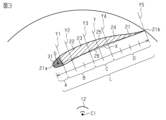
- FIG. 2 is a schematic cross-sectional view of a blade of the centrifugal fan of FIG. 1 .
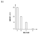
- 10 is a graph showing the magnitude of noise reduction effect versus the installation position of a pressure fluctuation suppressing portion on a blade.
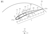
- FIG. 11 is a schematic cross-sectional view of a blade of a centrifugal fan according to a second embodiment. 10 is a graph showing the magnitude of the noise reduction effect according to the width dimension of the hollow portion.
- FIG. 11 is a schematic cross-sectional view of a blade of a centrifugal fan according to a third embodiment.
- FIG. 11 is a graph showing blowing noise versus air volume when a pressure fluctuation suppression portion is provided only on a pressure surface, only on a suction surface, or on both the pressure surface and the suction surface of a blade, and when no pressure fluctuation suppression portion is provided on the blade.
- FIG. 4 is a schematic cross-sectional view of a blade of a centrifugal fan according to a first modified example.
- FIG. 11 is a schematic cross-sectional view of a blade of a centrifugal fan according to a second modified example.
- the centrifugal fan 11 is a device for circulating air in a room.
- the centrifugal fan 11 includes, for example, a turbo fan or a sirocco fan.
- the centrifugal fan 11 will be described as a turbo fan.
- the centrifugal fan 11 is configured to rotate in a rotation direction R of the centrifugal fan 11 to blow air sucked from the air inlet 14a radially outward.
- the rotation direction R is, for example, a counterclockwise direction.
- the rotation direction R may also be a clockwise direction.
- the centrifugal fan 11 is rotated by, for example, a motor.
- a rotation shaft 12 of the centrifugal fan 11 and a rotation shaft of the motor coincide with each other.
- the rotation shaft 12 has a central rotation axis C1.
- the centrifugal fan 11 includes a first member 13 attached to the rotating shaft 12.
- the first member 13 rotates integrally with the rotating shaft 12.
- the first member 13 is, for example, a circular plate.
- a hole in which the rotating shaft 12 is provided is formed in the center of the first member 13.
- the first member 13 is made of, for example, metal or resin.
- the centrifugal fan 11 includes a second member 14 that is disposed opposite the first member 13.
- the second member 14 is, for example, a fan shroud.
- the second member 14 is circular in shape.
- An intake port 14a that draws in air is formed in the center of the second member 14.
- the second member 14 is made of, for example, metal or resin.
- the centrifugal fan 11 has blades 21 arranged between the first member 13 and the second member 14 in the axial direction of the centrifugal fan 11. Between the first member 13 and the second member 14, a plurality of blades 21 are arranged at predetermined intervals so as to surround the periphery of the rotating shaft 12.
- the number of blades 21 is 10 or less. Preferably, the number of blades 21 is 6.
- the number of blades 21 may be anywhere between 10 and 7, or between 5 and 2.
- Each of the plurality of blades 21 has the same shape.
- the blade 21 has a leading edge 21a and a trailing edge 21b.
- the leading edge 21a is located downstream in the direction of rotation R.
- the leading edge 21a is located on the rotating shaft 12 side.
- the leading edge 21a is located radially inward of the centrifugal fan 11 relative to the trailing edge 21b.
- the leading edge 21a curves toward the downstream side in the direction of rotation R.
- the middle portion of the leading edge 21a in the axial direction is curved so that it protrudes most toward the downstream side in the direction of rotation R.
- the trailing edge 21b is located upstream in the direction of rotation R.
- the trailing edge 21b is located radially outward of the centrifugal fan 11 than the leading edge 21a.
- the trailing edge 21b includes, for example, an uneven portion 21c and a notch 21d.
- the uneven portion 21c has, for example, a sawtooth shape.
- the uneven portion 21c is provided on the second member 14 side of the trailing edge 21b.
- the notch 21d is provided on the first member 13 side of the trailing edge 21b.
- the uneven portion 21c and the notch 21d may be omitted.
- the blades 21 gradually become thicker from the trailing edge 21b to the leading edge 21a.
- An outlet 21e is provided between the leading edge 21a of one blade 21 and the trailing edge 21b of the other blade 21 of two circumferentially adjacent blades 21.
- the blade 21 is formed by a solid portion 22 and a pressure fluctuation suppression portion 31.
- the solid portion 22 is dense.
- the material of the solid portion 22 is not particularly limited.
- the material of the solid portion 22 is, for example, metal or resin.
- the solid portion 22 has a higher density than the pressure fluctuation suppression portion 31. Details of the pressure fluctuation suppression portion 31 will be described later.
- FIG. 3 shows a blade cross section perpendicular to the rotation axis 12.
- the blade cross section is, for example, a cross section of the blade 21 in a direction perpendicular to the rotation axis 12.
- the blade cross section is, for example, a cross section of the blade 21 at an equal distance from the first member 13.
- the line connecting the leading edge 21a and the trailing edge 21b is defined as the imaginary line X.
- the dimension of the imaginary line X is defined as the blade chord length L.
- the wing 21 includes a leading edge portion 23 and a trailing edge portion 24.
- a center boundary line Y is defined that passes through a point located 50% of the chord length L from the leading edge 21a and is perpendicular to the chord length L.
- the leading edge portion 23 is the portion of the wing 21 closer to the leading edge 21a than the center boundary line Y.
- the trailing edge portion 24 is the portion of the wing 21 closer to the trailing edge 21b than the center boundary line Y.
- the leading edge portion 23 is wider in the direction perpendicular to the chord length L than the trailing edge portion 24.
- the blade 21 has a positive pressure surface 25 and a negative pressure surface 26.
- the positive pressure surface 25 is a blade surface where the air flow creates positive pressure in the adjacent space when the centrifugal fan 11 is rotated.
- the negative pressure surface 26 is a blade surface where the air flow creates negative pressure in the adjacent space when the centrifugal fan 11 is rotated.
- the pressure fluctuation suppressing portion 31 is configured to reduce pressure fluctuations occurring in the blade 21.
- the pressure fluctuation suppressing portion 31 is provided, for example, on the leading edge 21a. Furthermore, the pressure fluctuation suppressing portion 31 is also provided on a portion of the leading edge portion 23 other than the leading edge 21a.
- the pressure fluctuation suppressing portion 31 is formed integrally with the solid portion 22 by insert molding, bonding or fitting. In Figures 1 to 3, 5, 7, 9, and 10, the pressure fluctuation suppressing portion 31 is represented by dots.
- the pressure fluctuation suppression section 31 is provided on the positive pressure surface 25 or the negative pressure surface 26 of the blade 21.
- the pressure fluctuation suppression section 31 is provided on both the positive pressure surface 25 and the negative pressure surface 26 of the blade 21.
- the pressure fluctuation suppression section 31 is provided so as to communicate with the positive pressure surface 25 and the negative pressure surface 26 of the blade 21.
- the pressure fluctuation suppression section 31 may be provided only on the positive pressure surface 25 or only on the negative pressure surface 26 of the blade 21.
- the material of the pressure fluctuation suppression unit 31 is not particularly limited.
- the material of the pressure fluctuation suppression unit 31 is, for example, a resin, a ceramic, a metal, etc.
- the resin is a foamed resin.
- the ceramic or metal is a porous sintered body.
- the metal may be a net-like body also known as a mesh.
- the pressure fluctuation suppression section 31 is formed, for example, from a porous material.
- the porous material connects the positive pressure surface 25 and the negative pressure surface 26 of the blade 21.
- the porous material has pores that connect the positive pressure surface 25 and the negative pressure surface 26 of the blade 21.
- the positive pressure surface 25 is the surface from which air flows out of the pressure fluctuation suppression section 31 when the centrifugal fan 11 is rotated.
- the negative pressure surface 26 is the surface from which air flows in from the pressure fluctuation suppression section 31 when the centrifugal fan 11 is rotated.
- the pressure fluctuation suppression section 31 has a surface center of gravity G.
- the surface center of gravity G is the center of gravity of the cross section of the pressure fluctuation suppression section 31 when the specific gravity of the pressure fluctuation suppression section 31 is uniform.
- the position of the surface center of gravity G of the pressure fluctuation suppression section 31 is closer to the leading edge 21a than to the trailing edge 21b.
- a first boundary line Y1 is defined on the imaginary line X, passing through a point located 10% of the chord length L from the leading edge 21a and perpendicular to the imaginary line X.
- a second boundary line Y2 is defined on the imaginary line X, passing through a point located 20% of the chord length L from the leading edge 21a and perpendicular to the imaginary line X.
- a third boundary line Y3 is defined on the imaginary line X, passing through a point located 40% of the chord length L from the leading edge 21a and perpendicular to the imaginary line X.
- a fourth boundary line Y4 is defined on the imaginary line X, passing through a point located 60% of the chord length L from the leading edge 21a and perpendicular to the imaginary line X.
- a fifth boundary line Y5 is defined on the imaginary line X, passing through a point located 100% of the chord length L from the leading edge 21a and perpendicular to the imaginary line X.
- the surface center of gravity G is located within 40% of the chord length L from the leading edge 21a. Specifically, the surface center of gravity G is located in the area on the leading edge 21a side of the third boundary line Y3 in the blade cross section. Preferably, the surface center of gravity G is located within 20% of the chord length L from the leading edge 21a. Specifically, the surface center of gravity G is located in the area on the leading edge 21a side of the second boundary line Y2 in the blade cross section.
- Figure 4 shows an example of the noise reduction effect obtained depending on the region where the pressure fluctuation suppression section 31 is provided in the chord direction along the imaginary line X.
- region A is defined as from the leading edge 21a to the first boundary line Y1
- region B is defined as from the first boundary line Y1 to the third boundary line Y3
- region C is defined as from the third boundary line Y3 to the fourth boundary line Y4
- region D is defined as from the fourth boundary line Y4 to the fifth boundary line Y5.
- the noise reduction effect is greater than when the pressure fluctuation suppression unit 31 is provided in regions B to D.
- the noise reduction effect is greater than when the pressure fluctuation suppression unit 31 is provided in regions C and D.
- the noise reduction effect is greater than when the pressure fluctuation suppression unit 31 is provided in region D.
- a centrifugal fan 11 comprises a first member 13 attached to a rotating shaft 12, a second member 14 provided at a position opposite the first member 13, and a blade 21 arranged between the first member (13) and the second member (14), the blade 21 including a solid portion 22 and a pressure fluctuation suppression portion 31, the pressure fluctuation suppression portion 31 being provided on a positive pressure surface 25 or a negative pressure surface 26 of the blade 21, the blade 21 having a leading edge 21a located radially inward and a trailing edge 21b located radially outward, and the position of the surface center of gravity G of the pressure fluctuation suppression portion 31 is closer to the leading edge 21a than to the trailing edge 21b.
- the portion on the trailing edge 21b side of the blade 21 is thinner than the portion on the leading edge 21a side, so the portion on the trailing edge 21b side has lower strength and rigidity than the portion on the leading edge 21a side. Therefore, the portion on the trailing edge 21b side of the blade 21 is more likely to deform than the portion on the leading edge 21a side.
- the ratio of the amount of pressure rise to the amount of air blown is large, and the load on the blade 21 is large.
- the pressure fluctuation suppression section 31 which has lower strength and rigidity than the solid section 22, is provided on the trailing edge 21b, the adverse effects of deformation of the blade 21 are greater, making it difficult to achieve a low noise effect.
- the pressure fluctuation suppression section 31 is disposed on the portion on the leading edge 21a side of the blade 21, so noise can be reduced favorably.
- noise caused by vortex turbulence interfering with the blade 21 can be reduced more than when the surface center of gravity G is located at a position greater than 40% of the blade chord length L from the leading edge 21a.
- the surface center of gravity G is located within 20% of the chord length L from the leading edge 21a.
- noise caused by turbulence of vortexes interfering with the blade 21 can be reduced more than when the surface center of gravity G is located at a position greater than 20% of the blade chord length L from the leading edge 21a.
- the pressure fluctuation suppressing portion 31 is provided on the leading edge 21a.
- the pressure fluctuation suppression section 31 is provided on the leading edge 21a, so noise caused by vortex turbulence interfering with the blade 21 can be reduced more than if the pressure fluctuation suppression section 31 were not provided on the leading edge 21a.
- the pressure fluctuation suppression portion 31 is provided to communicate between the positive pressure surface 25 and the negative pressure surface 26 . According to this configuration, the positive pressure surface 25 and the negative pressure surface 26 are connected, so that pressure fluctuations caused by airflow turbulence can be sufficiently suppressed, thereby reducing noise caused by vortex turbulence interfering with the blade 21.
- the pressure fluctuation suppressing portion 31 is made of a porous material. With this configuration, pressure fluctuations that cause noise near the blade surface are eliminated by the airflow passing through the inside of the porous material, suppressing the development of vortices near the blade surface, thereby reducing noise caused by turbulence of vortices that interfere with the blade 21.
- Second Embodiment A centrifugal fan according to a second embodiment will be described with reference to Figures 1, 2, 5, and 6. In the second embodiment, differences from the first embodiment will be described. Members similar to those in the first embodiment will be given the same names and will not be described.
- the blade 21 further has a hollow portion 27.
- the hollow portion 27 is adjacent to the pressure fluctuation suppressing portion 31.
- the pressure fluctuation suppressing portion 31 is adjacent to the hollow portion 27 so as to surround the periphery thereof.
- the hollow portion 27 is provided in the leading edge portion 23 of the blade 21.
- the hollow portion 27 communicates with the pressure surface 25 and the suction surface 26 via the pressure fluctuation suppression portion 31.
- the hollow portion 27 may communicate only with the positive pressure surface 25 via the pressure fluctuation suppression portion 31.
- the hollow portion 27 may communicate only with the suction surface 26 via the pressure fluctuation suppression portion 31.
- the hollow portion 27 is adjacent to the solid portion 22 in the chord direction along the imaginary line X.
- the solid portion 22 includes a portion provided in the trailing edge portion 24.
- the solid portion 22 may also include a portion provided in the leading edge portion 23.
- the surface center of gravity G is located in the hollow portion 27.
- the width dimension S of the portion having the greatest width in the direction perpendicular to the blade chord length L is 12 mm or more.
- 6 shows an example of the noise reduction effect obtained depending on the width dimension S.
- the width dimension S is 12 mm or more
- the noise reduction effect is greater than when the width dimension S is less than 12 mm.
- the width dimension S is 12 mm or more
- the noise reduction effect increases as the width dimension S increases. In one example, when the width dimension S is 12 mm, the noise reduction effect is greater than when the width dimension S is 6 mm.
- the blade 21 further has a hollow portion 27 , and the hollow portion 27 is adjacent to the pressure fluctuation suppressing portion 31 .
- the airflow near the blade surface can be transmitted in the direction toward the inside of the blade, away from the blade surface, thereby suppressing pressure fluctuations caused by airflow turbulence occurring near the blade surface, thereby reducing noise caused by vortex turbulence interfering with the blade 21.
- the width dimension S of the widest part in the direction perpendicular to the chord length L is 12 mm or more.
- the airflow near the blade surface can pass in the direction toward the inside of the blade, away from the blade surface, so pressure fluctuations caused by turbulence in the airflow at the blade surface can be suppressed, thereby reducing noise caused by turbulence of vortices interfering with the blade 21.
- the width dimension S 12 mm or more the noise reduction effect can be further increased.
- centrifugal fan according to a third embodiment will be described with reference to Figures 1, 2, 7, and 8.
- differences from the first and second embodiments will be described.
- Members similar to those in the first and second embodiments will be given the same names and descriptions thereof will be omitted.
- the blade 21 has a hollow portion 27.
- the hollow portion 27 is adjacent to the pressure fluctuation suppressing portion 31.
- the hollow portion 27 is provided in the leading edge portion 23 of the blade 21.
- the pressure fluctuation suppressing portion 31 is provided only on the negative pressure surface 26.
- the pressure fluctuation suppressing portion 31 causes the hollow portion 27 to communicate only with the negative pressure surface 26.
- the solid portion 22 includes a first solid portion 22a and a second solid portion 22b.
- the first solid portion 22a is provided at the leading edge 21a.
- the second solid portion 22b is provided at the trailing edge portion 24.
- a portion of the second solid portion 22b is provided at the leading edge portion 23.
- the hollow portion 27 is adjacent to the first solid portion 22a and the second solid portion 22b. In the chord direction along the imaginary line X, the hollow portion 27 is provided between the first solid portion 22a and the second solid portion 22b.
- the blade 21 further has a lid portion 28.
- the solid portion 22 includes the lid portion 28.
- the lid portion 28 is provided between the first solid portion 22a and the second solid portion 22b in the blade chord direction along the imaginary line X.
- the lid portion 28 is provided on the pressure surface 25.
- the lid portion 28 is configured to cover a recess 29 provided in the blade 21.
- the hollow portion 27 is formed by the lid portion 28 covering the recess 29.
- a pressure fluctuation suppression section 31 may be provided between the lid section 28 and the first solid section 22a.
- the pressure fluctuation suppression section 31 is, for example, a gap between the lid section 28 and the first solid section 22a.
- a pressure fluctuation suppression section 31 may be provided between the lid section 28 and the second solid section 22b.
- the pressure fluctuation suppression section 31 is, for example, a gap between the lid section 28 and the second solid section 22b.
- the lid portion 28 may be included in the pressure fluctuation suppressing portion 31.
- the lid portion 28 is made of a porous material.
- the surface center of gravity G is located in the hollow portion 27.
- the width dimension S of the portion having the greatest width in the direction perpendicular to the blade chord length L is 12 mm or more.
- Figure 8 shows a graph of the blowing noise versus air volume for the first, second, third, and fourth patterns.
- the first pattern is when the pressure fluctuation suppression section 31 is provided only on the negative pressure surface 26.
- the second pattern is when the pressure fluctuation suppression section 31 is provided only on the positive pressure surface 25.
- the third pattern is when the pressure fluctuation suppression section 31 is provided on both the positive pressure surface 25 and the negative pressure surface 26.
- the fourth pattern is when the pressure fluctuation suppression section 31 is not provided on the blade 21.
- the blowing noise relative to the air volume is smaller than in the first, second, and fourth patterns.
- the blowing noise relative to the air volume is smaller than in the second and fourth patterns.
- the blowing noise relative to the air volume is smaller than in the fourth pattern.
- the solid portion 22 is provided on the leading edge 21a. According to this configuration, since the solid portion 22 is provided at the leading edge 21a, the strength and rigidity of the blade 21 can be increased.
- the pressure fluctuation suppressing portion 31 is provided only on the negative pressure surface 26 . According to this configuration, by providing the pressure fluctuation suppressing portion 31 only on the suction surface 26, costs can be reduced and noise caused by turbulence of vortices interfering with the blades 21 can be reduced.
- the blade 21 further has a lid portion 28 and a recess 29 , and the hollow portion 27 is formed by the lid portion 28 and the recess 29 . According to this configuration, the blade 21 is divided into the cover portion 28 and the solid portion 22, and by assembling these, the hollow portion 27 can be suitably formed.
- centrifugal fan 11 of the present disclosure may be configured in the following modified examples or a combination of at least two modified examples that are not mutually contradictory.
- the blade 21 may be formed hollow, and the pressure fluctuation suppression section 31 may be provided only on the negative pressure surface 26.
- the solid section 22 and the pressure fluctuation suppression section 31 are configured to surround the hollow section 27.
- the pressure fluctuation suppression section 31 may be provided only on the positive pressure surface 25.
- the hollow section 27 is formed by the lid section 28 covering the recess 29.
- the pressure fluctuation suppression section 31 may be provided only on the positive pressure surface 25.
- the hollow section 27 communicates only with the positive pressure surface 25 via the pressure fluctuation suppression section 31.
- centrifugal fan 11 Although an embodiment of the centrifugal fan 11 has been described above, it will be understood that various modifications of the form and details are possible without departing from the spirit and scope of the centrifugal fan 11 described in the claims.
- 11 centrifugal fan, 12... rotating shaft, 13... first member, 14... second member, 21... blade, 21a... leading edge, 21b... trailing edge, 22... solid portion, 25... positive pressure surface, 26... negative pressure surface, 27... hollow portion, 31... pressure fluctuation suppression portion, G... center of gravity of surface, L... blade chord length, S... width dimension.
Landscapes
- Engineering & Computer Science (AREA)
- Mechanical Engineering (AREA)
- General Engineering & Computer Science (AREA)
- Structures Of Non-Positive Displacement Pumps (AREA)
Abstract
Description
本開示の目的の1つは、好適に騒音を抑制できる遠心ファンを提供することである。
第3観点の遠心ファンは、第2観点の遠心ファンにおいて、前記面重心は、前記前縁から前記翼弦長の20%以内に位置する。
第4観点の遠心ファンは、第1から第3観点のいずれか1つの遠心ファンにおいて、前記中実部は、前記前縁に設けられる。
第5観点の遠心ファンは、第1から第3観点のいずれか1つの遠心ファンにおいて、前記圧力変動抑制部は、前記前縁に設けられる。
第6観点の遠心ファンは、第1から第5観点のいずれか1つの遠心ファンにおいて、前記圧力変動抑制部は、前記正圧面と、前記負圧面と、を連通するように設けられる。
第7観点の遠心ファンは、第1から第5観点のいずれか1つの遠心ファンにおいて、前記圧力変動抑制部は、前記負圧面にのみ設けられる。
第8観点の遠心ファンは、第1から第7観点のいずれか1つの遠心ファンにおいて、前記翼は、中空部をさらに有し、前記中空部は、前記圧力変動抑制部に隣接する。
この構成によれば、翼面付近において騒音の原因になる圧力変動は、翼面付近の気流が多孔質材の内部を透過することによって除去されるため、翼面付近における渦の発達が抑制される。したがって、翼に干渉する渦の乱れに起因する騒音を低減できる。
図1から図4を参照して、第1実施形態の遠心ファン11について説明する。
<遠心ファン>
遠心ファン11は、室内の空気を循環させるための装置である。遠心ファン11は、例えば、ターボファンまたはシロッコファンを含む。本実施形態では、遠心ファン11をターボファンとして説明する。遠心ファン11は、遠心ファン11の回転方向Rに回転することによって、空気の吸込口14aから吸い込んだ空気を径方向外側に吹き出すように構成される。回転方向Rは、例えば、反時計回り方向である。回転方向Rは、時計回り方向であってもよい。
遠心ファン11は、回転軸12に取り付けられる第1部材13を備える。第1部材13は、回転軸12と一体回転する。第1部材13は、例えば、円形の板である。第1部材13の中心には、回転軸12が設けられる孔が形成される。第1部材13の材質は、例えば、金属または樹脂である。
圧力変動抑制部31は、翼21に生じる圧力変動を低減するように構成される。圧力変動抑制部31は、例えば、前縁21aに設けられる。さらに、圧力変動抑制部31は、前縁部23のうちの前縁21aとは異なる部分にも設けられる。圧力変動抑制部31は、インサート成形、接着または嵌め込みによって中実部22と一体に形成される。図1から図3、図5、図7、図9、および、図10では、圧力変動抑制部31は、ドットによって表示されている。
第1実施形態の効果について説明する。
(1-1)遠心ファン11は、回転軸12に取り付けられる第1部材13と、第1部材13と対向する位置に設けられる第2部材14と、第1部材(13)と前記第2部材(14)との間に配置される翼21と、を備え、翼21は、中実部22と圧力変動抑制部31とを含み、圧力変動抑制部31は、翼21の正圧面25または負圧面26に設けられ、翼21は、径方向内側に位置する前縁21aと、径方向外側に位置する後縁21bと、を有し、圧力変動抑制部31の面重心Gの位置は、後縁21bよりも前縁21aに近い。
(1-3)面重心Gは、前縁21aから翼弦長Lの20%以内に位置する。
(1-3)圧力変動抑制部31は、前縁21aに設けられる。
この構成によれば、正圧面25と、負圧面26と、が連通することによって、気流の乱れに起因する圧力変動を十分に抑制できるため、翼21に干渉する渦の乱れに起因する騒音を低減できる。
この構成によれば、翼面付近において騒音の原因になる圧力変動は気流が多孔質材の内部を透過することによって除去されるため、翼面付近における渦の発達が抑制される。したがって、翼21に干渉する渦の乱れに起因する騒音を低減できる。
図1、図2、図5、および、図6を参照して、第2実施形態の遠心ファンについて説明する。第2実施形態では、第1実施形態と異なる点について説明する。第1実施形態と同様の部材については、同一の名称を付すことによって説明を省略する。
中空部27は、翼21の前縁部23に設けられる。中空部27は、圧力変動抑制部31によって、正圧面25と、負圧面26と、連通する。中空部27は、圧力変動抑制部31によって、正圧面25のみと連通してもよい。中空部27は、圧力変動抑制部31によって、負圧面26のみと連通してもよい。
図6には、幅寸法Sの大きさに応じて得られる、低騒音効果の一例が示される。幅寸法Sが12mm以上の場合、幅寸法Sが12mm未満の場合よりも低騒音効果が大きくなる。幅寸法Sが12mm以上の場合、幅寸法Sが大きくなるほど、低騒音効果が大きくなる。一例では、幅寸法Sが12mmの場合、幅寸法Sが6mmの場合よりも低騒音効果が大きい。
第2実施形態の効果について説明する。第2実施形態では、第1実施形態の効果に加えて以下の効果を得ることができる。
この構成によれば、翼面付近の気流を翼面から遠ざかる翼内部方向に透過できるため、翼面付近で生じる気流の乱れに起因する圧力変動を抑制することができ、よって翼21に干渉する渦の乱れに起因する騒音を低減できる。
図1、図2、図7、および、図8を参照して、第3実施形態の遠心ファンについて説明する。第3実施形態では、第1実施形態および第2実施形態と異なる点について説明する。第1実施形態および第2実施形態と同様の部材については、同一の名称を付すことによって説明を省略する。
圧力変動抑制部31は、負圧面26のみに設けられる。中空部27は、圧力変動抑制部31によって、負圧面26のみと連通する。
面重心Gは、翼断面において、中空部27にある。中空部27において、翼弦長Lに垂直な方向における幅が、最も大きい部分の幅寸法Sは、12mm以上である。
第3実施形態の効果について説明する。第3実施形態では、第1実施形態および第2実施形態の効果に加えて以下の効果を得ることができる。
この構成によれば、中実部22が前縁21aに設けられるため、翼21の強度および剛性を高くできる。
この構成によれば、負圧面26にのみ圧力変動抑制部31を設けることによって、コストが低減し、かつ、翼21に干渉する渦の乱れに起因する騒音を低減できる。
この構成によれば、翼21が蓋部28と中実部22とに分割されて、組み立てることによって、中空部27を好適に形成できる。
本開示の遠心ファン11は、上記の各実施形態以外に、例えば、以下に示される変更例および相互に矛盾しない少なくとも二つの変更例を組み合わせた形態としてもよい。
Claims (10)
- 遠心ファン(11)であって、
回転軸(12)に取り付けられる第1部材(13)と、
前記第1部材(13)と対向する位置に設けられる第2部材(14)と、
前記第1部材(13)と前記第2部材(14)との間に配置される翼(21)と、を備え、
前記翼(21)は、中実部(22)と圧力変動抑制部(31)とを含み、
前記圧力変動抑制部(31)は、前記翼(21)の正圧面(25)または負圧面(26)に設けられ、
前記翼(21)は、径方向内側に位置する前縁(21a)と、径方向外側に位置する後縁(21b)と、を有し、
前記圧力変動抑制部(31)の面重心(G)の位置は、前記後縁(21b)よりも前記前縁(21a)に近い、
遠心ファン。 - 前記回転軸(12)に垂直な翼断面において、前記前縁(21a)と、前記後縁(21b)と、を繋ぐ線の寸法を翼弦長(L)とする場合、前記面重心(G)は、前記前縁(21a)から前記翼弦長(L)の40%以内に位置する、
請求項1に記載の遠心ファン。 - 前記面重心(G)は、前記前縁(21a)から前記翼弦長(L)の20%以内に位置する、
請求項2に記載の遠心ファン。 - 前記中実部(22)は、前記前縁(21a)に設けられる、
請求項1から3のいずれか一項に記載の遠心ファン。 - 前記圧力変動抑制部(31)は、前記前縁(21a)に設けられる、
請求項1から3のいずれか一項に記載の遠心ファン。 - 前記圧力変動抑制部(31)は、前記正圧面(25)と、前記負圧面(26)と、を連通するように設けられる、
請求項1から5のいずれか一項に記載の遠心ファン。 - 前記圧力変動抑制部(31)は、前記負圧面(26)にのみ設けられる、
請求項1から5のいずれか一項に記載の遠心ファン。 - 前記翼(21)は、中空部(27)をさらに有し、
前記中空部(27)は、前記圧力変動抑制部(31)に隣接する、
請求項1から7のいずれか一項に記載の遠心ファン。 - 前記中空部(27)において、前記前縁(21a)と、前記後縁(21b)と、を繋ぐ線の寸法を翼弦長(L)とする場合、前記翼弦長(L)に垂直な方向における幅が、最も大きい部分の幅寸法(S)は、12mm以上である、
請求項8に記載の遠心ファン。 - 前記圧力変動抑制部(31)は、多孔質材によって形成される、
請求項1から9のいずれか一項に記載の遠心ファン。
Priority Applications (3)
| Application Number | Priority Date | Filing Date | Title |
|---|---|---|---|
| CN202480041732.7A CN121368683A (zh) | 2023-06-30 | 2024-06-27 | 离心风扇 |
| EP24832058.2A EP4722543A1 (en) | 2023-06-30 | 2024-06-27 | Centrifugal fan |
| US19/431,027 US20260117780A1 (en) | 2023-06-30 | 2025-12-23 | Centrifugal fan |
Applications Claiming Priority (2)
| Application Number | Priority Date | Filing Date | Title |
|---|---|---|---|
| JP2023-108410 | 2023-06-30 | ||
| JP2023108410A JP7648928B2 (ja) | 2023-06-30 | 2023-06-30 | 遠心ファン |
Related Child Applications (1)
| Application Number | Title | Priority Date | Filing Date |
|---|---|---|---|
| US19/431,027 Continuation US20260117780A1 (en) | 2023-06-30 | 2025-12-23 | Centrifugal fan |
Publications (1)
| Publication Number | Publication Date |
|---|---|
| WO2025005200A1 true WO2025005200A1 (ja) | 2025-01-02 |
Family
ID=93939193
Family Applications (1)
| Application Number | Title | Priority Date | Filing Date |
|---|---|---|---|
| PCT/JP2024/023426 Ceased WO2025005200A1 (ja) | 2023-06-30 | 2024-06-27 | 遠心ファン |
Country Status (5)
| Country | Link |
|---|---|
| US (1) | US20260117780A1 (ja) |
| EP (1) | EP4722543A1 (ja) |
| JP (1) | JP7648928B2 (ja) |
| CN (1) | CN121368683A (ja) |
| WO (1) | WO2025005200A1 (ja) |
Citations (4)
| Publication number | Priority date | Publication date | Assignee | Title |
|---|---|---|---|---|
| JP3071287B2 (ja) | 1992-01-22 | 2000-07-31 | 松下電器産業株式会社 | 送風機羽根車 |
| JP2002054594A (ja) * | 2000-08-08 | 2002-02-20 | Daikin Ind Ltd | 遠心ファン |
| JP2005240749A (ja) * | 2004-02-27 | 2005-09-08 | Mitsubishi Electric Corp | 送風機 |
| WO2012140690A1 (ja) * | 2011-04-12 | 2012-10-18 | 三菱電機株式会社 | ターボファン、および空気調和機 |
-
2023
- 2023-06-30 JP JP2023108410A patent/JP7648928B2/ja active Active
-
2024
- 2024-06-27 CN CN202480041732.7A patent/CN121368683A/zh active Pending
- 2024-06-27 EP EP24832058.2A patent/EP4722543A1/en active Pending
- 2024-06-27 WO PCT/JP2024/023426 patent/WO2025005200A1/ja not_active Ceased
-
2025
- 2025-12-23 US US19/431,027 patent/US20260117780A1/en active Pending
Patent Citations (4)
| Publication number | Priority date | Publication date | Assignee | Title |
|---|---|---|---|---|
| JP3071287B2 (ja) | 1992-01-22 | 2000-07-31 | 松下電器産業株式会社 | 送風機羽根車 |
| JP2002054594A (ja) * | 2000-08-08 | 2002-02-20 | Daikin Ind Ltd | 遠心ファン |
| JP2005240749A (ja) * | 2004-02-27 | 2005-09-08 | Mitsubishi Electric Corp | 送風機 |
| WO2012140690A1 (ja) * | 2011-04-12 | 2012-10-18 | 三菱電機株式会社 | ターボファン、および空気調和機 |
Also Published As
| Publication number | Publication date |
|---|---|
| CN121368683A (zh) | 2026-01-20 |
| US20260117780A1 (en) | 2026-04-30 |
| JP2025007183A (ja) | 2025-01-17 |
| JP7648928B2 (ja) | 2025-03-19 |
| EP4722543A1 (en) | 2026-04-08 |
Similar Documents
| Publication | Publication Date | Title |
|---|---|---|
| CN107795516B (zh) | 轴流风扇及室外机 | |
| JP3979388B2 (ja) | 送風機 | |
| JP4035237B2 (ja) | 軸流送風機 | |
| CN107850083B (zh) | 送风机和搭载有该送风机的空调装置 | |
| CN112424480B (zh) | 一种轴向通风机 | |
| CN101203680A (zh) | 轴流风扇 | |
| WO2006006668A1 (ja) | 遠心送風機および遠心送風機を備えた空気調和装置 | |
| CN117072482B (zh) | 动叶组件、轴流风机及油烟机 | |
| JP3969354B2 (ja) | 遠心ファンおよびその用途 | |
| JP5682751B2 (ja) | 多翼送風機 | |
| JP2010124534A (ja) | 電動機用斜流ファンと該斜流ファンを備えた電動機 | |
| JP2005240749A (ja) | 送風機 | |
| CN111503019A (zh) | 离心式鼓风机 | |
| CN106104005A (zh) | 鼓风装置 | |
| JP7648928B2 (ja) | 遠心ファン | |
| JP6844526B2 (ja) | 多翼遠心ファン | |
| JP5593941B2 (ja) | シロッコファン | |
| JP2002357194A (ja) | 貫流ファン | |
| JP2019127865A (ja) | 遠心ファン | |
| KR101630579B1 (ko) | 송풍기의 임펠러 | |
| JP5147784B2 (ja) | ファンおよび軸流送風機 | |
| WO2021059899A1 (ja) | 送風機 | |
| JP7409246B2 (ja) | ターボファン | |
| JP2825220B2 (ja) | 軸流フアン | |
| JPWO2019146015A1 (ja) | 遠心送風機 |
Legal Events
| Date | Code | Title | Description |
|---|---|---|---|
| 121 | Ep: the epo has been informed by wipo that ep was designated in this application |
Ref document number: 24832058 Country of ref document: EP Kind code of ref document: A1 |
|
| WWE | Wipo information: entry into national phase |
Ref document number: 2024832058 Country of ref document: EP |
|
| WWE | Wipo information: entry into national phase |
Ref document number: 202617001737 Country of ref document: IN |
|
| ENP | Entry into the national phase |
Ref document number: 2024832058 Country of ref document: EP Effective date: 20251230 |
|
| ENP | Entry into the national phase |
Ref document number: 2024832058 Country of ref document: EP Effective date: 20251230 |
|
| WWP | Wipo information: published in national office |
Ref document number: 202617001737 Country of ref document: IN |
|
| ENP | Entry into the national phase |
Ref document number: 2024832058 Country of ref document: EP Effective date: 20251230 |
|
| NENP | Non-entry into the national phase |
Ref country code: DE |
|
| ENP | Entry into the national phase |
Ref document number: 2024832058 Country of ref document: EP Effective date: 20251230 |
|
| ENP | Entry into the national phase |
Ref document number: 2024832058 Country of ref document: EP Effective date: 20251230 |
|
| WWP | Wipo information: published in national office |
Ref document number: 2024832058 Country of ref document: EP |