WO2025004947A1 - 切換弁ブロックアセンブリ及びこれに用いられる給排気ブロック - Google Patents
切換弁ブロックアセンブリ及びこれに用いられる給排気ブロック Download PDFInfo
- Publication number
- WO2025004947A1 WO2025004947A1 PCT/JP2024/022323 JP2024022323W WO2025004947A1 WO 2025004947 A1 WO2025004947 A1 WO 2025004947A1 JP 2024022323 W JP2024022323 W JP 2024022323W WO 2025004947 A1 WO2025004947 A1 WO 2025004947A1
- Authority
- WO
- WIPO (PCT)
- Prior art keywords
- exhaust
- pilot
- supply
- switching valve
- air
- Prior art date
- Legal status (The legal status is an assumption and is not a legal conclusion. Google has not performed a legal analysis and makes no representation as to the accuracy of the status listed.)
- Ceased
Links
Images










Classifications
-
- F—MECHANICAL ENGINEERING; LIGHTING; HEATING; WEAPONS; BLASTING
- F16—ENGINEERING ELEMENTS AND UNITS; GENERAL MEASURES FOR PRODUCING AND MAINTAINING EFFECTIVE FUNCTIONING OF MACHINES OR INSTALLATIONS; THERMAL INSULATION IN GENERAL
- F16K—VALVES; TAPS; COCKS; ACTUATING-FLOATS; DEVICES FOR VENTING OR AERATING
- F16K27/00—Construction of housing; Use of materials therefor
Definitions
- the present invention relates to a switching valve block assembly that is made up of multiple switching valve blocks and an air supply/exhaust block that supplies and exhausts air to and from these blocks, connected in a row in the width direction, and to the air supply/exhaust block used in the assembly.
- a switching valve block assembly consisting of multiple switching valve blocks and an air supply/exhaust block connected in a row in the width direction is disclosed, for example, in Patent Document 1.
- this switching valve block assembly multiple switching valve blocks and an air supply/exhaust block are connected in a row in the width direction with their sides abutting against each other.
- a pair of side surfaces facing each other in the width direction of the supply and exhaust block are formed with an air supply opening for supplying air to the switching valve block and an exhaust opening for introducing air exhausted from the multiple switching valve blocks.
- the centers of these air supply openings are aligned on the same axis along the width direction and have the same shape.
- the centers of these exhaust openings are aligned on the same axis along the width direction and have the same shape.
- the technical objective of the present invention is to provide a switching valve block assembly that allows different types of switching valve blocks to be mixed in one supply/exhaust block, and an supply/exhaust block used therein.
- the switching valve block assembly of the present invention is a switching valve block assembly in which a plurality of switching valve blocks having output ports and an intake and exhaust block having an intake and exhaust port are connected in a row along the width direction with their sides abutting each other, and the assembly has a first end and a second end at both ends in the width direction, and the intake and exhaust block has a body in which a first intake opening for discharging air and a first exhaust opening for exhausting air are opened on the side of the first end of a pair of side surfaces facing each other in the width direction, and a second intake opening and a second exhaust opening are opened on the side of the second end of the pair of side surfaces, and the first intake opening, the second intake opening, and the intake port are mutually connected via an intake communication passage, and the first exhaust opening, the second exhaust opening, and the exhaust port are mutually connected via an exhaust communication passage, and the centers of the first and second intake openings are aligned along the width direction.
- the first and second exhaust openings are arranged on different axes extending in the width direction, and the centers of the first and second exhaust openings are arranged on different axes extending in the width direction, and the multiple switching valve blocks have an air intake passage and an exhaust passage penetrating between both side surfaces facing each other in the width direction, and are composed of a plurality of first and second switching valve blocks selected from the first and second switching valve blocks that can selectively communicate the air intake passage and the exhaust passage with the output port, and when the first switching valve block is coupled to the side surface on the first end side of the air intake and exhaust block, the air intake passage and the exhaust passage of the first switching valve block can be connected to the first air intake opening and the first exhaust opening of the air intake and exhaust block, and when the second switching valve block is coupled to the side surface on the second end side of the air intake and exhaust block, the air intake passage and the exhaust passage of the second switching valve block can be connected to the second air intake opening and the second exhaust opening of the air intake and exhaust block.
- the first air intake opening and the first exhaust opening of the air intake and exhaust block are arranged at a first distance on the side surface of the first end, and the second air intake opening and the second exhaust opening are arranged at a second distance different from the first distance on the side surface of the second end, and the opening area of the first air intake opening is different from the opening area of the second air intake opening, and the opening area of the first exhaust opening is different from the opening area of the second exhaust opening.
- the first and second switching valve blocks are pilot-operated switching valves
- the supply/exhaust block can be selectively switched between an external mode in which pilot air introduced from the outside is supplied to the first and/or second switching valve block, and an internal mode in which a portion of the air introduced from the air supply port is supplied as pilot air to the first and/or second switching valve block
- the supply/exhaust block comprises a first switching member attached to the body in the external mode, a second switching member attached to the body in the internal mode, and a and a mounting surface for selectively mounting these switching members, and the pair of side surfaces of the body are provided with first and second pilot supply openings for supplying pilot air to the first and/or second switching valve block, and first and second pilot exhaust openings for introducing pilot air discharged from the first and/or second switching valve block
- the mounting surface is provided with an air supply communication port communicating with the air supply port, a pilot supply communication port communicating with the first and second pilot supply openings, and a pilot exhaust communication port communicating with the first and
- the first switching member has a pilot supply port which supplies pilot air and a pilot exhaust port which exhausts pilot air, and is configured, when attached to the mounting surface, to communicate between the pilot supply port and the pilot supply communication port, and between the pilot exhaust port and the pilot exhaust communication port, and to close the air supply communication port; and the second switching member, when attached to the mounting surface, is configured to communicate between the air supply communication port and the pilot supply communication port, and to close the pilot exhaust communication port, so that
- pilot air supplied from the pilot supply port is supplied to the first and/or second switching valve block, and the pilot air discharged from the switching valve block to which the pilot air is supplied is discharged from the pilot discharge port.
- pilot air from the air supply port is supplied to the first and/or second switching valve block, and the pilot air discharged from the first and/or second switching valve block to which the pilot air is supplied is discharged through the exhaust flow path of the switching valve block.
- the respective centers of the first and second pilot supply openings are disposed on different axes extending along the width direction
- the respective centers of the first and second pilot exhaust openings are disposed on different axes extending along the width direction
- the first pilot supply opening and the first pilot exhaust opening are disposed on the side surface of the first end side at a third distance
- the second pilot supply opening and the second pilot exhaust opening are disposed on the side surface of the second end side at a fourth distance different from the third distance.
- each of the first and second switching valve blocks has a switching valve pilot supply passage and a switching valve pilot exhaust passage extending between both side surfaces facing each other in the width direction, and when the first switching valve block is coupled to the side surface of the first end side of the supply and exhaust block, the switching valve pilot supply passage and the switching valve pilot exhaust passage of the first switching valve block are connected to the first pilot supply opening and the first pilot exhaust opening of the supply and exhaust block, and when the second switching valve block is coupled to the side surface of the second end side of the supply and exhaust block, the switching valve pilot supply passage and the switching valve pilot exhaust passage of the second switching valve block are connected to the second pilot supply opening and the second pilot exhaust opening of the supply and exhaust block.
- the supply and exhaust block of the present invention is used in the switching valve block assembly.
- the present invention provides a switching valve block assembly that allows different types of switching valve blocks to be mixed in one supply/exhaust block, and an supply/exhaust block used therein.
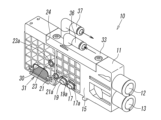
- FIG. 2 is a front perspective view of a diverter valve block assembly according to one embodiment of the present invention
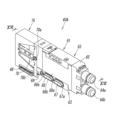
- FIG. 2 is a left side perspective view of the supply and exhaust block.
- FIG. 4 is a right side perspective view of the supply and exhaust block.
- FIG. 4 is a right side view of the supply and exhaust block.
- FIG. 4 is a left side view of the supply and exhaust block.
- FIG. 1A is a perspective view of the first switching member as viewed from above
- FIG. 1B is a perspective view of the first switching member as viewed from below.
- 8A is a bottom view of the first switching member
- FIG. 8B is a cross-sectional view of a portion corresponding to the portion viewed in the direction of arrows VIII-VIII in FIG. 8A.
- FIG. 1A is a perspective view of the second switching member as viewed from above
- FIG. 1B is a perspective view of the second switching member as viewed from below
- 10(a) is a bottom view of the second switching member
- FIG. 10(b) is a cross-sectional view of a portion corresponding to the view seen from the arrows XX in FIG. 10(a).
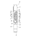
- FIG. 11 is a plan view of the air supply/exhaust block to explain the air flow within the air supply/exhaust block in the external pilot mode.
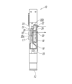
- 11 is a plan view of the air supply/exhaust block to explain the flow of air within the air supply/exhaust block in the internal pilot mode.
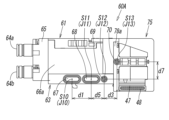
- FIG. FIG. 4 is a perspective view of a first switching valve block.
- FIG. 4 is a left side view of the first switching valve block.
- FIG. 4 is a right side view of the first switching valve block.
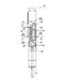
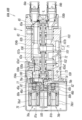
- 16 is a cross-sectional view of the first switching valve block corresponding to the XVI-XVI arrow view of FIG. 13.
- FIG. 11 is a cross-sectional view of a modified example of the first switching valve block.
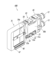
- FIG. 4 is a perspective view of a second switching valve block.
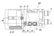
- FIG. 4 is a left side view of the second switching valve block.
- FIG. 4 is a right side view of the second switching valve block.
- FIG. 13 is a perspective view showing a modified example of a switching valve block assembly.
- FIG. 13 is a perspective view showing a modified example of the switching valve block.
- the supply and exhaust block constitutes part of the switching valve block assembly, so the supply and exhaust block will be described in the explanation of the switching valve block assembly.
- the switching valve block assembly 1 is an integrated assembly consisting of a first supply and exhaust block 10, a second supply and exhaust block 6, a plurality of pilot-type first switching valve blocks 60A, a plurality of pilot-type second switching valve blocks 60B, a first end block 90, and a second end block 95 arranged in the width direction.
- the switching valve block assembly 1 has a first end 2 and a second end 3 at both ends in the width direction, and these devices that make up the switching valve block assembly 1 are connected so that they can be attached and detached by butting their sides facing the width direction together when mounted on rails 4.
- the switching valve block assembly 1 of this embodiment is configured to supply and exhaust air to and from the first supply and exhaust block 10 via the supply and exhaust flow paths extending through the first supply and exhaust block 10 and the first switching valve blocks 60A in a lump. Furthermore, the switching valve block assembly 1 is configured to supply and exhaust air to and from the second supply and exhaust block 6 via the supply and exhaust flow paths and the pilot supply and pilot exhaust flow paths extending through the second supply and exhaust block 6 and the second switching valve blocks 60B in a lump.
- the supply and exhaust flow paths, the pilot supply and pilot exhaust flow paths will be described in detail later.
- the first and second switching valve blocks 60A, 60B are common in that they are pilot-operated switching valves formed in a block shape, but differ from each other in that they have different capacities (flow size).
- the capacity of the first switching valve block 60A is larger than that of the second switching valve block 60B.
- the first supply and exhaust block 10 can accommodate the first and second switching valve blocks 60A, 60B, which have different capacities, while the second supply and exhaust block 6 can only connect to the second switching valve block 60B.
- the first end block 90 has a connector 91 on its upper surface, which supplies power and electrical signals to the solenoids 76a1, 76b1 provided in the first and second switching valve blocks 60A, 60B.
- the second end block 95 closes the opening on the first end 2 side of the first switching valve block 60A.
- the first supply and exhaust block 10 will be described. As shown in Figures 2 to 6, the first supply and exhaust block 10 can be selectively switched between an external mode in which pilot air introduced from the outside is supplied to the first and second switching valve blocks 60A, 60B, and an internal mode in which a portion of the air introduced from the air supply port 12 is supplied as pilot air to the first and second switching valve blocks 60A, 60B.
- the first supply and exhaust block 10 has a first body 11 that is the body of the first supply and exhaust block 10, a first switching member 33 that is attached to the first body 11 in the external mode, and a second switching member 42 that is attached to the first body 11 in the internal mode.
- the first body 11 is formed in a rectangular parallelepiped shape extending in the front-rear direction.
- An air supply port 12 and an exhaust port 13 are provided at the front end of the first body 11 with a gap between them in the top and bottom.
- a pair of side surfaces 14, 15 facing each other in the width direction are each provided with first and second air supply openings 16, 17 for discharging air, first and second exhaust openings 18, 19 for discharging air, first and second pilot supply openings 20, 21 for supplying pilot air, and first and second pilot exhaust openings 22, 23 for discharging pilot air.
- a recess 24 is formed in the upper part of the first body 11, and the flat mounting surface 25 described above is formed at the bottom of this recess 24. Therefore, the external mode is selected by attaching the first switching member 33 to the mounting surface 25, and the internal mode is selected by attaching the second switching member 42 to the mounting surface 25.
- the first air supply opening 16 and the first exhaust opening 18 opened on the side surface 14 on the first end 2 side are opened at the bottom of the front side of the side surface 14.
- the first air supply opening 16 is arranged at a distance d1 horizontally forward of the first exhaust opening 18 (see FIG. 4).
- the second air supply opening 17 and the second exhaust opening 19 opened on the side surface 15 on the second end 3 side are opened at the bottom of the center of the front-rear direction of the side surface 15.
- the second air supply opening 17 is arranged at a distance d2 (d1>d2) horizontally forward of the second exhaust opening 19 (see FIG. 5).
- the first air supply opening 16 and the first exhaust opening 18 are formed as elongated holes extending in the front-rear direction and opening to the same size, and the second air supply opening 17 and the second exhaust opening 19 are also formed as elongated holes extending in the front-rear direction and opening to the same size.
- the opening area of the first air supply opening 16 is larger than the opening area of the second air supply opening 17, and the opening area of the first exhaust opening 18 is larger than the opening area of the second exhaust opening 19.
- these axes J1-J4 extend parallel to the width direction without intersecting each other.
- the first air supply opening 16 and the first exhaust opening 18 have different opening areas relative to the second air supply opening 17 and the second exhaust opening 19, and are disposed at different positions in the front-rear direction.
- the first air supply opening 16 and the first exhaust opening 18 open in a concave shape relative to the side surface 14 on the first end 2 side, and the second air supply opening 17 and the second exhaust opening 19 open at the tips of cylindrical protrusions 17a, 19a protruding from the side surface 15 on the second end 3 side.
- the first pilot supply opening 20 and the first pilot exhaust opening 22 are formed in a circular shape with an opening of the same size.
- the second pilot supply opening 21 and the second pilot exhaust opening 23 are also formed in a circular shape with an opening of the same size.
- the centers S5 and S7 of the first and second pilot supply openings 20 and 21 are disposed on different axes J5 and J7 that extend along the width direction.
- the centers S6 and S8 of the first and second pilot exhaust openings 22 and 23 are also disposed on different axes J6 and J8 that extend along the width direction. In this embodiment, these axes J5-J8 extend parallel to each other in the width direction.
- first pilot supply opening 20 and the first pilot exhaust opening 22 are arranged at different positions in the vertical and front-to-rear directions relative to the second pilot supply opening 21 and the second pilot exhaust opening 23.
- these openings 20, 22 opened on the side surface 14 on the first widthwise end 2 side are concavely opened into the side surface 14, and the openings 21, 23 opened on the side surface 15 on the second widthwise end 3 side are opened at the tips of cylindrical protrusions 21a, 23a protruding from the side surface 15.
- the recess 24 formed on the top of the first body 11 extends in the front-rear direction at the front-rear middle of the top surface of the first body 11 and is open on both sides in the width direction.
- the mounting surface 25 formed on the bottom surface of the recess 24 is formed to extend in a rectangular shape in a plan view. As shown in FIG. 6, this mounting surface 25 is provided with an intake communication port 25a communicating with the intake port 12, an exhaust communication port 25b communicating with the first and second exhaust openings 18, 19, a pilot supply communication port 25c communicating with the first and second pilot supply openings 20, 21, and a pilot exhaust communication port 25d communicating with the first and second pilot exhaust openings 22, 23.
- the air supply communication port 25a is connected to the first air supply opening 16, the second air supply opening 17, and the air supply port 12 through the air supply communication passage 26.
- one end of the air supply communication passage 26 is connected to the first and second air supply openings 16, 17, and the other end is connected to the air supply communication port 25a and the air supply port 12.
- the exhaust communication port 25b communicates with the first exhaust opening 18, the second exhaust opening 19, and the exhaust port 13 through the exhaust communication passage 27.
- one end of the exhaust communication passage 27 communicates with the first and second exhaust openings 18, 19, and the other end communicates with the exhaust communication port 25b and the exhaust port 13.
- the pilot supply communication port 25c is connected to the first and second pilot supply openings 20, 21 through the pilot supply flow passage 28.
- one end of the pilot supply flow passage 28 is connected to the first and second pilot supply openings 20, 21, and the other end is connected to the pilot supply communication port 25c.
- the pilot exhaust communication port 25d is connected to the first and second pilot exhaust openings 22, 23 through the pilot exhaust flow path 29.
- one end of the pilot exhaust flow path 29 is connected to the first and second pilot exhaust openings 22, 23, and the other end is connected to the pilot exhaust communication port 25d.
- the first switching member 33 or the second switching member 42 is selectively attached to the mounting surface 25 on which these communication ports 25a-25d are formed.
- the first switching member 33 is formed in a rectangular parallelepiped shape, and has a pilot supply port 34 for introducing pilot air and a pilot discharge port 35 for discharging pilot air discharged from the first switching valve block 60A on its upper surface.
- a pilot supply port 36 is inserted into the pilot supply port 34
- a pilot discharge port 37 is inserted into the pilot discharge port 35.
- the pilot supply port 34 is formed on the rear side of the second widthwise end 3 side of the first switching member 33, and the pilot discharge port 35 is formed on the rear side of the pilot supply port 34 and on the first widthwise end 2 side.
- a first supply groove 38 is formed inside the back side of the first switching member 33.
- the upper end of this first supply groove 38 communicates with the pilot supply port 34 and extends downward, and the lower end opens to the back side of the first switching member 33.
- the opening 38a at the lower end of the first supply groove 38 extends in the front-to-rear direction and is formed in a rectangular shape that is approximately the same size as the pilot supply communication port 25c.
- an air supply blocking portion 40 and an exhaust blocking portion 41 are formed on the back surface of the first switching member 33, which block the first air supply opening 16 and the first exhaust opening 18 formed on the mounting surface 25. These blocking portions 40, 41 close the communication openings 25a, 25b by surrounding the openings 16, 18.
- the first switching member 33 is detachably attached to the mounting surface 25 by fastening members (screws) inserted on both sides in the front-rear direction.
- pilot air When pilot air is introduced into the pilot supply port 36 with the first switching member 33 attached to the mounting surface 25 of the first supply and exhaust block 10, as shown in Figs. 2 and 11, the pilot air is discharged from the first and second pilot supply openings 20 and 21 through the first supply groove 38, the pilot supply communication port 25c, and the pilot supply passage 28.
- pilot air When pilot air is introduced into the first pilot exhaust opening 22, the pilot air is exhausted from the pilot exhaust port 37 through the pilot exhaust passage 29, the pilot exhaust communication port 25d, and the first exhaust groove 39.
- the second switching valve block 60B is coupled to the side surface 15 on the second end 3 side of the first supply and exhaust block 10, and air is supplied to the second switching valve block 60B from the second supply and exhaust block 6. Therefore, in the first supply and exhaust block 10, air is discharged only from the first pilot supply opening 20.
- the second switching member 42 has an air supply blocking section 40 and an exhaust blocking section 41 formed on its back surface, similar to the first switching member 33, and further has a pilot exhaust blocking section (blocking section) 44 that blocks the pilot exhaust communication port 25d. These blocking sections 40, 41, 44 close the communication ports 25a, 25b, 25d by surrounding the communication ports 25a, 25b, 25d.
- the second switching member 42 is detachably attached to the mounting surface 25 of the first supply and exhaust block 10 by fastening members (screws) inserted on both sides in the front-rear direction.
- the air When air is introduced into the air supply port 12 with the second switching member 42 attached to the mounting surface 25, as shown in Figures 3 and 12, the air is discharged mainly from the first air supply opening 16 through the air supply communication passage 26. A part of the air is discharged mainly from the first pilot supply opening 20 as pilot air through the air supply communication passage 26, the second groove portion 43, and the pilot supply passage 28. That is, since the second switching valve block 60B, to which air is supplied from the second air supply and exhaust block 6, is connected to the side surface 15 on the second end 3 side of the first air supply and exhaust block 10, the air is discharged mainly from the first air supply opening 16 and the first pilot supply opening 20.
- a mounting hole 30 is provided at the lower part rearward of the first and second pilot supply openings 20, 21 opened in the first body 11, penetrating in the width direction.
- a connection board 31 for receiving an electrical signal transmitted from the first end block 90 is attached inside this mounting hole 30.
- the connection board 31 is electrically connected to the connection board 48 provided on the first and second switching valve blocks 60A, 60B when these blocks are respectively coupled to the side surfaces 14, 15 of the first supply and exhaust block 10.
- the first switching valve block 60A comprises a main valve section 61 incorporating valve bodies 62a, 62b, and a pilot valve section 75 having first and second pilot solenoid valves 76a, 76b.
- the main valve section 61 has a main valve body 63 which is a body thereof, and this main valve body 63 is formed in a rectangular parallelepiped shape extending in the front-rear direction.
- a port block 65 having first and second output ports 64a, 64b is attached to the front end of the main valve body 63.
- the pilot valve section 75 has a pilot body 77 which is a body thereof, and the pilot body 77 is connected to the rear end of the main valve body 63.
- a pair of side surfaces 66a, 66b, 78a, 78b facing each other in the width direction of the main valve body 63 and the pilot body 77 are provided with a first switching valve intake opening 67 through which air is supplied, a first switching valve exhaust opening 68 through which air is exhausted, a first switching valve pilot supply opening 69 through which pilot air is supplied, and a first switching valve pilot exhaust opening 70 through which pilot air is exhausted.
- These openings 67-70 can be connected to the first intake opening 16, first exhaust opening 18, first pilot supply opening 20, and first pilot exhaust opening 22 that are opened on the first end 2 side in the width direction of the first supply and exhaust block 10 described above.
- the first switching valve air intake opening 67 and the first switching valve exhaust opening 68 which are provided on the side surface 66b on the second widthwise end 3 side of the first switching valve block 60A, open to the front lower portion of the side surface 66b. Furthermore, these openings 67, 68 extend in the front-rear direction, are open to the same size, and are formed to be substantially the same shape as the first air intake opening 16 and the first exhaust opening 18 shown in FIG. 3. Furthermore, in the front-rear direction, the first switching valve air intake opening 67 is positioned horizontally forward at a distance d1 from the first switching valve exhaust opening 68.
- the first switching valve pilot supply opening 69 opened on the side surface 66b is disposed horizontally rearward of the first switching valve exhaust opening 68 at a distance d5.
- the first switching valve pilot exhaust opening 70 is disposed at a distance d7 above the first switching valve pilot supply opening 69 and at a distance d3 rearward.
- the first switching valve pilot supply opening 69 and the first switching valve pilot exhaust opening 70 are formed in substantially the same circular shape as the first pilot supply opening 20 and the first pilot exhaust opening 22 shown in FIG. 3. In this embodiment, these openings 67-70 open at the tips of cylindrical protrusions 67a-70a (see FIG. 13) protruding from the side surface 66b on the second end 3 side.
- the first switching valve air supply opening 67, the first switching valve exhaust opening 68, the first switching valve pilot supply opening 69, and the first switching valve pilot exhaust opening 70 which are opened on the side surface 66a on the first widthwise end 2 side of the first switching valve block 60A, are opened on the side surface 66b on the second widthwise end side and are formed in the same manner as the openings 67-70.
- these openings 67-70 are concavely opened on the side surface 66a.
- the centers S10 of the first switching valve air supply openings 67 opened on each of the side surfaces 66a and 66b on both sides of the first switching valve block 60A in the width direction are arranged on the same axis J10 extending along the width direction.
- the centers S11 of the first switching valve exhaust openings 68 opened on each of the side surfaces 66a and 66b are arranged on the same axis J11 extending along the width direction.
- the centers S12 of the first switching valve pilot supply openings 69 opened on each of the side surfaces 66a and 66b are arranged on the same axis J12 extending along the width direction.
- the centers S13 of the first switching valve pilot exhaust openings 70 opened on each of the side surfaces 66a and 66b are arranged on the same axis J13 extending along the width direction.
- the first switching valve air intake openings 67, 67 are connected to each other through a switching valve air intake communication passage 71 formed in the main valve body 63.
- the first switching valve exhaust openings 68, 68 are connected to each other through a switching valve exhaust communication passage 72 formed in the main valve body 63.
- the first switching valve pilot supply openings 69, 69 are connected to each other through a switching valve pilot supply passage 73 formed in the main valve body 63.
- the first switching valve pilot exhaust openings 70, 70 are connected to each other through a switching valve pilot exhaust passage 74 formed in the main valve body 63.
- the first air supply opening 16, first exhaust opening 18, first pilot supply opening 20, and first pilot exhaust opening 22 opened on the side surface 14 of the first supply and exhaust block 10 shown in FIG. 4 can be connected to the first switching valve air supply opening 67, first switching valve exhaust opening 68, first switching valve pilot supply opening 69, and first switching valve pilot exhaust opening 70.
- the first switching valve air supply opening 67, the first switching valve exhaust opening 68, the first switching valve pilot supply opening 69, and the first switching valve pilot exhaust opening 70 which are opened on both side surfaces 66a, 66b of the first switching valve block 60A in the width direction, are the same in shape and arrangement on the side surfaces 66a, 66b. Therefore, when multiple first switching valve blocks 60A are abutted in a row in the width direction, they can be joined together with each of these openings 67-70 in communication.
- the main valve section 61 of the first switching valve block 60A is a three-port valve, and includes a main valve body 63, a piston box 100 attached to the rear end face of the main valve body 63, and a port block 65 attached to the front end face of the main valve body 63.
- the main valve body 63 is formed with a switching valve air supply communication passage 71 and a switching valve exhaust communication passage 72 that run through it in the width direction so that multiple first switching valve blocks 60A can be connected together in the width direction for use.
- a valve hole 106 is formed between both front and rear end faces of the main valve body 63, penetrating along the axis L extending in the front and rear direction.
- This valve hole 106 is formed with a switching valve air intake passage 101 located in the center in the direction of the axis L, first and second output passages 107a, 107b located on either side of it, and first and second exhaust passages 102, 103 located on either side of them and communicating with the switching valve exhaust communication passage 72.
- Valve bodies 62a, 62b are inserted on both sides of the valve hole 106 in the forward and backward directions so as to be freely slidable along the axis L. These valve bodies 62a, 62b are configured so that the acting force of the air pressure from the switching valve air supply passage 101 serves as a return force.
- first and second pistons 108a, 108b are disposed on both sides of the valve hole 106 in the axial L direction, which press the valve bodies 62a, 62b under the action of pilot air pressure.
- the first and second output flow paths 107a, 107b are located above and below the valve hole 106.
- the rear ends of the first and second output flow paths 107a, 107b open to the valve hole 106, and the front ends extend forward in the direction of the axis L and communicate with the first and second output ports 64a, 64b.
- the piston box 100 is formed with a first piston chamber 100a that opens toward the front, and a first piston 108a with a larger diameter than the valve body 62a is inserted into this first piston chamber 100a so that it can slide in the direction of the axis L.
- a second piston chamber 65a that opens toward the rear is formed in the port block 65, and a second piston 108b with a larger diameter than the valve body 62b is inserted into this second piston chamber 65a so that it can slide in the direction of the axis L.
- the main valve body 63 is formed with a first pilot supply communication passage 104a capable of supplying pilot air to the first piston chamber 100a, and a second pilot supply communication passage 104b capable of supplying pilot air to the second piston chamber 65a.
- pilot air When pilot air is supplied to the first piston chamber 100a, the force of the pilot air pressure acting on the first piston 108a, which has a larger diameter than the valve body 62a, exceeds the force of the air from the switching valve air supply passage 101 acting on the front end face of the valve body 62a, so that the valve body 62a moves forward in the direction of the axis L.
- the switching valve air supply passage 101 communicates with the first output passage 107a, and air is output from the first output port 64a.
- pilot air when pilot air is discharged from the first piston chamber 100a, the pilot air pressure acting on the first piston 108a decreases, and the force of the air acting on the front end surface of the valve body 62a is greater, so that the valve body 62a returns to the rear side in the direction of the axis L. Then, when the first pilot supply communication passage 104a communicates with the pilot exhaust passage 105, the pilot air is discharged from the switching valve pilot exhaust passage 74 or the switching valve exhaust communication passage 72. Details of the discharge of pilot air will be described later.
- the second piston 108b moves rearward, similar to when pilot air is supplied to the first piston chamber 100a, and the switching valve air supply passage 101 and the second output passage 107b communicate with each other, and air is output from the second output port 64b.
- the valve body 62b returns to the front side in the direction of the axis L.
- the second pilot supply communication passage 104b communicates with the pilot exhaust passage 105, the pilot air is discharged from the switching valve pilot exhaust passage 74 or the switching valve exhaust communication passage 72. Details of the discharge of pilot air will be described later.
- the pilot valve section 75 is provided with first and second pilot solenoid valves 76a, 76b that drive the valve bodies 62a, 62b.
- These first and second pilot solenoid valves 76a, 76b each have a first and second pilot inlet flow path 79a, 79b, a first and second pilot output flow path 80a, 80b, and a first and second pilot exhaust flow path 81a, 81b.
- first and second pilot solenoid valves 76a, 76b are configured as three-port solenoid valves that selectively switch and communicate the first and second pilot output flow paths 80a, 80b with the first and second pilot inlet flow paths 79a, 79b and the first and second pilot exhaust flow paths 81a, 81b by energizing and deenergizing the solenoids 76a1, 76b1.
- the first and second pilot inlet passages 79a, 79b are connected to the switching valve pilot supply passage 73 through a pilot input passage 109 formed across the pilot body 77 and the main valve body 63.
- the first pilot output passage 80a is connected to the first piston chamber 100a through a first pilot supply communication passage 104a formed across the pilot body 77 and the piston box 100.
- the second pilot output passage 80b is connected to the second piston chamber 65a through a second pilot supply communication passage 104b formed across the pilot body 77, the piston box 100, and the main valve body 63.
- the first and second pilot exhaust passages 81a, 81b are connected to each other through a pilot exhaust passage 105 formed across the pilot body 77 and the piston box 100.
- the pilot exhaust passage 105 is connected to the switching valve pilot exhaust passage 74 on its upstream side.
- the switching valve pilot exhaust passage 74 will be described in detail later.
- the first switching valve block 60A in this embodiment is a switching valve in the internal mode shown in FIG. 16.
- the first switching valve block 60A in this embodiment is configured so that a portion of the air supplied from the air supply port 12 of the first supply and exhaust block 10 is supplied as pilot air, and the pilot air exhausted from the first switching valve block 60A is exhausted to the switching valve exhaust communication passage 72.
- the pilot exhaust passage 105 extends across the pilot body 77 and the piston box 100, and also extends to the first exhaust passage 102 through the gap formed between the seal member 62a2 and the valve hole 106.
- the seal member 62a2 is a lip-type seal member that opens toward the front, and allows air to flow from the first piston 108a side to the first exhaust passage 102 side, while preventing air from flowing from the first exhaust passage 102 side to the first piston 108a side.
- the first and second pilot solenoid valves 76a and 76b each have a pilot valve body 82 on the front side.
- the pilot valve body 82 includes inlet valve bodies 45a and 45b and exhaust valve bodies 46a and 46b arranged in the front-rear direction and linked to each other.
- the solenoid 76a1 or the solenoid 76b1 is excited, the inlet valve body 45a or the inlet body 45b is opened to individually connect the first pilot inlet flow path 79a and the first pilot output flow path 80a, or the second pilot inlet flow path 79b and the second pilot output flow path 80b.
- a mounting hole 47 is provided at the rear bottom of the main valve body 63 of the first switching valve block 60A, penetrating in the width direction, and a connection board 48 for receiving an electrical signal transmitted from the first end block 90 is attached within this mounting hole 47.
- the connection board 48 is electrically connected to the solenoids 76a1, 76b1 of the first and second pilot solenoid valves 76a, 76b.
- the first switching valve block 60A described above is an internal mode switching valve, but the first supply and exhaust block 10 of this embodiment can also be used as an external mode switching valve.
- the first supply and exhaust block 10 in the external mode is configured to receive a portion of the air introduced from the pilot supply port 36 as pilot air, and to exhaust this supplied pilot air from the switching valve pilot exhaust flow path 74.
- the pilot exhaust flow path 105 in the first switching valve block 60A of the internal mode type described above is connected to the switching valve pilot exhaust flow path 74 in the middle, and the lip-type seal member 62a2 allows air to flow to the first exhaust flow path 102 side. For this reason, it is difficult to exhaust air from the switching valve pilot exhaust flow path 74.
- an O-ring 62a3 is attached to the land portion 62a1 of the valve body 62a in place of the lip-type seal member 62a2.
- the O-ring 62a3 can block the flow of air at the contact portion between the O-ring 62a3 and the valve hole 106.
- the pilot air discharged from the first and second pilot solenoid valves 76a, 76b can be discharged from the switching valve pilot exhaust flow path 74.
- the second switching valve block 60B will be described with reference to Figures 18-20.
- the second switching valve block 60B is configured in the same manner as the first switching valve block 60A described above. For this reason, the second switching valve block 60B will be described in terms of the differences from the first switching valve block 60A, and parts that are the same as those in the first switching valve block 60A will be given the same reference numerals and will not be described again.
- the second switching valve block 60B is formed smaller than the first switching valve block 60A.
- the second switching valve supply opening 51, the second switching valve exhaust opening 52, the second switching valve pilot supply opening 53, and the second switching valve pilot exhaust opening 54 are opened on the side surface 66a on the first end 2 side in the width direction of the second switching valve block 60B, which can be connected to the second air supply opening 17, the second exhaust opening 19, the second pilot supply opening 21, and the second pilot exhaust opening 23 opened on the side surface 15 on the second end 3 side in the width direction of the first supply and exhaust block 10.
- these openings 51-54 are opened in a concave shape on the side surface 66a.
- the side surface 66b on the second end 3 side of the second switching valve block 60B is provided with the same openings as the second switching valve air supply opening 51, the second switching valve exhaust opening 52, the second switching valve pilot supply opening 53, and the second switching valve pilot exhaust opening 54, which are provided on the side surface 66a on the first end 2 side of the second switching valve block 60B in the width direction.
- these openings 51-54 open at the tips of the protrusions 51a-54a protruding from the side surface 66b of the second switching valve block 60B.
- Air introduced from the air supply port 12 of the second supply/exhaust block 6 is supplied from the second supply/exhaust block 6 to the multiple second switching valve blocks 60B, and some of the air is supplied to the pilot valve portions 75 of the multiple second switching valve blocks 60B.
- the air discharged from the multiple second switching valve blocks 60B is returned to the second supply/exhaust block 6 and discharged from the exhaust port 13.
- the pilot air discharged from the pilot valve portions 75 of the multiple second switching valve blocks 60B is discharged from the exhaust port 13 of the second supply/exhaust block 6.
- the first supply and exhaust openings 16 and 18 formed on the side surface 14 on the first end 2 side in the width direction have different sizes and are arranged in different positions from the second supply and exhaust openings 17 and 19 opened on the side surface 15 on the second end 3 side, so that different first and second switching valve blocks 60A, 60B can be mounted together on the first supply and exhaust block 10.
- the operation of the switching valve block assembly 1 will be described with reference to Figures 1-3, 12, 16, and 17.
- the internal mode of the switching valve block assembly 1 will be described.
- air supplied to the air supply port 12 of the supply and exhaust blocks 6 and 10 is supplied from the first air supply opening 16 to the first and second pilot solenoid valves 76a and 76b of the switching valve blocks 60A and 60B, and is selectively output from the first and second output ports 64a and 64b depending on the excitation state of the pilot solenoid valves 76a and 76b.
- air returned from an external device connected to the output ports 64a and 64b is exhausted from the exhaust port 13 of the supply and exhaust blocks 6 and 10 through the switching valve exhaust communication passage 72 depending on the excitation state of the pilot solenoid valves 76a and 76b.
- a portion of the air supplied to the air supply port 12 is supplied from the first pilot supply opening 20 to the pilot solenoid valves 76a, 76b of the switching valve blocks 60A, 60B. Then, depending on the excitation state of the pilot solenoid valves 76a, 76b, the air supplied to the pilot solenoid valves 76a, 76b drives the first and second pistons 108a, 108b, and is exhausted from the exhaust port 13 of the air supply and exhaust blocks 6, 10 through the pilot exhaust flow path 105.
- the path through which the air supplied to the air supply port 12 of the air supply/exhaust block 6, 10 is output from the first and second output ports 64a, 64b of the switching valve block 60A, 60B, and the path through which the air flowing in from these output ports 64a, 64b is exhausted from the exhaust port 13 of the air supply/exhaust block 6, 10 are the same as in the internal mode described above.
- Pilot air is introduced from the pilot supply port 36 of the supply and exhaust blocks 6 and 10, and is supplied from the first pilot supply opening 20 to the pilot solenoid valves 76a and 76b of the switching valve blocks 60A and 60B.
- the pilot air supplied to the pilot solenoid valves 76a and 76b drives the first and second pistons 108a and 108b, and is exhausted from the pilot exhaust port 37 of the supply and exhaust blocks 6 and 10 through the switching valve pilot exhaust flow path 74.
- a switching valve block assembly 1 is shown in which the first and second switching valve blocks 60A, 60B are connected to the side surfaces 14, 15 of the first supply and exhaust block 10, but this is not limited to this.
- a switching valve block assembly 1' may be one in which a plurality of first switching valve blocks 60A, the first supply and exhaust block 10, and a second end block 95 are connected in sequence to the side surface 14 of the first supply and exhaust block 10, and the first end block 90 is connected to the side surface 15 of the first supply and exhaust block 10.
- the first supply and exhaust block 10 can be used exclusively as the first switching valve block 60A, further widening the range of options for usability of the first supply and exhaust block 10.
- first and second switching valve blocks 60A, 60B in the above-mentioned embodiment are dual-type switching valve blocks having valve bodies 62a, 62b, but as shown in FIG. 22, these first and second switching valve blocks 60A, 60B may be single-type switching valve blocks having one valve body 85.
- the first and second switching valve blocks 60A', 60B' having this one valve body 85 have substantially the same structure as the first and second switching valve blocks 60A, 60B described above. For this reason, the first and second switching valve blocks 60A', 60B' will be assigned the same reference numerals to the same parts as the first and second switching valve blocks 60A, 60B, and their explanation will be omitted, and only the differences will be explained.
- one valve body 85 is inserted in a valve hole 84 provided in the main valve body 63 so as to be slidable in the axial direction L.
- pilot air is supplied to the first piston chamber 100a and pilot air is exhausted from the second piston chamber 65a
- the valve body 85 moves forward in the axial direction L.
- pilot air is exhausted from the first piston chamber 100a and pilot air is supplied to the second piston chamber 65a
- the valve body 85 moves rearward in the axial direction L.
- an O-ring 62a3 is attached to the land portion 62a1 on the rear end side of the valve body 85, and in the internal mode, a lip-type seal member 62a2 with an opening on the front side is attached.
Landscapes
- Engineering & Computer Science (AREA)
- General Engineering & Computer Science (AREA)
- Mechanical Engineering (AREA)
- Multiple-Way Valves (AREA)
- Valve Housings (AREA)
Abstract
Description
2 第1端
3 第2端
10 第1給排気ブロック(給排気ブロック)
11 第1ボディ(ボディ)
12 給気ポート
13 排気ポート
14、15、66a、66b 側面
16 第1給気用開口
17 第2給気用開口
18 第1排気用開口
19 第2排気用開口
20 第1パイロット供給用開口
21 第2パイロット供給用開口
22 第1パイロット排気用開口
23 第2パイロット排気用開口
25 取付面
25a 給気用連通口
25c パイロット供給用連通口
25d パイロット排気用連通口
26 給気用連通流路(給気流路)
27 排気用連通流路(排気流路)
28 パイロット供給流路
29 パイロット排気流路
33 第1切換部材
34 パイロット供給口
35 パイロット排出口
42 第2切換部材
60A 第1切換弁ブロック(切換弁ブロック)
60B 第2切換弁ブロック(切換弁ブロック)
64a 第1出力ポート(出力ポート)
64b 第2出力ポート(出力ポート)
71 切換弁給気連通流路(給気流路)
72 切換弁排気連通流路(排気流路)
73 切換弁パイロット供給流路
74 切換弁パイロット排気流路
S1、S2、S3、S4、S5、S6、S7、S8、S10、S11、S12、S13 中心
J1、J2、J3、J4、J5、J6、J7、J8、J10、J11、J12、J13 軸線
Claims (6)
- 出力ポートを有する複数の切換弁ブロックと、給気ポート及び排気ポートを有する給排気ブロックとが、相互に側面を当接させた状態で幅方向に沿って一列に連結され、前記幅方向の両端に第1端及び第2端を有する切換弁ブロックアセンブリであって、
前記給排気ブロックは、前記幅方向に互いに背向する一対の側面のうちの前記第1端側の側面にエアを吐出するための第1給気用開口、及びエアを排気するための第1排気用開口が開設され、前記一対の側面のうちの前記第2端側の側面に第2給気用開口及び第2排気用開口が開設されたボディを有し、
前記第1給気用開口、前記第2給気用開口及び前記給気ポートは、給気用連通流路を介して相互に連通し、
前記第1排気用開口、前記第2排気用開口及び前記排気ポートは、排気用連通流路を介して相互に連通しており、
前記第1及び第2給気用開口のそれぞれの中心が、前記幅方向に沿って延びる互いに異なる軸線上に配置され、
前記第1及び第2排気用開口のそれぞれの中心が、前記幅方向に沿って延びる互いに異なる軸線上に配置されており、
前記複数の切換弁ブロックは、前記幅方向に互いに背向する両側面間に貫設された給気流路及び排気流路を有し、前記出力ポートに対して前記給気流路及び前記排気流路を選択的に連通可能な第1及び第2切換弁ブロックの中から選択された複数のものから構成され、
前記第1切換弁ブロックを前記給排気ブロックの前記第1端側の側面に結合させた際に、前記第1切換弁ブロックの前記給気流路及び前記排気流路が、前記給排気ブロックの前記第1給気用開口及び前記第1排気用開口に連結可能であり、
前記第2切換弁ブロックを前記給排気ブロックの前記第2端側の側面に結合させた際に、前記第2切換弁ブロックの前記給気流路及び前記排気流路が、前記給排気ブロックの前記第2給気用開口及び前記第2排気用開口に連結可能である、
ことを特徴とする切換弁ブロックアセンブリ。 - 前記給排気ブロックの前記第1給気用開口及び前記第1排気用開口は、前記第1端側の側面において第1距離を有して配され、
前記第2給気用開口及び前記第2排気用開口は、前記第2端側の側面において第1距離とは異なる第2距離を有して配されており、
前記第1給気用開口の開口面積は、前記第2給気用開口の開口面積と異なり、
前記第1排気用開口の開口面積は、前記第2排気用開口の開口面積と異なる、
ことを特徴とする請求項1に記載の切換弁ブロックアセンブリ。 - 前記第1及び第2切換弁ブロックは、パイロット式切換弁であり、
前記給排気ブロックは、外部から導入されるパイロットエアを前記第1及び又は第2切換弁ブロックに供給する外部モード、又は、前記給気ポートから導入されるエアの一部をパイロットエアとして前記第1及び又は第2切換弁ブロックに供給する内部モードに、選択的に切換可能であり、
前記給排気ブロックは、外部モードにおいて前記ボディに装着される第1切換部材と、内部モードにおいて前記ボディに装着される第2切換部材と、前記ボディに形成されこれら切換部材を選択的に装着する取付面と、を有し、
前記ボディの前記一対の側面には、前記第1及び又は第2切換弁ブロックにパイロットエアを供給する第1及び第2パイロット供給用開口と、前記第1及び又は第2切換弁ブロックから排出されるパイロットエアを導入する第1及び第2パイロット排気用開口と、が開設され、
前記取付面には、前記給気ポートに連通する給気用連通口と、前記第1及び第2パイロット供給用開口に連通するパイロット供給用連通口と、前記第1及び第2パイロット排気用開口に連通するパイロット排気用連通口と、が開設され、
前記第1切換部材は、パイロットエアを供給するパイロット供給口と、パイロットエアを排出するパイロット排出口とを有し、前記取付面に装着された際に、前記パイロット供給口と前記パイロット供給用連通口とを連通し、且つ前記パイロット排出口と前記パイロット排気用連通口とを連通し、さらに前記給気用連通口を閉塞するように構成され、
前記第2切換部材は、前記取付面に装着された際に、前記給気用連通口と前記パイロット供給用連通口とを連通し、さらに前記パイロット排気用連通口を閉塞するように構成され、
それにより、外部モードにおいては、前記パイロット供給口から供給されるパイロットエアが前記第1及び又は第2切換弁ブロックに供給され、そのパイロットエアが供給された切換弁ブロックから排出されるパイロットエアが前記パイロット排出口から排出され、
内部モードにおいては、前記給気ポートからのパイロットエアが前記第1及び又は第2切換弁ブロックに供給され、そのパイロットエアが供給された前記第1及び又は第2切換弁ブロックから排出されるパイロットエアが、当該切換弁ブロックの前記排気流路を通じて排出されるように構成されている、
ことを特徴とする請求項1に記載の切換弁ブロックアセンブリ。 - 前記第1及び第2パイロット供給用開口のそれぞれの中心が、互いに前記幅方向に沿って延びる異なる軸線上に配置され、
前記第1及び第2パイロット排気用開口のそれぞれの中心が、互いに前記幅方向に沿って延びる異なる軸線上に配置されており、
前記第1パイロット供給用開口及び前記第1パイロット排気用開口は、前記第1端側の側面において第3距離を有して配され、
前記第2パイロット供給用開口及び前記第2パイロット排気用開口は、前記第2端側の側面において前記第3距離と異なる第4距離を有して配されている、
ことを特徴とする請求項3に記載の切換弁ブロックアセンブリ。 - 前記第1及び第2切換弁ブロックのそれぞれは、幅方向に互いに背向する両側面間に貫設された切換弁パイロット供給流路及び切換弁パイロット排気流路を有し、
前記第1切換弁ブロックを前記給排気ブロックの前記第1端側の側面に結合させた際に、前記第1切換弁ブロックの前記切換弁パイロット供給流路及び前記切換弁パイロット排気流路が、前記給排気ブロックの前記第1パイロット供給用開口及び前記第1パイロット排気用開口に連結され、
前記第2切換弁ブロックを前記給排気ブロックの前記第2端側の側面に結合させた際に、前記第2切換弁ブロックの前記切換弁パイロット供給流路及び前記切換弁パイロット排気流路が、前記給排気ブロックの前記第2パイロット供給用開口及び前記第2パイロット排気用開口に連結される、
ことを特徴とする請求項4に記載の切換弁ブロックアセンブリ。 - 請求項1から5のいずれか1項に記載の前記切換弁ブロックアセンブリに用いられる前記給排気ブロック。
Priority Applications (3)
| Application Number | Priority Date | Filing Date | Title |
|---|---|---|---|
| EP24831809.9A EP4737777A1 (en) | 2023-06-29 | 2024-06-20 | Selector valve block assembly and air supply/exhaust block used for same |
| CN202480043147.0A CN121399406A (zh) | 2023-06-29 | 2024-06-20 | 切换阀块组件以及用于切换阀块组件的供排气块 |
| KR1020267000410A KR20260030807A (ko) | 2023-06-29 | 2024-06-20 | 스위칭 밸브 블록 어셈블리 및 이것에 이용되는 급배기 블록 |
Applications Claiming Priority (2)
| Application Number | Priority Date | Filing Date | Title |
|---|---|---|---|
| JP2023-107458 | 2023-06-29 | ||
| JP2023107458A JP2025006575A (ja) | 2023-06-29 | 2023-06-29 | 切換弁ブロックアセンブリ及びこれに用いられる給排気ブロック |
Publications (1)
| Publication Number | Publication Date |
|---|---|
| WO2025004947A1 true WO2025004947A1 (ja) | 2025-01-02 |
Family
ID=93938479
Family Applications (1)
| Application Number | Title | Priority Date | Filing Date |
|---|---|---|---|
| PCT/JP2024/022323 Ceased WO2025004947A1 (ja) | 2023-06-29 | 2024-06-20 | 切換弁ブロックアセンブリ及びこれに用いられる給排気ブロック |
Country Status (6)
| Country | Link |
|---|---|
| EP (1) | EP4737777A1 (ja) |
| JP (1) | JP2025006575A (ja) |
| KR (1) | KR20260030807A (ja) |
| CN (1) | CN121399406A (ja) |
| TW (1) | TW202514001A (ja) |
| WO (1) | WO2025004947A1 (ja) |
Citations (5)
| Publication number | Priority date | Publication date | Assignee | Title |
|---|---|---|---|---|
| JPH01105079A (ja) * | 1987-10-17 | 1989-04-21 | Seirei Ind Co Ltd | バルブブロック |
| JPH11141712A (ja) * | 1997-11-10 | 1999-05-28 | Smc Corp | 切換弁組立体 |
| JP2000274542A (ja) * | 1999-03-19 | 2000-10-03 | Ckd Corp | 電磁弁マニホールド及び結合ブロック |
| JP2001355755A (ja) | 2000-06-13 | 2001-12-26 | Ckd Corp | 電磁弁マニホールド |
| US20090045367A1 (en) * | 2006-03-09 | 2009-02-19 | Jin Young Lee | Circuit board for a Solenoid Valve Manifold |
-
2023
- 2023-06-29 JP JP2023107458A patent/JP2025006575A/ja active Pending
-
2024
- 2024-06-07 TW TW113121188A patent/TW202514001A/zh unknown
- 2024-06-20 CN CN202480043147.0A patent/CN121399406A/zh active Pending
- 2024-06-20 EP EP24831809.9A patent/EP4737777A1/en active Pending
- 2024-06-20 WO PCT/JP2024/022323 patent/WO2025004947A1/ja not_active Ceased
- 2024-06-20 KR KR1020267000410A patent/KR20260030807A/ko active Pending
Patent Citations (5)
| Publication number | Priority date | Publication date | Assignee | Title |
|---|---|---|---|---|
| JPH01105079A (ja) * | 1987-10-17 | 1989-04-21 | Seirei Ind Co Ltd | バルブブロック |
| JPH11141712A (ja) * | 1997-11-10 | 1999-05-28 | Smc Corp | 切換弁組立体 |
| JP2000274542A (ja) * | 1999-03-19 | 2000-10-03 | Ckd Corp | 電磁弁マニホールド及び結合ブロック |
| JP2001355755A (ja) | 2000-06-13 | 2001-12-26 | Ckd Corp | 電磁弁マニホールド |
| US20090045367A1 (en) * | 2006-03-09 | 2009-02-19 | Jin Young Lee | Circuit board for a Solenoid Valve Manifold |
Also Published As
| Publication number | Publication date |
|---|---|
| JP2025006575A (ja) | 2025-01-17 |
| KR20260030807A (ko) | 2026-03-06 |
| CN121399406A (zh) | 2026-01-23 |
| TW202514001A (zh) | 2025-04-01 |
| EP4737777A1 (en) | 2026-05-06 |
Similar Documents
| Publication | Publication Date | Title |
|---|---|---|
| US5704399A (en) | Chained multiple connection change-over valve assembly | |
| EP0846872B1 (en) | Transfer valve manifold with external or internal pilot switching | |
| EP0840018A2 (en) | Pilot 5-port transfer valve | |
| EP0719949B1 (en) | Selector valve aggregate | |
| JP4016152B2 (ja) | 切換弁組立体 | |
| KR100286705B1 (ko) | 전자파일럿식 3위치 전환밸브 | |
| JP2001304436A (ja) | ダイヤフラム形電磁弁 | |
| KR100216973B1 (ko) | 파일럿형 변환밸브 | |
| EP0972148B1 (en) | Diaphragm valve | |
| JPH0949578A (ja) | 切換弁における管継手の取付け機構 | |
| JPH11325291A (ja) | 切換弁用マニホールド | |
| WO2025004947A1 (ja) | 切換弁ブロックアセンブリ及びこれに用いられる給排気ブロック | |
| JP3959562B2 (ja) | パイロット式切換弁 | |
| KR19990037186A (ko) | 파일럿식 절환밸브 | |
| JPH02248702A (ja) | 圧力補償付液圧弁 | |
| US5046400A (en) | Control valve system | |
| EP0784176A3 (en) | Tree-port valve | |
| CN100497963C (zh) | 汇流型电磁阀集合体 | |
| JPH0432538Y2 (ja) | ||
| CN116928396A (zh) | 流体控制组件 | |
| JP2725997B2 (ja) | マニホールドバルブ | |
| JP2563914Y2 (ja) | 多連切換弁 | |
| JP3558374B2 (ja) | バルブシステム | |
| JP3686128B2 (ja) | パイロット操作2位置切換弁 | |
| JP2002524697A (ja) | パルス制御された空圧式の4ポート2位置方向制御弁 |
Legal Events
| Date | Code | Title | Description |
|---|---|---|---|
| 121 | Ep: the epo has been informed by wipo that ep was designated in this application |
Ref document number: 24831809 Country of ref document: EP Kind code of ref document: A1 |
|
| WWE | Wipo information: entry into national phase |
Ref document number: 2024831809 Country of ref document: EP |
|
| NENP | Non-entry into the national phase |
Ref country code: DE |
|
| ENP | Entry into the national phase |
Ref document number: 2024831809 Country of ref document: EP Effective date: 20260129 |
|
| ENP | Entry into the national phase |
Ref document number: 2024831809 Country of ref document: EP Effective date: 20260129 |