WO2025004922A1 - 自動分析装置の液体攪拌方法、及び、それを実行可能な自動分析装置 - Google Patents
自動分析装置の液体攪拌方法、及び、それを実行可能な自動分析装置 Download PDFInfo
- Publication number
- WO2025004922A1 WO2025004922A1 PCT/JP2024/022180 JP2024022180W WO2025004922A1 WO 2025004922 A1 WO2025004922 A1 WO 2025004922A1 JP 2024022180 W JP2024022180 W JP 2024022180W WO 2025004922 A1 WO2025004922 A1 WO 2025004922A1
- Authority
- WO
- WIPO (PCT)
- Prior art keywords
- liquid
- stirred
- stirring
- container
- automatic analyzer
- Prior art date
- Legal status (The legal status is an assumption and is not a legal conclusion. Google has not performed a legal analysis and makes no representation as to the accuracy of the status listed.)
- Ceased
Links
Images

Classifications
-
- G—PHYSICS
- G01—MEASURING; TESTING
- G01N—INVESTIGATING OR ANALYSING MATERIALS BY DETERMINING THEIR CHEMICAL OR PHYSICAL PROPERTIES
- G01N35/00—Automatic analysis not limited to methods or materials provided for in any single one of groups G01N1/00 - G01N33/00; Handling materials therefor
- G01N35/10—Devices for transferring samples or any liquids to, in, or from, the analysis apparatus, e.g. suction devices, injection devices
- G01N35/1009—Characterised by arrangements for controlling the aspiration or dispense of liquids
-
- G—PHYSICS
- G01—MEASURING; TESTING
- G01N—INVESTIGATING OR ANALYSING MATERIALS BY DETERMINING THEIR CHEMICAL OR PHYSICAL PROPERTIES
- G01N35/00—Automatic analysis not limited to methods or materials provided for in any single one of groups G01N1/00 - G01N33/00; Handling materials therefor
- G01N2035/00465—Separating and mixing arrangements
- G01N2035/00534—Mixing by a special element, e.g. stirrer
- G01N2035/00544—Mixing by a special element, e.g. stirrer using fluid flow
-
- G—PHYSICS
- G01—MEASURING; TESTING
- G01N—INVESTIGATING OR ANALYSING MATERIALS BY DETERMINING THEIR CHEMICAL OR PHYSICAL PROPERTIES
- G01N35/00—Automatic analysis not limited to methods or materials provided for in any single one of groups G01N1/00 - G01N33/00; Handling materials therefor
- G01N35/10—Devices for transferring samples or any liquids to, in, or from, the analysis apparatus, e.g. suction devices, injection devices
- G01N2035/1027—General features of the devices
- G01N2035/1048—General features of the devices using the transfer device for another function
- G01N2035/1058—General features of the devices using the transfer device for another function for mixing
- G01N2035/106—General features of the devices using the transfer device for another function for mixing by sucking and blowing
Definitions
- the present invention relates to a liquid stirring method for an automatic analyzer, and an automatic analyzer capable of carrying out the method.
- automated analyzers are used to perform qualitative and quantitative analysis of any substance in a sample, such as blood, serum, or urine, by mixing the sample with a reagent that contains an enzyme or antibody that reacts with specific biological components or chemicals contained in the sample.
- a discharge mixing method that uses a liquid dispensing mechanism is sometimes used. This is a technique in which the liquid to be stirred is sequentially sucked into the dispensing mechanism and then simultaneously discharged.
- the mixing force is smaller than that of mixing using a stirring rod, so various techniques have been proposed to improve the mixing force.
- Patent Document 1 discloses a technique in which when aspirating the liquid to be stirred into a dispensing probe (pipette), instead of aspirating the entire amount of liquid, segmented air is introduced into the tip of the pipette tip during aspirating, and then the aspirating and dispensing of the liquid to be stirred is repeated, thereby improving the stirring effect.
- pipette dispensing probe
- Patent Document 1 The technology disclosed in Patent Document 1 is expected to provide a higher mixing effect than conventional dispensing and mixing by incorporating air bubbles into the liquid and vibrating the air bubbles in the liquid, but there are cases where the mixing effect is insufficient for the analysis items mentioned above.
- the present invention aims to provide a dispensing and mixing method that can achieve sufficient mixing effects even for analysis items that use reagents that are prone to aggregation, and an automatic analyzer that can carry out this method.
- the present invention to achieve the above objective is as follows:
- a liquid stirring method for an automatic analyzer equipped with a dispensing probe that aspirates and/or discharges liquid including a first suction step of aspirating a first stirred liquid with the dispensing probe, a second suction step of aspirating a second stirred liquid while the first stirred liquid is contained in the dispensing probe, and a first stirring step of discharging the first stirred liquid and the second stirred liquid into a container, in which air is also aspirated when the second stirred liquid is aspirated in the second suction step, and the first stirring step discharges the first stirred liquid and the second stirred liquid into a container above the liquid level of the liquid contained in the container, and an automatic analyzer capable of carrying out the liquid stirring method.
- the present invention provides a dispensing and mixing method that can achieve sufficient mixing effects even for analysis items that use reagents that tend to aggregate, and an automatic analyzer that can execute the method.
- FIG. 1 is a schematic diagram showing an example of the overall configuration of an automatic analyzer.
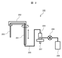
- FIG. 4 is a schematic diagram showing a configuration example of a dispensing unit.
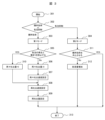
- FIG. 11 is a schematic diagram showing a flow in which a user selects a stirring mode.
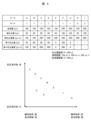
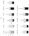
- 11A and 11B are diagrams for explaining the effects and correlations of a first mode and a second mode; Schematic diagram of a two-stage stirring operation in the first mode. Schematic diagram of a single stirring operation in the second mode.
- FIG. 1 is a schematic diagram showing an example of the overall configuration of an automatic analyzer.
- FIG. 4 is a schematic diagram showing a configuration example of a dispensing unit.
- FIG. 11 is a schematic diagram showing a flow in which a user selects a stirring mode.
- 11A and 11B are diagrams for explaining the effects and correlations of a first mode and a second mode; Schematic diagram of a two-stage stirring operation in the first mode. Schematic diagram of a single stirring operation in
- the automatic analyzer is a device that analyzes specific components contained in samples such as blood and urine provided by patients, and has a sample/reagent disk (hereinafter simply referred to as disk) 102, a dispensing unit 105, an incubator (reaction disk) 104, a control unit 106, an input/output unit 107, and a memory unit 108. Each unit will be described below.
- the disk 102 stores the specimen container 100 that contains the specimen and the reagent bottle 101 that contains the reagent, and also transports the specimen container 100 and the reagent bottle 101 to a position that is accessible to the dispensing unit 105.
- the dispensing unit 105 dispenses and mixes specimens and reagents from the specimen containers 100 or reagent bottles 101 into reaction containers 103 stored in the incubator 104. Detailed parameters for dispensing and mixing are controlled by the control unit 106. Note that specimens and reagents may be dispensed by a single dispensing unit 105, or two units, a specimen dispensing unit and a reagent dispensing unit, may be provided and each may be dispensed separately. A more detailed configuration of the dispensing unit 105 will be described later with reference to FIG. 2.
- the incubator 104 stores the reaction vessel 103, which contains a mixture of a sample and a reagent, within a temperature range that allows the mixture to react, and transports the reaction vessel 103 to a position accessible to the dispensing unit 105.
- the reaction vessel 103 By storing the reaction vessel 103 within a predetermined temperature range, the mixture in the reaction vessel 103 becomes the reaction liquid used in the measurement.
- the control unit 106 is a computer that controls the operation of each part.
- the input/output unit 107 is a device that accepts input of data necessary for analysis and displays the results of the analysis, such as a keyboard, mouse, touch panel, or liquid crystal display.
- the storage unit 108 is a device that stores data necessary for analysis and the results of the analysis, such as a HDD (Hard Disk Drive) or SSD (Solid State Drive).
- HDD Hard Disk Drive
- SSD Solid State Drive
- the dispensing unit 105 has a shaft 201, an arm 202, a dispensing probe 203, a syringe pump 204, a tube 205, and an electromagnetic valve 206.
- the shaft 201 is a hollow member that extends vertically and can be moved up and down.
- the arm 202 is a hollow member that extends horizontally, with one end connected to the upper end of the shaft 201 and the other end to which a dispensing probe 203 is attached, and is rotated around the shaft 201 as the axis of rotation. By rotating the arm 202, the dispensing probe 203 is moved directly above the sample container 100 or reagent bottle 101.
- the dispensing probe 203 is a thin tube that is inserted into the sample container 100 or the reagent bottle 101 by the up and down movement of the shaft 201, and its upper end is connected to a tube 205.
- the tube 205 connects the dispensing probe 203 to the syringe pump 204 through the arm 202 and the shaft 201.
- the dispensing probe 203 may be a hollow metal tube, or may have a disposable dispensing tip attached to its tip.
- the syringe pump 204 draws in and pushes out system water in the dispensing probe 203 by driving the plunger 207 in order to aspirate and eject specimens, reagents, and air from the bottom end of the dispensing probe 203.
- Liquids such as specimens and reagents are dispensed by drawing in system water to create negative pressure inside the dispensing probe, and by pushing out system water to create positive pressure inside the dispensing probe.
- the solenoid valve 206 is provided between the syringe pump 204 and a system water container 208 that contains system water, and is closed while a specimen or the like is being dispensed.
- the solenoid valve 206 is opened, and the inner wall of the dispensing probe 203 is washed with system water supplied from the system water container 208, and the inside of the tube 205 is filled with system water.
- the tube 205 before dispensing is filled with system water.
- the liquid that is dispensed is not limited to a reagent, but can also be a specimen or water.
- discharging the liquid into the reaction vessel 103 is called dispensing.
- the dispensing probe 203 is used to simultaneously aspirate liquid A and liquid B.
- the aspirated liquids A and B are discharged again into the reaction vessel. This operation is called re-discharge.
- liquid A and liquid B are mixed together to form a mixed liquid C.
- the series of operations for mixing liquid A and liquid B to form mixed liquid C is called discharging and mixing.
- discharge mixing is that it does not require a dedicated mixing unit to be built into the equipment, which allows for space-saving and cost-saving.
- discharge mixing can have lower mixing efficiency depending on the substance being mixed.
- discharge mixing has sufficient homogenizing ability to mix liquid A and liquid B, when liquid A and liquid B contain bonds of fine molecules (aggregates, etc.), its ability to break apart these bonds may be inferior to other mixing methods.
- the mixed liquid C sucked into the dispensing probe when dispensed into a container, it is dispensed from above the liquid surface in the container.
- a force that shears the aggregates is applied.
- the liquid When dispensing liquid from a dispensing probe, the liquid is generally dispensed with the tip of the dispensing probe below the liquid surface to prevent the liquid from splashing onto the inner wall of the container or introducing air bubbles.
- the liquid is intentionally dispensed from above the liquid surface to apply a shear force to the liquid being stirred.
- the dispensing probe includes a first suction step of aspirating the first agitated liquid (Liquid A) with the dispensing probe, a second suction step of aspirating the second agitated liquid while the first agitated liquid is contained in the dispensing probe, and a first stirring step of discharging the first agitated liquid and the second agitated liquid into a container, characterized in that in the second suction step, air is also aspirated when aspirating the second agitated liquid, and in the first stirring step, the first agitated liquid and the second agitated liquid are discharged into the container above the liquid level of the liquid contained in the container.
- the second feature of this embodiment is that for analysis items in which aggregates are present in the mixed liquid and need to be broken down into smaller particles, the above-mentioned discharge and mixing method is performed, and for analysis items in which no aggregates are present and it is not necessary to apply shear force to the mixed liquid, the liquid is discharged with the tip of the dispensing probe below the liquid surface as in the conventional method, avoiding the entrainment of air bubbles and switching the discharge and mixing method to avoid adverse effects such as splashing of the liquid.
- the following methods are appropriately selected according to the analysis item: 1. Increasing the re-discharge amount, 2. Accelerating the re-discharge speed, and 3. Gas-liquid mixing. 1. The movement of the liquid becomes more dynamic, promoting homogenization of the liquids. 2. Increases the Reynolds number of the liquid, forming turbulence, improving not only the homogenization of the liquids but also the micronization ability. 3. Mixes minute gas particles into the liquid to create a gas-liquid mixture, which increases the shear stress of the turbulence compared to the liquid alone, improving the micronization power of the molecules in the liquid. It is preferable to memorize in advance which of these to execute for each analysis item.
- the parameters of the re-ejection amount, the re-ejection speed, and the number of times of gas-liquid mixing can be expected to have the following effects.
- Increase in re-ejection volume Promotes homogenization of liquids
- Increase in re-ejection speed Promotes homogenization and increases shear stress
- Increase in number of gas-liquid mixings Increases shear stress on aggregates
- the user can select the first stirring mode.
- the first mode is a two-stage stirring operation in which the liquid is discharged into the reaction vessel, the liquid in the reaction vessel is aspirated, the liquid is re-discharged, the liquid is further aspirated again, and the liquid is discharged again. Details of the operation of the first mode will be described later using Figure 5.
- the user can select the second stirring mode.
- the second mode is a one-time stirring operation in which the liquid is discharged into the reaction vessel, the liquid in the reaction vessel is aspirated, the liquid is re-discharged, and then the liquid is not re-aspirated. The operation of the second mode will be described in detail later with reference to Figure 6.
- the re-discharge amount, re-discharge speed, third-re-discharge amount, and third-re-discharge speed can be set arbitrarily in flows 306 to 309. This makes it possible to realize a mixing pattern that corresponds to the mixing difficulty of the analysis item. Note that by increasing the re-discharge amount and third-re-discharge amount, mixing efficiency improves and, conversely, the frequency of air bubble generation increases. By increasing the re-discharge speed and third-re-discharge speed, mixing efficiency improves and, conversely, the frequency of air bubble generation increases.
- the amount of re-re-discharge in the first mode is set to 0 in flow 310. This selects an operation that does not involve re-suction or re-re-discharge, even though it is the first mode.
- the first mode without re-re-discharge is inferior in mixing efficiency to the first mode with re-re-discharge, and is inferior in bubble suppression to the second mode.
- the re-discharge amount and re-discharge speed cannot be set arbitrarily, but are set automatically according to the total liquid volume. This allows for a discharge and stirring operation specialized in bubble suppression. If it is desired to improve the stirring efficiency while increasing bubble suppression in flow 311, the total liquid volume of the reaction liquid is increased in flow 312. Increasing the total liquid volume improves the stirring efficiency, and since the bubble suppression operation is selected according to the total liquid volume, the bubble suppression effect is also maintained.
- Figure 4 shows an example of the relationship between mixing efficiency and bubble suppression effect in the first and second modes.
- the first mode is shown in cases A to G.
- the advantage of the first mode is that it has high mixing efficiency. Two consecutive discharge and mixing operations generate a gas-liquid mixture in the reaction liquid. Molecules that tend to aggregate in the liquid are effectively broken down into smaller particles by the flow in which the shear stress is increased by the gas-liquid mixing, and the effective concentration of molecules that are important in enzyme reactions and antigen-antibody reactions increases, promoting the reaction.
- the shear stress of gas-liquid mixing tends to increase as the third discharge speed is increased.
- the first mode has two weaknesses. The first is that it inevitably introduces air bubbles into the liquid. Depending on the analysis item, air bubbles in the liquid can promote oxidation and inhibit reactions. Also, in analyses involving absorbance measurement, air bubbles can obstruct the light path, making it impossible to measure absorbance correctly.
- the other weakness is that because the discharge and stirring operation is repeated twice, there is more contact with the inner wall of the probe than when the discharge and stirring is performed only once, which can promote contamination of the reaction liquid.
- Case A shows the case in which the total amount of reaction liquid in the first mode is 100 ⁇ L, the re-ejection amount is 30 ⁇ L, the re-ejection speed is 100 ⁇ L/s, the third re-ejection amount is 30 ⁇ L, and the third re-ejection speed is 100 ⁇ L/s.
- the total amount of reaction liquid in the first mode is 100 ⁇ L
- the re-ejection amount is 30 ⁇ L
- the third re-ejection amount is 30 ⁇ L
- the third re-ejection speed is 100 ⁇ L/s.
- Case B shows the case in which the total volume of the reaction liquid in the first mode is 100 ⁇ L, the re-discharge volume is 80 ⁇ L, the re-discharge speed is 100 ⁇ L/s, the third-discharge volume is 80 ⁇ L, and the third-discharge speed is 100 ⁇ L/s.
- the re-discharge volume and third-discharge volume are greater than in case A, so the stirring efficiency is higher and at the same time the frequency of bubble generation increases.
- Case C shows the case in the first mode where the total volume of the reaction liquid is 100 ⁇ L, the re-discharge volume is 80 ⁇ L, the re-discharge speed is 200 ⁇ L/s, the third-discharge volume is 80 ⁇ L, and the third-discharge speed is 200 ⁇ L/s.
- Case C has a faster re-discharge speed and third-discharge speed than case B, so the mixing efficiency is higher and at the same time the frequency of bubble generation increases.
- Case D shows the case in the first mode where the total volume of the reaction liquid is 100 ⁇ L, the re-discharge volume is 80 ⁇ L, the re-discharge speed is 300 ⁇ L/s, the third re-discharge volume is 80 ⁇ L, and the third re-discharge speed is 300 ⁇ L/s.
- Case D has a faster re-discharge speed and third re-discharge speed than case C, so the mixing efficiency is higher and at the same time the frequency of bubble generation increases.
- Case E shows the case in which the total volume of the reaction liquid in the first mode is 100 ⁇ L, the re-ejection volume is 80 ⁇ L, the re-ejection speed is 300 ⁇ L/s, the third-ejection volume is 0 ⁇ L, and the third-ejection speed is 0 ⁇ L/s.
- the second ejection and stirring operation is not performed, so the stirring efficiency is lower than in case D, but the generation of air bubbles can be suppressed and the contamination of the reaction liquid is reduced.
- Case F shows the case in which the total volume of reaction liquid in the first mode is 200 ⁇ L, the re-discharge volume is 160 ⁇ L, the re-discharge speed is 300 ⁇ L/s, the third-discharge volume is 160 ⁇ L, and the third-discharge speed is 300 ⁇ L/s. Since the total volume of liquid in Case F is greater than in Case D, the stirring efficiency is higher and at the same time the frequency of air bubble generation increases. Since the re-discharge volume and third-discharge volume are also increased, the reaction liquid becomes more contaminated than in Case D.
- Case G shows the case in which the total volume of reaction liquid in the first mode is 200 ⁇ L, the re-ejection volume is 160 ⁇ L, the re-ejection speed is 300 ⁇ L/s, the third-ejection volume is 0 ⁇ L, and the third-ejection speed is 0 ⁇ L/s.
- Case E does not perform a second ejection and stirring operation, so the stirring efficiency is lower than in case F, but the generation of air bubbles can be suppressed and contamination of the reaction liquid is reduced.
- the total volume of liquid is increased compared to case E, so the stirring efficiency is improved.
- the second mode is shown in Case H and Case I.
- the advantage of the second mode is that it can suppress the generation of air bubbles in the reaction liquid. By performing a predetermined dispensing and stirring operation once for the total liquid volume, it is possible to dispense and stir without generating air bubbles in the reaction liquid.
- this embodiment has a second mode that prioritizes bubble suppression in addition to the first mode that prioritizes mixing efficiency. This makes it possible to provide an appropriate discharge and mixing operation for analysis items that require bubble suppression.
- the second mode cannot apply a double mixing operation to improve mixing efficiency, the only way to improve mixing efficiency is to increase the total liquid volume. An increase in the total volume of liquid leads to an increase in the amount of reagent used, which has the disadvantage of being poor cost performance.
- Case H shows the case in the second mode where the total volume of the reaction liquid is 100 ⁇ L, the re-discharge volume is 50 ⁇ L, and the re-discharge speed is 200 ⁇ L/s. Although the mixing efficiency is low in case H, the bubble suppression effect is high, and there is little contamination of the reaction liquid.
- Case I shows the case where the total volume of the reaction liquid in the second mode is 100 ⁇ L, the re-ejection volume is 50 ⁇ L, and the re-ejection speed is 200 ⁇ L/s. Case I can achieve higher stirring efficiency than Case H while maintaining the bubble suppression effect of the second mode.
- FIG. 5(a) Liquid 501 is already placed in the reaction vessel 103. Reagent 502 held in the probe 203 is ejected into the reaction vessel 103. The force of the ejection causes some of the reagent 502 and liquid 501 to mix.
- FIG. 5(c) While the probe 203 is raised, the mixed liquid 503 is discharged again into the reaction vessel 103. At this time, the mixed liquid 503 rises along the inner wall of the reaction vessel 103 and then descends due to gravity, causing air to be entrained. As a result, multiple air bubbles 504 are generated in the mixed liquid 503.
- Figure 5(f) The suction of the mixed liquid 503 begins. At this time, the probe 203 immersed in the mixed liquid 503 is controlled to descend while maintaining the length of its immersed tip. A part of the layer of bubbles 504 is sucked into the probe by the flow generated by the re-suction. Finally, the mixed liquid 503 and bubbles 504 are randomly sucked into the inside of the probe 203.
- the microbubbles 505 are repeatedly ejected into the reaction vessel together with the mixed liquid 503. At this time, the mixed liquid 503 is repeatedly ejected from within or from above the bubble layer formed on the liquid surface of the mixed liquid 503, so that an agitated flow of bubbles 504 and microbubbles 505 is formed in the mixed liquid 503.
- the probability of forming the microbubbles 505 depends on the inner diameter of the probe 203 and the re-ejection speed. Since the inner diameter of the probe 203 is uniquely determined by the automatic analyzer, the user can control the generation of the microbubbles 505 by selecting the re-ejection speed within a predefined range.
- FIG. 5(j) The mixed liquid 503 that is ejected again contains microscopic bubbles 505. As the microscopic bubbles move randomly within the reaction vessel, the mixed liquid 503 becomes a gas-liquid mixed state. By becoming a gas-liquid mixture, the shear stress on the molecules in the liquid increases compared to when only the liquid is stirred, and as a result, the ability to atomize the molecules during ejection and stirring is improved.
- the distance between the residual liquid in the reaction vessel and the probe tip is controlled to be greater than in the first mode.
- the discharged mixed liquid spreads out in a fan shape downwards, increasing the contact area between the discharge flow and the residual liquid compared to the first mode. This makes it less likely that liquid will be entrained during re-discharge.
- Re-discharge begins.
- the re-discharge speed is controlled to a flow rate that does not cause liquid entrainment, and the user cannot arbitrarily set the re-discharge amount and re-discharge speed. No air bubbles are present in the mixed liquid during re-discharge.
- 100 sample container, 101: reagent bottle, 102: disk, 103: reaction container, 104: incubator, 105: dispensing unit, 106: control unit, 107: input/output unit, 108: memory unit, 201: shaft, 202: arm, 203: dispensing probe, 204: syringe pump, 205: tube, 206: solenoid valve, 207: plunger, 208: system water container, 501: liquid discharged in advance, 502: reagent, 503: mixed liquid, 504: bubbles, 505: microbubbles, 601: liquid discharged in advance, 602: reagent, 603: mixed liquid
Landscapes
- Physics & Mathematics (AREA)
- Health & Medical Sciences (AREA)
- Life Sciences & Earth Sciences (AREA)
- Chemical & Material Sciences (AREA)
- Analytical Chemistry (AREA)
- Biochemistry (AREA)
- General Health & Medical Sciences (AREA)
- General Physics & Mathematics (AREA)
- Immunology (AREA)
- Pathology (AREA)
- Automatic Analysis And Handling Materials Therefor (AREA)
Abstract
Description
次に吸引した液体Aと液体Bを、反応容器内に再び吐出する。この動作を再吐出という。
これによって該液体Aと該液体Bが混ざり合い、混合液Cとなる。液体Aと液体Bを混ぜ合わせて混合液Cとする一連の動作を吐出攪拌という。
再吐出量増加 :液体同士の均質化が促進される
再吐出速度増加:均質化促進、せん断応力が増加
気液混合回数増加:凝集体へのせん断応力が増加
せん断応力と気泡の混入はトレードオフの関係にある。すなわち、せん断応力を強めたい場合、気泡が混入する。気泡の混入を抑制したい場合、せん断横応力が低下する。
気泡を巻き込むか巻き込まないかの2択だけだと、任意の分析項目を測定する際に、せん断応力と気泡混入において必要十分を満たせない可能性がある。このため、それぞれの分析項目毎にその試薬の性状等に応じて上記パラメータの組み合わせの最適値を求めておき、分析項目毎に事前に設定しておくことが好ましい。
攪拌効率の向上と、2点の弱点はトレードオフの関係にある。この関係について、図4のグラフに示した。
総液量の増加は試薬使用量の増加につながるため、コストパフォーマンスが悪いという弱点がある。
プローブ203の内径は自動分析装置によって一意に決まるため、ユーザは再々吐出速度を予め規定された範囲内で選択することで、微小気泡505の発生を制御することができる。
Claims (10)
- 液体を吸引及び/又は吐出する分注プローブを備えた自動分析装置の液体攪拌方法において、
第一の被攪拌液体を前記分注プローブにより吸引する第一の吸引ステップと、
前記第一の被攪拌液体が前記分注プローブに収容された状態で、第二の被攪拌液体を吸引する第二の吸引ステップと、
前記第一の被攪拌液体と前記第二の被攪拌液体を容器に吐出する第一の攪拌ステップと、を含み、
前記第二の吸引ステップでは前記第二の被攪拌液体の吸引時に空気も併せて吸引し、
前記第一の攪拌ステップでは、前記容器に収容された液体の液面よりも上方で前記第一の被攪拌液体と前記第二の被攪拌液体を該容器に吐出することを特徴とする自動分析装置の液体攪拌方法。 - 請求項1記載の自動分析装置の液体攪拌方法において、
前記第一の吸引ステップと、前記第二の吸引ステップの間に、前記第一の被攪拌液体と前記第二の被攪拌液体が混じり合うことを抑制するための空気相を吸引する分節空気吸引ステップを含むことを特徴とする自動分析装置の液体攪拌方法。 - 請求項1記載の自動分析装置の液体攪拌方法において、
更に前記第一の攪拌ステップで前記容器に吐出された前記第一の被攪拌液体と前記第二の被攪拌液体の混合液を前記分注プローブにより該混合液中の気泡を含むように再度吸引する再吸引ステップと、
前記分注プローブに収容された前記第一の被攪拌液体と前記第二の被攪拌液体の混合液を前記容器に収容された液体の液面よりも上方で該容器に吐出する第二の攪拌ステップと、
を含むことを特徴とする自動分析装置の液体攪拌方法。 - 請求項3記載の自動分析装置の液体攪拌方法において、
前記混合液に割り付けられた分析項目によっては、前記第二の攪拌ステップを行わないことを特徴とする自動分析装置の液体攪拌方法。 - 請求項3記載の自動分析装置の液体攪拌方法において、
前記混合液に割り付けられた分析項目によっては、前記再吸引ステップでの前記第一の被攪拌液体と前記第二の被攪拌液体の混合液の吸引量をゼロとすることを特徴とする自動分析装置の液体攪拌方法。 - 請求項4記載の自動分析装置の液体攪拌方法において、
前記第二の攪拌ステップを行わない場合は、前記第一の攪拌ステップにおいて、
前記第一の吸引ステップでは前記第二の被攪拌液体の吸引時に分注プローブが該第二の被攪拌液体の液面下で前記第二の被攪拌液体を吸引するようにし、
前記第一の攪拌ステップでは、前記容器に収容された液体の液面よりも下方で前記第一の被攪拌液体と前記第二の被攪拌液体を該容器に吐出することを特徴とする自動分析装置の液体攪拌方法。 - 液体を吸引及び/又は吐出する分注プローブを備えた自動分析装置の液体攪拌方法において、
第一の被攪拌液体を前記分注プローブにより吸引する第一の吸引ステップと、
前記第一の被攪拌液体が前記分注プローブに収容された状態で、第二の被攪拌液体を吸引する第二の吸引ステップと、
前記第一の被攪拌液体と前記第二の被攪拌液体を容器に吐出する第一の攪拌ステップと、
前記容器に収容された前記第一の被攪拌液体と前記第二の被攪拌液体の混合液を前記分注プローブにより再度吸引する再吸引ステップと、
前記分注プローブに収容された前記第一の被攪拌液体と前記第二の被攪拌液体の混合液を前記容器に吐出する第二の攪拌ステップと、を含み、
前記第一の被攪拌液体と前記第二の被攪拌液体の総液量、前記第一の攪拌ステップで同時に容器に吐出する前記第一の被攪拌液体と前記第二の被攪拌液体の吐出量、その際の吐出速度、
との関係を予め複数パターン記憶しておき、
前記第一の被攪拌液体に割り付けられた分析項目に応じて、記憶されたいずれのパターンで攪拌を行うか選択することを特徴とする自動分析装置の液体攪拌方法。 - 請求項7記載の自動分析装置の液体攪拌方法において、
更に、
前記容器に収容された前記第一の被攪拌液体と前記第二の被攪拌液体の混合液を前記分注プローブにより再度吸引する再吸引ステップと、
前記分注プローブに収容された前記第一の被攪拌液体と前記第二の被攪拌液体の混合液を前記容器に吐出する第二の攪拌ステップと、を含み、
前記第二の攪拌ステップで同時に容器に吐出する前記第一の被攪拌液体と前記第二の被攪拌液体の吐出量、その際の吐出速度、
との関係も前記第一の攪拌ステップでのパターンに併せて記憶しておき、
前記第一の被攪拌液体に割り付けられた分析項目に応じて、記憶されたいずれのパターンで攪拌を行うか選択することを特徴とする自動分析装置の液体攪拌方法。 - 請求項7または8記載の自動分析装置の液体攪拌方法において、
更に、
前記分注プローブに収容された前記第一の被攪拌液体と前記第二の被攪拌液体の混合液を前記容器に吐出するステップにおいて、
前記容器に混合液を吐出する際の前記分注プローブの収容された混合液の液面からの高さも前記記憶されたパターンに記憶していることを特徴とする自動分析装置の液体攪拌方法。 - 請求項1~8のいずれか一項に記載の自動分析装置の液体攪拌方法が実行されるよう、前記分注プローブを含めた各機構を制御するための制御装置を備えたことを特徴とする自動分析装置。
Priority Applications (3)
| Application Number | Priority Date | Filing Date | Title |
|---|---|---|---|
| JP2025529677A JPWO2025004922A1 (ja) | 2023-06-30 | 2024-06-19 | |
| CN202480009912.7A CN120660002A (zh) | 2023-06-30 | 2024-06-19 | 自动分析装置的液体搅拌方法以及能够执行该方法的自动分析装置 |
| EP24831784.4A EP4737906A1 (en) | 2023-06-30 | 2024-06-19 | Liquid stirring method for automatic analysis device, and automatic analysis device capable of executing same |
Applications Claiming Priority (2)
| Application Number | Priority Date | Filing Date | Title |
|---|---|---|---|
| JP2023107616 | 2023-06-30 | ||
| JP2023-107616 | 2023-06-30 |
Publications (1)
| Publication Number | Publication Date |
|---|---|
| WO2025004922A1 true WO2025004922A1 (ja) | 2025-01-02 |
Family
ID=93938990
Family Applications (1)
| Application Number | Title | Priority Date | Filing Date |
|---|---|---|---|
| PCT/JP2024/022180 Ceased WO2025004922A1 (ja) | 2023-06-30 | 2024-06-19 | 自動分析装置の液体攪拌方法、及び、それを実行可能な自動分析装置 |
Country Status (4)
| Country | Link |
|---|---|
| EP (1) | EP4737906A1 (ja) |
| JP (1) | JPWO2025004922A1 (ja) |
| CN (1) | CN120660002A (ja) |
| WO (1) | WO2025004922A1 (ja) |
Citations (6)
| Publication number | Priority date | Publication date | Assignee | Title |
|---|---|---|---|---|
| JPS6427626A (en) * | 1987-07-21 | 1989-01-30 | Sanuki Kogyo Kk | Method for agitating reagent |
| JP2009533664A (ja) * | 2006-04-11 | 2009-09-17 | ダイアシス ダイアグノスティック システムズ ゲーエムベーハー | 配量および混合方法 |
| JP2011107089A (ja) | 2009-11-20 | 2011-06-02 | Hitachi High-Technologies Corp | 液体混合方法及び分注装置 |
| JP2015132521A (ja) * | 2014-01-10 | 2015-07-23 | 株式会社日立ハイテクノロジーズ | 溶液調製システム |
| WO2019181620A1 (ja) * | 2018-03-19 | 2019-09-26 | 株式会社日立ハイテクノロジーズ | 自動分析装置 |
| WO2021245989A1 (ja) * | 2020-06-01 | 2021-12-09 | 株式会社日立ハイテク | 自動分析装置 |
-
2024
- 2024-06-19 EP EP24831784.4A patent/EP4737906A1/en active Pending
- 2024-06-19 JP JP2025529677A patent/JPWO2025004922A1/ja active Pending
- 2024-06-19 CN CN202480009912.7A patent/CN120660002A/zh active Pending
- 2024-06-19 WO PCT/JP2024/022180 patent/WO2025004922A1/ja not_active Ceased
Patent Citations (6)
| Publication number | Priority date | Publication date | Assignee | Title |
|---|---|---|---|---|
| JPS6427626A (en) * | 1987-07-21 | 1989-01-30 | Sanuki Kogyo Kk | Method for agitating reagent |
| JP2009533664A (ja) * | 2006-04-11 | 2009-09-17 | ダイアシス ダイアグノスティック システムズ ゲーエムベーハー | 配量および混合方法 |
| JP2011107089A (ja) | 2009-11-20 | 2011-06-02 | Hitachi High-Technologies Corp | 液体混合方法及び分注装置 |
| JP2015132521A (ja) * | 2014-01-10 | 2015-07-23 | 株式会社日立ハイテクノロジーズ | 溶液調製システム |
| WO2019181620A1 (ja) * | 2018-03-19 | 2019-09-26 | 株式会社日立ハイテクノロジーズ | 自動分析装置 |
| WO2021245989A1 (ja) * | 2020-06-01 | 2021-12-09 | 株式会社日立ハイテク | 自動分析装置 |
Non-Patent Citations (1)
| Title |
|---|
| See also references of EP4737906A1 |
Also Published As
| Publication number | Publication date |
|---|---|
| CN120660002A (zh) | 2025-09-16 |
| JPWO2025004922A1 (ja) | 2025-01-02 |
| EP4737906A1 (en) | 2026-05-06 |
Similar Documents
| Publication | Publication Date | Title |
|---|---|---|
| JP5024990B2 (ja) | 自動分析装置及びプローブ昇降方法 | |
| US9086395B2 (en) | Automatic analysis apparatus | |
| JP6427573B2 (ja) | 液体攪拌方法 | |
| JP5542379B2 (ja) | 攪拌装置,攪拌方法、および遺伝子自動検査装置 | |
| JP7305891B2 (ja) | 自動分析装置 | |
| WO2019181620A1 (ja) | 自動分析装置 | |
| WO2016132798A1 (ja) | 自動分析装置 | |
| JP2014206381A (ja) | 自動分析装置 | |
| JP7451252B2 (ja) | 自動分析装置 | |
| EP4737906A1 (en) | Liquid stirring method for automatic analysis device, and automatic analysis device capable of executing same | |
| EP3594692B1 (en) | Automatic analysis device and automatic analysis method | |
| JP2011247688A (ja) | 自動分析装置 | |
| JP2021173624A (ja) | 分注装置、自動分析装置、分注方法 | |
| JP5571982B2 (ja) | 自動分析装置 | |
| JP7638302B2 (ja) | 自動分析装置とその制御方法 | |
| JP2012021892A (ja) | 自動分析装置及び分注方法 | |
| WO2025142477A1 (ja) | 自動分析装置、及び自動分析装置の液体攪拌方法 | |
| JP7862159B2 (ja) | 自動分析装置 | |
| JP2010151711A (ja) | 自動分析装置 | |
| JP2005291729A (ja) | 生化学分析装置 | |
| JP2005291727A (ja) | 生化学分析装置 | |
| JPH04291159A (ja) | 自動分析装置の液体分注装置 | |
| JPH02247567A (ja) | 化学分析装置 |
Legal Events
| Date | Code | Title | Description |
|---|---|---|---|
| 121 | Ep: the epo has been informed by wipo that ep was designated in this application |
Ref document number: 24831784 Country of ref document: EP Kind code of ref document: A1 |
|
| ENP | Entry into the national phase |
Ref document number: 2025529677 Country of ref document: JP Kind code of ref document: A |
|
| WWE | Wipo information: entry into national phase |
Ref document number: 2025529677 Country of ref document: JP |
|
| WWE | Wipo information: entry into national phase |
Ref document number: 202480009912.7 Country of ref document: CN |
|
| WWP | Wipo information: published in national office |
Ref document number: 202480009912.7 Country of ref document: CN |
|
| WWE | Wipo information: entry into national phase |
Ref document number: 2024831784 Country of ref document: EP |
|
| NENP | Non-entry into the national phase |
Ref country code: DE |
|
| ENP | Entry into the national phase |
Ref document number: 2024831784 Country of ref document: EP Effective date: 20260130 |
|
| ENP | Entry into the national phase |
Ref document number: 2024831784 Country of ref document: EP Effective date: 20260130 |
|
| WWP | Wipo information: published in national office |
Ref document number: 2024831784 Country of ref document: EP |