WO2025004553A1 - 基板処理方法および基板処理装置 - Google Patents
基板処理方法および基板処理装置 Download PDFInfo
- Publication number
- WO2025004553A1 WO2025004553A1 PCT/JP2024/017305 JP2024017305W WO2025004553A1 WO 2025004553 A1 WO2025004553 A1 WO 2025004553A1 JP 2024017305 W JP2024017305 W JP 2024017305W WO 2025004553 A1 WO2025004553 A1 WO 2025004553A1
- Authority
- WO
- WIPO (PCT)
- Prior art keywords
- substrate
- guard
- liquid
- discharge nozzle
- retention layer
- Prior art date
- Legal status (The legal status is an assumption and is not a legal conclusion. Google has not performed a legal analysis and makes no representation as to the accuracy of the status listed.)
- Ceased
Links
Images






Classifications
-
- H—ELECTRICITY
- H10—SEMICONDUCTOR DEVICES; ELECTRIC SOLID-STATE DEVICES NOT OTHERWISE PROVIDED FOR
- H10P—GENERIC PROCESSES OR APPARATUS FOR THE MANUFACTURE OR TREATMENT OF DEVICES COVERED BY CLASS H10
- H10P52/00—Grinding, lapping or polishing of wafers, substrates or parts of devices
Definitions
- Both the methods and apparatus disclosed herein relate to techniques for processing substrates.
- substrates include semiconductor wafers, glass substrates for liquid crystal display devices, substrates for flat panel displays (FPDs) used in organic electroluminescence (EL) display devices, substrates for optical disks, substrates for magnetic disks, substrates for magneto-optical disks, glass substrates for photomasks, ceramic substrates, substrates for field emission displays (FEDs), and substrates for solar cells.
- the substrate is cleaned before the process.
- cleaning include removing chemicals used in other processes carried out before the process, removing organic residues that are the subject of removal by the chemicals, and removing foreign matter commonly known as particles.
- a layer that holds the particles (tentatively referred to as a "holding layer” below) is first formed on the top surface of the substrate, and then the holding layer is peeled off together with the particles.
- Patent Document 1 exemplifies a process of forming a treatment film having a function similar to that of a retention layer, peeling off the treatment film, and further removing the residue.
- the treatment film is formed by supplying a treatment liquid to a substrate while rotating the substrate, causing the treatment liquid to spread on the substrate by centrifugal force to form a liquid film, and solidifying or curing the liquid film on the substrate.
- the treatment film is peeled off from the substrate by a stripping liquid.
- the residue of the treatment film remaining on the substrate after the treatment film has been removed by the stripping liquid is dissolved and removed by an organic solvent.
- Patent Document 1 discloses a first guard and a second guard that receive liquid splashed outward from the substrate. These guards rise and fall separately between their respective upper and lower positions.
- the first guard surrounds a spin base that rotates the substrate, and is surrounded by the second guard.
- Patent Document 1 does not specify the positions of these guards when a processing liquid, a stripping liquid, or an organic solvent is supplied to the substrate.
- Patent Document 2 was disclosed as a prior art document in Patent Document 1.
- Patent Document 2 discloses a particle retention layer that has a function similar to that of a retention layer.
- the particle retention layer is formed on the upper surface of the substrate by solidifying or curing a treatment liquid.
- the particle retention layer is peeled off by a stripping liquid, and the residue remaining on the substrate after the particle retention layer is removed is removed by a residue removal.
- Patent Document 2 also discloses a first guard and a second guard similar to those in Patent Document 1.
- each of these guards When the processing liquid, the stripping liquid, or the residue removal liquid is supplied to the substrate, each of these guards is positioned in its respective upper position. In this position, the processing liquid, the stripping liquid, and the residue removal liquid that splash outward from the substrate are all received by the first guard.
- Patent document 3 discloses the technology described in the modified embodiment.
- Patent document 2 gives an example of a case where the first guard moves to a lower position, gas is supplied to the substrate, and spin drying is performed.
- the residue removal liquid may be received by the second guard during spin drying.
- the processing liquid, stripping liquid, and residue removal liquid are all received by the first guard, solutes contained in the processing liquid or remaining in the particle retention layer adhere to the first guard. It is expected that the process of removing particles using the particle retention layer (hereinafter also tentatively referred to as the "particle removal process") will be performed multiple times. It is expected that the solutes that adhere to the first guard in the preceding particle removal process will peel off and reach the substrate when processing liquid is supplied to the substrate in the subsequent particle removal process.
- the processing solution supplied to the substrate contains solutes that were originally dissolved in the processing solution (hereinafter also tentatively referred to as “dissolved solutes”; however, in this specification, this also includes dispersed solutes), as well as solutes that peeled off the first guard and adhered to the substrate (hereinafter also tentatively referred to as “peeling solutes”), which solidify or harden to become a retention layer.
- the peeling solutes have a larger particle size than the dissolved solutes, since they were not dissolved or dispersed in the processing solution.
- a retention layer obtained from a processing solution that contains not only dissolved solutes but also peeling solutes has poor flatness, especially on the side that comes into contact with the substrate, compared to a retention layer obtained without the peeling solute. Poor flatness of the retention layer on the side that comes into contact with the substrate leads to poor adhesion between the retention layer and the substrate, which is likely to impair the ability of the retention layer to hold particles on the substrate and remove them from the substrate.
- Patent Document 2 gives an example of heating the processing liquid
- Patent Document 1 gives an example of a case where heating the processing liquid is not necessary. However, it is presumed that the above phenomenon occurs regardless of whether the processing liquid is heated or not.
- the technology disclosed herein was developed in consideration of the anticipated occurrence of the above-mentioned phenomenon, and aims to reduce the occurrence of the solute contained in the treatment liquid for forming the retention layer reaching the substrate separately from the treatment liquid supplied to the substrate.
- the substrate processing method disclosed herein is a method for forming a retention layer on the top surface of the substrate to capture foreign matter on the top surface, and performing a process to remove the foreign matter together with the retention layer, in a substrate processing apparatus that includes a rotation device that rotates a substrate having an upper surface around a vertical axis of rotation, and a first guard that surrounds the rotation device when viewed along the axis of rotation and has a surface facing the rotation device.
- the first aspect of the substrate processing method includes a first step, a second step, and a third step.
- the first step includes: supplying a processing liquid, which includes a solute and a solvent and forms the retention layer by solidification or hardening, to the first upper surface, which is the upper surface of the first substrate; rotating the first substrate to cause a portion of the processing liquid supplied to the first upper surface to scatter outward from the first upper surface; and forming the retention layer on the first upper surface by the solidification or hardening of the processing liquid remaining on the first upper surface.
- the second step is a step of removing the retention layer on the first upper surface.
- the third step includes: supplying a cleaning liquid for cleaning the surface to the second upper surface, which is the upper surface of the second substrate; and rotating the second substrate to cause the cleaning liquid to scatter from the second upper surface to the surface.
- a second aspect of the substrate processing method is the first aspect, in which the substrate processing apparatus further includes a second guard surrounding the first guard when viewed along the rotation axis.
- the first guard can be positioned either at an upper position or at a lower position lower than the upper position.
- the first guard is between the holding position and the second guard when viewed along a direction perpendicular to the rotation axis from the holding position where the rotating device holds the substrate.
- the first guard is positioned at the lower position, the first guard is not between the holding position and the second guard when viewed along the direction.
- the first step the first guard is positioned at the upper position.
- the second step is performed
- the first guard is positioned at the lower position.
- the third step is performed, the first guard is positioned at the upper position.
- a third aspect of the substrate processing method according to the present disclosure is the first or second aspect, in which the third step is performed after the first step and the second step, and the second substrate is the first substrate.
- a fourth aspect of the substrate processing method disclosed herein is the first or second aspect, in which the third step is performed before the first step and the second step, and the second substrate is different from the first substrate.
- a fifth aspect of the substrate processing method according to the present disclosure is any one of the first to fourth aspects, in which the second step includes: removing the retention layer from the first upper surface using a remover; and removing residue from the first upper surface after the retention layer has been removed using a residue removal liquid.
- the residue removal liquid is used as the cleaning liquid.
- a sixth aspect of the substrate processing method according to the present disclosure is any one of the first to fifth aspects, in which in the third step, the cleaning liquid on the second upper surface is dried when or after the second substrate is rotated to splash the cleaning liquid from the second upper surface onto the surface.
- the substrate processing apparatus includes a rotating device that rotates a substrate having an upper surface around a vertical axis of rotation, a first guard that surrounds the rotating device when viewed along the axis of rotation and has a surface facing the rotating device, a second guard that surrounds the first guard when viewed along the axis of rotation, a processing liquid discharge nozzle that is disposed above the rotating device and discharges a processing liquid downward, a stripping liquid discharge nozzle that is disposed above the rotating device and discharges a stripping liquid downward, and a cleaning liquid discharge nozzle that is disposed above the rotating device and discharges a cleaning liquid downward.
- the remover removes the retention layer formed on the first upper surface, which is the upper surface of the first substrate.
- the retention layer is formed on the first upper surface by solidifying or curing the treatment liquid on the first upper surface, and captures foreign matter on the first upper surface.
- the treatment liquid contains a solute and a solvent.
- the first guard when the processing liquid discharge nozzle discharges the processing liquid and supplies it to the first upper surface, and the rotating device rotates the first substrate at a speed at which the processing liquid scatters from the first upper surface, the first guard is located at the upper position.
- the stripping liquid discharge nozzle discharges the stripping liquid and supplies it to the first upper surface
- the rotating device rotates the first substrate at a speed at which the stripping liquid scatters from the first upper surface
- the first guard is located at a lower position below the upper position.
- the cleaning liquid discharge nozzle discharges the cleaning liquid and supplies it to the second upper surface, which is the upper surface of the second substrate, and the rotating device rotates the second substrate at a speed at which the cleaning liquid scatters from the second upper surface, the first guard is located at the upper position.
- the cleaning solution has a component that removes the solute attached to the surface of the first guard facing the rotating device.
- a second aspect of the substrate processing apparatus is the first aspect, further comprising a control device that controls the rotation of the substrate by the rotation device, the position of the first guard, the position of the second guard, the discharge of the processing liquid from the processing liquid discharge nozzle, the discharge of the stripping liquid from the stripping liquid discharge nozzle, and the discharge of the cleaning liquid from the cleaning liquid discharge nozzle.
- the third aspect of the substrate processing apparatus according to the present disclosure is the first or second aspect, in which the second substrate is the first substrate.
- the fourth aspect of the substrate processing apparatus according to the present disclosure is the first or second aspect, in which the second substrate and the first substrate are different.
- a fifth aspect of the substrate processing apparatus is any one of the first to fourth aspects, and includes a residue removal liquid ejection nozzle that ejects a residue removal liquid downward to remove residue on the first upper surface after the retention layer formed on the first upper surface is peeled off.
- the sixth aspect of the substrate processing apparatus is the fifth aspect, in which the residue removal liquid is used as the cleaning liquid, and the residue removal liquid discharge nozzle is also used as the cleaning liquid discharge nozzle.
- the first, third, and fourth aspects of the substrate processing method disclosed herein reduce the occurrence of solutes contained in the processing liquid for forming the retention layer reaching the substrate separately from the processing liquid supplied to the substrate.
- the substrate processing method disclosed herein there is no need to provide a nozzle for discharging the cleaning liquid separately from the nozzle for discharging the residue removal liquid, which reduces the cost of manufacturing the substrate processing apparatus.
- the sixth aspect of the substrate processing method disclosed herein is useful for cleaning the top surface.
- the first, third, and fourth aspects of the substrate processing apparatus disclosed herein reduce the occurrence of solutes contained in the processing liquid for forming the retention layer reaching the substrate separately from the processing liquid supplied to the substrate.
- the second aspect of the substrate processing apparatus disclosed herein contributes to the cooperation of the rotation of the substrate, the arrangement of the first guard and the second guard, the discharge of the processing liquid, the discharge of the stripping liquid, and the discharge of the cleaning liquid.
- the retention layer formed on the upper surface is peeled off, and then the residue on the upper surface is removed.
- FIG. 1 is a plan view illustrating an example of a configuration of a substrate processing apparatus.
- FIG. 2 is a side view illustrating a schematic configuration of a chamber.
- FIG. 2 is a block diagram illustrating a main control system of the substrate processing apparatus.
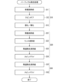
- 1 is a flow chart illustrating a process for cleaning a substrate in a chamber.
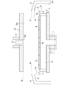
- 5A to 5C are cross-sectional views each showing a schematic example of the state inside a chamber for each process executed in the flowchart of FIG. 4.
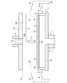
- 5A to 5C are cross-sectional views each showing a schematic example of the state inside a chamber for each process executed in the flowchart of FIG. 4.
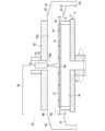
- 5A to 5C are cross-sectional views each showing a schematic example of the state inside a chamber for each process executed in the flowchart of FIG. 4.
- 5A to 5C are cross-sectional views each showing a schematic example of the state inside a chamber for each process executed in the flowchart of FIG. 4.
- 5A to 5C are cross-sectional views each showing a schematic example of the state inside a chamber for each process executed in the flowchart of FIG. 4.
- 5A to 5C are cross-sectional views each showing a schematic example of the state inside a chamber for each process executed in the flowchart of FIG. 4.
- 5A to 5C are cross-sectional views each showing a schematic example of the state inside a chamber for each process executed in the flowchart of FIG. 4.
- 5A to 5C are cross-sectional views each showing a schematic example of the state inside a chamber for each process executed in the flowchart of FIG. 4.
- 5A to 5C are cross-sectional views each showing a schematic example of the state inside a chamber for each process executed in the flowchart of FIG. 4.
- 5A to 5C are cross-sectional views each showing a schematic example of the state
- connection refers to two elements that are in contact with each other, as well as two elements that are separated by another element.
- FIG. 1 is a plan view showing an example of the configuration of a substrate processing apparatus 1.
- the substrate processing apparatus 1 is a single-wafer processing apparatus that processes substrates W, which are to be processed, one by one.
- the substrates W are semiconductor substrates having a substantially circular disk shape.
- the substrate W is not necessarily limited to a semiconductor substrate.
- various substrates such as a glass substrate for a photomask, a glass substrate for a liquid crystal display, a glass substrate for a plasma display, a substrate for an FED (Field Emission Display), a substrate for an optical disk, a substrate for a magnetic disk, and a substrate for a magneto-optical disk can be used as the substrate W.
- the shape of the substrate is also not limited to a disk shape, and various shapes such as a rectangular plate shape can be used.
- the substrate processing apparatus 1 includes a load port 105, an indexer section 103, a processing section 102, a transfer section 104, a transport section 106, and a controller 107.
- the controller 107 comprehensively controls the operations of the components of the substrate processing apparatus 1 other than the controller 107.
- the processing section 102 has multiple, for example, four, towers 20. In a plan view, the four towers 20 are arranged around the transport section 106. Each tower 20 has multiple, for example, three, chambers 2 stacked vertically in a plan view. The chambers 2 function as processing chambers for processing the substrates W.
- the carriers C are loaded into the load port 105.
- the carriers C may be FOUPs (Front Opening Unified Pods) that store substrates W in an enclosed space, SMIF (Standard Mechanical Interface Face) pods, or OCs (Open Cassettes) that expose substrates W to the outside air.
- FOUPs Front Opening Unified Pods
- SMIF Standard Mechanical Interface Face
- OCs Open Cassettes
- the substrate processing apparatus 1 includes an indexer robot 109.
- the indexer robot 109 moves mainly along the direction in which the carriers C are lined up in the indexer section 103 (see arrow F1 in FIG. 1).
- the indexer robot 109 moves between the indexer section 103 and the transfer section 104 (see arrow F2 in FIG. 1).
- the indexer robot 109 has the function of holding substrates W.
- the indexer robot 109 transports substrates W between the carriers C in the indexer section 103.
- the substrate processing apparatus 1 includes a transport robot 108.
- the transport robot 108 has a function of holding the substrate W.
- the transport robot 108 moves between the delivery section 104 and the transport section 106 (see arrow F3 in FIG. 1).
- the transport robot 108 transports the substrate W between the indexer robot 109 in the transfer section 104.
- the indexer robot 109 transports the substrate W between the transport robot 108 in the transfer section 104.
- the transport robot 108 moves between the transport section 106 and each of the chambers 2 (see arrow F4 in FIG. 1).
- the transport robot 108 transfers substrates W between each of the chambers 2.
- the transport robot 108 receives the substrate W from the indexer robot 109 and transports it into one of the chambers 2.
- the transport robot 108 transports the processed substrate W out of the chamber 2 and hands it over to the indexer robot 109.
- Configuration of chamber 2 2 is a side view illustrating a schematic configuration of the chamber 2.
- the chamber 2 has a spin chuck 4, a processing liquid discharge nozzle 5, a stripping liquid discharge nozzle 6, a processing cup 40, an opposing member 50, a gas discharge nozzle 60, a rinsing liquid discharge nozzle 65, and a residue removal liquid discharge nozzle 7.
- the spin chuck 4 has the function of holding a single substrate W to be processed in a horizontal position and rotating it around a vertical rotation axis A1.
- the substrate W held by the spin chuck 4 rotates around the rotation axis A1 as the spin chuck 4 rotates.
- the substrate W is held horizontally by the spin chuck 4 with its center positioned on the rotation axis A1.
- the spin chuck 4 functions as a rotation device that rotates the substrate W to be processed around the rotation axis A1.
- the spin chuck 4 includes a chuck pin 8, a spin base 9, a rotating shaft 10, and a spin motor 11.
- the spin motor 11 has the function of rotating the rotating shaft 10 about the rotation axis A1.
- the rotating shaft 10 extends vertically along the rotation axis A1 and is, for example, a hollow shaft. The upper end of the rotating shaft 10 is connected to the center of the lower surface of the spin base 9.
- the spin base 9 has a disk shape that extends horizontally.
- a plurality of chuck pins 8 are arranged at intervals in the circumferential direction on the periphery of the upper surface 9a of the spin base 9. The chuck pins 8 grip the substrate W above the spin base 9 and release the grip of the substrate W.
- the chuck pin 8 is fixed above the spin base 9 and functions as an end of the spin chuck 4 that holds the substrate W above the spin base 9.
- the position 8a of the upper end of the chuck pin 8 can be considered an example of a holding position where the spin chuck 4 holds the substrate W.
- the chuck pins 8 grip the substrate W, the spin motor 11 applies a rotational force to the rotating shaft 10, and the spin base 9 rotates, causing the substrate W to rotate about the rotation axis A1.
- the processing liquid discharge nozzle 5 is disposed above the spin chuck 4.
- the processing liquid discharge nozzle 5 has the function of discharging the processing liquid downward.
- this function allows the processing liquid discharge nozzle 5 to supply processing liquid to the upper surface Wa of the substrate W.
- the processing liquid contains a solute and a volatile solvent, and solidifies or hardens to become a retention layer.
- the remover liquid discharge nozzle 6 is disposed above the spin chuck 4.
- the remover liquid discharge nozzle 6 has the function of discharging the remover liquid downward.
- the remover liquid discharge nozzle 6 can be said to have the function of supplying the remover liquid to the upper surface Wa by this function.
- the remover liquid peels off the retention layer from the substrate W, as described in detail later.
- the processing liquid discharge nozzle 5 is moved by a nozzle movement mechanism 12.
- the nozzle movement mechanism 12 moves the processing liquid discharge nozzle 5, for example, between a central position and a retracted position, in a horizontal direction, for example, along a direction perpendicular to the rotation axis A1.
- the nozzle movement mechanism 12 is provided, for example, in the chamber 2.
- the central position of the processing liquid discharge nozzle 5 coincides with the rotation axis A1 in a plan view, for example.
- the processing liquid discharge nozzle 5 faces, for example, the center of rotation of the upper surface Wa.
- the processing liquid discharge nozzle 5 When the processing liquid discharge nozzle 5 is in the retracted position, it does not face the upper surface Wa of the substrate W when it is held by the spin chuck 4. For example, the retracted position is outside the spin base 9 in a plan view.
- a processing liquid supply pipe 13 is connected to the processing liquid discharge nozzle 5.
- a valve 14 is provided in the processing liquid supply pipe 13. Processing liquid is supplied to the processing liquid supply pipe 13 from the opposite side of the valve 14 to the processing liquid discharge nozzle 5 by a mechanism (not shown).
- the valve 14 adjusts the flow rate of the processing liquid flowing through the processing liquid supply pipe 13, and typically opens and closes the flow path of the processing liquid supply pipe 13.
- the valve 14 is provided in the chamber 2, for example.
- the stripping solution discharge nozzle 6 is moved by a nozzle movement mechanism 15.
- the nozzle movement mechanism 15 moves the stripping solution discharge nozzle 6, for example, between a central position and a retracted position, in a horizontal direction, for example, a direction perpendicular to the rotation axis A1.
- the nozzle movement mechanism 15 is provided, for example, in the chamber 2.
- the central position of the stripping solution discharge nozzle 6 coincides with the rotation axis A1 in a plan view, for example.
- the stripping solution discharge nozzle 6 faces, for example, the center of rotation of the upper surface Wa.
- the stripping solution discharge nozzle 6 When the stripping solution discharge nozzle 6 is in the retracted position, it does not face the upper surface Wa when the substrate W is held by the spin chuck 4.
- the retracted position of the stripping solution discharge nozzle 6 is outside the spin base 9 in a plan view, and is different from the retracted position of the processing solution discharge nozzle 5.
- a remover liquid supply pipe 16 is connected to the remover liquid discharge nozzle 6.
- a valve 17 is provided in the remover liquid supply pipe 16.
- the remover liquid is supplied to the remover liquid supply pipe 16 from the opposite side of the valve 17 to the remover liquid discharge nozzle 6 by a mechanism (not shown).
- the valve 17 adjusts the flow rate of the processing liquid flowing through the remover liquid supply pipe 16, and typically opens and closes the flow path of the remover liquid supply pipe 16.
- the valve 17 is provided in the chamber 2, for example.
- the processing cup 40 includes guards 41 and 42, cups 45 and 46, and an outer wall member 43.
- the guards 41 and 42 have the function of receiving liquid that splashes outward from the substrate W (more specifically, the upper surface Wa) held by the spin chuck 4.
- the cup 45 receives the liquid guided downward by the guard 41.
- the cup 46 receives the liquid guided downward by the guard 42.
- the liquid received by the cups 45 and 46 may be recovered, for example, by a known recovery mechanism (not shown) and reused. Such reuse contributes to reducing the usage of the processing liquid, stripping liquid, and also the residue removal liquid and rinsing liquid described below. Such reduction in usage contributes to cost reduction.
- Guard 41 surrounds the outside of spin chuck 4 and is, for example, cylindrical. Guard 41 surrounds spin chuck 4 when viewed along rotation axis A1. Guard 42 surrounds the outside of guard 41 and is, for example, cylindrical. Guard 42 surrounds guard 41 when viewed along rotation axis A1.
- Cup 45 surrounds the outside of spin chuck 4 on the side closer to spin chuck 4 than guard 41, and has a groove shape that opens upward.
- Cup 46 surrounds the outside of guard 41 on the side opposite to spin chuck 4 than guard 41, and has a groove shape that opens upward below guard 42.
- cups 45 and 46 are connected to guard 41.
- Guards 41, 42 are raised and lowered separately by a guard lifting mechanism 44.
- the guard lifting mechanism 44 raises and lowers guard 41 between an upper position and a lower position that is lower than the upper position.
- Guard 41 can be positioned in either its upper position or its lower position.
- the guard lifting mechanism 44 raises and lowers guard 42 between an upper position and a lower position that is lower than the upper position.
- Guard 42 can be positioned in either its upper position or its lower position.
- the guard lifting mechanism 44 is provided, for example, in chamber 2.
- guard 41 When guard 42 is in its lower position, guard 41 is also in its lower position, and the upper ends of guards 41 and 42 are lower than position 8a, which is the holding position. Setting guards 41 and 42 to the lower position in this manner facilitates attachment and detachment of substrate W to and from spin chuck 4.
- guard 41 can be in any position from the upper position to the lower position.
- guards 41, 42 are in their respective upper positions and liquid splashes outward from the upper surface Wa of the substrate W held by the spin chuck 4, the splashed liquid is mainly received by guard 41.
- guard 41 is in its upper position and guard 41 is in its lower position and liquid splashes outward from the upper surface Wa of the substrate W held by the spin chuck 4, the splashed liquid is mainly received by guard 42.
- the guard lifting mechanism 44 is realized, for example, by using a ball screw mechanism attached to the guard 41 and a motor that provides driving force to the ball screw mechanism (neither shown), and a ball screw mechanism attached to the guard 42 and a motor that provides driving force to the ball screw mechanism (neither shown).
- the outer wall member 43 surrounds the guards 41, 42 and the cups 45, 46 from the outside and has, for example, a cylindrical shape.
- the opposing member 50 is provided above the spin chuck 4.
- the opposing member 50 includes an opposing surface 50a that faces the spin base 9, more specifically, the upper surface 9a.
- the opposing surface 50a is positioned approximately horizontally.
- the opposing surface 50a faces, for example, the substrate W held by the spin chuck 4, and has a disk shape having approximately the same diameter as the substrate W or a diameter larger than the substrate W.
- a hollow shaft 51 is fixed to the opposing member 50 on the side opposite the opposing surface 50a.
- a communication hole 50b is formed in the opposing member 50.
- the communication hole 50b passes through the opposing member 50 from top to bottom and communicates with the internal space of the hollow shaft 51.
- the communication hole 50b and the hollow shaft 51 overlap with the rotation axis A1.
- the opposing member 50 is raised and lowered by an opposing member lifting mechanism 52.
- the opposing member lifting mechanism 52 has the function of positioning the opposing member 50 at any position (height) between the upper position and the lower position.
- the opposing member lifting mechanism 52 is provided in, for example, the chamber 2.
- the lower position of the opposing member 50 is the position where the opposing surface 50a is closest to the upper surface 9a within the movable range of the opposing member 50.
- the opposing surface 50a is higher than the upper surface Wa.
- the upper position of the opposing member 50 is the position where the opposing surface 50a is furthest from the upper surface 9a within the movable range of the opposing member 50.
- the upper position of the opposing member 50 can also be seen as the retracted position of the opposing member 50.
- the opposing member lifting mechanism 52 is realized, for example, by using a support member (not shown) that supports the hollow shaft 51, a ball screw mechanism (not shown) attached to the support member, and an electric motor (not shown) that provides a driving force to the ball screw mechanism.
- the residue removal liquid discharge nozzle 7, the gas discharge nozzle 60, and the rinsing liquid discharge nozzle 65 are all positioned above the spin chuck 4. Specifically, the residue removal liquid discharge nozzle 7, the gas discharge nozzle 60, and the rinsing liquid discharge nozzle 65 are all housed in a nozzle housing member 53. The nozzle housing member 53 is inserted into the hollow shaft 51.
- the respective outlets of the residue removal liquid discharge nozzle 7, the gas discharge nozzle 60 and the rinsing liquid discharge nozzle 65 are exposed downward from the lower end of the nozzle housing member 53.
- the lower end of the nozzle housing member 53 faces the center of the upper surface 9a in a plan view.
- the respective outlets of the residue removal liquid discharge nozzle 7, the gas discharge nozzle 60 and the rinsing liquid discharge nozzle 65 face approximately the center of the upper surface Wa.
- the residue removal liquid discharge nozzle 7 has the function of discharging the residue removal liquid downward.
- this function can be said to allow the residue removal liquid discharge nozzle 7 to supply the residue removal liquid to the upper surface Wa of the substrate W.
- this residue removal liquid removes residue on the upper surface Wa after the retention layer has been peeled off.
- the gas discharge nozzle 60 has the function of discharging gas downward. When the substrate W is held by the spin chuck 4, this function allows the gas discharge nozzle 60 to supply gas to the upper surface Wa of the substrate W. As will be described in detail later, the gas is used to solidify or harden the processing liquid, or to dry the upper surface Wa after the residue has been removed.
- the rinse liquid discharge nozzle 65 has the function of discharging rinse liquid downward. When the substrate W is held by the spin chuck 4, this function allows the rinse liquid discharge nozzle 65 to supply rinse liquid to the upper surface Wa of the substrate W. As will be described in detail later, this rinse liquid is used to clean the upper surface Wa after the retention layer has been peeled off and before the residue on the upper surface Wa is removed.
- a residue removal liquid supply pipe 22 is connected to the residue removal liquid discharge nozzle 7.
- a valve 23 is provided to the residue removal liquid supply pipe 22. Residue removal liquid is supplied to the residue removal liquid supply pipe 22 from the opposite side of the valve 23 to the residue removal liquid discharge nozzle 7 by a mechanism (not shown).
- the valve 23 adjusts the flow rate of the residue removal liquid flowing through the residue removal liquid discharge nozzle 7, and typically opens and closes the flow path of the residue removal liquid supply pipe 22.
- the valve 23 is provided, for example, in the chamber 2.
- a gas supply pipe 61 is connected to the gas discharge nozzle 60.
- a valve 62 is provided on the gas supply pipe 61. Gas is supplied to the gas supply pipe 61 from the opposite side of the valve 62 to the gas discharge nozzle 60 by a mechanism (not shown).
- the valve 62 adjusts the flow rate of gas flowing through the gas discharge nozzle 60, and typically opens and closes the flow path of the gas supply pipe 61.
- the valve 62 is provided, for example, in the chamber 2.
- a rinsing liquid supply pipe 66 is connected to the rinsing liquid discharge nozzle 65.
- a valve 67 is provided on the rinsing liquid supply pipe 66. Rinse liquid is supplied to the rinsing liquid supply pipe 66 from the opposite side of the valve 67 to the rinsing liquid discharge nozzle 65 by a mechanism (not shown).
- the valve 67 adjusts the flow rate of the rinsing liquid flowing through the rinsing liquid discharge nozzle 65, and typically opens and closes the flow path of the rinsing liquid supply pipe 66.
- the valve 67 is provided in the chamber 2, for example.
- Control System of Substrate Processing Apparatus 1 3 is a block diagram illustrating a main control system of the substrate processing apparatus 1.
- the control device 107 includes a processor 3A and a memory 3B.
- the memory 3B stores a control program.
- the control program is executed by the processor 3A to control the operation of the substrate processing apparatus 1.
- the processor 3A and the memory 3B are realized by a microcomputer.
- the processor 3A is composed of, for example, one or more central processing units (CPUs).
- the memory 3B is composed of, for example, a volatile storage medium such as a random access memory (RAM) and a non-volatile storage medium such as a hard disk drive (HDD) or a solid state drive (SSD).
- the non-volatile storage medium can store, for example, the above-mentioned control program as well as various other information.
- the processor 3A executes the control program, the RAM is used, for example, as a workspace, and stores information that is temporarily generated or acquired. At least a portion of the functions realized by the control device 107 may be realized by hardware such as a dedicated electronic circuit.
- control device 107 controls the spin motor 11, the nozzle movement mechanisms 12 and 15, the opposing member lifting mechanism 52, the guard lifting mechanism 44, and the valves 14, 17, 23, 62, and 67.
- Such control is represented by solid arrows in FIG. 3.
- the spin base 9 is driven to rotate by a spin motor 11.
- the processing solution discharge nozzle 5 is moved by a nozzle movement mechanism 12.
- the stripping solution discharge nozzle 6 is moved by a nozzle movement mechanism 15.
- the opposing member 50 is raised and lowered by an opposing member lifting mechanism 52.
- the guards 41, 42 are raised and lowered by a guard lifting mechanism 44. The mechanical connections between these are represented by dashed arrows in Figures 1 and 3.
- the control device 107 may not be provided in the substrate processing apparatus 1, but may be provided outside the substrate processing apparatus 1.
- the processor 3A may be provided in the substrate processing apparatus 1, and the memory 3B may be provided outside the substrate processing apparatus 1.
- the memory 3B may be provided in the substrate processing apparatus 1, and the processor 3A may be provided outside the substrate processing apparatus 1. It is clear that the control system illustrated in FIG. 3 can be realized in these cases as well.
- FIG. 4 is a flow chart illustrating a process of cleaning the substrate W in the chamber 2. Specifically, Fig. 4 illustrates a process of removing particles (foreign matter) on the upper surface Wa, and the flow chart is entitled "Particle Removal Process.” When the particle removal process is started, the substrate W to be cleaned is already held by the spin chuck 4.
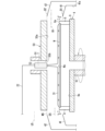
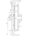
- FIGS. 5 to 13 are cross-sectional views that show schematic examples of the conditions inside chamber 2 for each step performed in the flowchart.
- Step S10 is a process for forming a retention layer on the upper surface Wa.
- Step S20 is a process for removing the retention layer together with the particles.
- Step S30 is a process for removing solutes adhering to the guard 42.
- Step S10 includes steps S11, S12, and S13, which are performed in this order.
- Step S11 is a step of supplying a processing liquid to the upper surface Wa.
- Step S12 is a step commonly known as spin-off, in which a portion of the processing liquid is scattered outward from the upper surface Wa, leaving an appropriate amount of the processing liquid on the upper surface Wa.
- Step S13 is a step of forming a retention layer by solidifying or curing the processing liquid (denoted as "solidifying/curing" in FIG. 4).
- FIG. 5 is a schematic diagram illustrating the situation inside the chamber 2 when step S11 is performed.
- the guard lifting mechanism 44 positions both guards 41 and 42 at their respective upper positions U1 and U2 (both guards 41 and 42 are located at their respective upper positions U1 and U2).
- the upper position U1 of the guard 41 is shown as the vertical position of the upper end of the guard 41.
- the upper position U2 of the guard 42 is shown as the vertical position of the upper end of the guard 42.
- guards 41 and 42 are shown bent toward the spin chuck 4, but such bending is not necessarily required.
- guard 42 has a cylindrical shape that maintains its diameter in the vertical direction, it is not necessarily required that upper position U2 be higher than upper position U1.
- step S11 When step S11 is performed at the upper end of the guard 41, the spin motor 11 rotates the spin base 9, and thus the substrate W.
- the rotation speed is, for example, 10 rpm to several tens of rpm.
- step S11 the opposing member 50 is positioned at its upper position U5 by the opposing member lifting mechanism 52 (the opposing member 50 is positioned at the upper position U5).
- the upper position U5 of the opposing member 50 is shown as the vertical position of the opposing surface 50a.
- the nozzle movement mechanism 12 positions the processing liquid discharge nozzle 5 at its central position (the processing liquid discharge nozzle 5 is located at its central position).
- the valve 14 opens and the processing liquid 27 is discharged from the processing liquid discharge nozzle 5 and supplied to the upper surface Wa.
- the processing liquid 27 supplied to the upper surface Wa spreads over almost the entire surface of the upper surface Wa due to centrifugal force.
- step S11 After the treatment liquid 27 has been supplied to the upper surface Wa for a predetermined time, the valve 14 is closed and step S11 is completed. After step S11 is completed, step S12 is executed.
- FIG. 6 illustrates a schematic example of the situation inside the chamber 2 when step S12 is performed.
- step S12 both guards 41 and 42 remain in their respective upper positions U1 and U2.
- the spin motor 11 rotates the spin base 9 and thus the substrate W.
- the rotation speed is, for example, 300 rpm to 1500 rpm. Rotation at such a speed causes the processing liquid 27 to splash from the upper surface Wa.
- step S12 the opposing member 50 remains in its upper position U5.
- the nozzle moving mechanism 12 moves the processing liquid discharge nozzle 5 to its retracted position (the processing liquid discharge nozzle 5 is in its retracted position: not shown).
- step S11 By adjusting the amount of treatment liquid 27 supplied in step S11 and the speed and time at which the substrate W rotates in step S12, an appropriate amount of treatment liquid 27 for forming a retention layer 29 is left on the upper surface Wa, while excess treatment liquid 27 is splashed outward from the periphery of the upper surface Wa and removed.
- the guard 41 located at the upper position U1 is between position 8a and the guard 42.
- the processing liquid 27 scattered from the upper surface Wa is received by the guard 41, specifically, by the surface 41a of the guard 41 facing the spin chuck 4, and adhesion of the processing liquid 27 to the guard 42 is suppressed. At this time, volatilization of volatile components contained in the processing liquid 27, such as the solvent, may proceed.
- step S12 the substrate W rotates and a predetermined time elapses before step S12 is completed. After step S12 is completed, step S13 is executed.
- FIG. 7 illustrates a schematic diagram of the situation inside the chamber 2 when step S13 is performed.
- step S13 When step S13 is performed, both guards 41, 42 remain in their respective upper positions U1, U2.
- the spin motor 11 rotates the spin base 9, and thus the substrate W.
- the rotation speed is, for example, 100 rpm to 1000 rpm.
- step S13 the opposing member 50 is in its lower position D5. In FIGS. 5 to 13, the lower position D5 of the opposing member 50 is shown as the vertical position of the opposing surface 50a.
- step S13 the valve 62 opens, and gas is discharged from the gas discharge nozzle 60 and supplied between the opposing surface 50a and the upper surface Wa.
- Nitrogen gas for example, is used as the gas.
- step S13 the volatilization of the volatile components, such as the solvent, progresses, and the treatment liquid 27 solidifies or hardens. This solidification or hardening forms a solid retention layer 29 on the upper surface Wa, the main component of which is a solute.
- the retention layer 29 is formed, particles (not shown) that were attached to the upper surface Wa are detached from the upper surface Wa and are retained in the retention layer 29.
- solidification refers to the solidification of a solute due to forces acting between molecules or atoms as the solvent evaporates, for example.
- Harddening refers to the solidification of a solute due to chemical changes such as polymerization or crosslinking, for example. Therefore, “solidification or hardening” refers to the “solidification” of a solute due to various factors. Note that it is sufficient for the processing liquid 27 to solidify or harden to an extent that it can hold particles, and it is not necessary for the solvent to evaporate completely.
- the solute and solvent contained in the treatment liquid 27 may be various substances, taking into consideration the material of the substrate W.
- solutes include acrylic resin, phenol resin, epoxy resin, melamine resin, urea resin, unsaturated polyester resin, alkyd resin, polyurethane, polyimide, polyethylene, polypropylene, polyvinyl chloride, polystyrene, polyvinyl acetate, polytetrafluoroethylene, acrylonitrile butadiene styrene resin, acrylonitrile styrene resin, polyamide, polyacetal, polycarbonate, polyvinyl alcohol, modified polyphenylene ether, polybutylene terephthalate, polyethylene terephthalate, polyphenylene sulfide, polysulfone, polyether ether ketone, and polyamide imide. From these examples, the solute in this embodiment may be selected.
- the solute may be an organic compound other than a resin, or a mixture of an organic compound other than
- step S13 After the gas supply is performed in step S13 (specifically, after valve 62 is opened), a predetermined time elapses, the gas supply stops (specifically, valve 62 is closed), and step S13 is completed. After step S13 is completed, step S20 is executed.
- Step S20 includes steps S21, S22, S23, and S24, which are performed in this order.
- Step S21 is a step of peeling off the retention layer 29 using a stripping solution.
- Step S22 is a step of washing off the stripping solution and the stripped retention layer 29 from the upper surface Wa.
- Step S23 is a step of removing residue remaining on the upper surface Wa by step S22.
- Step S24 is a step of performing spin drying.
- Figure 8 illustrates a schematic diagram of the situation inside the chamber 2 when step S21 is performed.
- the guard lifting mechanism 44 positions the guard 41 at its lower position D1 while the guard 42 is positioned at its upper position U2.
- the lower position D1 is lower than the upper position U1.
- the lower position D1 of the guard 41 is shown as the vertical position of the upper end of the guard 41.
- step S21 the spin motor 11 rotates the spin base 9, and thus the substrate W.
- the rotation speed is, for example, 500 rpm to 800 rpm.
- step S21 the opposing member lifting mechanism 52 positions the opposing member 50 at its upper position U5 (the opposing member 50 is located at the upper position U5).
- the nozzle moving mechanism 15 positions the remover liquid discharge nozzle 6 at its central position (the remover liquid discharge nozzle 6 is positioned at its central position).
- the valve 17 opens and the remover liquid 32 is discharged from the remover liquid discharge nozzle 6 and supplied to the retention layer 29.
- the remover liquid 32 supplied to the retention layer 29 spreads over almost the entire upper surface of the retention layer 29 due to the action of centrifugal force.
- the retention layer 29 is peeled off from the upper surface Wa by the removal liquid 32 supplied.
- the rotation at the above-mentioned speed causes the remover liquid 32 to splash from the upper surface Wa.
- the peeled retention layer 29 splashes outward from the periphery of the upper surface Wa together with the remover liquid 32.
- the guard 41 located at lower position D1 is not between position 8a and the guard 42.
- the retention layer 29 and the stripping liquid 32 scattered from the upper surface Wa pass over the top of the guard 41 and are received by the guard 42.
- the solutes contained in the retention layer 29, or more specifically, the processing liquid 27, are prevented from adhering to the surface 41a of the guard 41.
- the remover 32 is compatible with the solvent, and the solute is poorly soluble or insoluble in the remover 32.
- the remover 32 penetrates into the retention layer 29 through interaction with the solvent remaining in the retention layer 29, and reaches the upper surface Wa.
- the remover 32 does not easily dissolve the solute, which is the main component of the retention layer 29. Particles that have been taken up into the retention layer 29 are removed from the upper surface Wa together with the retention layer 29, and are removed from the upper surface Wa.
- PGEE propylene glycol monoethyl ether
- SC1 a mixed acid containing ammonium hydroxide and hydrogen peroxide
- step S21 After the supply of stripping liquid 32 in step S21 (specifically, after valve 17 opens), a predetermined time elapses, the supply of stripping liquid 32 stops (specifically, valve 17 closes), and step S21 is completed. After step S21 is completed, step S22 is executed.
- step S22 illustrates a schematic diagram of the state inside the chamber 2 when step S22 is performed.
- the guard 42 remains in its upper position U2, and the guard 41 remains in its lower position D1.
- the spin motor 11 rotates the spin base 9, and thus the substrate W.
- the rotation speed is, for example, 100 rpm to 1000 rpm.
- the nozzle moving mechanism 15 positions the stripping solution discharge nozzle 6 in its retracted position (the stripping solution discharge nozzle 6 is in its retracted position: not shown). After the stripping solution discharge nozzle 6 is in its retracted position, the opposing member 50 is lowered by the opposing member lifting mechanism 52 to a middle position M5.
- the middle position M5 of the opposing member 50 is lower than the upper position U5 of the opposing member 50 and higher than the lower position D5 of the opposing member 50.
- the middle position M5 is shown as the vertical position of the opposing surface 50a.
- step S22 after the stripping liquid discharge nozzle 6 is positioned at its retracted position, the valve 67 opens while the substrate W is rotating at the above-mentioned speed, and the rinsing liquid 31 is discharged from the rinsing liquid discharge nozzle 65 and supplied to the upper surface Wa.
- the discharge of the rinsing liquid 31 from the rinsing liquid discharge nozzle 65 begins, for example, when the opposing member 50 is in the middle position M5.
- the discharge may begin when the opposing member 50 is in its upper position U5, or may begin while the opposing member 50 is moving from its upper position U5 to the middle position M5.
- the rinsing liquid 31 supplied to the upper surface Wa spreads over almost the entire surface of the upper surface Wa due to the action of centrifugal force, and is then scattered outward from the periphery of the upper surface Wa.
- the rinsing liquid 31 washes away the stripping liquid 32 remaining on the upper surface Wa, and further the retention layer 29 remaining on the upper surface Wa after it has been stripped, from the upper surface Wa.
- the scattered rinsing liquid 31, stripping liquid 32, and further the retention layer 29 are received by the guard 42.
- the solutes contained in the retention layer 29, or more specifically, the processing liquid 27, are prevented from adhering to the surface 41a of the guard 41.
- Examples of the rinse liquid 31 include DIW, carbonated water, electrolytic ionized water, hydrogen water, ozone water, and hydrochloric acid water with a diluted concentration (e.g., about 10 ppm to 100 ppm).
- step S22 After the supply of rinsing liquid 31 in step S22 (specifically, after valve 67 opens), a predetermined time elapses, the supply of rinsing liquid 31 stops (specifically, valve 67 closes), and step S21 is completed. After step S21 is completed, step S23 is executed.
- FIG. 10 illustrates a schematic diagram of the situation inside the chamber 2 when step S23 is performed.
- the guard 42 remains in its upper position U2, and the guard 41 remains in its lower position D1.
- the spin motor 11 rotates the spin base 9, and thus the substrate W.
- the rotation speed is, for example, several tens of rpm to 300 rpm.
- the opposing member 50 remains in the middle position M5.
- step S23 while the substrate W is rotating at the above-mentioned speed, the valve 23 opens, and the residue removal liquid 33 is discharged from the residue removal liquid discharge nozzle 7 and supplied to the upper surface Wa.
- the residue removal liquid 33 supplied to the upper surface Wa spreads over almost the entire surface of the upper surface Wa by centrifugal force.
- the rinsing liquid 31 remaining on the upper surface Wa is replaced with the residue removal liquid 33.
- the residue removal liquid 33 dissolves the residue of the retention layer 29 remaining on the upper surface Wa.
- the stripping liquid 32 is scattered outward from the periphery of the upper surface Wa by the rotation at the above-mentioned speed (for example, 500 rpm to 800 rpm).
- the scattered residue removal liquid 33 and residue are received by the guard 42.
- the solute contained in the retention layer 29, more specifically the processing liquid 27, is prevented from adhering to the surface 41a of the guard 41.
- a solvent that has the ability to dissolve the solute is used for the residue removal liquid 33.
- Patent Document 2 lists thinner, toluene, acetate esters, alcohols, and glycols as examples of solvents that correspond to the residue removal liquid 33 of this embodiment. From these examples, the residue removal liquid 33 of this embodiment can be selected.
- IPA isopropyl alcohol
- PGME propylene glycol methyl ether acetate
- IPA as the residue removal liquid 33 is advantageous not only in terms of solubility, but also in terms of volatility, which makes it easy to replace the rinsing liquid 31 when DIW is used as the rinsing liquid 31, and makes it easy to spin-dry in step S24, which is performed later.
- step S23 After the supply of residue removal liquid 33 in step S23 (specifically, after valve 23 opens), a predetermined time elapses, the supply of residue removal liquid 33 stops (specifically, valve 23 closes), and step S23 is completed. After step S23 is completed, step S24 is executed.
- FIG. 11 illustrates a schematic diagram of the situation inside the chamber 2 when step S24 is performed.
- the guard 42 remains in its upper position U2, and the guard 41 remains in its lower position D1.
- the spin motor 11 rotates the spin base 9, and thus the substrate W.
- the rotation speed is, for example, 500 rpm to 1500 rpm.
- the opposing member lifting mechanism 52 positions the opposing member 50 at its lower position D5 (the opposing member 50 is in the lower position D5).
- step S24 the valve 62 opens, and gas is discharged from the gas discharge nozzle 60 and supplied between the facing surface 50a and the upper surface Wa. As the substrate W rotates, centrifugal force acts on the residue removal liquid 33, and the residue removal liquid 33 is discharged from the periphery of the upper surface Wa of the substrate W. The supply of gas promotes the evaporation of the residue removal liquid 33. Step S24 involves spin drying to dry the residue removal liquid 33.
- step S23 There is no importance in whether the start of gas ejection occurs before or after the change in the speed at which the substrate W rotates due to the transition from step S23 to step S24.
- the start of the ejection and the change in the speed are performed simultaneously.
- step S24 After a predetermined time has elapsed since spin drying was performed in step S24 (specifically, since valve 62 was opened or the rotation speed of the substrate W was changed), the supply of gas is stopped (specifically, valve 62 is closed) and step S24 is completed. After step S24 is completed, step S30 is executed.
- both guards 41 and 42 are located at their respective upper positions U1 and U2.
- the treatment liquid 27 that splashes from the upper surface Wa is received by the guard 41, and the solutes contained in the treatment liquid 27 hardly adhere to the guard 42.
- step S20 the guard 41 is located at its lower position D1, and the guard 42 is located at its upper position U2.
- the stripping liquid 32, rinsing liquid 31, and residue removal liquid 33 that splash from the upper surface Wa are received by the guard 42, and solutes contained in the processing liquid 27 hardly adhere to the guard 41.
- Most of the substances that adhere to the surface 41a of the guard 41 are solutes, and contamination of the guard 41 with the stripping liquid 32, rinsing liquid 31, and residue removal liquid 33 is suppressed.
- step S20 it is desirable for the guard 41 to be in the lower position D1 in order to prevent the stripping liquid 32 and the rinsing liquid 31 from adhering to the guard 41.
- the guard 41 suppresses contamination of the upper surface Wa caused by the adhesion on the guard 42. Suppressing contamination of the upper surface Wa in step S10 suppresses contamination of the processing liquid 27, and thus suppresses a reduction in the ability of the retention layer 29 to capture foreign matter.
- step S10 the material adhering to the guard 41 in the preceding step S10 may become flaked solute that adheres to the upper surface Wa. From the viewpoint of eliminating the flaked solute on the upper surface Wa, it is desirable to perform step S30.
- Step S30 includes steps S31 and S32, which are executed in this order.
- Step S31 is a step of discharging the residue removing liquid 33 onto the upper surface Wa, and scattering the residue removing liquid 33 from the upper surface Wa to supply the residue removing liquid 33 to the guard 41.
- Step S32 is a step of performing spin drying to dry the residue removing liquid 33. The spin drying cleans the upper surface Wa, for example, suppressing so-called watermarks.
- FIG. 12 illustrates a schematic diagram of the state inside the chamber 2 when step S31 is performed.
- the guard lifting mechanism 44 positions the guard 41 at its upper position U1 while the guard 42 is positioned at its upper position U2.
- the guard 41 can also be positioned below its upper position U1.
- step S31 the spin motor 11 rotates the spin base 9, and thus the substrate W.
- the speed of rotation is, for example, 100 rpm to 1000 rpm. This speed can be changed in step S31, as explained in the variant described below.
- step S31 the opposing member lifting mechanism 52 positions the opposing member 50 at its middle position M5 (the opposing member 50 is located at the middle position M5).
- step S31 while the substrate W is rotating at the above-mentioned speed, the valve 23 opens and the residue removal liquid 33 is discharged from the residue removal liquid discharge nozzle 7 and supplied to the upper surface Wa.
- the residue removal liquid 33 supplied to the upper surface Wa spreads over almost the entire surface of the upper surface Wa due to the centrifugal force associated with the rotation at the above-mentioned speed, and then splashes outward from the periphery of the upper surface Wa.
- the splashed residue removal liquid 33 is received by the guard 41.
- the residue removal liquid 33 received by the guard 41 washes away the surface 41a of the guard 41.
- the residue removal liquid 33 can be considered as a cleaning liquid that splashes from the upper surface Wa to the surface 41a to clean the surface 41a and remove solutes adhering to the surface 41a.
- the cleaning liquid has a component that removes the solutes adhering to the surface 41a from the surface 41a, for example a component that dissolves the solute. From this perspective, it can be said that the residue removal liquid 33 is used as the cleaning liquid.
- the residue removal liquid discharge nozzle 7 can be considered as a cleaning liquid discharge nozzle that discharges the cleaning liquid, and the cleaning liquid discharge nozzle can be used in combination with the residue removal liquid discharge nozzle 7.
- step S31 After the supply of residue removal liquid 33 in step S31 (specifically, after valve 23 opens), a predetermined time elapses, the supply of residue removal liquid 33 stops (specifically, valve 23 closes), and step S31 is completed. After step S31 is completed, step S32 is executed.
- FIG. 13 illustrates a schematic diagram of the state inside the chamber 2 when step S32 is performed.
- the guards 41, 42 remain in their respective upper positions U1, U2.
- the spin motor 11 rotates the spin base 9, and thus the substrate W.
- the rotation speed is, for example, 500 rpm to 1500 rpm.
- the opposing member lifting mechanism 52 positions the opposing member 50 at its lower position D5 (the opposing member 50 is in the lower position D5).
- step S31 to step S32 There is no importance in whether the start of gas ejection occurs before or after the change in the speed at which the substrate W rotates due to the transition from step S31 to step S32. For example, the start of the ejection and the change in the speed are performed simultaneously.
- step S32 After spin drying is performed in step S32 (specifically, after valve 62 is opened or the rotation speed of the substrate W is changed), a predetermined time elapses and the gas supply is stopped (specifically, valve 62 is closed), completing step S32.
- step S30 is completed and the particle removal process ends. Thereafter, preparations are made for removing the substrate W from the spin chuck 4. Specifically, the opposing member lifting mechanism 52 positions the opposing member 50 at its upper position U5 (the opposing member 50 is at the upper position U5), the guard lifting mechanism 44 positions the guard 41 at its lower position D1 (the guard 41 is at the lower position D1), and the guard 42 is positioned at its lower position (not shown) (the guard 42 is at its lower position), and the substrate W is released from the grip of the chuck pins 8.
- steps S10, S20 and S30> Assume that a particle removal process is performed on each of different substrates W. The occurrence of a phenomenon in which a solute adhered to the guard 41 by performing step S10 on a first substrate W becomes a peeled solute and reaches the upper surface Wa in step S10 subsequently performed on a second substrate W is reduced, thereby reducing deterioration in the performance of the retention layer 29 formed on the second substrate W.
- step S30 may be performed on either the first substrate W or the second substrate W before step S10 is performed on the second substrate W.
- steps S10, S20, and S30 are performed in this order on the first substrate W, and then step S10 is performed on the second substrate W.
- step S30 performed on the first substrate W contributes to reducing deterioration in the performance of the retention layer 29 formed on the second substrate W.
- the particle removal process may first be performed in step S30, and then steps S10 and S20 in this order.
- steps S10 and S20 are performed on the first substrate W
- steps S30 and S10 are performed on the second substrate W in this order.
- step S30 performed on the second substrate W contributes to reducing deterioration in the performance of the retention layer 29 formed on the second substrate W.
- the substrate processing method is a method in which a retention layer 29 that captures foreign matter on an upper surface Wa of a substrate W is formed on the upper surface Wa, and a process for removing the foreign matter together with the retention layer 29 is performed.
- the substrate processing method is performed in a substrate processing apparatus 1.
- the substrate processing apparatus 1 includes a spin chuck 4 and a guard 41.
- the spin chuck 4 rotates the substrate W about a vertical rotation axis A1.
- the guard 41 surrounds the spin chuck 4 when viewed along the rotation axis A1.
- the guard 41 has a surface 41a on the spin chuck 4 side.
- the substrate processing method includes steps S10, S20, and S30.
- Step S10 includes steps S11, S12, and S13.
- Step S11 is a step of supplying a processing liquid 27 to the upper surface Wa of the substrate W.
- the processing liquid 27 contains a solute and a solvent, and forms a retention layer 29 by solidification or hardening.
- Step S12 is a step of rotating the substrate W to scatter a portion of the processing liquid 27 supplied to the upper surface Wa outward from the upper surface Wa.
- Step S13 is a step of forming a retention layer 29 on the upper surface Wa by solidifying or hardening the processing liquid 27 remaining on the upper surface Wa.
- Step S20 is a step of removing the retention layer 29 from the upper surface Wa.
- Step S30 includes steps S31 and S32.
- Step S31 is a process of supplying a cleaning liquid to the upper surface Wa for cleaning the surface 41a.
- Step S32 is a process of rotating the substrate W to splash the cleaning liquid from the upper surface Wa onto the surface 41a.
- the substrate W to be processed in steps S10 and S20 may be the same as or different from the substrate W to be processed in step S30.
- the substrate W already processed in step S30 in the preceding substrate processing method may be different from the substrate W to be processed in steps S10 and S20 in the following substrate processing method.
- the residue removal liquid 33 does not necessarily have to be used as the same cleaning liquid.
- IPA can be used as the residue removal liquid 33
- PGME can be used as the cleaning liquid.
- the fact that the cleaning liquid has a component that dissolves solutes is beneficial for cleaning surface 41a.
- This substrate processing method reduces the occurrence of solutes contained in the processing liquid 27 for forming the retention layer 29 reaching the substrate W separately from the processing liquid 27 supplied to the substrate W.
- the substrate processing apparatus 1 may further include a guard 42.
- the guard 42 surrounds the guard 41 when viewed along the rotation axis A1.
- the guard 41 can be positioned at either an upper position U1 or a lower position D1.
- the lower position D1 is lower than the upper position U1.
- the guard 41 When the guard 41 is in the upper position U1, when viewed from the holding position where the spin chuck 4 holds the substrate W, for example, the position 8a of the upper end of the chuck pin 8, in a direction perpendicular to the rotation axis A1, for example, in the horizontal direction, the guard 41 is between the holding position and the guard 42. When the guard 41 is in the lower position D1, when viewed in the above-mentioned direction, the guard 41 is not between the holding position and the guard 42.
- step S10 When step S10 is executed, the guard 41 is in the upper position U1, when step S20 is executed, the guard 41 is in the lower position D1, and when step S30 is executed, the guard 41 is in the upper position U1.
- Step S20 may include steps S21 and S23.
- Step S21 is a process of peeling off the retention layer 29 on the upper surface Wa using a peeling liquid 32.
- Step S22 is a process of removing residues on the upper surface Wa after the retention layer 29 has been peeled off using a residue removal liquid 33.
- the residue removal liquid 33 is used as the above-mentioned cleaning liquid.
- step S32 when or after rotating the substrate W to splash the cleaning liquid from the upper surface Wa to the surface 41a, the cleaning liquid on the upper surface Wa may be dried.
- This drying corresponds to the process of drying the residue removal liquid 33 by spin drying, as described with reference to FIG. 13. Drying the cleaning liquid by spin drying contributes to cleaning the upper surface Wa.
- step S30 the guard 41 is in the upper position U1 when step S10 is performed, and the guard 41 is in the lower position D1 when step S20 is performed, which suppresses contamination of the upper surface Wa caused by attachments to the guard 42 in step S10 and suppresses a reduction in the ability of the retention layer 29 to capture foreign matter.
- the substrate processing apparatus 1 includes a spin chuck 4 and guards 41 and 42.
- the spin chuck 4 rotates the substrate W about a vertical rotation axis A1.
- the guard 41 surrounds the spin chuck 4 when viewed along the rotation axis A1.
- the guard 41 has a surface 41a on the spin chuck 4 side.
- the guard 42 surrounds the guard 41 when viewed along the rotation axis A1.
- the guard 41 can be located at either an upper position U1 or a lower position D1.
- the lower position D1 is lower than the upper position U1.
- the substrate processing method includes steps S10 and S20.
- Step S10 includes steps S11, S12, and S13.
- Step S11 is a step of supplying a processing liquid 27 to the upper surface Wa of the substrate W.
- the processing liquid 27 contains a solute and a solvent, and forms a retention layer 29 by solidification or hardening.
- Step S12 is a step of rotating the substrate W to scatter a portion of the processing liquid 27 supplied to the upper surface Wa outward from the upper surface Wa.
- Step S13 is a step of forming a retention layer 29 on the upper surface Wa by solidifying or hardening the processing liquid 27 remaining on the upper surface Wa.
- Step S20 is a step of removing the retention layer 29 from the upper surface Wa.
- the guard 41 When the guard 41 is in the upper position U1, when viewed from the holding position where the spin chuck 4 holds the substrate W, for example, the position 8a of the upper end of the chuck pin 8, in a direction perpendicular to the rotation axis A1, for example, the horizontal direction, the guard 41 is between the holding position and the guard 42. When the guard 41 is in the lower position D1, the guard 41 is not between the holding position and the guard 42 when viewed in the above-mentioned direction. When step S10 is performed, the guard 41 is in the upper position U1, and when step S20 is performed, the guard 41 is in the lower position D1.
- the techniques disclosed in the above-described embodiments can be generally described as follows from the viewpoint of a substrate processing apparatus 1 that performs a substrate processing method exemplified by a particle removal process.
- the substrate processing apparatus 1 includes a spin chuck 4, guards 41 and 42, a processing liquid discharge nozzle 5, a stripping liquid discharge nozzle 6, a cleaning liquid discharge nozzle exemplified by a residue removal liquid discharge nozzle 7, and a guard lifting mechanism 44.
- the spin chuck 4 rotates the substrate W having an upper surface Wa around a vertical rotation axis A1.
- the guard 41 surrounds the spin chuck 4 when viewed along the rotation axis A1 and has a surface 41a on the spin chuck 4 side.
- the guard 42 surrounds the guard 41 when viewed along the rotation axis A1.
- the processing liquid discharge nozzle 5 is disposed above the spin chuck 4.
- the processing liquid discharge nozzle 5 discharges the processing liquid 27 downward. It can also be said that the processing liquid 27 is discharged downward from the processing liquid discharge nozzle 5.
- the remover liquid discharge nozzle 6 is disposed above the spin chuck 4.
- the remover liquid discharge nozzle 6 discharges the remover liquid 32 downward. It can also be said that the remover liquid 32 is discharged downward from the remover liquid discharge nozzle 6.
- the cleaning liquid discharge nozzle is positioned above the spin chuck 4.
- the cleaning liquid discharge nozzle discharges the cleaning liquid downward. It can also be said that the cleaning liquid is discharged downward from the cleaning liquid discharge nozzle.
- the remover 32 removes the retention layer 29 formed on the upper surface Wa.
- the retention layer 29 is formed on the upper surface Wa by solidifying or hardening the processing liquid 27 on the upper surface Wa, and captures foreign matter on the upper surface Wa.
- the processing liquid 27 contains a solute and a solvent.
- the cleaning liquid has a component that removes solutes attached to the surface 41a of the guard 41 facing the spin chuck 4. The fact that the cleaning liquid has a component that dissolves solutes is useful for cleaning the surface 41a.
- the guard lifting mechanism 44 lifts and lowers the guard 41.
- the processing liquid discharge nozzle 5 discharges and supplies the processing liquid 27 to the upper surface Wa
- the spin chuck 4 rotates the substrate W at a speed at which the processing liquid 27 scatters from the upper surface Wa (300 rpm to 1500 rpm in the above example)
- the guard lifting mechanism 44 positions the guard 41 at the upper position U1.
- the guard lifting mechanism 44 positions the guard 41 at the lower position D1.
- the lower position D1 is lower than the upper position U1.
- the guard lifting mechanism 44 positions the guard 41 in the upper position U1.
- the guard 41 When the guard 41 is in the upper position U1, when viewed from the holding position where the spin chuck 4 holds the substrate W, for example, the position 8a of the upper end of the chuck pin 8, in a direction perpendicular to the rotation axis A1, for example, in the horizontal direction, the guard 41 is between the holding position and the guard 42. When the guard 41 is in the lower position D1, when viewed in the above-mentioned direction, the guard 41 is not between the holding position and the guard 42.
- the substrate processing apparatus 1 includes a control device 107.
- the control device 107 controls the rotation of the substrate W by the spin chuck 4, the positioning of the guards 41, 42 by the guard lifting mechanism 44, the discharge of the processing liquid 27 from the processing liquid discharge nozzle 5, the discharge of the stripping liquid 32 from the stripping liquid discharge nozzle 6, and the discharge of the cleaning liquid from the cleaning liquid discharge nozzle.
- the control device 107 contributes to the cooperation of the rotation of the substrate W, the positioning of the guards 41, 42, the discharge of the processing liquid 27, the discharge of the stripping liquid 32, and the discharge of the cleaning liquid.
- the substrate W having the upper surface Wa to which the processing liquid 27 and the stripping liquid 32 are supplied may be the same as or different from the substrate W having the upper surface Wa to which the cleaning liquid is supplied.
- the substrate W having the upper surface Wa to which the cleaning liquid has already been supplied may be different from the substrate W having the upper surface Wa to which the processing liquid 27 and the stripping liquid 32 are subsequently supplied.
- Such a substrate processing apparatus 1 reduces the occurrence of solutes contained in the processing liquid 27 for forming the retention layer 29 reaching the substrate W separately from the processing liquid 27 supplied to the substrate W.
- the substrate processing apparatus 1 may include a residue removal liquid discharge nozzle 7.
- the residue removal liquid discharge nozzle 7 discharges the residue removal liquid 33.
- the residue removal liquid 33 is discharged from the residue removal liquid discharge nozzle 7 onto the upper surface Wa.
- the residue removal liquid 33 removes residues on the upper surface Wa after the retention layer 29 formed on the upper surface Wa is peeled off.
- the residue removal liquid 33 does not necessarily have to be used as the same cleaning liquid.
- IPA can be used as the residue removal liquid 33
- PGME can be used as the cleaning liquid.
- the substrate processing apparatus 1 may be provided with a residue removal liquid discharge nozzle 7 in addition to the cleaning liquid discharge nozzle. Using the residue removal liquid 33 as the cleaning liquid and using the residue removal liquid discharge nozzle 7 as a cleaning liquid discharge nozzle reduces the cost of manufacturing the substrate processing apparatus 1.
- the treatment liquid discharge nozzle 5 may have a plurality of nozzle holes, and the treatment liquid 27 may be discharged from the plurality of nozzle holes.
- the nozzle holes may be arranged, for example, in a line.
- the stripping liquid discharge nozzle 6 may have multiple nozzle holes, and the stripping liquid 32 may be discharged from the multiple nozzle holes.
- the nozzle holes may be arranged, for example, in a line.
- the residue removal liquid discharge nozzle 7 may have multiple nozzle holes, and the residue removal liquid 33 may be discharged from the multiple nozzle holes.
- the nozzle holes may be arranged, for example, in a line.
- the rinse liquid discharge nozzle 65 may have multiple nozzle holes, and the rinse liquid 31 may be discharged from the multiple nozzle holes.
- the nozzle holes may be arranged, for example, in a line.
- the guard 41 may be located at any intermediate position between its upper position U1 and its lower position D1 by the guard lifting mechanism 44 (the guard 41 may be located at the intermediate position), or may move between the intermediate position and the upper position U1, or may move between the upper position U1 and the lower position D1. These modifications are desirable from the viewpoint of expanding the range in which the adhering substances on the guard 41 are washed away.
- step S31 Rotation speed of the substrate W>
- the speed at which the substrate W rotates may be changed by the spin motor 11. The lower the speed, the more likely the residue removing liquid 33 splashing from the upper surface Wa will reach below the guard 41.
- a technique for varying the position at which the splashed liquid reaches by varying the speed in this manner is exemplified in, for example, Patent Document 3.
- the upper and lower limits of the speed at which the substrate W rotates may be different for each position of the guard 41. For example, when the guard 41 is in its upper position U1, the substrate W rotates at a speed greater than or equal to v1 and less than or equal to v2, and when the guard 41 is in an intermediate position, the substrate W rotates at a speed greater than or equal to v3 and less than or equal to v4, where v3 ⁇ v1 ⁇ v4 ⁇ v2.
- the substrate processing apparatus 1 may be provided with a function for rotating the opposing member 50 about the rotation axis A1.
- the opposing member 50 may rotate about the rotation axis A1 at a speed similar to, for example, equal to, the speed at which the substrate W rotates.
- the cleaning liquid for cleaning the surface 41a may be different from the residue removing liquid 33.
- PGME may be used as the residue removing liquid 33
- IPA may be used as the cleaning liquid.
- the chamber 2 may be provided with a cleaning liquid discharge nozzle that discharges the cleaning liquid, separate from the residue removing liquid discharge nozzle 7. Even when the same liquid is used for the cleaning liquid and the residue removing liquid 33, the chamber 2 may be provided with a cleaning liquid discharge nozzle that discharges the cleaning liquid, separate from the residue removing liquid discharge nozzle 7.
- Substrate processing apparatus Spin chuck (rotation device) 5 Processing liquid discharge nozzle 6 Stripping liquid discharge nozzle 7 Residue removal liquid discharge nozzle (cleaning liquid discharge nozzle) 8a position (holding position) 27 Processing solution 29 Retention layer 32 Stripping solution 33 Residue removal solution 41, 42 Guard 41a Surface 44 Guard lifting mechanism 107 Control device A1 Rotation axis D1 Lower position S10, S11, S12, S13, S20, S21, S22, S23, S30, S31, S32 Steps (processes) U1 Upper position W Substrate Wa Upper surface
Landscapes
- Cleaning Or Drying Semiconductors (AREA)
Abstract
基板の上面の異物を取り込む保持層を形成するための処理液に含まれていた溶質が、基板へ供給される処理液とは別途に基板へ到達する事象を低減する。基板処理方法は、第1の工程、第2の工程、第3の工程を備える。第1の工程は固化または硬化によって保持層を形成する処理液を、第1の基板の上面である第1の上面に供給する工程と、第1の上面に供給された処理液の一部を、第1の基板を回転させて第1の上面から外方へ飛散させる工程と、第1の上面に残置する処理液の固化または硬化によって、第1の上面に保持層を形成する工程とを有する。第2の工程は、第1の上面の保持層を除去する。第3の工程は、ガードの面を洗浄する洗浄液を、第2の基板の上面である第2の上面に供給する工程と、第2の基板を回転させて洗浄液を第2の上面からガードの面へ飛散させる工程とを有する。
Description
本開示にかかる方法および装置のいずれも、基板を処理の対象とする技術に関する。当該基板として、半導体ウエハ、液晶表示装置用ガラス基板、有機EL(electroluminescence)表示装置に利用されるflat panel display(FPD)用基板、光ディスク用基板、磁気ディスク用基板、光磁気ディスク用基板、フォトマスク用ガラス基板、セラミック基板、電界放出ディスプレイ(field emission display(FED))用基板、太陽電池用基板が例示される。
基板に対して種々の処理を適切に行うために、当該処理の前に当該基板が洗浄される。当該洗浄として、当該処理の前に実行された他の処理で使用された薬液の除去、当該薬液の除去の対象となる有機物の残渣の除去、パーティクルと通称される異物の除去が例示される。
基板に形成されるパターンの微細化および複雑化が進むほど、除去の対象となるパーティクルの下限も小さくなる。このように微小なパーティクルを除去する手法として、基板の上面にパーティクルを保持する層(以下「保持層」と仮称される)を一旦形成し、パーティクルと共に保持層を剥離する方法が提案されている。
例えば特許文献1には、保持層と類似する機能を有する処理膜を形成し、当該処理膜を剥離し、更に、残渣物を除去する工程が例示される。例えば当該処理膜は、基板を回転させつつ基板へ処理液を供給し、遠心力によって当該処理液が基板に広げて液膜を形成し、基板上の液膜が固化または硬化されることによって形成される。処理膜は、剥離液によって基板から剥離される。剥離液によって処理膜が排除された後に基板に残る処理膜の残渣は、有機溶剤によって溶解されて除去される。
特許文献1は、基板から外方へ飛散する液体を受ける第1のガードと第2のガードとを開示する。これらのガードはそれぞれの上位置と下位置との間で別々に昇降する。第1のガードは基板を回転させるスピンベースを囲み、第2のガードに囲まれる。特許文献1においては、基板へ処理液が供給されるときについても、剥離液が供給されるときについても、有機溶剤が供給されるときについても、これらのガードの位置については特定されていない。
特許文献2は、特許文献1において先行技術文献として開示された。特許文献2において、保持層と類似する機能を有するパーティクル保持層を開示する。パーティクル保持層は、処理液の固化または硬化によって基板の上面に形成される。パーティクル保持層は剥離液によって剥離され、パーティクル保持層が除去された後に基板に残る残渣は残渣除去によって除去される。
特許文献2も特許文献1と同様の第1のガードと第2のガードとを開示する。基板へ処理液が供給されるとき、剥離液が供給されるとき、残渣除去液が供給されるとき、のいずれにおいても、これらのガードのいずれもが、それぞれの上位置に配置される。この配置においては、基板から外方へ飛散する処理液、剥離液、残渣除去液のいずれもが、第1のガードによって受け止められる。
特許文献3には、実施の形態の変形において説明される技術に関する開示がある。
特許文献2においては、第1のガードが下位置へと移動し、基板へ気体が供給されてスピンドライが行われる場合が例示される。残渣除去液はスピンドライの際に、第2のガードに受け止められるかもしれない。
しかし、処理液、剥離液、残渣除去液のいずれもが、第1のガードによって受け止められるので、第1のガードには処理液に含まれ、あるいはパーティクル保持層に残存していた溶質が付着する。パーティクル保持層によってパーティクルを除去する処理(以下「パーティクル除去処理」とも仮称される)は複数回行われることが想定される。先行するパーティクル除去処理において第1のガードに付着した溶質は、後行するパーティクル除去処理において基板に処理液を供給する際に、剥離して基板へ到達する事象の発生が想定される。
当該事象は、特許文献1にいう処理膜、特許文献2にいうパーティクル保持層が、パーティクルを基板から除去する能力を低下させる懸念がある。例えば第1のガードから剥離した溶質が付着した基板に対して処理液が供給されると、処理液から形成される保持層と基板との密着性が阻害される可能性が高まると考えられるからである。
当該可能性が高まる原因の一つとして、例えば、基板に供給される処理液は。それ自身にもともと溶解していた溶質(以下「溶解済み溶質」とも仮称される:但し本明細書では分散していた溶質も含む)に加え、第1のガードから剥離して基板に付着した溶質(以下「剥離溶質」とも仮称される)をも含んで、固化または硬化して保持層となることが推察される。剥離溶質は処理液に溶解も分散もしていなかったので、溶解済み溶質と比較して大きな粒径を有する。よって溶解済み溶質のみならず剥離溶質をも含んだ処理液から得られる保持層は、剥離溶質を含まない場合に得られる保持層と比較して、特に基板と接触する側において平坦性が悪い。基板と接触する側において保持層の平坦性が悪いことは、保持層と基板との密着性も悪いことを招き、保持層が基板上のパーティクルを保持して基板から除去する能力を損ないやすい。
特許文献2は処理液の加熱を例示し、特許文献1は処理液の加熱が不要である場合を例示する。しかし上記事象は、処理液に対する加熱の有無に依らずに発生すると推察される。
本開示にかかる技術は、上記事象の発生の想定に鑑みてなされたものであり、保持層を形成するための処理液に含まれていた溶質が、基板へ供給される処理液とは別途に基板へ到達する事象を低減することを目的とする。
本開示にかかる基板処理方法は、鉛直な回転軸線を中心として、上面を有する基板を回転させる回転装置と、前記回転軸線に沿って見て前記回転装置を囲み、前記回転装置側に面を有する第1のガードとを備える基板処理装置において、前記基板の前記上面の上の異物を取り込む保持層を前記上面に形成し、前記保持層と共に前記異物を除去する処理を行う方法である。
本開示にかかる基板処理方法の第1の態様は、第1の工程と、第2の工程と、第3の工程とを備える。前記第1の工程は:溶質と溶媒とを含み、固化または硬化によって前記保持層を形成する処理液を、第1の前記基板の前記上面である第1の前記上面に供給する工程と;前記第1の前記上面に供給された前記処理液の一部を、前記第1の前記基板を回転させて前記第1の前記上面から外方へ飛散させる工程と;前記第1の前記上面に残置する前記処理液の前記固化または前記硬化によって、前記第1の前記上面に前記保持層を形成する工程とを有する。前記第2の工程は、前記第1の前記上面の前記保持層を除去する工程である。前記第3の工程は:前記面を洗浄する洗浄液を、第2の前記基板の前記上面である第2の前記上面に供給する工程と;前記第2の前記基板を回転させて前記洗浄液を前記第2の前記上面から前記面へ飛散させる工程とを有する。
本開示にかかる基板処理方法の第2の態様は、その第1の態様であって、前記基板処理装置は前記回転軸線に沿って見て前記第1のガードを囲む第2のガードを更に備える。前記第1のガードは、上位置と、前記上位置よりも下方の下位置とのいずれにも配置され得る。前記第1のガードが前記上位置に配置されるときには、前記回転装置が前記基板を保持する保持位置から前記回転軸線に対して垂直な方向に沿って見て、前記保持位置と前記第2のガードとの間に前記第1のガードがある。前記第1のガードが前記下位置に配置されるときには、前記方向に沿って見て、前記保持位置と前記第2のガードとの間に前記第1のガードがない。前記第1の工程が実行されるときには前記第1のガードが前記上位置に配置される。前記第2の工程が実行されるときには前記第1のガードが前記下位置に配置される。前記第3の工程が実行されるときには前記第1のガードが前記上位置に配置される。
本開示にかかる基板処理方法の第3の態様は、その第1の態様または第2の態様であって、前記第3の工程は前記第1の工程と前記第2の工程の後に実行され、前記第2の前記基板は前記第1の前記基板である。
本開示にかかる基板処理方法の第4の態様は、その第1の態様または第2の態様であって、前記第3の工程は前記第1の工程と前記第2の工程の前に実行され、前記第2の前記基板と前記第1の前記基板とは異なる。
本開示にかかる基板処理方法の第5の態様は、その第1の態様から第4の態様のいずれかであって、前記第2の工程は:前記第1の前記上面の前記保持層を剥離液を用いて剥離する工程と;前記保持層が剥離された後の前記第1の前記上面における残渣を残渣除去液を用いて除去する工程とを有する。前記洗浄液には前記残渣除去液が用いられる。
本開示にかかる基板処理方法の第6の態様は、その第1の態様から第5の態様のいずれかであって、前記第3の工程において、前記第2の前記基板を回転させて前記洗浄液を前記第2の前記上面から前記面へ飛散させる際、もしくは飛散させた後に、前記第2の前記上面の前記洗浄液を乾燥させる。
本開示にかかる基板処理装置は、鉛直な回転軸線を中心として、上面を有する基板を回転させる回転装置と、前記回転軸線に沿って見て前記回転装置を囲み、前記回転装置側に面を有する第1のガードと、前記回転軸線に沿って見て前記第1のガードを囲む第2のガードと、前記回転装置の上方に配置され、処理液を下方へ吐出する処理液吐出ノズルと、前記回転装置の上方に配置され、剥離液を下方へ吐出する剥離液吐出ノズルと、前記回転装置の上方に配置され、洗浄液を下方へ吐出する洗浄液吐出ノズルとを備える。
前記剥離液は、第1の基板の前記上面である第1の前記上面に形成された保持層を剥離する。前記保持層は、前記第1の前記上面において前記処理液が固化または硬化して前記第1の前記上面に形成され、前記第1の前記上面の上の異物を取り込む。前記処理液は溶質と溶媒とを含む。
本開示にかかる基板処理装置の第1の態様では、前記処理液吐出ノズルが前記処理液を吐出して前記第1の前記上面に供給し、前記第1の前記上面から前記処理液が飛散する速度で前記回転装置が前記第1の前記基板を回転させるときには、前記第1のガードは上位置に位置する。前記剥離液吐出ノズルが前記剥離液を吐出して前記第1の前記上面に供給し、前記第1の前記上面から前記剥離液が飛散する速度で前記回転装置が前記第1の前記基板を回転させるときには、前記第1のガードは、前記上位置よりも下方の下位置に位置する。前記洗浄液吐出ノズルが前記洗浄液を吐出して第2の前記基板の前記上面である第2の前記上面に供給し、前記第2の前記上面から前記洗浄液が飛散する速度で前記回転装置が前記第2の前記基板を回転させるときには、前記第1のガードは前記上位置に位置する。
前記第1のガードが前記上位置に位置するときには、前記回転装置が前記基板を保持する保持位置から前記回転軸線に対して垂直な方向に沿って見て、前記保持位置と前記第2のガードとの間に前記第1のガードがある。前記第1のガードが前記下位置に位置するときには、前記方向に沿って見て、前記保持位置と前記第2のガードとの間に前記第1のガードがない。前記洗浄液は、前記第1のガードの前記回転装置側の面に付着した前記溶質を除去する成分を有する。
本開示にかかる基板処理装置の第2の態様は、その第1の態様であって、前記回転装置による前記基板の回転と、前記第1のガードの位置と、前記第2のガードの位置と、前記処理液吐出ノズルからの前記処理液の吐出と、前記剥離液吐出ノズルからの前記剥離液の吐出と、前記洗浄液吐出ノズルからの前記洗浄液の吐出と、を制御する制御装置を更に備える。
本開示にかかる基板処理装置の第3の態様は、その第1の態様または第2の態様であって、前記第2の前記基板は前記第1の前記基板である。
本開示にかかる基板処理装置の第4の態様は、その第1の態様または第2の態様であって、前記第2の前記基板と前記第1の前記基板とは異なる。
本開示にかかる基板処理装置の第5の態様は、その第1の態様から第4の態様のいずれかであって、前記第1の前記上面に形成された前記保持層が剥離された後に前記第1の前記上面における残渣を除去する残渣除去液を下方へ吐出する残渣除去液吐出ノズルを備える。
本開示にかかる基板処理装置の第6の態様は、その第5の態様であって、前記洗浄液には前記残渣除去液が用いられ、前記残渣除去液吐出ノズルは前記洗浄液吐出ノズルと兼用される。
本開示にかかる基板処理方法の第1の態様、第3の態様、第4の態様のいずれによっても、保持層を形成するための処理液に含まれていた溶質が、基板へ供給される処理液とは別途に基板へ到達する事象を低減する。
本開示にかかる基板処理方法の第2の態様によれば、第1の工程において、第2のガードの付着物に由来する上面の汚染が抑制され、保持層が異物を取り込む能力の低減が抑制される。
本開示にかかる基板処理方法の第5の態様によれば、洗浄液を吐出するノズルを残渣除去液吐出ノズルとは別個に設ける必要がなく、基板処理装置を製造するコストが低減される。
本開示にかかる基板処理方法の第6の態様は、上面の清浄に資する。
本開示にかかる基板処理装置の第1の態様、第3の態様、第4の態様のいずれによっても、保持層を形成するための処理液に含まれていた溶質が、基板へ供給される処理液とは別途に基板へ到達する事象を低減する。
本開示にかかる基板処理装置の第2の態様は、基板の回転と、第1のガードおよび第2のガードの配置と、処理液の吐出と、剥離液の吐出と、洗浄液の吐出との協働に資する。
本開示にかかる基板処理方法の第5の態様によれば、上面に形成された保持層が剥離された後に上面における残渣が除去される。
本開示にかかる基板処理方法の第6の態様によれば、洗浄液を吐出するノズルを残渣除去液吐出ノズルとは別個に設ける必要がなく、基板処理装置を製造するコストが低減される。
以下、添付の図面を参照しながら、本開示の各実施形態が説明される。各実施形態に記載されている構成要素はあくまでも例示であり、本開示の範囲が例示のみに限定される趣旨ではない。図面は、あくまでも模式的に示されたものである。図面においては、容易に理解が可能となるように、必要に応じて各部の寸法および数が誇張または簡略化されて図示されている場合がある。図面においては、同様な構成および機能を有する部分に対して同じ符号が付されており、重複した説明が適宜省略されている。
本明細書では、相対的または絶対的な位置関係を示す表現(例えば「平行」「直交」「中心」)は、特に断らない限り、その位置関係を厳密に表すのみならず、公差も含む状態を表すとともに、同程度の機能が得られる範囲で相対的に角度または距離に関して変位された状態も表す。2つ以上のものが等しい状態であることを示す表現(例えば「同一」「等しい」「均質」)は、特に断らない限り、定量的に厳密に等しい状態を表すのみならず、公差もしくは同程度の機能が得られる差が存在する状態も表す。
形状を示す表現(例えば「四角形状」または「円筒形状」等)は、特に断らない限り、幾何学的に厳密に形状を表すのみならず、同程度の効果が得られる範囲で、例えば凹凸または面取り等を有する形状も表すものとする。
1つの構成要素を「備える」「具える」「具備する」「含む」または「有する」という表現は、他の構成要素の存在を除外する排他的表現ではない。
「連結」という表現は、特に断らない限り、2つの要素が接している状態のほか、2つの要素が他の要素を挟んで離れている状態も含む表現である。
図1は、基板処理装置1の構成の一例を概略的に示す平面図である。基板処理装置1は、処理対象である基板Wを1枚ずつ処理する枚葉式の処理装置である。例えば基板Wは略円板状の半導体基板である。
基板Wは必ずしも半導体基板に限らない。例えば、基板Wには、フォトマスク用ガラス基板、液晶表示用ガラス基板、プラズマ表示用ガラス基板、FED(Field Emission Display)用基板、光ディスク用基板、磁気ディスク用基板および光磁気ディスク用基板などの各種基板が適用可能である。また基板の形状も円板形状に限らず、例えば矩形の板状形状など種々の形状を採用できる。
<1.基板処理装置1の構成>
基板処理装置1は、ロードポート105と、インデクサセクション103と、処理セクション102と、受け渡しセクション104と、搬送セクション106と、制御装置107とを備える。制御装置107は、制御装置107の外の基板処理装置1の構成要素の動作を統合的に制御する。
基板処理装置1は、ロードポート105と、インデクサセクション103と、処理セクション102と、受け渡しセクション104と、搬送セクション106と、制御装置107とを備える。制御装置107は、制御装置107の外の基板処理装置1の構成要素の動作を統合的に制御する。
処理セクション102は複数の、例えば4個のタワー20を有する。平面視上、4個のタワー20は搬送セクション106の周囲に配置される。タワー20の各々は、平面視に対して垂直に積層された複数の、例えば3個のチャンバー2を有する。チャンバー2は基板Wに対して処理を行う処理室として機能する。
ロードポート105には、複数の、例えば4個のキャリアCが搬入される。キャリアCとしては、基板Wを密閉空間に収納するFOUP(Front Opening Unified Pod)、SMIF(Standard Mechanical Inter Face)ポッド、または、基板Wを外気にさらすOC(Open Cassette)が採用されてもよい。
基板処理装置1は、インデクサロボット109を備える。インデクサロボット109はインデクサセクション103において主としてキャリアCが並ぶ方向に沿って移動する(図1の矢印F1参照)。インデクサロボット109はインデクサセクション103と受け渡しセクション104との間を移動する(図1の矢印F2参照)。インデクサロボット109は基板Wを保持する機能を有する。インデクサロボット109はインデクサセクション103においてキャリアCとの間で基板Wを搬送する。
基板処理装置1は、搬送ロボット108を備える。搬送ロボット108は基板Wを保持する機能を有する。搬送ロボット108は受け渡しセクション104と搬送セクション106との間を移動する(図1の矢印F3参照)。
搬送ロボット108は受け渡しセクション104においてインデクサロボット109との間で基板Wを搬送する。インデクサロボット109は受け渡しセクション104において搬送ロボット108との間で基板Wを搬送する。
搬送ロボット108は搬送セクション106とチャンバー2の各々との間で移動する(図1の矢印F4参照)。搬送ロボット108はチャンバー2の各々との間で基板Wを授受する。
搬送ロボット108は、インデクサロボット109から基板Wを受け取り、いずれかのチャンバー2内に搬入する。搬送ロボット108は、チャンバー2から処理済みの基板Wを搬出してインデクサロボット109に渡す。
<2.チャンバー2の構成>
図2は、チャンバー2の構成を模式的に例示する側面図である。チャンバー2は、スピンチャック4と、処理液吐出ノズル5と、剥離液吐出ノズル6と、処理カップ40と、対向部材50と、気体吐出ノズル60と、リンス液吐出ノズル65と、残渣除去液吐出ノズル7とを有する。
図2は、チャンバー2の構成を模式的に例示する側面図である。チャンバー2は、スピンチャック4と、処理液吐出ノズル5と、剥離液吐出ノズル6と、処理カップ40と、対向部材50と、気体吐出ノズル60と、リンス液吐出ノズル65と、残渣除去液吐出ノズル7とを有する。
スピンチャック4は、処理の対象となる一枚の基板Wを水平な姿勢で保持する機能と、鉛直な回転軸線A1まわりに回転する機能とを有する。スピンチャック4に保持された基板Wは、スピンチャック4の回転により、回転軸線A1を中心として回転する。例えば基板Wは、その中心が回転軸線A1上に位置する状態で、スピンチャック4によって水平に保持される。スピンチャック4は、処理対象である基板Wを回転軸線A1を中心として回転させる回転装置として機能する。
スピンチャック4は、チャックピン8と、スピンベース9と、回転軸10と、スピンモータ11とを含む。スピンモータ11は回転軸10を回転軸線A1を中心として回転させる機能を有する。回転軸10は、回転軸線A1に沿って鉛直方向に延び、例えば中空の軸である。回転軸10の上端は、スピンベース9の下面の中央に結合されている。
スピンベース9は、水平方向に沿う円盤形状を有している。チャックピン8は、スピンベース9の上面9aの周縁部に、周方向に間隔を空けて複数個が配置されている。チャックピン8は、スピンベース9の上方に基板Wを把持したり、基板Wの把持を解除したりする。
チャックピン8はスピンベース9の上方に固定され、スピンベース9の上方で基板Wを保持する、スピンチャック4の端部として機能する。チャックピン8の上端の位置8aは、スピンチャック4が基板Wを保持する保持位置の例と考えられ得る。
チャックピン8が基板Wを把持し、スピンモータ11が回転軸10に回転力を与え、スピンベース9が回転することによって、当該基板Wは回転軸線A1を中心として回転する。
処理液吐出ノズル5はスピンチャック4の上方に配置される。処理液吐出ノズル5は処理液を下方へ吐出する機能を有する。基板Wがスピンチャック4によって保持され、かつ後述されるように処理液吐出ノズル5が基板Wと対向する位置にある場合には、当該機能によって、処理液吐出ノズル5は基板Wの上面Waに処理液を供給する機能を有するといえる。当該処理液は、後に詳述されるが、溶質および揮発性を有する溶媒を含み、固化または硬化して保持層となる。
剥離液吐出ノズル6はスピンチャック4の上方に配置される。剥離液吐出ノズル6は剥離液を下方へ吐出する機能を有する。基板Wがスピンチャック4によって保持され、かつ後述されるように剥離液吐出ノズル6が基板Wの上面Waと対向する位置にある場合には、当該機能によって、剥離液吐出ノズル6は上面Waに剥離液を供給する機能を有するといえる。当該剥離液は、後に詳述されるが、保持層を基板Wから剥離する。
処理液吐出ノズル5はノズル移動機構12によって移動される。ノズル移動機構12は処理液吐出ノズル5を、例えば中央位置と退避位置との間で水平方向、例えば回転軸線A1に垂直な方向に沿って移動させる。ノズル移動機構12は、たとえばチャンバー2に備えられる。
処理液吐出ノズル5についての中央位置は、例えば平面視上で回転軸線A1と一致する。処理液吐出ノズル5が中央位置にあり、かつ基板Wがスピンチャック4に保持されて回転するとき、処理液吐出ノズル5は例えば上面Waについての回転中心に対向する。
退避位置にある処理液吐出ノズル5は、基板Wがスピンチャック4に保持されるときに、上面Waとは対向しない。例えば退避位置は、平面視上でスピンベース9の外方にある。
処理液吐出ノズル5には処理液供給管13が接続されている。処理液供給管13にはバルブ14が設けられる。処理液供給管13にはバルブ14に関して処理液吐出ノズル5とは反対側から、不図示の機構によって処理液が供給される。バルブ14は、処理液供給管13を流れる処理液の流量の調節を行い、典型的には処理液供給管13の流路を開閉する。バルブ14は、たとえばチャンバー2に備えられる。
剥離液吐出ノズル6はノズル移動機構15によって移動される。ノズル移動機構15は剥離液吐出ノズル6を、例えば中央位置と退避位置との間で水平方向、例えば回転軸線A1に垂直な方向に沿って移動させる。ノズル移動機構15は、たとえばチャンバー2に備えられる。
剥離液吐出ノズル6についての中央位置は、例えば平面視上で回転軸線A1と一致する。剥離液吐出ノズル6が中央位置にあり、かつ基板Wがスピンチャック4に保持されて回転するとき、剥離液吐出ノズル6は例えば上面Waについての回転中心に対向する。
退避位置にある剥離液吐出ノズル6は、基板Wがスピンチャック4に保持されるときに、上面Waとは対向しない。例えば剥離液吐出ノズル6の退避位置は、平面視上でスピンベース9の外方にあり、かつ処理液吐出ノズル5の退避位置とは異なる。
剥離液吐出ノズル6には剥離液供給管16が接続されている。剥離液供給管16にはバルブ17が設けられる。剥離液供給管16にはバルブ17に関して剥離液吐出ノズル6とは反対側から、不図示の機構によって剥離液が供給される。バルブ17は、剥離液供給管16を流れる処理液の流量の調節を行い、典型的には剥離液供給管16の流路を開閉する。バルブ17は、たとえばチャンバー2に備えられる。
処理カップ40は、ガード41,42と、カップ45,46と、外壁部材43とを含む。ガード41,42は、スピンチャック4に保持された基板W(より具体的には上面Wa)から外方に飛散する液体を受け止める機能を有する。カップ45は、ガード41によって下方に案内された液体を受ける。カップ46は、ガード42によって下方に案内された液体を受ける。カップ45,46が受けた液体は、例えば、公知の回収機構(不図示)によって回収され、再利用に供せられてもよい。かかる再利用は処理液、剥離液の他、後述される残渣除去液、リンス液の使用量を低減することに寄与する。かかる使用量の低減は、低コスト化に寄与する。
ガード41はスピンチャック4の外方を囲み、例えば筒状を呈する。ガード41は回転軸線A1に沿って見て、スピンチャック4を囲む。ガード42はガード41の外方を囲み、例えば筒状を呈する。ガード42は回転軸線A1に沿って見て、ガード41を囲む。
カップ45はガード41よりもスピンチャック4側においてスピンチャック4の外方を囲み、上向きに開放する溝状を呈する。カップ46はガード41よりもスピンチャック4とは反対側においてガード41の外方を囲み、ガード42の下方において上向きに開放する溝状を呈する。例えばカップ45,46はガード41と連結される。
ガード41,42はガード昇降機構44によって、それぞれ別々に昇降される。ガード昇降機構44は、ガード41を上位置と、当該上位置よりも下方の下位置との間で昇降させる。ガード41はその上位置および下位置のいずれにも配置され得る。ガード昇降機構44は、ガード42を上位置と、当該上位置よりも下方の下位置との間で昇降させる。ガード42はその上位置および下位置のいずれにも配置され得る。ガード昇降機構44は、例えばチャンバー2に備えられる。
ガード42がその下位置にあるとき、ガード41もその下位置にあり、かつガード41,42のそれぞれの上端は、保持位置たる位置8aよりも下方にある。このようなガード41,42の下位置の設定は、基板Wのスピンチャック4からの着脱に資する。
ガード42がその上位置にあるとき、ガード41はその上位置から下位置のいずれにも位置し得る。例えばガード41,42がそれぞれの上位置にあって、スピンチャック4に保持された基板Wの上面Waから外方へ液体が飛散するとき、飛散した液体は主としてガード41によって受け止められる。例えばガード42がその上位置にあって、ガード41がその下位置にあって、スピンチャック4に保持された基板Wの上面Waから外方へ液体が飛散するとき、飛散した液体は主としてガード42によって受け止められる。
ガード昇降機構44は、例えば、ガード41に取り付けられたボールねじ機構およびこれに駆動力を与えるモータ(いずれも不図示)と、ガード42に取り付けられたボールねじ機構およびこれに駆動力を与えるモータと(いずれも不図示)とを用いて実現される。
外壁部材43は、ガード41,42、カップ45,46をそれらの外方から囲み、例えば円筒状を呈する。
対向部材50はスピンチャック4の上方に設けられる。対向部材50は、スピンベース9、より具体的には上面9aと対向する対向面50aを含む。対向面50aはほぼ水平に位置する。対向面50aは、例えばスピンチャック4に保持される基板Wと対向し、当該基板Wとほぼ同径または当該基板Wよりも大きな径を有する円板状を呈する。
対向部材50において対向面50aとは反対側には、中空軸51が固定されている。対向部材50には連通孔50bが形成されている。連通孔50bは対向部材50を上下に貫通し、中空軸51の内部空間と連通する。例えば平面視上で、連通孔50bと中空軸51とは、回転軸線A1と重なる。
対向部材50は対向部材昇降機構52によって昇降される。対向部材昇降機構52は、上位置と下位置との間の任意の位置(高さ)に対向部材50を配置する機能を有する。対向部材昇降機構52は、例えばチャンバー2に備えられる。
対向部材50の下位置とは、対向部材50の可動範囲において、対向面50aが上面9aに最も近接する位置である。対向部材50がその下位置にあって、基板Wがスピンチャック4に保持されるとき、上面Waよりも対向面50aが上方にある。
対向部材50の上位置とは、対向部材50の可動範囲において対向面50aが上面9aから最も離間する位置である。対向部材50の上位置は、対向部材50の退避位置であると見ることもできる。対向部材50が上位置にあって、基板Wがスピンチャック4に保持されるとき、対向面50aと上面Waとの間の距離は、処理液吐出ノズル5および剥離液吐出ノズル6のいずれもが上面Waの上方で水平方向に移動することを許す。
対向部材昇降機構52は、たとえば、中空軸51を支持する支持部材(不図示)と、当該支持部材に取り付けられたボールねじ機構(不図示)と、当該ボールねじ機構に駆動力を与える電動モータ(図示せず)とを用いて実現される。
残渣除去液吐出ノズル7、気体吐出ノズル60およびリンス液吐出ノズル65のいずれも、スピンチャック4の上方に配置される。具体的には残渣除去液吐出ノズル7、気体吐出ノズル60およびリンス液吐出ノズル65のいずれも、ノズル収容部材53に収容されている。ノズル収容部材53は、中空軸51に挿入されている。
残渣除去液吐出ノズル7、気体吐出ノズル60およびリンス液吐出ノズル65のそれぞれの吐出口は、ノズル収容部材53の下端部から下方へ露出している。ノズル収容部材53の下端部は、平面視上で、上面9aの中央に対向する。たとえはスピンチャック4に基板Wが保持されるとき、残渣除去液吐出ノズル7、気体吐出ノズル60およびリンス液吐出ノズル65のそれぞれの吐出口は、上面Waの中央にほぼ対向する。
残渣除去液吐出ノズル7は残渣除去液を下方へ吐出する機能を有する。基板Wがスピンチャック4によって保持される場合には、当該機能によって、残渣除去液吐出ノズル7は基板Wの上面Waに残渣除去液を供給する機能を有するといえる。当該残渣除去液は、後に詳述されるが、保持層が剥離された後の上面Waにおける残渣を除去する。
気体吐出ノズル60は気体を下方へ吐出する機能を有する。基板Wがスピンチャック4によって保持される場合には、当該機能によって、気体吐出ノズル60は基板Wの上面Waに気体を供給する機能を有するといえる。当該気体は、後に詳述されるが、処理液の固化または硬化に利用されたり、残渣が除去された後の上面Waの乾燥に利用されたりする。
リンス液吐出ノズル65はリンス液を下方へ吐出する機能を有する。基板Wがスピンチャック4によって保持される場合には、当該機能によって、リンス液吐出ノズル65は基板Wの上面Waにリンス液を供給する機能を有するといえる。当該リンス液は、後に詳述されるが、保持層が剥離された後であって、かつ、上面Waにおける残渣の除去の前の、上面Waの洗浄に利用される。
残渣除去液吐出ノズル7には、残渣除去液供給管22が接続されている。残渣除去液供給管22にはバルブ23が設けられる。残渣除去液供給管22にはバルブ23に関して残渣除去液吐出ノズル7とは反対側から、不図示の機構によって残渣除去液が供給される。バルブ23は、残渣除去液吐出ノズル7を流れる残渣除去液の流量の調節を行い、典型的には残渣除去液供給管22の流路を開閉する。バルブ23は、たとえばチャンバー2に備えられる。
気体吐出ノズル60には、気体供給管61が接続されている。気体供給管61にはバルブ62が設けられる。気体供給管61にはバルブ62に関して気体吐出ノズル60とは反対側から、不図示の機構によって気体が供給される。バルブ62は、気体吐出ノズル60を流れる気体の流量の調節を行い、典型的には気体供給管61の流路を開閉する。バルブ62は、たとえばチャンバー2に備えられる。
リンス液吐出ノズル65には、リンス液供給管66が接続されている。リンス液供給管66にはバルブ67が設けられる。リンス液供給管66にはバルブ67に関してリンス液吐出ノズル65とは反対側から、不図示の機構によってリンス液が供給される。バルブ67は、リンス液吐出ノズル65を流れるリンス液の流量の調節を行い、典型的にはリンス液供給管66の流路を開閉する。バルブ67は、たとえばチャンバー2に備えられる。
<3.基板処理装置1の制御系統>
図3は、基板処理装置1の主要な制御系統を例示するブロック図である。制御装置107は、プロセッサ3Aと、メモリ3Bとを含む。メモリ3Bは制御プログラムを格納する。当該制御プログラムがプロセッサ3Aによって実行されることによって、基板処理装置1の動作が制御される。例えばプロセッサ3Aとメモリ3Bとはマイクロコンピュータによって実現される。
図3は、基板処理装置1の主要な制御系統を例示するブロック図である。制御装置107は、プロセッサ3Aと、メモリ3Bとを含む。メモリ3Bは制御プログラムを格納する。当該制御プログラムがプロセッサ3Aによって実行されることによって、基板処理装置1の動作が制御される。例えばプロセッサ3Aとメモリ3Bとはマイクロコンピュータによって実現される。
プロセッサ3Aは、例えば、1つ以上の中央演算ユニット(Central Processing Unit:CPU)等で構成される。メモリ3Bは、例えば、RAM(Random Access Memory)等の揮発性の記憶媒体と、例えばハードディスクドライブ(Hard Disk Drive:HDD)またはソリッドステートドライブ(Solid State Drive:SSD)等の不揮発性の記憶媒体とで構成される。不揮発性の記憶媒体には、例えば、上述の制御プログラムの他、各種の情報を記憶することができる。プロセッサ3Aが制御プログラムを実行するとき、RAMは、例えば、ワークスペースとして使用され、一時的に生成もしくは取得される情報を記憶する。制御装置107で実現される機能の少なくとも一部は、例えば、専用の電子回路等のハードウェアで実現されてもよい。
基板処理装置1の主要な制御系統において、制御装置107は、スピンモータ11、ノズル移動機構12,15、対向部材昇降機構52、ガード昇降機構44、バルブ14,17,23,62,67を制御する。かかる制御は図3において実線の矢印で表現される。
スピンベース9はスピンモータ11によって駆動されて回転する。処理液吐出ノズル5はノズル移動機構12によって移動する。剥離液吐出ノズル6はノズル移動機構15によって移動する。対向部材50は対向部材昇降機構52によって昇降する。ガード41,42はガード昇降機構44によって昇降する。これらの機構的な連携は、図1および図3において破線の矢印で表現される。
制御装置107は、基板処理装置1に備えられずに、基板処理装置1の外部に備えられてもよい。プロセッサ3Aが基板処理装置1に設けられ、メモリ3Bが基板処理装置1の外部に設けられてもよい。メモリ3Bが基板処理装置1に設けられ、プロセッサ3Aが基板処理装置1の外部に設けられてもよい。これらの場合にも図3で例示された制御系統が実現され得ることは明白である。
<4.パーティクル除去処理>
図4は、チャンバー2において基板Wを洗浄する工程を例示するフローチャートである。具体的には図4では、上面Wa上のパーティクル(異物)を除去する処理が例示されており、当該フローチャートには「パーティクル除去処理」との標題が標記されている。パーティクル除去処理が開始される時点では、洗浄の対象となる基板Wは既にスピンチャック4に保持されている。
図4は、チャンバー2において基板Wを洗浄する工程を例示するフローチャートである。具体的には図4では、上面Wa上のパーティクル(異物)を除去する処理が例示されており、当該フローチャートには「パーティクル除去処理」との標題が標記されている。パーティクル除去処理が開始される時点では、洗浄の対象となる基板Wは既にスピンチャック4に保持されている。
図5から図13は、当該フローチャートで実行される工程毎に、チャンバー2内の状況を模式的に例示する断面図である。
パーティクル除去処理は大別して、この順に実行される3つのステップS10,S20,S30を備える。ステップS10は上面Waに保持層を形成する工程である。ステップS20はパーティクルと共に保持層を除去する工程である。ステップS30はガード42に付着した溶質を除去する工程である。
<4-1.保持層の形成>
ステップS10はこの順に実行されるステップS11,S12、S13を有する。ステップS11は処理液を上面Waへ供給する工程である。ステップS12はスピンオフと通称される工程であり、処理液の一部を上面Waから外方へ飛散させて、適量の処理液を上面Waに残置する工程である。ステップS13は、処理液の固化または硬化(図4において「固化/硬化」と表記される)によって保持層を形成する工程である。
ステップS10はこの順に実行されるステップS11,S12、S13を有する。ステップS11は処理液を上面Waへ供給する工程である。ステップS12はスピンオフと通称される工程であり、処理液の一部を上面Waから外方へ飛散させて、適量の処理液を上面Waに残置する工程である。ステップS13は、処理液の固化または硬化(図4において「固化/硬化」と表記される)によって保持層を形成する工程である。
図5は、ステップS11が実行されるときのチャンバー2内の状況を模式的に例示する。ステップS11が実行されるとき、ガード昇降機構44によってガード41,42のいずれもが、それぞれの上位置U1,U2に配置される(ガード41,42のいずれもが、それぞれの上位置U1,U2に位置する)。図5から図13において、ガード41の上位置U1は、ガード41の上端の鉛直方向における位置として示される。図5から図13において、ガード42の上位置U2は、ガード42の上端の鉛直方向における位置として示される。
図5ではガード41,42のいずれも、それぞれの上部がスピンチャック4側へと屈曲している態様が例示されているが、かかる屈曲は必ずしも要求されない。例えばガード42が、鉛直方向において径を維持する筒状を呈するとき、上位置U2が上位置U1よりも上方にあることは必ずしも要求されない。
ガード41の上端のステップS11が実行されるとき、スピンモータ11によってスピンベース9が、ひいては基板Wが回転する。当該回転の速度は、たとえば10rpm~数10rpmである。ステップS11が実行されるとき、対向部材昇降機構52によって対向部材50が、その上位置U5に配置される(対向部材50が上位置U5に位置する)。図5から図13において、対向部材50の上位置U5は、対向面50aの鉛直方向における位置として示される。
対向部材50が、その上位置U5に配置された後、ノズル移動機構12によって処理液吐出ノズル5がその中央位置に配置される(処理液吐出ノズル5がその中央位置に位置する)。基板Wが上述の速度で回転している状態で、バルブ14が開き、処理液吐出ノズル5から処理液27が吐出されて、上面Waに供給される。上面Waに供給された処理液27は、遠心力によって上面Waの略全面に行きわたる。
処理液27が所定の時間に亘って上面Waに供給された後、バルブ14が閉じてステップS11が修了する。ステップS11が修了した後にステップS12が実行される。
図6は、ステップS12が実行されるときのチャンバー2内の状況を模式的に例示する。ステップS12が実行されるときも、ガード41,42のいずれもが、それぞれの上位置U1,U2に位置したままである。ステップS12が実行されるとき、スピンモータ11によってスピンベース9が、ひいては基板Wが回転する。当該回転の速度は、たとえば300rpm~1500rpmである。かかる速度の回転により、処理液27は上面Waから飛散する。ステップS12が実行されるときも、対向部材50は、その上位置U5に位置したままである。ステップS12が実行されるとき、ノズル移動機構12によって処理液吐出ノズル5がその退避位置に配置される(処理液吐出ノズル5がその退避位置に位置する:不図示)。
ステップS11における処理液27の供給量と、ステップS12において基板Wが回転する速度および回転する時間とを調整することにより、保持層29の形成に適切な量の処理液27を上面Waに残しつつ、過剰な処理液27を上面Waの周縁から外方へ飛散させて排除する。
チャックピン8の上端の位置8aから、水平方向(これは鉛直な回転軸線A1に対して垂直な方向でもある)に沿って見て、上位置U1に位置するガード41は、位置8aとガード42との間にある。上面Waから飛散した処理液27はガード41、具体的にはガード41のスピンチャック4側の面41aに受け止められ、ガード42への処理液27の付着は抑制される。このとき、処理液27に含まれる揮発性の成分、例えば溶剤の揮発が進行し得る。
ステップS12において基板Wが回転して所定の時間が経過してステップS12が修了する。ステップS12が修了した後にステップS13が実行される。
図7は、ステップS13が実行されるときのチャンバー2内の状況を模式的に例示する。ステップS13が実行されるときも、ガード41,42のいずれもが、それぞれの上位置U1,U2に位置したままである。ステップS13が実行されるとき、スピンモータ11によってスピンベース9が、ひいては基板Wが回転する。当該回転の速度は、たとえば100rpm~1000rpmである。ステップS13が実行されるとき、対向部材50は、その下位置D5に位置する。図5から図13において、対向部材50の下位置D5は、対向面50aの鉛直方向における位置として示される。
ステップS13においてバルブ62が開き、気体吐出ノズル60から気体が吐出されて、対向面50aと上面Waとの間に供給される。当該気体には例えば窒素ガスが採用される。ステップS13において、上記の揮発性の成分、例えば溶剤の揮発が進行し、処理液27が固化または硬化する。この固化または硬化により、溶質を主成分とする固体状の保持層29が上面Wa上に形成される。保持層29が形成される際に、上面Waに付着していたパーティクル(不図示)は上面Waから離れて、保持層29中に保持される。
ここで「固化」とは、たとえば、溶媒の揮発に伴い、分子間や原子間に作用する力等によって溶質が固まることを指す。「硬化」とは、たとえば、重合や架橋等の化学的な変化によって、溶質が固まることを指す。したがって、「固化または硬化」とは、様々な要因によって溶質が「固まる」ことを表している。なお、処理液27は、パーティクルを保持できる程度に固化または硬化すればよく、溶媒が完全に揮発する必要はない。
処理液27が含む溶質および溶媒は、例えば基板Wの材質を考慮して種々の物質が採用され得る。例えば特許文献2では、溶質の例として、アクリル樹脂、フェノール樹脂、エポキシ樹脂、メラミン樹脂、尿素樹脂、不飽和ポリエステル樹脂、アルキド樹脂、ポリウレタン、ポリイミド、ポリエチレン、ポリプロピレン、ポリ塩化ビニル、ポリスチレン、ポリ酢酸ビニル、ポリテトラフルオロエチレン、アクリロニトリルブタジエンスチレン樹脂、アクリロニトリルスチレン樹脂、ポリアミド、ポリアセタール、ポリカーボネート、ポリビニルアルコール、変性ポリフェニレンエーテル、ポリブチレンテレフタレート、ポリエチレンテレフタレート、ポリフェニレンスルフィド、ポリスルホン、ポリエーテルエーテルケトン、ポリアミドイミドが挙げられている。これらの例示から、本実施の形態における溶質が選択され得る。溶質は、樹脂以外の有機化合物や、有機化合物と他の混合物を用いてもよい。あるいは、有機化合物以外の化合物であってもよい。
ステップS13において気体の供給が行われてから(具体的にはバルブ62が開いてから)所定の時間が経過して気体の供給が停止して(具体的にはバルブ62が閉じて)ステップS13が修了する。ステップS13が修了した後にステップS20が実行される。
<4-2.保持層29の除去>
ステップS20はこの順に実行されるステップS21,S22、S23,S24を有する。ステップS21は剥離液を用いて保持層29を剥離する工程である。ステップS22は剥離液と、剥離された保持層29を上面Waから洗い流す工程である。ステップS23は、ステップS22によって上面Waに残る残渣を除去する工程である。ステップS24はスピンドライを行う工程である。
ステップS20はこの順に実行されるステップS21,S22、S23,S24を有する。ステップS21は剥離液を用いて保持層29を剥離する工程である。ステップS22は剥離液と、剥離された保持層29を上面Waから洗い流す工程である。ステップS23は、ステップS22によって上面Waに残る残渣を除去する工程である。ステップS24はスピンドライを行う工程である。
図8は、ステップS21が実行されるときのチャンバー2内の状況を模式的に例示する。ステップS21が実行されるとき、ガード昇降機構44によって、ガード42がその上位置U2に位置したままガード41がその下位置D1に位置する。下位置D1は上位置U1よりも下方にある。図5から図13において、ガード41の下位置D1は、ガード41の上端の鉛直方向における位置として示される。
ステップS21が実行されるとき、スピンモータ11によってスピンベース9が、ひいては基板Wが回転する。当該回転の速度は、たとえば500rpm~800rpmである。ステップS21が実行されるとき、対向部材昇降機構52によって、対向部材50はその上位置U5に配置される(対向部材50は上位置U5に位置する)。
対向部材50が、その上位置U5に位置した後、ノズル移動機構15によって、剥離液吐出ノズル6がその中央位置に配置される(剥離液吐出ノズル6がその中央位置に位置する)。基板Wが上述の速度で回転している状態で、バルブ17が開き、剥離液吐出ノズル6から剥離液32が吐出して保持層29に供給される。保持層29に供給された剥離液32は、遠心力の働きによって、保持層29の上側の略全面に行き渡る。保持層29は、剥離液32が供給されて上面Waから剥離する。上述された速度(たとえば500rpm~800rpm)の回転により、剥離液32は上面Waから飛散する。剥離された保持層29は、剥離液32と共に上面Waの周縁から外方へ飛散する。
チャックピン8の上端の位置8aから、水平方向に沿って見て、下位置D1に位置するガード41は、位置8aとガード42との間にはない。上面Waから飛散した保持層29および剥離液32は、ガード41の上方を越えてガード42に受け止められる。保持層29、より具体的には処理液27が有していた溶質が、ガード41の面41aに付着することは抑制される。
剥離液32は溶媒との相溶性を有し、かつ溶質は剥離液32に対して難溶性または不溶性である。剥離液32は、保持層29中に残留する溶媒との相互作用によって保持層29中に浸透し、上面Waに達する。剥離液32は、保持層29の主成分である溶質を溶解させにくい。保持層29に取り込まれたパーティクルは、保持層29と共に上面Waから剥離され、上面Waから除去される。
剥離液32は、溶質と溶媒とを考慮して種々の物質が採用され得る。剥離液32については例えば特許文献2において、溶媒としてPGEE(プロピレングリコールモノエチルエーテル)が採用され、本件実施の形態にいう剥離液32に相当するものとしてSC1(水酸化アンモニウムと過酸化水素水とを含む混酸)が採用される例の他、多数の例が紹介されている。
ステップS21において剥離液32の供給が行われてから(具体的にはバルブ17が開いてから)所定の時間が経過して剥離液32の供給が停止して(具体的にはバルブ17が閉じて)ステップS21が修了する。ステップS21が修了した後にステップS22が実行される。
図9は、ステップS22が実行されるときのチャンバー2内の状況を模式的に例示する。ステップS22が実行されるとき、ガード42はその上位置U2に位置したままであり、ガード41がその下位置D1に位置したままである。ステップS22が実行されるとき、スピンモータ11によってスピンベース9が、ひいては基板Wが回転する。当該回転の速度は、たとえば100rpm~1000rpmである。ステップS22が実行されるとき、ノズル移動機構15によって剥離液吐出ノズル6がその退避位置に配置される(剥離液吐出ノズル6が退避位置に位置する:不図示)。剥離液吐出ノズル6がその退避位置に位置した後、対向部材昇降機構52によって、対向部材50が下降して中位置M5に位置する。対向部材50の中位置M5は、対向部材50の上位置U5よりも下方であって、かつ対向部材50の下位置D5よりも上方の位置である。図5から図13において中位置M5は、対向面50aの鉛直方向における位置として示される。
ステップS22において、剥離液吐出ノズル6がその退避位置に位置した後、基板Wが上述の速度で回転している状態でバルブ67が開き、リンス液吐出ノズル65からリンス液31が吐出して、上面Waに供給される。
リンス液吐出ノズル65からのリンス液31の吐出は、たとえば、対向部材50が中位置M5にある状態で開始される。あるいは当該吐出は、対向部材50がその上位置U5にある時点から開始されてもよいし、対向部材50がその上位置U5から中位置M5に移動している途中から開始されてもよい。
上面Waに供給されたリンス液31は、遠心力の働きによって、上面Waの略全面に行き渡り、更には上面Waの周縁から外方へ飛散する。リンス液31は、上面Waに残留した剥離液32を、あるいは更に、剥離されたものの上面Waに残留した保持層29を、上面Waから洗い流す。飛散したリンス液31、剥離液32、あるいは更に保持層29は、ガード42に受け止められる。保持層29、より具体的には処理液27が有していた溶質が、ガード41の面41aに付着することが抑制される。
リンス液31の例として、DIW、炭酸水、電解イオン水、水素水、オゾン水、および希釈濃度(例えば、10ppm~100ppm程度)の塩酸水。が挙げられる。
ステップS22においてリンス液31の供給が行われてから(具体的にはバルブ67が開いてから)所定の時間が経過してリンス液31の供給が停止して(具体的にはバルブ67が閉じて)ステップS21が修了する。ステップS21が修了した後にステップS23が実行される。
図10は、ステップS23が実行されるときのチャンバー2内の状況を模式的に例示する。ステップS23が実行されるとき、ガード42はその上位置U2に位置したままであり、ガード41がその下位置D1に位置したままである。ステップS23が実行されるとき、スピンモータ11によってスピンベース9が、ひいては基板Wが回転する。当該回転の速度は、たとえば数10rpm~300rpmである。ステップS23が実行されるとき、対向部材50は中位置M5に位置したままである。
ステップS23において、基板Wが上述の速度で回転している状態でバルブ23が開き、残渣除去液吐出ノズル7から残渣除去液33が吐出して、上面Waに供給される。上面Waに供給された残渣除去液33は、遠心力によって上面Waの略全面に行きわたる。上面Waに残留するリンス液31は残渣除去液33に置換される。残渣除去液33は上面Waに残る保持層29の残渣を溶解する。上述された速度(たとえば500rpm~800rpm)の回転により、剥離液32は上面Waの周縁から外方へ飛散する。飛散した残渣除去液33および残渣は、ガード42に受け止められる。保持層29、より具体的には処理液27が有していた溶質が、ガード41の面41aに付着することが抑制される。
残渣除去液33には、溶質に対する溶解性を有する溶媒が用いられる。例えば溶媒としては、たとえば、特許文献2では、本実施の形態の残渣除去液33に相当するものの例として、シンナー、トルエン、酢酸エステル類、アルコール類、グリコール類が挙げられている。これらの例示から、本実施の形態における残渣除去液33が選択され得る。例えば残渣除去液33にはIPA(イソプロピルアルコール)が採用される。例えば残渣除去液33には、PGME(プロピレングリコールメチルエーテルアセタート)が採用される。
残渣除去液33にIPAが採用されることは、溶解性の他、リンス液31にDIWが採用されているときにはリンス液31を容易に置換し、後に実行されるステップS24におけるスピンドライを容易とする揮発性の観点で有利である。
ステップS23において残渣除去液33の供給が行われてから(具体的にはバルブ23が開いてから)所定の時間が経過して残渣除去液33の供給が停止して(具体的にはバルブ23が閉じて)ステップS23が修了する。ステップS23が修了した後にステップS24が実行される。
図11は、ステップS24が実行されるときのチャンバー2内の状況を模式的に例示する。ステップS24が実行されるときも、ガード42はその上位置U2に位置したままであり、ガード41がその下位置D1に位置したままである。ステップS24が実行されるとき、スピンモータ11によってスピンベース9が、ひいては基板Wが回転する。当該回転の速度は、たとえば500rpm~1500rpmである。ステップS24が実行されるとき、対向部材昇降機構52によって、対向部材50がその下位置D5に配置される(対向部材50が下位置D5に位置する)。
ステップS24においてバルブ62が開き、気体吐出ノズル60から気体が吐出されて、対向面50aと上面Waとの間に供給される。基板Wが回転することによって残渣除去液33に遠心力が作用し、残渣除去液33は基板Wの上面Waの周縁から排出される。気体の供給によって残渣除去液33の揮発が進行する。ステップS24は残渣除去液33を乾燥させるスピンドライを行う。
気体の吐出の開始と、ステップS23からステップS24への移行による基板Wが回転する速度の変更との間で、前後は不問である。例えば当該吐出の開始と、当該速度の変更とは同時に実行される。
ステップS24においてスピンドライが行われてから(具体的にはバルブ62が開いてから、または基板Wの回転の速度が変更されてから)所定の時間が経過して気体の供給が停止して(具体的にはバルブ62が閉じて)ステップS24が修了する。ステップS24が修了した後にステップS30が実行される。
ステップS10においては、ガード41,42のいずれもがそれぞれの上位置U1,U2に位置する。上面Waから飛散する処理液27は、ガード41によって受け止められ、処理液27に含まれていた溶質はガード42には殆ど付着しない。
ステップS20においては、ガード41がその下位置D1に位置し、ガード42がその上位置U2に位置する。上面Waから飛散する剥離液32、リンス液31、残渣除去液33、ガード42によって受け止められ、処理液27に含まれていた溶質はガード41には殆ど付着しない。ガード41の面41aに付着する物質は溶質が殆どであり、ガード41への剥離液32、リンス液31、残渣除去液33の汚染は抑制される。
ステップS20においてガード41が下位置D1にあることは、ガード41への剥離液32およびリンス液31の付着を抑制する観点で望ましい。
既に実行されたステップS10,S20によってガード41,42に付着物が存在し、他の基板WについてのステップS10が後行して実行されても、ガード41はガード42の付着物に由来する上面Waの汚染を抑制する。ステップS10における上面Waの汚染の抑制は、処理液27の汚染を抑制し、ひいては保持層29が異物を取り込む能力の低減を抑制する。
しかし先行するステップS10におけるガード41への付着物が、上面Waへ付着する剥離溶質となり得る。上面Waにおける剥離溶質を排除する観点から、ステップS30が実行されることが望ましい。
<4-3.ガード41の洗浄>
ステップS30は、この順に実行されるステップS31,S32を有する。ステップS31は、上面Waに残渣除去液33を吐出し、上面Waから残渣除去液33を飛散させてガード41に残渣除去液33を供給する工程である。ステップS32は残渣除去液33を乾燥させるスピンドライを行う工程である。当該スピンドライは、上面Waの清浄、たとえばいわゆるウォーターマークを抑制する。
ステップS30は、この順に実行されるステップS31,S32を有する。ステップS31は、上面Waに残渣除去液33を吐出し、上面Waから残渣除去液33を飛散させてガード41に残渣除去液33を供給する工程である。ステップS32は残渣除去液33を乾燥させるスピンドライを行う工程である。当該スピンドライは、上面Waの清浄、たとえばいわゆるウォーターマークを抑制する。
図12はステップS31が実行されるときのチャンバー2内の状況を模式的に例示する。ステップS31が実行されるとき、ガード昇降機構44によって、ガード42がその上位置U2に位置したままガード41がその上位置U1に位置する。後述される変形において説明されるように、ステップS31においてガード41はその上位置U1よりも下方にも位置し得る。
ステップS31が実行されるとき、スピンモータ11によってスピンベース9が、ひいては基板Wが回転する。当該回転の速度は、たとえば100rpm~1000rpmである。この速度は、後述される変形において説明されるように、ステップS31において変化し得る。
ステップS31が実行されるとき、対向部材昇降機構52によって、対向部材50はその中位置M5に配置される(対向部材50は中位置M5に位置する)。
ステップS31において、基板Wが上述の速度で回転している状態でバルブ23が開き、残渣除去液吐出ノズル7から残渣除去液33が吐出して、上面Waに供給される。上面Waに供給された残渣除去液33は、上述された速度の回転に伴った遠心力によって上面Waの略全面に行きわたり、更に上面Waの周縁から外方へ飛散する。飛散した残渣除去液33は、ガード41に受け止められる。ガード41によって受け止められた残渣除去液33は、ガード41の面41aを洗い流す。
ステップS31において残渣除去液33は、上面Waから面41aへ飛散して面41aを洗浄し、面41aに付着した溶質を除去する洗浄液とみることができる。洗浄液は面41aに付着した溶質を面41aから除去する成分、例えば溶質を溶解する成分を有する。この観点からは、洗浄液には残渣除去液33が用いられる、ということができる。また、残渣除去液吐出ノズル7は当該洗浄液を吐出する洗浄液吐出ノズルとみることができ、洗浄液吐出ノズルは残渣除去液吐出ノズル7と兼用される、ということができる。
ステップS31において残渣除去液33の供給が行われてから(具体的にはバルブ23が開いてから)所定の時間が経過して残渣除去液33の供給が停止して(具体的にはバルブ23が閉じて)ステップS31が修了する。ステップS31が修了した後にステップS32が実行される。
図13はステップS32が実行されるときのチャンバー2内の状況を模式的に例示する。ステップS32が実行されるときも、ガード41,42はそれぞれの上位置U1,U2に位置したままである。ステップS32が実行されるとき、スピンモータ11によってスピンベース9が、ひいては基板Wが回転する。当該回転の速度は、たとえば500rpm~1500rpmである。ステップS32が実行されるとき、対向部材昇降機構52によって、対向部材50がその下位置D5に配置される(対向部材50が下位置D5に位置する)。
ステップS32においてバルブ62が開き、気体吐出ノズル60から気体が吐出されて、対向面50aと上面Waとの間に供給される。基板Wが回転することによって残渣除去液33に遠心力が作用し、残渣除去液33は基板Wの上面Waの周縁から排出される。気体の供給によって残渣除去液33の揮発が進行する。ステップS32は残渣除去液33を乾燥させるスピンドライを行う。
気体の吐出の開始と、ステップS31からステップS32への移行による基板Wが回転する速度の変更との間で、前後は不問である。例えば当該吐出の開始と、当該速度の変更とは同時に実行される。
ステップS32においてスピンドライが行われてから(具体的にはバルブ62が開いてから、または基板Wの回転の速度が変更されてから)所定の時間が経過して気体の供給が停止して(具体的にはバルブ62が閉じる)、ステップS32が修了する。
ステップS32の修了により、ステップS30が修了し、パーティクル除去処理は終了する。この後、基板Wのスピンチャック4からの取り出しの準備が行われる。具体的には対向部材昇降機構52によって対向部材50がその上位置U5に配置され(対向部材50が上位置U5に位置し)、ガード昇降機構44によってガード41がその下位置D1に配置され(ガード41が下位置D1に位置し)、ガード42がその下位置(不図示)に配置され(ガード42がその下位置に位置し)、チャックピン8による基板Wの把持が解除される。
ステップS30は、ガード41の洗浄を行って上面Waに剥離溶質が存在する可能性を低減する。具体的には、保持層29を形成するための処理液27に含まれていた溶質が、基板Wへ供給される処理液27とは別途に基板Wへ到達する事象を低減する。かかる事象の低減は、後行して形成される保持層29がパーティクルを基板Wから除去する能力の劣化を低減する。
<4-4.ステップS10,S20とステップS30との実行順序>
異なる基板Wのそれぞれにおいてパーティクル除去処理が実行される場合を想定する。第1の基板Wに対するステップS10の実行によってガード41に付着した溶質が、その後に第2の基板Wに対して実行されるステップS10において剥離溶質となって上面Waに到達する事象が低減されることにより、第2の基板Wに形成される保持層29の性能の劣化が低減される。
異なる基板Wのそれぞれにおいてパーティクル除去処理が実行される場合を想定する。第1の基板Wに対するステップS10の実行によってガード41に付着した溶質が、その後に第2の基板Wに対して実行されるステップS10において剥離溶質となって上面Waに到達する事象が低減されることにより、第2の基板Wに形成される保持層29の性能の劣化が低減される。
この観点に鑑みれば、第1の基板Wに対してステップS10が実行されてから、第2の基板Wに対してステップS10が実行される前に、第1の基板Wおよび第2の基板Wのいずれに対してステップS30が実行されてもよい。
上述の実施の形態では第1の基板Wに対してステップS10,S20,S30がこの順に実行されてから、第2の基板Wに対してステップS10が実行される。この場合、第1の基板Wに対して行われたステップS30が、第2の基板Wに形成される保持層29の性能の劣化の低減に寄与する。
例えばパーティクル除去処理は、まずステップS30が実行されてから、ステップS10,S20がこの順に実行されてもよい。この場合、第1の基板Wに対してステップS10,S20が実行されてから、第2の基板Wに対してステップS30,S10がこの順に実行される。この場合、第2の基板Wに対して行われたステップS30が、第2の基板Wに形成される保持層29の性能の劣化の低減に寄与する。
<4-5.実施の形態の総括的な観点>
<4-5-1.基板処理方法としての観点>
上述された実施の形態で開示された技術は、パーティクル除去処理で例示される基板処理方法の観点からは、下記の様に総括的に説明され得る。当該基板処理方法は、基板Wの上面Wa上の異物を取り込む保持層29を上面Waに形成し、保持層29と共に異物を除去する処理を行う方法である。当該基板処理方法は、基板処理装置1において行われる。当該基板処理装置1は、スピンチャック4と、ガード41とを備える。スピンチャック4は、基板Wを鉛直な回転軸線A1を中心として回転させる。ガード41は、回転軸線A1に沿って見てスピンチャック4を囲む。ガード41は、スピンチャック4側に面41aを有する。
<4-5-1.基板処理方法としての観点>
上述された実施の形態で開示された技術は、パーティクル除去処理で例示される基板処理方法の観点からは、下記の様に総括的に説明され得る。当該基板処理方法は、基板Wの上面Wa上の異物を取り込む保持層29を上面Waに形成し、保持層29と共に異物を除去する処理を行う方法である。当該基板処理方法は、基板処理装置1において行われる。当該基板処理装置1は、スピンチャック4と、ガード41とを備える。スピンチャック4は、基板Wを鉛直な回転軸線A1を中心として回転させる。ガード41は、回転軸線A1に沿って見てスピンチャック4を囲む。ガード41は、スピンチャック4側に面41aを有する。
当該基板処理方法は、ステップS10,S20,S30を備える。ステップS10は、ステップS11,S12,S13を有する。ステップS11は、基板Wの上面Waに処理液27を供給する工程である。処理液27は溶質と溶媒とを含み、固化または硬化によって保持層29を形成する。ステップS12は、上面Waに供給された処理液27の一部を、基板Wを回転させて、上面Waから外方へ飛散させる工程である。ステップS13は、上面Waに残置する処理液27の固化または硬化によって、上面Waに保持層29を形成する工程である。ステップS20は、上面Waの保持層29を除去する工程である。
ステップS30は、ステップS31,S32を有する。ステップS31は、面41aを洗浄する洗浄液を、上面Waに供給する工程である。ステップS32は、基板Wを回転させて洗浄液を上面Waから面41aへ飛散させる工程である。
ステップS10,S20の処理対象となる基板Wと、ステップS30の処理対象となる基板Wとは同じであってもよいし、異なっていてもよい。例えば上述された基板処理方法が繰り返して実行されるとき、先行する基板処理方法において既にステップS30が処理した基板Wと、後行する基板処理方法におけるステップS10,S20の処理対象となる基板Wとが異なってもよい。
洗浄液として残渣除去液33が採用される場合が例示されたが、必ずしも残渣除去液33と洗浄液とは兼用されない。例えば残渣除去液33にIPAが、洗浄液としてPGMEが、それぞれ採用され得る。洗浄液が溶質を溶解する成分を有することは、面41aの洗浄に資する。
かかる基板処理方法は、保持層29を形成するための処理液27に含まれていた溶質が、基板Wへ供給される処理液27とは別途に基板Wへ到達する事象を低減する。
基板処理装置1は、ガード42を更に備えてもよい。ガード42は、回転軸線A1に沿って見てガード41を囲む。ガード41は、上位置U1と下位置D1とのいずれにも位置し得る。下位置D1は上位置U1よりも下方である。
ガード41が上位置U1に位置するときには、スピンチャック4が基板Wを保持する保持位置、例えばチャックピン8の上端の位置8aから、回転軸線A1に対して垂直な方向、たとえば水平方向に沿って見て、保持位置とガード42との間にガード41がある。ガード41が下位置D1に位置するときには、上述の方向に沿って見て、保持位置とガード42との間にガード41はない。
ステップS10が実行されるときにはガード41が上位置U1に位置し、ステップS20が実行されるときにはガード41が下位置D1に位置し、ステップS30が実行されるときにはガード41が上位置U1に位置する。
このようなガード41の配置により、ステップS10において、ガード42の付着物に由来する上面Waの汚染が抑制され、保持層29が異物を取り込む能力の低減を抑制する。
ステップS20が、ステップS21,S23を有してもよい。ステップS21は、上面Waの保持層29を剥離液32を用いて剥離する工程である。ステップS22は、保持層29が剥離された後の上面Waにおける残渣を、残渣除去液33を用いて除去する工程である。例えば残渣除去液33が、上述の洗浄液として用いられる。
このような兼用により、洗浄液を吐出するノズルを残渣除去液吐出ノズル7とは別個に設ける必要がなく、基板処理装置1を製造するコストを低減する。
ステップS32において、基板Wを回転させて洗浄液を上面Waから面41aへ飛散させる際、もしくは飛散させた後に、上面Waの洗浄液を乾燥させてもよい。当該乾燥は図13を用いて説明された、残渣除去液33をスピンドライで乾燥させる処理に相当する。洗浄液をスピンドライで乾燥させることは、上面Waの清浄に資する。
なお、ステップS30の有無によらず、ステップS10が実行されるときにはガード41が上位置U1に位置し、ステップS20が実行されるときにはガード41が下位置D1に位置することは、ステップS10において、ガード42の付着物に由来する上面Waの汚染が抑制され、保持層29が異物を取り込む能力の低減を抑制する。
この観点からは、ステップS30の存在を前提としない、下記の基板処理方法も想定され得る。当該基板処理方法は、基板Wの上面Wa上の異物を取り込む保持層29を上面Waに形成し、保持層29と共に異物を除去する処理を行う方法である。当該基板処理方法は、基板処理装置1において行われる。当該基板処理装置1は、スピンチャック4と、ガード41,42とを備える。スピンチャック4は、基板Wを鉛直な回転軸線A1を中心として回転させる。ガード41は、回転軸線A1に沿って見てスピンチャック4を囲む。ガード41は、スピンチャック4側に面41aを有する。ガード42は、回転軸線A1に沿って見てガード41を囲む。ガード41は、上位置U1と下位置D1とのいずれにも位置し得る。下位置D1は上位置U1よりも下方である。
当該基板処理方法は、ステップS10,S20を備える。ステップS10は、ステップS11,S12,S13を有する。ステップS11は、基板Wの上面Waに処理液27を供給する工程である。処理液27は溶質と溶媒とを含み、固化または硬化によって保持層29を形成する。ステップS12は、上面Waに供給された処理液27の一部を、基板Wを回転させて、上面Waから外方へ飛散させる工程である。ステップS13は、上面Waに残置する処理液27の固化または硬化によって、上面Waに保持層29を形成する工程である。ステップS20は、上面Waの保持層29を除去する工程である。
ガード41が上位置U1に位置するときには、スピンチャック4が基板Wを保持する保持位置、例えばチャックピン8の上端の位置8aから、回転軸線A1に対して垂直な方向、たとえば水平方向に沿って見て、保持位置とガード42との間にガード41がある。ガード41が下位置D1に位置するときには、上述の方向に沿って見て、保持位置とガード42との間にガード41はない。ステップS10が実行されるときにはガード41が上位置U1に位置し、ステップS20が実行されるときにはガード41が下位置D1に位置する。
<4-5-2.基板処理装置1としての観点>
上述された実施の形態で開示された技術は、パーティクル除去処理で例示される基板処理方法が実行される基板処理装置1の観点から、下記の様に総括的に説明され得る。当該基板処理装置1は、スピンチャック4と、ガード41,42と、処理液吐出ノズル5と、剥離液吐出ノズル6と、残渣除去液吐出ノズル7として例示された洗浄液吐出ノズルと、ガード昇降機構44とを備える。
上述された実施の形態で開示された技術は、パーティクル除去処理で例示される基板処理方法が実行される基板処理装置1の観点から、下記の様に総括的に説明され得る。当該基板処理装置1は、スピンチャック4と、ガード41,42と、処理液吐出ノズル5と、剥離液吐出ノズル6と、残渣除去液吐出ノズル7として例示された洗浄液吐出ノズルと、ガード昇降機構44とを備える。
スピンチャック4は、鉛直な回転軸線A1を中心として、上面Waを有する基板Wを回転させる。ガード41は、回転軸線A1に沿って見てスピンチャック4を囲み、スピンチャック4側に面41aを有する。ガード42は、回転軸線A1に沿って見てガード41を囲む。
処理液吐出ノズル5はスピンチャック4の上方に配置される。処理液吐出ノズル5は処理液27を下方へ吐出する。処理液27は処理液吐出ノズル5から下方へ吐出される、ともいえる。
剥離液吐出ノズル6はスピンチャック4の上方に配置される。剥離液吐出ノズル6は剥離液32を下方へ吐出する。剥離液32は剥離液吐出ノズル6から下方へ吐出される、ともいえる。
洗浄液出ノズルはスピンチャック4の上方に配置される。洗浄液吐出ノズルは洗浄液を下方へ吐出する。洗浄液は洗浄液吐出ノズルから下方へ吐出される、ともいえる。
剥離液32は上面Waに形成された保持層29を剥離する。保持層29は、上面Waにおいて処理液27が固化または硬化して上面Waに形成され、上面Waの上の異物を取り込む。処理液27は溶質と溶媒とを含む。洗浄液は、ガード41のスピンチャック4側の面41aに付着した溶質を除去する成分を有する。洗浄液が溶質を溶解する成分を有することは、面41aの洗浄に資する。
ガード昇降機構44はガード41を昇降させる。処理液吐出ノズル5が処理液27を吐出して上面Waに供給し、上面Waから処理液27が飛散する速度(上述の例では300rpmから1500rpm)でスピンチャック4が基板Wを回転させるときには、ガード昇降機構44はガード41を上位置U1に配置する。
剥離液吐出ノズル6が剥離液32を吐出して上面Waに供給し、上面Waから剥離液32が飛散する速度(上述の例では500rpm~800rpm)でスピンチャック4が基板Wを回転させるときには、ガード昇降機構44はガード41を下位置D1に配置する。下位置D1は上位置U1よりも下方である。
洗浄液吐出ノズルが洗浄液を吐出して上面Waに供給し、上面Waから洗浄液が飛散する速度(上述の例では100rpm~1000rpm)でスピンチャック4が基板Wを回転させるときには、ガード昇降機構44はガード41を上位置U1に配置する。
ガード41が上位置U1に位置するときには、スピンチャック4が基板Wを保持する保持位置、例えばチャックピン8の上端の位置8aから、回転軸線A1に対して垂直な方向、たとえば水平方向に沿って見て、保持位置とガード42との間にガード41がある。ガード41が下位置D1に位置するときには、上述の方向に沿って見て、保持位置とガード42との間にガード41はない。
例えば基板処理装置1は制御装置107を備える。制御装置107は、スピンチャック4による基板Wの回転と、ガード昇降機構44によるガード41,42の配置と、処理液吐出ノズル5からの処理液27の吐出と、剥離液吐出ノズル6からの剥離液32の吐出と、洗浄液吐出ノズルからの洗浄液の吐出とを制御する。制御装置107は、基板Wの回転と、ガード41,42の配置と、処理液27の吐出と、剥離液32の吐出と、洗浄液の吐出との協働に資する。
処理液27および剥離液32が供給される上面Waを有する基板Wと、洗浄液が供給される上面Waを有する基板Wとは同じであってもよいし、異なっていてもよい。例えば上述された処理液27および剥離液32の供給と洗浄液の供給とが繰り返して実行されるとき、既に洗浄液が供給された上面Waを有する基板Wと、その後に処理液27および剥離液32が供給される上面Waを有する基板Wとが異なってもよい。
かかる基板処理装置1は、保持層29を形成するための処理液27に含まれていた溶質が、基板Wへ供給される処理液27とは別途に基板Wへ到達する事象を低減する。
基板処理装置1が残渣除去液吐出ノズル7を備えてもよい。残渣除去液吐出ノズル7は残渣除去液33を吐出する。残渣除去液33は残渣除去液吐出ノズル7から上面Waへ吐出される。残渣除去液33は、上面Waに形成された保持層29が剥離された後に上面Waにおける残渣を除去する。
洗浄液として残渣除去液33が採用される場合が例示されたが、必ずしも残渣除去液33と洗浄液とは兼用されない。例えば残渣除去液33にIPAが、洗浄液としてPGMEが、それぞれ採用され得る。
残渣除去液33と洗浄液とは兼用されない場合、洗浄液吐出ノズルとは別に、を残渣除去液吐出ノズル7が基板処理装置1に備えられてもよい。洗浄液に残渣除去液33が用いられ、残渣除去液吐出ノズル7が洗浄液吐出ノズルと兼用されることは、基板処理装置1を製造するコストを低減する。
<5.変形>
<5-1.ノズルについての変形>
上記実施形態において処理液吐出ノズル5が複数のノズル穴を有し、当該複数のノズル穴から処理液27が吐出されてもよい。当該ノズル穴は例えば線状に配列される。
<5-1.ノズルについての変形>
上記実施形態において処理液吐出ノズル5が複数のノズル穴を有し、当該複数のノズル穴から処理液27が吐出されてもよい。当該ノズル穴は例えば線状に配列される。
上記実施形態において剥離液吐出ノズル6が複数のノズル穴を有し、当該複数のノズル穴から剥離液32が吐出されてもよい。当該ノズル穴は例えば線状に配列される。
上記実施形態において残渣除去液吐出ノズル7が複数のノズル穴を有し、当該複数のノズル穴から残渣除去液33が吐出されてもよい。当該ノズル穴は例えば線状に配列される。
上記実施形態においてリンス液吐出ノズル65が複数のノズル穴を有し、当該複数のノズル穴からリンス液31が吐出されてもよい。当該ノズル穴は例えば線状に配列される。
<5-2.ガード41の位置>
ステップS31において下記の変形が可能である。上面Waから残渣除去液33が飛散するとき、ガード昇降機構44によって、ガード41がその上位置U1からその下位置D1の間のいずれか中間の位置に配置されても(ガード41が当該中間の位置に位置しても)よいし、当該中間の位置と上位置U1との間で移動していてもよいし、上位置U1と下位置D1との間で移動していてもよい。これらの変形は、ガード41における付着物質を洗い流す範囲を拡げる観点で望ましい。
ステップS31において下記の変形が可能である。上面Waから残渣除去液33が飛散するとき、ガード昇降機構44によって、ガード41がその上位置U1からその下位置D1の間のいずれか中間の位置に配置されても(ガード41が当該中間の位置に位置しても)よいし、当該中間の位置と上位置U1との間で移動していてもよいし、上位置U1と下位置D1との間で移動していてもよい。これらの変形は、ガード41における付着物質を洗い流す範囲を拡げる観点で望ましい。
<5-3.基板Wが回転する速度>
ステップS31において下記の変形が可能である。上面Waから残渣除去液33が飛散するとき、スピンモータ11によって、基板Wが回転する速度を変化させてもよい。当該速度が低いほど、上面Waから飛散する残渣除去液33はガード41の下方へ到達しやすい。このように速度の変動によって飛散される液体が到達する位置を変動させる技術は、例えば特許文献3に例示される。
ステップS31において下記の変形が可能である。上面Waから残渣除去液33が飛散するとき、スピンモータ11によって、基板Wが回転する速度を変化させてもよい。当該速度が低いほど、上面Waから飛散する残渣除去液33はガード41の下方へ到達しやすい。このように速度の変動によって飛散される液体が到達する位置を変動させる技術は、例えば特許文献3に例示される。
「5-2.ガード41の位置」において上述されたように、ガード41の位置が変動するときには、基板Wが回転する速度の上限と下限とを、ガード41の位置毎に異ならせてもよい。例えばガード41がその上位置U1に位置しているときに基板Wが速度v1以上かつ速度v2以下で回転し、ガード41がその中間の位置に位置しているときに基板Wが速度v3以上かつ速度v4以下で回転し、v3<v1<v4<v2の関係があってもよい。
<5-4.対向部材50の回転>
対向部材50が回転軸線A1を中心として回転する機能が基板処理装置1に備えられていてもよい。例えば、基板Wが回転する速度と同程度、例えば等しい速度で対向部材50が回転軸線A1を中心として回転してもよい。対向部材50がこのように回転することで、対向面50aと上面Waとの間での乱流を低減し、処理液27、剥離液32、残渣除去液33、リンス液31のいずれについても、それぞれが上面Waに均一に分布しやすくなる。
対向部材50が回転軸線A1を中心として回転する機能が基板処理装置1に備えられていてもよい。例えば、基板Wが回転する速度と同程度、例えば等しい速度で対向部材50が回転軸線A1を中心として回転してもよい。対向部材50がこのように回転することで、対向面50aと上面Waとの間での乱流を低減し、処理液27、剥離液32、残渣除去液33、リンス液31のいずれについても、それぞれが上面Waに均一に分布しやすくなる。
<5-5.洗浄液吐出ノズルの追加>
面41aを洗浄するための洗浄液が残渣除去液33と別であってもよい。例えば残渣除去液33としてPGMEを採用し、洗浄液としてIPAを採用してもよい。当該洗浄液と残渣除去液33とが異なる場合、洗浄液を吐出する洗浄液吐出ノズルを、残渣除去液吐出ノズル7とは別に、チャンバー2が備えてもよい。当該洗浄液と残渣除去液33とに同じ液体が採用される場合であっても、洗浄液を吐出する洗浄液吐出ノズルを、残渣除去液吐出ノズル7とは別に、チャンバー2が備えてもよい。
面41aを洗浄するための洗浄液が残渣除去液33と別であってもよい。例えば残渣除去液33としてPGMEを採用し、洗浄液としてIPAを採用してもよい。当該洗浄液と残渣除去液33とが異なる場合、洗浄液を吐出する洗浄液吐出ノズルを、残渣除去液吐出ノズル7とは別に、チャンバー2が備えてもよい。当該洗浄液と残渣除去液33とに同じ液体が採用される場合であっても、洗浄液を吐出する洗浄液吐出ノズルを、残渣除去液吐出ノズル7とは別に、チャンバー2が備えてもよい。
なお、上記各実施形態および各種変形例をそれぞれ構成する全部または一部を、適宜、矛盾しない範囲で組み合わせ可能であることは、言うまでもない。
1 基板処理装置
4 スピンチャック(回転装置)
5 処理液吐出ノズル
6 剥離液吐出ノズル
7 残渣除去液吐出ノズル(洗浄液吐出ノズル)
8a 位置(保持位置)
27 処理液
29 保持層
32 剥離液
33 残渣除去液
41,42 ガード
41a 面
44 ガード昇降機構
107 制御装置
A1 回転軸線
D1 下位置
S10,S11,S12,S13,S20,S21,S22,S23,S30,S31,S32 ステップ(工程)
U1 上位置
W 基板
Wa 上面
4 スピンチャック(回転装置)
5 処理液吐出ノズル
6 剥離液吐出ノズル
7 残渣除去液吐出ノズル(洗浄液吐出ノズル)
8a 位置(保持位置)
27 処理液
29 保持層
32 剥離液
33 残渣除去液
41,42 ガード
41a 面
44 ガード昇降機構
107 制御装置
A1 回転軸線
D1 下位置
S10,S11,S12,S13,S20,S21,S22,S23,S30,S31,S32 ステップ(工程)
U1 上位置
W 基板
Wa 上面
Claims (12)
- 鉛直な回転軸線を中心として、上面を有する基板を回転させる回転装置と、
前記回転軸線に沿って見て前記回転装置を囲み、前記回転装置側に面を有する第1のガードと
を備える基板処理装置において、
前記基板の前記上面の上の異物を取り込む保持層を前記上面に形成し、前記保持層と共に前記異物を除去する処理を行う方法であって、
溶質と溶媒とを含み、固化または硬化によって前記保持層を形成する処理液を、第1の前記基板の前記上面である第1の前記上面に供給する工程と、
前記第1の前記上面に供給された前記処理液の一部を、前記第1の前記基板を回転させて前記第1の前記上面から外方へ飛散させる工程と、
前記第1の前記上面に残置する前記処理液の前記固化または前記硬化によって、前記第1の前記上面に前記保持層を形成する工程と
を有する第1の工程と、
前記第1の前記上面の前記保持層を除去する第2の工程と、
前記面を洗浄する洗浄液を、第2の前記基板の前記上面である第2の前記上面に供給する工程と、
前記第2の前記基板を回転させて前記洗浄液を前記第2の前記上面から前記面へ飛散させる工程と
を有する第3の工程と
を備える、基板処理方法。 - 前記基板処理装置は
前記回転軸線に沿って見て前記第1のガードを囲む第2のガード
を更に備え、
前記第1のガードは、上位置と、前記上位置よりも下方の下位置とのいずれにも配置され得て、
前記第1のガードが前記上位置に配置されるときには、前記回転装置が前記基板を保持する保持位置から前記回転軸線に対して垂直な方向に沿って見て、前記保持位置と前記第2のガードとの間に前記第1のガードがあり、
前記第1のガードが前記下位置に配置されるときには、前記方向に沿って見て、前記保持位置と前記第2のガードとの間に前記第1のガードがなく、
前記第1の工程が実行されるときには前記第1のガードが前記上位置に配置され、前記第2の工程が実行されるときには前記第1のガードが前記下位置に配置され、前記第3の工程が実行されるときには前記第1のガードが前記上位置に配置される、請求項1に記載の基板処理方法。 - 前記第3の工程は前記第1の工程と前記第2の工程の後に実行され、
前記第2の前記基板は前記第1の前記基板である、請求項1または請求項2に記載の基板処理方法。 - 前記第3の工程は前記第1の工程と前記第2の工程の前に実行され、
前記第2の前記基板と前記第1の前記基板とは異なる、請求項1または請求項2に記載の基板処理方法。 - 前記第2の工程は、
前記第1の前記上面の前記保持層を剥離液を用いて剥離する工程と、
前記保持層が剥離された後の前記第1の前記上面における残渣を残渣除去液を用いて除去する工程と
を有し、
前記洗浄液には前記残渣除去液が用いられる、請求項1に記載の基板処理方法。 - 前記第3の工程において、前記第2の前記基板を回転させて前記洗浄液を前記第2の前記上面から前記面へ飛散させる際、もしくは飛散させた後に、前記第2の前記上面の前記洗浄液を乾燥させる、請求項1に記載の基板処理方法。
- 鉛直な回転軸線を中心として、上面を有する基板を回転させる回転装置と、
前記回転軸線に沿って見て前記回転装置を囲み、前記回転装置側に面を有する第1のガードと、
前記回転軸線に沿って見て前記第1のガードを囲む第2のガードと、
前記回転装置の上方に配置され、処理液を下方へ吐出する処理液吐出ノズルと、
前記回転装置の上方に配置され、剥離液を下方へ吐出する剥離液吐出ノズルと、
前記回転装置の上方に配置され、洗浄液を下方へ吐出する洗浄液吐出ノズルと、
を備え、
前記剥離液は、第1の基板の前記上面である第1の前記上面に形成された保持層を剥離し、
前記保持層は、前記第1の前記上面において前記処理液が固化または硬化して前記第1の前記上面に形成され、前記第1の前記上面の上の異物を取り込み、
前記処理液は溶質と溶媒とを含み、
前記処理液吐出ノズルが前記処理液を吐出して前記第1の前記上面に供給し、前記第1の前記上面から前記処理液が飛散する速度で前記回転装置が前記第1の前記基板を回転させるときには、前記第1のガードは上位置に位置し、
前記剥離液吐出ノズルが前記剥離液を吐出して前記第1の前記上面に供給し、前記第1の前記上面から前記剥離液が飛散する速度で前記回転装置が前記第1の前記基板を回転させるときには、前記第1のガードは前記上位置よりも下方の下位置に位置し、
前記洗浄液吐出ノズルが前記洗浄液を吐出して第2の前記基板の前記上面である第2の前記上面に供給し、前記第2の前記上面から前記洗浄液が飛散する速度で前記回転装置が前記第2の前記基板を回転させるときには、前記第1のガードは前記上位置に位置し、
前記第1のガードが前記上位置に位置するときには、前記回転装置が前記基板を保持する保持位置から前記回転軸線に対して垂直な方向に沿って見て、前記保持位置と前記第2のガードとの間に前記第1のガードがあり、
前記第1のガードが前記下位置に位置するときには、前記方向に沿って見て、前記保持位置と前記第2のガードとの間に前記第1のガードがなく、
前記洗浄液は、前記第1のガードの前記回転装置側の面に付着した前記溶質を除去する成分を有する、基板処理装置。 - 前記回転装置による前記基板の回転と、前記第1のガードの位置と、前記第2のガードの位置と、前記処理液吐出ノズルからの前記処理液の吐出と、前記剥離液吐出ノズルからの前記剥離液の吐出と、前記洗浄液吐出ノズルからの前記洗浄液の吐出と、を制御する制御装置を更に備える、請求項7に記載の基板処理装置。
- 前記第2の前記基板は前記第1の前記基板である、請求項7または請求項8に記載の基板処理装置。
- 前記第2の前記基板と前記第1の前記基板とは異なる、請求項7または請求項8に記載の基板処理装置。
- 前記第1の前記上面に形成された前記保持層が剥離された後に前記第1の前記上面における残渣を除去する残渣除去液を下方へ吐出する残渣除去液吐出ノズル
を備える、請求項7に記載の基板処理装置。 - 前記洗浄液には前記残渣除去液が用いられ、前記残渣除去液吐出ノズルは前記洗浄液吐出ノズルと兼用される、請求項11に記載の基板処理装置。
Applications Claiming Priority (2)
| Application Number | Priority Date | Filing Date | Title |
|---|---|---|---|
| JP2023-108501 | 2023-06-30 | ||
| JP2023108501A JP2025007233A (ja) | 2023-06-30 | 2023-06-30 | 基板処理方法および基板処理装置 |
Publications (1)
| Publication Number | Publication Date |
|---|---|
| WO2025004553A1 true WO2025004553A1 (ja) | 2025-01-02 |
Family
ID=93938250
Family Applications (1)
| Application Number | Title | Priority Date | Filing Date |
|---|---|---|---|
| PCT/JP2024/017305 Ceased WO2025004553A1 (ja) | 2023-06-30 | 2024-05-09 | 基板処理方法および基板処理装置 |
Country Status (3)
| Country | Link |
|---|---|
| JP (1) | JP2025007233A (ja) |
| TW (1) | TWI902260B (ja) |
| WO (1) | WO2025004553A1 (ja) |
Citations (6)
| Publication number | Priority date | Publication date | Assignee | Title |
|---|---|---|---|---|
| JP2015035474A (ja) * | 2013-08-08 | 2015-02-19 | 株式会社Screenホールディングス | 基板処理装置および基板処理方法 |
| WO2019009054A1 (ja) * | 2017-07-03 | 2019-01-10 | 東京エレクトロン株式会社 | 基板処理システム、基板洗浄方法および記憶媒体 |
| JP2019062171A (ja) * | 2017-09-22 | 2019-04-18 | 株式会社Screenホールディングス | 基板洗浄方法および基板洗浄装置 |
| JP2019079999A (ja) * | 2017-10-26 | 2019-05-23 | 株式会社Screenホールディングス | 基板処理装置および基板処理方法 |
| JP2020155467A (ja) * | 2019-03-18 | 2020-09-24 | 株式会社Screenホールディングス | 基板処理装置、および、基板処理方法 |
| JP2021153139A (ja) * | 2020-03-24 | 2021-09-30 | 株式会社Screenホールディングス | 基板処理方法および基板処理装置 |
Family Cites Families (1)
| Publication number | Priority date | Publication date | Assignee | Title |
|---|---|---|---|---|
| KR102778664B1 (ko) * | 2021-03-19 | 2025-03-12 | 가부시키가이샤 스크린 홀딩스 | 기판 처리 방법, 기판 처리 장치, 및, 폴리머 함유액 |
-
2023
- 2023-06-30 JP JP2023108501A patent/JP2025007233A/ja active Pending
-
2024
- 2024-05-09 WO PCT/JP2024/017305 patent/WO2025004553A1/ja not_active Ceased
- 2024-05-22 TW TW113118860A patent/TWI902260B/zh active
Patent Citations (6)
| Publication number | Priority date | Publication date | Assignee | Title |
|---|---|---|---|---|
| JP2015035474A (ja) * | 2013-08-08 | 2015-02-19 | 株式会社Screenホールディングス | 基板処理装置および基板処理方法 |
| WO2019009054A1 (ja) * | 2017-07-03 | 2019-01-10 | 東京エレクトロン株式会社 | 基板処理システム、基板洗浄方法および記憶媒体 |
| JP2019062171A (ja) * | 2017-09-22 | 2019-04-18 | 株式会社Screenホールディングス | 基板洗浄方法および基板洗浄装置 |
| JP2019079999A (ja) * | 2017-10-26 | 2019-05-23 | 株式会社Screenホールディングス | 基板処理装置および基板処理方法 |
| JP2020155467A (ja) * | 2019-03-18 | 2020-09-24 | 株式会社Screenホールディングス | 基板処理装置、および、基板処理方法 |
| JP2021153139A (ja) * | 2020-03-24 | 2021-09-30 | 株式会社Screenホールディングス | 基板処理方法および基板処理装置 |
Also Published As
| Publication number | Publication date |
|---|---|
| TW202527091A (zh) | 2025-07-01 |
| JP2025007233A (ja) | 2025-01-17 |
| TWI902260B (zh) | 2025-10-21 |
Similar Documents
| Publication | Publication Date | Title |
|---|---|---|
| JP7826383B2 (ja) | 基板処理方法および基板処理装置 | |
| JP7461529B2 (ja) | 基板処理方法および基板処理装置 | |
| US20220277968A1 (en) | Substrate cleaning method, substrate cleaning system, and memory medium | |
| US10998183B2 (en) | Substrate cleaning apparatus, substrate cleaning system, substrate cleaning method and memory medium | |
| CN111326456B (zh) | 基板处理方法以及基板处理装置 | |
| JP5977720B2 (ja) | 基板処理方法、基板処理システムおよび記憶媒体 | |
| KR102063405B1 (ko) | 기판 세정 방법 및 기판 세정 장치 | |
| US7838206B2 (en) | Substrate processing method and substrate processing apparatus | |
| JP6982478B2 (ja) | 基板洗浄方法および基板洗浄装置 | |
| TWI809652B (zh) | 基板處理方法及基板處理裝置 | |
| TWI785316B (zh) | 基板處理方法及基板處理裝置 | |
| JP6983571B2 (ja) | 基板処理方法および基板処理装置 | |
| JP7144975B2 (ja) | 基板処理方法および基板処理装置 | |
| JP2025007233A (ja) | 基板処理方法および基板処理装置 | |
| EP3576134B1 (en) | Substrate processing method | |
| JP2021153139A (ja) | 基板処理方法および基板処理装置 | |
| JP7734566B2 (ja) | 基板処理方法 | |
| JP7671667B2 (ja) | 基板処理装置および基板処理方法 | |
| KR20260040754A (ko) | 기판 처리 방법 | |
| JP2025006851A (ja) | カップ、基板処理装置 |
Legal Events
| Date | Code | Title | Description |
|---|---|---|---|
| 121 | Ep: the epo has been informed by wipo that ep was designated in this application |
Ref document number: 24831426 Country of ref document: EP Kind code of ref document: A1 |
|
| NENP | Non-entry into the national phase |
Ref country code: DE |