WO2025004546A1 - レーザ加工機 - Google Patents
レーザ加工機 Download PDFInfo
- Publication number
- WO2025004546A1 WO2025004546A1 PCT/JP2024/017173 JP2024017173W WO2025004546A1 WO 2025004546 A1 WO2025004546 A1 WO 2025004546A1 JP 2024017173 W JP2024017173 W JP 2024017173W WO 2025004546 A1 WO2025004546 A1 WO 2025004546A1
- Authority
- WO
- WIPO (PCT)
- Prior art keywords
- laser
- workpiece
- image
- projection
- line laser
- Prior art date
- Legal status (The legal status is an assumption and is not a legal conclusion. Google has not performed a legal analysis and makes no representation as to the accuracy of the status listed.)
- Ceased
Links
Images





















Classifications
-
- B—PERFORMING OPERATIONS; TRANSPORTING
- B23—MACHINE TOOLS; METAL-WORKING NOT OTHERWISE PROVIDED FOR
- B23K—SOLDERING OR UNSOLDERING; WELDING; CLADDING OR PLATING BY SOLDERING OR WELDING; CUTTING BY APPLYING HEAT LOCALLY, e.g. FLAME CUTTING; WORKING BY LASER BEAM
- B23K26/00—Working by laser beam, e.g. welding, cutting or boring
-
- B—PERFORMING OPERATIONS; TRANSPORTING
- B23—MACHINE TOOLS; METAL-WORKING NOT OTHERWISE PROVIDED FOR
- B23K—SOLDERING OR UNSOLDERING; WELDING; CLADDING OR PLATING BY SOLDERING OR WELDING; CUTTING BY APPLYING HEAT LOCALLY, e.g. FLAME CUTTING; WORKING BY LASER BEAM
- B23K26/00—Working by laser beam, e.g. welding, cutting or boring
- B23K26/08—Devices involving relative movement between laser beam and workpiece
-
- B—PERFORMING OPERATIONS; TRANSPORTING
- B23—MACHINE TOOLS; METAL-WORKING NOT OTHERWISE PROVIDED FOR
- B23K—SOLDERING OR UNSOLDERING; WELDING; CLADDING OR PLATING BY SOLDERING OR WELDING; CUTTING BY APPLYING HEAT LOCALLY, e.g. FLAME CUTTING; WORKING BY LASER BEAM
- B23K26/00—Working by laser beam, e.g. welding, cutting or boring
- B23K26/08—Devices involving relative movement between laser beam and workpiece
- B23K26/10—Devices involving relative movement between laser beam and workpiece using a fixed support, i.e. involving moving the laser beam
-
- B—PERFORMING OPERATIONS; TRANSPORTING
- B23—MACHINE TOOLS; METAL-WORKING NOT OTHERWISE PROVIDED FOR
- B23K—SOLDERING OR UNSOLDERING; WELDING; CLADDING OR PLATING BY SOLDERING OR WELDING; CUTTING BY APPLYING HEAT LOCALLY, e.g. FLAME CUTTING; WORKING BY LASER BEAM
- B23K26/00—Working by laser beam, e.g. welding, cutting or boring
- B23K26/36—Removing material
- B23K26/38—Removing material by boring or cutting
- B23K26/382—Removing material by boring or cutting by boring
Definitions
- the present invention relates to a laser processing machine.
- a laser processing machine supports a workpiece on a table with multiple protrusions, and a laser head placed on the table irradiates the workpiece on the table with laser light to process it.
- the laser processing machine of Patent Document 1 is equipped with a tool for secondary processing of the workpiece that has been processed by the laser.
- this laser processing machine may perform drilling, in which a laser beam is irradiated along a specified path to create holes in the workpiece as pilot holes for secondary processing.
- drilling in which a laser beam is irradiated along a specified path to create holes in the workpiece as pilot holes for secondary processing.
- the unnecessary parts cut out of the workpiece by drilling fall off the workpiece and are removed.
- the unnecessary part cut out from the workpiece by drilling may be obstructed by the protrusion and get stuck in the hole, not falling out. Also, if a cutting error occurs, the unnecessary part cut out from the workpiece may be welded to the workpiece and not fall out. A workpiece in which the unnecessary part cut out from the workpiece does not fall out can be a cause of damage to the secondary processing tool during secondary processing.
- the laser processing machine includes a table having a plurality of protrusions that support the workpiece by the protrusions.
- the laser processing machine includes a laser head that irradiates the workpiece supported on the table with laser light to laser process the workpiece.
- the laser processing machine includes a line laser that projects linear laser light onto the workpiece supported on the table.
- the laser processing machine includes an imaging unit that images the workpiece supported on the table.
- the line laser projects linear laser light that extends in a second direction perpendicular to the first direction of the workpiece to a plurality of projection positions in the first direction of the workpiece.
- the imaging unit images the projection pattern of the linear laser light projected by the line laser.
- the laser processing machine allows the user to determine whether there are any abnormalities in the workpiece based on the projection pattern that appears in the image captured by the imaging unit.
- the laser processing machine may include a gantry that is movably disposed above the workpiece.
- the line laser and the imaging unit may be disposed on the gantry.
- the line laser may be capable of projecting linear laser light to a plurality of projection positions as the gantry moves.
- the imaging unit may be capable of imaging projection patterns at a plurality of projection positions as the gantry moves. According to this aspect, the laser processing machine can align the line laser and the imaging unit to the projection position by utilizing the operation of the gantry.
- the laser processing machine may include a gantry that is movably arranged above the workpiece.
- the laser head may be arranged on the gantry.
- the line laser and the imaging unit may be arranged on the laser head.
- the line laser may be capable of projecting linear laser light to a plurality of projection positions as the gantry moves.
- the imaging unit may be capable of imaging projection patterns at a plurality of projection positions as the gantry moves. According to this aspect, the laser processing machine can align the line laser and the imaging unit to the projection position by utilizing the operation of the gantry on which the laser head is arranged.
- the laser processing machine may include a gantry that is movably mounted above the workpiece.
- the laser processing machine may include a secondary processing tool that is mounted on the gantry and performs secondary processing on the laser-processed workpiece.
- the line laser and the imaging unit may be mounted on the secondary processing tool.
- the line laser may be capable of projecting linear laser light to multiple projection positions as the gantry moves.
- the imaging unit may be capable of capturing images of projection patterns at multiple projection positions as the gantry moves. According to this aspect, the laser processing machine can align the line laser and the imaging unit to the projection position by utilizing the operation of the gantry on which the secondary processing tool is mounted.
- the laser processing machine may include a transport device that transports the laser-machined workpiece in a first direction.
- the laser processing machine may include a secondary processing tool that performs secondary processing on the workpiece transported by the transport device.
- the line laser and the imaging unit may be provided on a transport path by the transport device.
- the line laser may be capable of projecting linear laser light to multiple projection positions as the workpiece is transported by the transport device.
- the imaging unit may be capable of imaging projection patterns at multiple projection positions as the workpiece is transported by the transport device. According to this aspect, the laser processing machine can align the line laser and the imaging unit to the projection position by utilizing the operation of transporting the workpiece by the transport device.
- the laser processing machine may include a transport device that transports the laser-machined workpiece in a first direction.
- the laser processing machine may include a secondary processing tool that performs secondary processing on the workpiece transported by the transport device.
- the line laser and the imaging unit may be provided on the secondary processing tool.
- the line laser may be capable of projecting linear laser light to multiple projection positions as the workpiece is transported by the transport device.
- the imaging unit may be capable of imaging projection patterns at multiple projection positions as the workpiece is transported by the transport device. According to this aspect, the laser processing machine can align the line laser and the imaging unit to the projection position by utilizing the operation of transporting the workpiece by the transport device.
- the imaging unit may image the workpiece at a position where the angle of the optical axis relative to the workpiece is a first angle and at a position where the angle is a second angle different from the first angle.
- the laser processing machine can increase the possibility that, when there is an abnormality in the workpiece, the projection pattern will be abnormally captured in the image.
- the line laser may project linear laser light at a first position where the angle of the optical axis relative to the workpiece is a first angle, and at a second position where the angle is a second angle different from the first angle.
- the laser processing machine can increase the possibility that, when there is an abnormality in the workpiece, the projection pattern will appear abnormally in the image.
- the laser processing machine may include an image analysis unit that analyzes the image captured by the imaging unit.
- the image analysis unit may determine whether the projection pattern shown in the image is normal. According to this aspect, the laser processing machine allows the user to determine whether there is an abnormality in the workpiece based on the analysis results by the image analysis unit.
- the image analysis unit may determine that there is no abnormality in the laser-machined workpiece when the projection pattern shown in the image is normal. According to this aspect, the laser processing machine can allow the user to recognize whether there is any abnormality in the workpiece based on the analysis results by the image analysis unit.
- the laser head may be capable of performing a drilling process in which a laser beam is irradiated along a predetermined closed path to form a hole in the workpiece.
- the image analysis unit may determine that the hole is through when the projection pattern shown in the image is normal. According to this aspect, the laser processing machine can allow the user to recognize whether the hole is through, based on the analysis results by the image analysis unit.
- the laser head may be capable of performing a drilling process in which a laser beam is irradiated along a predetermined closed path to form a hole in the workpiece.
- the image analysis unit may determine that no slag remains in the hole when the projection pattern shown in the image is normal. According to this aspect, the laser processing machine can allow the user to recognize whether or not slag remains in the hole based on the analysis results by the image analysis unit.
- the image analysis unit may determine that there are no chips on the surface of the laser-machined workpiece when the projection pattern shown in the image is normal. According to this aspect, the laser processing machine can allow the user to recognize whether there are any chips on the surface of the workpiece based on the analysis results by the image analysis unit.
- the line laser may project linear laser light at a first projection position in a first direction and at a second projection position different from the first projection position.
- the imaging unit may image the workpiece at the first projection position and the second projection position.
- the image analysis unit may analyze an image that is a composite of a first image captured at the first projection position and a second image captured at the second projection position. According to this aspect, the laser processing machine allows the user to determine whether there is any abnormality in the workpiece shown in the composite image based on the analysis results by the image analysis unit.
- the line laser may project, as linear laser light, a first linear laser light extending in a first direction and a second linear laser light extending in a second direction.
- the image analysis unit may combine the first image and the second image based on the projection pattern of the first linear laser light reflected in the image. According to this aspect, the image analysis unit can accurately combine the first image and the second image.
- the laser processing machine may include, as the line laser, a first line laser and a second line laser arranged alongside the first line laser in the second direction.
- the laser processing machine may include, as the imaging unit, a first imaging unit that fits the projection pattern projected by the first line laser within an angle of view, and a second imaging unit that fits the projection pattern projected by the second line laser within an angle of view.
- the image analysis unit may analyze an image that is a composite of the first image captured by the first imaging unit and the second image captured by the second imaging unit. According to this aspect, the laser processing machine can allow the user to determine whether there are any abnormalities in a wide area in the second direction based on the analysis results by the image analysis unit.
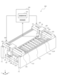
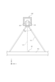
- FIG. 1 is a diagram showing an example of a laser processing machine 100 according to an embodiment of the present invention.
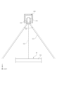
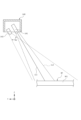
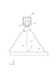
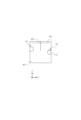
- FIG. 2 is a diagram showing an example of a line laser unit 140 shown in FIG. 1 .
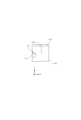
- FIG. 2 is a diagram showing an example of a line laser unit 140 shown in FIG. 1 .
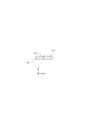
- 4 is a diagram showing an example of a workpiece W1 shown in an image captured by the imaging unit 142 shown in FIGS. 2 and 3.
- FIG. 11A to 11C are diagrams illustrating an example of image analysis processing by an image analysis unit 151.
- 11A to 11C are diagrams illustrating an example of image analysis processing by an image analysis unit 151.
- 11A to 11C are diagrams illustrating an example of image analysis processing by an image analysis unit 151.
- 11A to 11C are diagrams illustrating an example of image analysis processing by an image analysis unit 151.
- FIG. 2 is a diagram illustrating an example of the configuration of a line laser 141.
- FIG. 2 is a diagram illustrating an example of the configuration of a line laser 141.
- 13 is a diagram showing an example of a workpiece W1 shown in an image captured by the imaging unit 142 shown in FIG. 11 and FIG. 12.
- 11A to 11C are diagrams illustrating an example of image analysis processing by an image analysis unit 151.
- FIG. 18 is a diagram illustrating an example of a line laser unit 140 shown in FIG. 17.
- FIG. 18 is a diagram illustrating an example of a line laser unit 140 shown in FIG. 17.
- FIG. 18 is a diagram illustrating an example of a line laser unit 140 shown in FIG. 17.
- FIG. 11A to 11C are diagrams illustrating an example of image analysis processing by an image analysis unit 151.
- 2 is a diagram illustrating an example of the configuration of a line laser 141 and an imaging unit 142.
- FIG. FIG. 13 is a diagram showing an example of a laser processing machine 100 according to another embodiment.
- FIG. 13 is a diagram showing an example of a laser processing machine 100 according to another embodiment.
- FIG. 13 is a diagram showing an example of a laser processing machine 100 according to another embodiment.
- FIG. 13 is a diagram showing an example of a laser processing machine 100 according to another embodiment.
- FIG. 13 is a diagram showing an example of a laser processing machine 100 according to another embodiment.
- FIG. 32 is a diagram showing an example of a line laser unit 140 shown in FIG. 31 .
- FIG. 32 is a diagram showing an example of a line laser unit 140 shown in FIG. 31 .
- FIG. 32 is a diagram showing an example of a line laser unit 140 shown in FIG. 31 .
- FIG. 32 is a diagram showing an example of a line laser unit 140 shown in FIG. 31 .
- FIG. 11A to 11C are diagrams illustrating an example of image analysis processing by an image analysis unit 151.
- FIG. 13 is a diagram showing an example of a laser processing machine 100 according to another embodiment.
- the directions in the figures will be explained using the XYZ coordinate system.
- the vertical direction is the Z direction
- the horizontal directions are the X and Y directions.
- the side indicated by the arrows will be referred to as the + side, and the opposite side as the - side.
- FIG. 1 is a diagram showing an example of a laser processing machine 100 according to this embodiment.
- the laser processing machine 100 is a device that performs laser processing on a plate-shaped workpiece W1.
- the laser processing machine 100 includes a table 110, a laser head 120, a secondary processing tool 130, a line laser unit 140, and a control device 150.
- the plate-shaped workpiece W1 is an example of a workpiece.
- the table 110 is a member that supports the workpiece W1.
- the table 110 includes a base plate 111 and multiple support plates 112.
- the base plate 111 is a plate-shaped member.
- the support plates 112 are plate-shaped members that have multiple protrusions 112P at their upper ends.
- the support plates 112 are arranged side by side in the X direction, standing on the top surface of the base plate 111.
- the table 110 supports the workpiece W1 with the protrusions 112P.
- the laser head 120 is a device that irradiates the workpiece W1 supported on the table 110 with laser light to laser-machine the workpiece W1.
- the laser head 120 is provided on the first gantry 101.
- the laser head 120 shown in FIG. 1 is provided on the first gantry 101 via the first lifting section 103 and the first slider 102.
- the laser head 120 is capable of performing drilling to form a hole by irradiating the workpiece W1 with laser light along a predetermined closed path on the plate surface BF of the workpiece W1.
- the first gantry 101 is a device that is provided above the workpiece W1 supported by the table 110 and is movable in the X direction.
- the first gantry 101 shown in FIG. 1 is provided across the first frame F1 and the second frame F2 of the laser processing machine 100.
- the first gantry 101 shown in FIG. 1 moves in the X direction while being guided by the X guide G1 provided on the upper surfaces of the first frame F1 and the second frame F2.
- the first slider 102 is a device that is arranged above the workpiece W1 so as to be movable in the Y direction.
- the first slider 102 shown in FIG. 1 is arranged from the top surface of the first gantry 101 to the surface on the -X side.
- the first slider 102 shown in FIG. 1 moves in the Y direction while being guided by a Y guide G2 arranged on the top surface of the first gantry 101.
- the first lifting unit 103 is a device that is provided above the workpiece W1 and is movable in the Z direction.
- the first lifting unit 103 shown in FIG. 1 is provided on the side of the first slider 102.
- the first lifting unit 103 shown in FIG. 1 moves in the Z direction while being guided by a Z guide G3 provided on the side of the first slider 102.
- the laser head 120 shown in FIG. 1 is attached to the first lifting unit 103.
- the laser head 120 shown in FIG. 1 moves in the X direction above the workpiece W1 supported on the table 110 as the first gantry 101 moves in the X direction.
- the laser head 120 shown in FIG. 1 moves in the Y direction above the workpiece W1 supported on the table 110 as the first slider 102 moves in the Y direction.
- the laser head 120 shown in FIG. 1 moves in the Z direction above the workpiece W1 supported on the table 110 as the first lifting unit 103 moves in the Z direction.
- the secondary processing tool 130 is a tool that performs secondary processing on the laser-machined workpiece W1.
- the secondary processing tool 130 is provided on the second gantry 104.
- the secondary processing tool 130 shown in FIG. 1 is provided on the second gantry 104 via the second lifting section 106 and the second slider 105.
- the second gantry 104 is a device that is provided above the workpiece W1 supported by the table 110 and is movable in the X direction.
- the second gantry 104 shown in FIG. 1 is provided across the first frame F1 and the second frame F2 of the laser processing machine 100.
- the second gantry 104 shown in FIG. 1 moves in the X direction while being guided by the X guide G1.
- the second slider 105 is a device that is provided above the workpiece W1 and is movable in the Y direction.
- the second slider 105 shown in FIG. 1 is provided across from the top surface of the second gantry 104 to the -X side surface.
- the second slider 105 shown in FIG. 1 moves in the Y direction while being guided by a Y guide G2 provided on the top surface of the second gantry 104.
- the second lifting unit 106 is a device that is provided above the workpiece W1 and is movable in the Z direction.
- the second lifting unit 106 shown in FIG. 1 is provided on the side of the second slider 105.
- the second lifting unit 106 shown in FIG. 1 moves in the Z direction while being guided by a Z guide G3 provided on the side of the second slider 105.
- the secondary processing tool 130 shown in FIG. 1 is attached to the second lifting unit 106.
- the secondary processing tool 130 shown in FIG. 1 moves in the X direction above the workpiece W1 supported on the table 110 as the second gantry 104 moves in the X direction.
- the secondary processing tool 130 shown in FIG. 1 moves in the Y direction above the workpiece W1 supported on the table 110 as the second slider 105 moves in the Y direction.
- the secondary processing tool 130 shown in FIG. 1 moves in the Z direction above the workpiece W1 supported on the table 110 as the second lifting unit 106 moves in the Z direction.
- the line laser unit 140 is a device that projects linear laser light and captures an image of the projected linear laser light pattern.
- the line laser unit 140 is provided at any position above the workpiece W1.
- the line laser unit 140 shown in FIG. 1 is provided at a position on the support frame SF that allows the entire workpiece W1 to be captured.
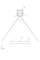
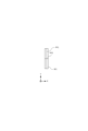
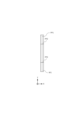
- FIGS. 2 and 3 are diagrams showing an example of the line laser unit 140 shown in FIG. 1.
- the line laser unit 140 includes a line laser 141 and an imaging unit 142.
- the line laser 141 is a device that projects linear laser light LL onto the plate surface BF of the workpiece W1 supported on the table 110.
- the line laser 141 shown in Figures 2 and 3 projects linear laser light LL extending in the X direction of the plate surface BF of the workpiece W1.
- the line laser 141 is driven by a drive unit (not shown) and is arranged so that its posture can be changed.
- the line laser 141 can project linear laser light LL to multiple projection positions by changing its posture and changing the direction of the optical axis.
- the imaging unit 142 is a device that images the plate surface BF of the workpiece W1 supported on the table 110.
- the imaging unit 142 captures the plate surface BF of the workpiece W1 by fitting the pattern of the linear laser light LL projected by the line laser 141 within the viewing angle AV.
- the line laser unit 140 shown in FIG. 1 is provided at a position on the support frame SF where the entire workpiece W1 can be imaged. Therefore, the imaging unit 142 shown in FIGS. 2 and 3 can capture the entire plate surface BF of the workpiece W1.
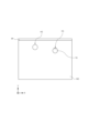
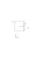
- FIG. 4 is a diagram showing an example of the workpiece W1 shown in an image captured by the imaging unit 142 shown in FIGS. 2 and 3.
- the workpiece W1 shown in FIG. 4 has a first hole H1 and a second hole H2 formed by drilling.
- the workpiece W1 shown in FIG. 4 has a projection pattern PP of the linear laser light LL projected by the line laser 141 shown in FIGS. 2 and 3 projected thereon.
- the second hole H2 has slag S1 remaining and is not pierced. Normally, the slug S1 cut out from the workpiece W1 by drilling falls from the workpiece W1 and is removed. However, if the position of the protrusion 112P and the position of the hole overlap, the slug S1 may be obstructed by the protrusion 112P and get stuck in the hole, preventing it from falling. Also, if a cutting failure occurs, the slug S1 may be welded to the workpiece W1 and not fall. The second hole H2 has no slug S1 remaining and is pierced.
- the line laser 141 shown in Figures 2 and 3 projects linear laser light LL extending in the X direction of the plate surface BF of the workpiece W1 to multiple projection positions in the Y direction of the plate surface BF of the workpiece W1.
- the Y direction in this embodiment is an example of the first direction.
- the X direction in this embodiment is an example of the second direction.
- control device 150 is a device that controls the laser processing machine 100.
- the control device 150 controls the first gantry 101, the first slider 102, the first lifting unit 103, and the laser head 120, thereby controlling the laser processing operation on the workpiece W1.
- the control device 150 controls the second gantry 104, the second slider 105, the second lifting unit 106, and the secondary processing tool 130, thereby controlling the secondary processing operation on the workpiece W1.
- the control device 150 functions as an image analysis unit 151.
- the image analysis unit 151 is a software module that analyzes the image captured by the imaging unit 142.
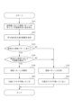
- FIG. 5 is a diagram showing an example of image analysis processing by the image analysis unit 151. After the linear laser light LL is projected and images are captured at all of the predetermined projection positions, the image analysis unit 151 executes the processing shown in FIG. 5.
- the image analysis unit 151 cuts out the area in each of the multiple images in which the projection pattern PP appears (S101).
- FIG. 6 is a diagram showing an example of the workpiece W1 shown in an image after cutout processing.
- the image analysis unit 151 determines that, for example, a high-luminance linear portion in the image extending in the X direction of the workpiece W1 is the projection pattern PP. Then, the image analysis unit 151 cuts out a specific range of area in the Y direction of the workpiece W1, for example, based on the area in which the projection pattern PP appears.
- the specific range of area cut out in one image is set so as not to overlap with the specific range of area cut out in another image.
- the image analysis unit 151 synthesizes the images after the cutout processing (S102).
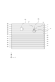
- FIG. 7 is a diagram showing an example of the workpiece W1 shown in the composite image.
- the image analysis unit 151 composites the images so that the processed images are connected in the Y direction of the workpiece W1, for example, in the order in which they were captured by the imaging unit 142.
- the image analysis unit 151 determines whether there is an interrupted projection pattern PP in the workpiece W1 that appears in the composite image (S103). In S103, the image analysis unit 151 determines that the projection pattern PP is interrupted if, for example, the linear portion determined to be the projection pattern PP is not continuous.
- the linear laser light LL when the linear laser light LL is projected so as to pass through a non-penetrating hole, the linear laser light LL is also projected onto the surface of the slag S1 remaining in the hole.
- the position of the linear laser light LL projected onto the surface of the slag S1 in the Y direction is different from the position of the linear laser light LL projected onto the plate surface BF of the workpiece W1. Therefore, the projection pattern PP projected so as to pass through a non-penetrating hole is likely to be a pattern in which an interrupted line is visible in the hole area in the image captured by the imaging unit 142.
- the image analysis unit 151 determines that the projection pattern PP in which an interrupted line is visible in the hole area is interrupted. For example, even if the hole is not penetrating like the first hole H1 shown in FIG. 7, the image analysis unit 151 determines that the projection pattern PP passing through the first hole H1 is interrupted.
- the linear laser light LL when the linear laser light LL is projected to pass through a through hole, the linear laser light LL is not projected in the hole area. Therefore, the projection pattern PP projected to pass through a through hole is likely to result in a pattern in which no lines are visible in the hole area in the image captured by the imaging unit 142.
- the image analysis unit 151 determines that the projection pattern PP in which no lines are visible in the hole area is interrupted. For example, when the hole is through like the second hole H2 shown in FIG. 7, the image analysis unit 151 determines that the projection pattern PP passing through the second hole H2 is interrupted.
- the image analysis unit 151 determines whether there is a discontinuous line at the interrupted location (S104).
- the projection pattern PP projected to pass through a non-penetrating hole is likely to become a pattern in which a broken line is seen in the hole area in the image captured by the imaging unit 142. For example, if there is a high-luminance linear pattern within a predetermined range in the direction corresponding to the Y direction of the workpiece W1 based on the position where the projection pattern PP is broken, the image analysis unit 151 determines that there is a discontinuous line at the break. For example, the projection pattern PP passing through the first hole H1 shown in FIG. 7 has a high-luminance linear pattern LP near the direction corresponding to the Y direction of the workpiece W1 based on the position where the projection pattern PP is broken.
- the image analysis unit 151 determines that there is a discontinuous line at the break. For example, if the hole is not all the way through, such as the first hole H1 shown in FIG. 7, the image analysis unit 151 determines that there is a discontinuous line at the break in the projection pattern PP that passes through the first hole H1.
- the projection pattern PP projected to pass through a through hole is likely to become a pattern in which no lines are visible in the hole area in the image captured by the imaging unit 142.
- the image analysis unit 151 determines that there is no discontinuous line at the interrupted point.
- the projection pattern PP passing through the second hole H2 shown in FIG. 7 does not have a high-luminance linear pattern LP in the vicinity in the direction corresponding to the Y direction of the workpiece W1, based on the position where the projection pattern PP is interrupted.
- the image analysis unit 151 determines that there is no discontinuous line at the interrupted point. For example, when a hole is through like the second hole H2 shown in FIG. 7, the image analysis unit 151 determines that there is no discontinuous line at the interrupted portion for the projection pattern PP that passes through the second hole H2.
- the image analysis unit 151 determines that the projection pattern PP is normal (S105) and ends the processing shown in FIG. 5.
- the image analysis unit 151 determines that the projection pattern PP is normal (S105) and ends the processing shown in FIG. 5.
- the image analysis unit 151 may indicate that the projection pattern PP is normal by having an output device (not shown) output the data.
- the output device is a device that receives data from the control device 150 and physically presents the data externally in a form that can be recognized by humans.
- the image analysis unit 151 determines that the projection pattern PP is abnormal (S106) and ends the process shown in FIG. 5.
- the image analysis unit 151 may indicate that the projection pattern PP is abnormal by having an output device (not shown) output the information.
- the laser processing machine 100 of this embodiment is a device that laser processes the workpiece W1.
- the laser processing machine 100 has a table 110 that has multiple protrusions 112P and supports the workpiece W1 by the protrusions 112P.
- the laser processing machine 100 has a laser head 120 that irradiates the workpiece W1 supported by the table 110 with laser light to laser process the workpiece W1.
- the laser processing machine 100 has a line laser 141 that projects linear laser light LL onto the plate surface BF of the workpiece W1 supported by the table 110.
- the laser processing machine 100 has an imaging unit 142 that images the plate surface BF of the workpiece W1 supported by the table 110.
- the line laser 141 projects linear laser light LL extending in the X direction of the plate surface BF of the workpiece W1 to multiple projection positions in the Y direction of the plate surface BF of the workpiece W1.
- the imaging unit 142 captures an image of the plate surface BF of the workpiece W1 by capturing the projection pattern PP of the linear laser light LL projected by the line laser 141 within the viewing angle AV.
- the laser processing machine 100 allows the user to determine whether there are any abnormalities in the workpiece W1 based on the projection pattern PP that appears in the image captured by the imaging unit 142.
- the laser processing machine 100 of this embodiment also includes an image analysis unit 151 that analyzes the image captured by the imaging unit 142.
- the image analysis unit 151 determines whether the projection pattern PP shown in the image is normal.
- the laser processing machine 100 allows the user to determine whether there are any abnormalities in the workpiece W1 based on the analysis results from the image analysis unit 151.
- the line laser 141 of this embodiment projects linear laser light LL at a first projection position in the Y direction and at a second projection position different from the first projection position.
- the imaging unit 142 images the plate surface BF of the workpiece W1 at the first projection position and the second projection position.
- the image analysis unit 151 analyzes an image obtained by combining the first image captured at the first projection position and the second image captured at the second projection position.
- the laser processing machine 100 allows the user to determine whether there are any abnormalities in the workpiece W1 shown in the composite image based on the analysis results by the image analysis unit 151.
- FIG. 8 is a diagram showing an example of image analysis processing by the image analysis unit 151. After the linear laser light LL is projected and images are captured at all of the predetermined projection positions, the image analysis unit 151 executes the processing shown in FIG. 8. The processing of S101 to S106 shown in FIG. 8 is the same as the processing of S101 to S106 shown in FIG. 5.
- the image analysis unit 151 determines that there is no abnormality in the laser-machined workpiece W1 (S201), and ends the process shown in FIG. 8.
- the image analysis unit 151 may indicate that there is no abnormality in the workpiece W1 by having an output device (not shown) output the result.
- the image analysis unit 151 does not need to indicate that the projection pattern PP is normal in S105.
- the image analysis unit 151 determines that there is an abnormality in the laser-machined workpiece W1 (S202), and ends the process shown in FIG. 8.
- the image analysis unit 151 may indicate that there is an abnormality in the workpiece W1 by outputting the abnormality to an output device (not shown).
- the image analysis unit 151 does not need to indicate that there is an abnormality in the projection pattern PP in S106.
- the image analysis unit 151 determines that there is no abnormality in the laser-machined workpiece W1 when the projection pattern PP shown in the image is normal.
- the laser processing machine 100 can allow the user to recognize whether there is any abnormality in the workpiece W1 based on the analysis results by the image analysis unit 151.
- FIG. 9 is a diagram showing an example of image analysis processing by the image analysis unit 151. After the linear laser light LL is projected and images are captured at all of the predetermined projection positions, the image analysis unit 151 executes the processing shown in FIG. 9. The processing of S101 to S106 shown in FIG. 9 is the same as the processing of S101 to S106 shown in FIG. 5.
- the image analysis unit 151 determines that the hole is through (S301) and ends the process shown in FIG. 9. In S301, the image analysis unit 151 may indicate that the hole is through by outputting the information to an output device (not shown). If the image analysis unit 151 indicates that the hole is through in S301, it is not necessary for the image analysis unit 151 to indicate that the projection pattern PP is normal in S105.
- the image analysis unit 151 determines that the hole does not penetrate through (S302), and ends the process shown in FIG. 9. In S302, the image analysis unit 151 may indicate that the hole does not penetrate through by outputting the information to an output device (not shown). If it indicates that the hole does not penetrate through in S302, the image analysis unit 151 does not need to indicate that the projection pattern PP is abnormal in S106.
- the laser head 120 of this embodiment is capable of performing drilling to form a hole by irradiating laser light along a predetermined closed path on the plate surface BF of the workpiece W1.
- the image analysis unit 151 in this example determines that the hole is through when the projection pattern PP shown in the image is normal.
- the laser processing machine 100 can allow the user to recognize whether the hole is pierced or not based on the analysis results from the image analysis unit 151.
- FIG. 10 is a diagram showing an example of image analysis processing by the image analysis unit 151. After the linear laser light LL is projected and images are captured at all of the predetermined projection positions, the image analysis unit 151 executes the processing shown in FIG. 10. The processing of S101 to S106 shown in FIG. 10 is the same as the processing of S101 to S106 shown in FIG. 5.
- the image analysis unit 151 determines that no slag S1 remains in the hole (S401), and ends the process shown in FIG. 10.
- the image analysis unit 151 may indicate that no slag S1 remains in the hole by having an output device (not shown) output that.
- the image analysis unit 151 does not need to indicate that the projection pattern PP is normal in S105.
- the image analysis unit 151 determines that slug S1 remains in the hole (S402), and ends the process shown in FIG. 10.
- the image analysis unit 151 may indicate that slug S1 remains in the hole by outputting to an output device (not shown).
- the image analysis unit 151 does not need to indicate that the projection pattern PP is abnormal in S106.
- the laser head 120 of this embodiment is capable of performing drilling to form a hole by irradiating laser light along a predetermined closed path on the plate surface BF of the workpiece W1.
- the image analysis unit 151 in this example determines that no slag S1 remains in the hole when the projection pattern PP shown in the image is normal.
- the laser processing machine 100 can allow the user to recognize whether or not any slag S1 remains in the hole based on the analysis results from the image analysis unit 151.
- FIGS. 11 and 12 are diagrams showing an example of the configuration of the line laser 141.
- the line laser 141 shown in FIG. 11 and FIG. 12 projects, as linear laser light LL, a first linear laser light LL1 extending in the X direction of the plate surface BF of the workpiece W1 and a second linear laser light LL2 extending in the Y direction.
- the line laser 141 is driven by a drive unit (not shown) and is arranged so that its posture can be changed.
- the line laser 141 can project the first linear laser light LL1 to multiple projection positions by changing its posture and changing the direction of the optical axis.
- FIG. 13 is a diagram showing an example of a workpiece W1 shown in an image captured by the imaging unit 142 shown in FIGS. 11 and 12.
- the workpiece W1 shown in FIG. 13 has a first hole H1 and a second hole H2 formed by drilling, similar to the workpiece W1 shown in FIG. 4.
- a first projection pattern PP1 of the first linear laser light LL1 and a second projection pattern PP2 of the second linear laser light LL2 by the line laser 141 shown in FIGS. 11 and 12 are projected onto the workpiece W1 shown in FIG. 13.
- the line laser 141 shown in Figures 11 and 12 projects a first linear laser light LL1 extending in the X direction of the plate surface BF of the workpiece W1 to multiple projection positions in the Y direction of the plate surface BF of the workpiece W1.
- the line laser 141 shown in Figures 11 and 12 also projects a second linear laser light LL2 extending in the Y direction of the plate surface BF of the workpiece W1.
- the Y direction in this embodiment is an example of the first direction.
- the X direction in this embodiment is an example of the second direction.
- FIG. 14 is a diagram showing an example of image analysis processing by the image analysis unit 151. After the linear laser light LL is projected and images are captured at all of the predetermined projection positions, the image analysis unit 151 executes the processing shown in FIG. 14. The processing of S103 to S106 shown in FIG. 14 is the same as the processing of S103 to S106 shown in FIG. 5.
- the image analysis unit 151 cuts out the areas in each of the multiple images in which the first projection pattern PP1 and the second projection pattern PP2 appear (S501).
- FIG. 15 is a diagram showing an example of the workpiece W1 shown in an image after cutout processing.
- the image analysis unit 151 determines that, for example, a high-luminance linear portion in the image extending in the X direction of the workpiece W1 is the first projection pattern PP1. Then, the image analysis unit 151 cuts out a specific range of area in the Y direction of the workpiece W1, for example, based on the area in which the first projection pattern PP1 appears.
- the specific range of area cut out in one image is set so as not to overlap with the specific range of area cut out in another image.
- the image analysis unit 151 synthesizes the image after cutout processing using the second projection pattern PP2 as a landmark (S502).
- FIG. 16 is a diagram showing an example of the workpiece W1 shown in the composite image.
- the image analysis unit 151 composites the images so that the processed images are connected in the Y direction of the workpiece W1, for example, in the order in which they were captured by the imaging unit 142.
- the image analysis unit 151 determines, for example, that a high-luminance linear portion extending in the Y direction of the workpiece W1 is the second projection pattern PP2.
- the image analysis unit 151 composites the first image and the second image so that, for example, the second projection pattern PP2 shown in the first image and the second projection pattern PP2 shown in the second image are connected in a straight line.
- the line laser 141 in this example emits the first linear laser light LL1 extending in the X direction and the second linear laser light LL2 extending in the Y direction.
- the image analysis unit 151 in this example combines the first image and the second image based on the projection pattern PP of the second linear laser light LL2 reflected in the image.
- the image analysis unit 151 can accurately combine the first image and the second image.
- FIG. 17 is a diagram showing an example of a laser processing machine 100 according to another embodiment.
- the laser processing machine 100 shown in FIG. 17 includes a table 110, a laser head 120, a secondary processing tool 130, a line laser unit 140, and a control device 150, similar to the laser processing machine 100 shown in FIG. 1.
- the line laser unit 140 shown in FIG. 17 is provided in the laser head 120.
- FIGS. 18 to 20 are diagrams showing an example of the line laser unit 140 shown in FIG. 17.
- the line laser unit 140 includes a line laser 141 and an imaging unit 142.
- the laser head 120 moves in the X direction above the workpiece W1 supported on the table 110 as the first gantry 101 moves in the X direction.
- the line laser 141 shown in FIGS. 18 to 20 can project linear laser light LL to multiple projection positions in the X direction on the plate surface BF of the workpiece W1 as the first gantry 101 moves.
- the line laser 141 shown in FIGS. 18 to 20 projects, as linear laser light LL, a first linear laser light LL1 extending in the Y direction on the plate surface BF of the workpiece W1 and a second linear laser light LL2 extending in the X direction.
- the X direction in this embodiment is an example of the first direction.
- the Y direction in this embodiment is an example of the second direction.
- the laser head 120 moves in the Y direction above the workpiece W1 supported on the table 110 as the first slider 102 moves in the Y direction.
- the line laser 141 can project the linear laser light LL at a first position and a second position in the Y direction of the projection position as the first slider 102 moves.
- the line laser 141 projects the first linear laser light LL1 onto the left half area of the workpiece W1 when viewing the workpiece W1 from the -X side at the first position in the Y direction.
- the line laser 141 projects the first linear laser light LL1 onto the right half area of the workpiece W1 when viewing the workpiece W1 from the -X side at the second position in the Y direction.
- the imaging unit 142 can capture images of the projection pattern PP at multiple projection positions by moving the first gantry 101. Also, the imaging unit 142 can capture images of the projection pattern PP at a first position and a second position in the Y direction of the projection position by moving the first slider 102 at the projection position.
- FIG. 21 is a diagram showing an example of a workpiece W1 shown in an image captured at a first position in the Y direction.
- the first projection pattern PP1 projected at the first position extends in the Y direction from the end of the workpiece W1 on the +Y side.
- the second projection pattern PP2 extends in the X direction.
- FIG. 22 is a diagram showing an example of a workpiece W1 shown in an image captured at a second position in the Y direction.
- the first projection pattern PP1 projected at the second position extends in the Y direction of the workpiece W1 from the -Y side end of the workpiece W1.
- the second projection pattern PP2 extends in the X direction.
- FIG. 23 is a diagram showing an example of image analysis processing by the image analysis unit 151. After the linear laser light LL is projected and images are captured at all of the predetermined projection positions, the image analysis unit 151 executes the processing shown in FIG. 23. The processing of S103 to S106 shown in FIG. 23 is the same as the processing of S103 to S106 shown in FIG. 5.
- the image analysis unit 151 cuts out the areas in each of the multiple images in which the first projection pattern PP1 and the second projection pattern PP2 appear (S601).
- FIG. 24 is a diagram showing an example of the workpiece W1 shown in an image after cutout processing.
- the image analysis unit 151 determines that, for example, a high-luminance linear portion in the image extending in the Y direction of the workpiece W1 is the first projection pattern PP1. Then, the image analysis unit 151 cuts out a specific range of area in the X direction of the workpiece W1, for example, based on the area in which the first projection pattern PP1 appears.
- the specific range of area cut out in one image is set so as not to overlap with the specific range of area cut out in another image.
- the image analysis unit 151 uses the first projection pattern PP1 as a landmark to combine the two images after cutout processing (S602).
- FIG. 25 is a diagram showing an example of the workpiece W1 that appears in an image obtained by combining two images after cutout processing.
- the image analysis unit 151 combines, for example, an image captured at a first position and an image captured at a second position at the same projection position in the X direction so that they are connected.
- the image analysis unit 151 determines, for example, that a high-luminance linear portion extending in the Y direction of the workpiece W1 is the first projection pattern PP1.
- the image analysis unit 151 combines the images so that, for example, the first projection pattern PP1 captured in one image and the first projection pattern PP1 captured in the other image are connected in a straight line.
- the image analysis unit 151 synthesizes all the images using the second projection pattern PP2 as a landmark (S603).
- FIG. 26 is a diagram showing an example of the workpiece W1 that appears in the combined image.
- the image analysis unit 151 combines the images so that the combined images are connected in the direction corresponding to the X direction of the workpiece W1, for example, in the order in which they were captured by the imaging unit 142.
- the image analysis unit 151 determines, for example, that a high-luminance linear portion extending in the direction corresponding to the X direction of the workpiece W1 is the second projection pattern PP2. Then, the image analysis unit 151 combines the images so that, for example, the second projection pattern PP2 in the first image and the second projection pattern PP2 in the second image are connected in a straight line.
- the laser processing machine 100 of this embodiment includes a first gantry 101 that is movably disposed above the workpiece W1.
- the laser head 120 is disposed on the first gantry 101.
- the line laser 141 and the imaging unit 142 are disposed on the laser head 120.
- the line laser 141 can project linear laser light LL at multiple projection positions as the first gantry 101 moves.
- the imaging unit 142 can image the projection pattern PP at multiple projection positions as the first gantry 101 moves.
- the laser processing machine 100 can align the line laser 141 and the imaging unit 142 to the projection position by utilizing the operation of the first gantry 101 on which the laser head 120 is provided.
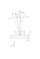
- FIG. 27 shows an example of the configuration of the line laser 141 and the imaging unit 142.
- the line laser 141 shown in FIG. 27 is driven by a drive unit, not shown, and is arranged so that its posture can be changed.
- the line laser 141 shown in FIG. 27 is driven by a drive unit, not shown, and can be moved to a first position where the angle of the optical axis with respect to the plate surface BF of the workpiece W1 is ⁇ 1.
- the line laser 141 shown in FIG. 27 is also driven by a drive unit, not shown, and can be moved to a second position where the angle of the optical axis with respect to the plate surface BF of the workpiece W1 is ⁇ 2, which is different from ⁇ 1.
- the imaging unit 142 shown in FIG. 27 is driven by a drive unit, not shown, and is arranged so that its posture can be changed.
- the imaging unit 142 shown in FIG. 27 is driven by a drive unit, not shown, and can be moved to a first position where the angle of the optical axis with respect to the plate surface BF of the workpiece W1 is ⁇ 3.
- the imaging unit 142 shown in FIG. 27 is also driven by a drive unit, not shown, and can be moved to a second position where the angle of the optical axis with respect to the plate surface BF of the workpiece W1 is ⁇ 2, which is different from ⁇ 1.
- the projection pattern PP shown in the image captured by the imaging unit 142 may appear normal due to the relationship between the angle of the optical axis of the line laser 141 and the angle of the optical axis of the imaging unit 142.
- the line laser 141 shown in FIG. 27 projects linear laser light LL at a first position and a second position.
- the imaging unit 142 images the projection pattern PP of the linear laser light LL projected from the first position and the projection pattern PP of the linear laser light LL projected from the second position.
- the imaging unit 142 may image the plate surface BF of the workpiece W1 at either the first position or the second position.
- the image analysis unit 151 analyzes an image of the projection pattern PP projected from the first position and an image of the projection pattern PP projected from the second position.
- the projection pattern PP shown in the image captured by the imaging unit 142 appears differently when the linear laser light LL is projected from the first position and when the linear laser light LL is projected from the second position.
- the imaging unit 142 shown in FIG. 27 images the plate surface BF of the workpiece W1 at the first position and the second position.
- the line laser 141 may project the linear laser light LL from either the first position or the second position.
- the image analysis unit 151 analyzes an image of the projection pattern PP projected from the first position and an image of the projection pattern PP projected from the second position.
- the projection pattern PP shown in the image captured by the imaging unit 142 appears differently when captured from the first position and when captured from the second position.
- the imaging unit 142 in this example images the plate surface BF of the workpiece W1 at a first position where the angle of the optical axis with respect to the plate surface BF of the workpiece W1 is a first angle, and at a second position where the angle is ⁇ 2, which is different from ⁇ 1.
- the laser processing machine 100 can increase the likelihood that the projection pattern PP will appear abnormally in the image if there is an abnormality in the workpiece W1.
- the line laser 141 in this example projects linear laser light LL at a first position where the angle of the optical axis with respect to the plate surface BF of the workpiece W1 is ⁇ 1, and at a second position where the angle is ⁇ 2, which is different from ⁇ 1.
- the laser processing machine 100 can increase the likelihood that the projection pattern PP will appear abnormally in the image if there is an abnormality in the workpiece W1.
- FIG. 28 is a diagram showing an example of a laser processing machine 100 according to another embodiment.
- the laser processing machine 100 shown in FIG. 28 includes a table 110, a laser head 120, a secondary processing tool 130, a line laser unit 140, and a control device 150, similar to the laser processing machine 100 shown in FIG. 1.
- the line laser unit 140 shown in FIG. 28 is provided on the secondary processing tool 130.
- the line laser unit 140 shown in FIG. 28 includes a line laser 141 and an imaging unit 142, similar to the line laser unit 140 shown in FIGS. 18 to 20.
- the secondary processing tool 130 moves in the X direction above the workpiece W1 supported on the table 110 as the second gantry 104 moves in the X direction.
- the line laser 141 can project linear laser light LL to multiple projection positions in the X direction on the plate surface BF of the workpiece W1.
- the line laser 141 projects, for example, a first linear laser light LL1 extending in the Y direction on the plate surface BF of the workpiece W1 and a second linear laser light LL2 extending in the X direction as linear laser light LL.
- the X direction in this embodiment is an example of the first direction.
- the Y direction in this embodiment is an example of the second direction.
- the secondary machining tool 130 moves in the Y direction above the workpiece W1 supported on the table 110 as the second slider 105 moves in the Y direction.
- the line laser 141 can project the linear laser light LL at a first position and a second position in the Y direction of the projection position as the second slider 105 moves.
- the line laser 141 projects the first linear laser light LL1 onto the left half area of the workpiece W1 when viewing the workpiece W1 from the -X side at the first position in the Y direction.
- the line laser 141 projects the first linear laser light LL1 onto the right half area of the workpiece W1 when viewing the workpiece W1 from the -X side at the second position in the Y direction.
- the imaging unit 142 can capture images of the first projection pattern PP1 and the second projection pattern PP2 at a plurality of projection positions by moving the second gantry 104. Also, the imaging unit 142 can capture images of the first projection pattern PP1 and the second projection pattern PP2 at a first position and a second position in the Y direction of the projection position by moving the second slider 105 at the projection position.
- the image analysis unit 151 executes processing similar to that shown in FIG. 23.
- the laser processing machine 100 of this embodiment includes the second gantry 104 that is movably provided above the workpiece W1.
- the laser processing machine 100 includes the secondary processing tool 130 that is provided on the second gantry 104 and performs secondary processing on the laser-processed workpiece W1.
- the line laser 141 and the imaging unit 142 are provided on the secondary processing tool 130.
- the line laser 141 can project linear laser light LL to multiple projection positions by moving the second gantry 104.
- the imaging unit 142 can image the projection pattern PP at multiple projection positions by moving the second gantry 104.
- the laser processing machine 100 can align the line laser 141 and the imaging unit 142 to the projection position by utilizing the operation of the second gantry 104 on which the secondary processing tool 130 is provided.
- FIG. 29 is a diagram showing an example of a laser processing machine 100 according to another embodiment.
- the laser processing machine 100 shown in FIG. 29 includes a table 110, a laser head 120, a secondary processing tool 130, a line laser unit 140, and a control device 150, similar to the laser processing machine 100 shown in FIG. 1.
- the laser processing machine 100 according to this embodiment includes a plurality of line laser units 140.
- the laser processing machine 100 shown in FIG. 29 includes a first line laser unit 140A and a second line laser unit 140B as the line laser units 140.
- the first line laser unit 140A and the second line laser unit 140B are provided on the first gantry 101.
- the first line laser unit 140A and the second line laser unit 140B are provided side by side in the Y direction.
- the first line laser unit 140A and the second line laser unit 140B are equipped with a line laser 141 and an imaging unit 142, similar to the line laser unit 140 shown in Figures 18 to 20.
- the line laser 141 can project linear laser light LL to multiple projection positions in the X direction on the plate surface BF of the workpiece W1.
- the line laser 141 projects, as the linear laser light LL, a first linear laser light LL1 extending in the Y direction on the plate surface BF of the workpiece W1 and a second linear laser light LL2 extending in the X direction.
- the X direction is an example of the first direction.
- the Y direction is an example of the second direction.
- the line laser 141 of the first line laser unit 140A is capable of projecting linear laser light LL at a first position in the Y direction of the projection position. As shown in FIG. 18, the line laser 141 of the first line laser unit 140A projects the first linear laser light LL1 onto the left half area of the workpiece W1 when viewing the workpiece W1 from the -X side at the first position in the Y direction.
- the line laser 141 of the first line laser unit 140A is an example of a first line laser.
- the line laser 141 of the second line laser unit 140B is capable of projecting linear laser light LL at a second position in the Y direction of the projection position. As shown in FIG. 19, the line laser 141 of the second line laser unit 140B projects the first linear laser light LL1 onto the right half area of the workpiece W1 when viewing the workpiece W1 from the -X side at the second position in the Y direction.
- the line laser 141 of the second line laser unit 140B is an example of a second line laser.
- the imaging unit 142 can capture images of the projection pattern PP at multiple projection positions by moving the first gantry 101.
- the imaging section 142 of the first line laser unit 140A fits the projection pattern PP projected by the line laser 141 of the first line laser unit 140A into the angle of view AV.
- the imaging section 142 of the first line laser unit 140A is an example of a first imaging section.
- the imaging section 142 of the second line laser unit 140B accommodates the projection pattern PP projected by the line laser 141 of the second line laser unit 140B within the angle of view AV.
- the imaging section 142 of the second line laser unit 140B is an example of a second imaging section.
- the image analysis unit 151 analyzes an image that is a composite of an image captured by the imaging unit 142 of the first line laser unit 140A and an image captured by the imaging unit 142 of the second line laser unit 140B.
- the image captured by the imaging section 142 of the first line laser unit 140A is an image of the first projection pattern PP1 extending from the end of the workpiece W1 on the +Y side to about the middle in the Y direction, similar to the example shown in FIG. 21.
- the image captured by the imaging section 142 of the first line laser unit 140A is an example of the first image.
- the image captured by the imaging section 142 of the second line laser unit 140B is an image that shows the first projection pattern PP1 extending from the middle of the workpiece W1 in the Y direction to the end on the -Y side, similar to the example shown in FIG. 22.
- the image captured by the imaging section 142 of the second line laser unit 140B is an example of the second image.
- the image analysis unit 151 executes processing similar to that shown in FIG. 23.
- the laser processing machine 100 of this embodiment includes the first gantry 101 that is movably disposed above the workpiece W1.
- the line laser 141 and the imaging unit 142 are provided on the first gantry 101.
- the line laser 141 can project linear laser light LL to multiple projection positions as the first gantry 101 moves.
- the imaging unit 142 can image the projection pattern PP at multiple projection positions as the first gantry 101 moves.
- the laser processing machine 100 can align the line laser 141 and the imaging unit 142 to the projection position by using the operation of the first gantry 101.
- the laser processing machine 100 also includes, as the line laser 141, a line laser 141 of the first line laser unit 140A and a line laser 141 of the second line laser unit 140B.
- the line laser 141 of the first line laser unit 140A and the line laser 141 of the second line laser unit 140B are arranged side by side in the Y direction.
- the laser processing machine 100 also includes, as the imaging section 142, an imaging section 142 of the first line laser unit 140A and an imaging section 142 of the second line laser unit 140B.
- the imaging section 142 of the first line laser unit 140A fits the projection pattern PP projected by the line laser 141 of the first line laser unit 140A within the angle of view AV.
- the imaging section 142 of the second line laser unit 140B fits the projection pattern PP projected by the line laser 141 of the second line laser unit 140B within the angle of view AV.
- the image analysis unit 151 analyzes an image that is a composite of an image captured by the imaging unit 142 of the first line laser unit 140A and an image captured by the imaging unit 142 of the second line laser unit 140B.
- the laser processing machine 100 allows the user to determine whether there are any abnormalities in a wide area in the Y direction based on the analysis results from the image analysis unit 151.
- FIG. 30 is a diagram showing an example of a laser processing machine 100 according to another embodiment.
- the laser processing machine 100 shown in FIG. 30 includes a table 110, a laser head 120, a secondary processing tool 130, a line laser unit 140, and a control device 150, similar to the laser processing machine 100 shown in FIG. 1.
- the laser processing machine 100 according to this embodiment includes a plurality of line laser units 140.
- the laser processing machine 100 shown in FIG. 30 includes a first line laser unit 140A and a second line laser unit 140B as the line laser units 140.
- the first line laser unit 140A and the second line laser unit 140B are provided on the second gantry 104.
- the first line laser unit 140A and the second line laser unit 140B are provided side by side in the Y direction.
- the first line laser unit 140A and the second line laser unit 140B are equipped with a line laser 141 and an imaging unit 142, similar to the line laser unit 140 shown in Figures 18 to 20.
- the line laser 141 can project linear laser light LL to multiple projection positions in the X direction on the plate surface BF of the workpiece W1.
- the line laser 141 projects, as the linear laser light LL, a first linear laser light LL1 extending in the Y direction on the plate surface BF of the workpiece W1 and a second linear laser light LL2 extending in the X direction.
- the X direction is an example of the first direction.
- the Y direction is an example of the second direction.
- the line laser 141 of the first line laser unit 140A is capable of projecting linear laser light LL at a first position in the Y direction of the projection position. As shown in FIG. 18, the line laser 141 of the first line laser unit 140A projects the first linear laser light LL1 onto the left half area of the workpiece W1 when viewing the workpiece W1 from the -X side at the first position in the Y direction.
- the line laser 141 of the first line laser unit 140A is an example of a first line laser.
- the line laser 141 of the second line laser unit 140B is capable of projecting linear laser light LL at a second position in the Y direction of the projection position. As shown in FIG. 19, the line laser 141 of the second line laser unit 140B projects the first linear laser light LL1 onto the right half area of the workpiece W1 when viewing the workpiece W1 from the -X side at the second position in the Y direction.
- the line laser 141 of the second line laser unit 140B is an example of a second line laser.
- the imaging unit 142 can capture images of the projection pattern PP at multiple projection positions by moving the second gantry 104.
- the imaging section 142 of the first line laser unit 140A fits the projection pattern PP projected by the line laser 141 of the first line laser unit 140A into the angle of view AV.
- the imaging section 142 of the first line laser unit 140A is an example of a first imaging section.
- the imaging section 142 of the second line laser unit 140B accommodates the projection pattern PP projected by the line laser 141 of the second line laser unit 140B within the angle of view AV.
- the imaging section 142 of the second line laser unit 140B is an example of a second imaging section.
- the image analysis unit 151 analyzes an image that is a composite of an image captured by the imaging unit 142 of the first line laser unit 140A and an image captured by the imaging unit 142 of the second line laser unit 140B.
- the image captured by the imaging section 142 of the first line laser unit 140A is an image of the first projection pattern PP1 extending from the end of the workpiece W1 on the +Y side to about the middle in the Y direction, similar to the example shown in FIG. 21.
- the image captured by the imaging section 142 of the first line laser unit 140A is an example of the first image.
- the image captured by the imaging section 142 of the second line laser unit 140B is an image that shows the first projection pattern PP1 extending from the middle of the workpiece W1 in the Y direction to the end on the -Y side, similar to the example shown in FIG. 22.
- the image captured by the imaging section 142 of the second line laser unit 140B is an example of the second image.
- the image analysis unit 151 executes processing similar to that shown in FIG. 23.
- the laser processing machine 100 of this embodiment includes the second gantry 104 that is movably disposed above the workpiece W1.
- the line laser 141 and the imaging unit 142 are provided on the second gantry 104.
- the line laser 141 can project linear laser light LL to multiple projection positions as the second gantry 104 moves.
- the imaging unit 142 can image the projection pattern PP at multiple projection positions as the second gantry 104 moves.
- the laser processing machine 100 can align the line laser 141 and the imaging unit 142 to the projection position by using the operation of the second gantry 104.
- FIG. 31 is a diagram showing an example of a laser processing machine 100 according to another embodiment.
- the laser processing machine 100 shown in FIG. 31 includes a table 110, a laser head 120, a secondary processing tool 130, a line laser unit 140, and a control device 150, similar to the laser processing machine 100 shown in FIG. 1.
- the laser processing machine 100 shown in FIG. 31 also includes a transport device 160.
- the transport device 160 is a device that transports the laser-machined workpiece W1.
- the transport device 160 has multiple gripping parts 161 that grip the workpiece W1.
- the transport device 160 is provided so that it can enter the position of the workpiece W1 supported on the table 110 through an opening A1 provided in the second frame F2 and the third frame F3.
- the transport device 160 grips the workpiece W1 supported on the table 110 with the gripping parts 161, it transports the workpiece W1 in the Y direction.
- the secondary processing tool 130 shown in FIG. 31 is provided on the transport path of the workpiece W1 by the transport device 160.
- the secondary processing tool 130 shown in FIG. 31 moves in the X direction while being guided by a tool guide G4 provided on the third frame F3.
- the secondary processing tool 130 shown in FIG. 31 performs secondary processing on the workpiece W1 transported by the transport device 160.
- the line laser unit 140 shown in Figure 31 is provided on the secondary processing tool 130.
- FIGS. 32 to 35 are diagrams showing an example of the line laser unit 140 shown in FIG. 31.
- the line laser unit 140 includes a line laser 141 and an imaging unit 142.
- the line laser 141 shown in Figures 32 to 35 is capable of projecting linear laser light LL to multiple projection positions in the Y direction on the plate surface BF of the workpiece W1 as the workpiece W1 is transported in the Y direction.
- the line laser 141 shown in Figures 32 to 35 projects, as linear laser light LL, a first linear laser light LL1 extending in the X direction on the plate surface BF of the workpiece W1 and a second linear laser light LL2 extending in the Y direction.
- the Y direction in this embodiment is an example of the first direction.
- the X direction in this embodiment is an example of the second direction.
- the line laser 141 can project the linear laser light LL at a first position, a second position, and a third position in the X direction of the projection position by moving the secondary processing tool 130.
- the line laser 141 projects the first linear laser light LL1 onto the left area of the workpiece W1 when viewing the workpiece W1 from the -Y side at the first position in the X direction.
- the line laser 141 projects the first linear laser light LL1 onto the central area of the workpiece W1 when viewing the workpiece W1 from the -Y side at the second position in the X direction.
- the line laser 141 projects the first linear laser light LL1 onto the right area of the workpiece W1 when viewing the workpiece W1 from the -Y side at the third position in the X direction.
- the imaging unit 142 can capture images of the projection pattern PP at multiple projection positions as the workpiece W1 is transported in the Y direction.
- the imaging unit 142 can capture images of the projection pattern PP at a first position, a second position, and a third position in the X direction of the projection position as the secondary processing tool 130 moves at the projection position.
- FIG. 36 is a diagram showing an example of a workpiece W1 shown in an image captured at a first position in the X direction.
- the first projection pattern PP1 projected at the first position extends in the X direction from the -X side end of the workpiece W1.
- the second projection pattern PP2 extends in the Y direction.
- FIG. 37 shows an example of a workpiece W1 captured in an image taken at a second position in the X direction.
- the first projection pattern PP1 projected at the second position extends in the X direction in the middle of the workpiece W1.
- the second projection pattern PP2 extends in the Y direction.
- FIG. 38 is a diagram showing an example of a workpiece W1 shown in an image captured at a third position in the X direction.
- the first projection pattern PP1 projected at the third position extends in the X direction from the end of the workpiece W1 on the +X side.
- the second projection pattern PP2 extends in the Y direction.
- FIG. 39 is a diagram showing an example of image analysis processing by the image analysis unit 151. After the linear laser light LL is projected and images are captured at all of the predetermined projection positions, the image analysis unit 151 executes the processing shown in FIG. 39. The processing of S103 to S106 shown in FIG. 39 is the same as the processing of S103 to S106 shown in FIG. 5.
- the image analysis unit 151 cuts out the areas in each of the multiple images in which the first projection pattern PP1 and the second projection pattern PP2 appear (S701).
- FIG. 40 is a diagram showing an example of the workpiece W1 shown in an image after cutout processing.
- the image analysis unit 151 determines that, for example, a high-luminance linear portion in the image extending in the X direction of the workpiece W1 is the first projection pattern PP1. Then, the image analysis unit 151 cuts out a specific range of area in the X direction of the workpiece W1, for example, based on the area in which the first projection pattern PP1 appears.
- the specific range of area cut out in one image is set so as not to overlap with the specific range of area cut out in another image.
- the image analysis unit 151 uses the first projection pattern PP1 as a landmark to combine the three images after cutout processing (S702).
- FIG. 41 is a diagram showing an example of the workpiece W1 that appears in an image obtained by combining three images after cutout processing.
- the image analysis unit 151 combines, for example, an image captured at a first position, an image captured at a second position, and an image captured at a third position at the same projection position in the Y direction so that they are connected.
- the image analysis unit 151 determines, for example, that a high-luminance linear portion extending in the direction corresponding to the X direction of the workpiece W1 is the first projection pattern PP1. Then, the image analysis unit 151 combines the images so that, for example, the first projection pattern PP1 captured in one image and the first projection pattern PP1 captured in the other image are connected in a straight line.
- the image analysis unit 151 synthesizes all the images using the second projection pattern PP2 as a landmark (S703).
- FIG. 42 is a diagram showing an example of the workpiece W1 that appears in the combined image.
- the image analysis unit 151 combines the images so that the combined images are connected in the Y direction of the workpiece W1, for example, in the order in which they were captured by the imaging unit 142.
- the image analysis unit 151 determines, for example, that a high-luminance linear portion extending in the Y direction of the workpiece W1 is the second projection pattern PP2. Then, the image analysis unit 151 combines the images so that the second projection pattern PP2 in the first image and the second projection pattern PP2 in the second image are connected in a straight line.
- the laser processing machine 100 of this embodiment includes a transport device 160 that transports the laser-processed workpiece W1 in the Y direction.
- the laser processing machine 100 includes a secondary processing tool 130 that performs secondary processing on the workpiece W1 transported by the transport device 160.
- the line laser 141 and the imaging unit 142 are provided on the secondary processing tool 130.
- the line laser 141 can project linear laser light LL to multiple projection positions.
- the imaging unit 142 can image the projection pattern PP at multiple projection positions.
- the laser processing machine 100 can align the line laser 141 and the imaging unit 142 to the projection position by using the operation of transporting the workpiece W1 by the transport device 160.
- FIG. 43 is a diagram showing an example of a laser processing machine 100 according to another embodiment.
- the laser processing machine 100 shown in FIG. 43 includes a table 110, a laser head 120, a secondary processing tool 130, a line laser unit 140, and a control device 150, similar to the laser processing machine 100 shown in FIG. 31.
- the laser processing machine 100 according to this embodiment includes a plurality of line laser units 140.
- the laser processing machine 100 shown in FIG. 43 includes a first line laser unit 140A, a second line laser unit 140B, and a third line laser unit 140C as the line laser units 140.
- the first line laser unit 140A to the third line laser unit 140C are provided on the transport path of the workpiece W1 by the transport device 160.
- the first line laser unit 140A to the third line laser unit 140C shown in FIG. 43 are provided in a position in the third frame F3 facing the workpiece W1 transported by the transport device 160.
- the first line laser unit 140A, the second line laser unit 140B, and the third line laser unit 140C are provided side by side in the X direction.
- the first line laser unit 140A to the third line laser unit 140C each include a line laser 141 and an imaging unit 142, similar to the line laser unit 140 shown in Figures 32 to 35.
- the line laser 141 is capable of projecting linear laser light LL to multiple projection positions in the Y direction on the plate surface BF of the workpiece W1 as the workpiece W1 is transported in the Y direction.
- the line laser 141 projects, as the linear laser light LL, a first linear laser light LL1 extending in the X direction on the plate surface BF of the workpiece W1 and a second linear laser light LL2 extending in the Y direction.
- the Y direction in this embodiment is an example of the first direction.
- the X direction in this embodiment is an example of the second direction.
- the line laser 141 of the first line laser unit 140A can project linear laser light LL at a first position in the X direction of the projection position. As shown in FIG. 32, the line laser 141 of the first line laser unit 140A projects the first linear laser light LL1 onto the left area of the workpiece W1 when viewing the workpiece W1 from the -Y side at the first position in the X direction.
- the line laser 141 of the second line laser unit 140B can project linear laser light LL at a second position in the X direction of the projection position. As shown in FIG. 33, the line laser 141 of the second line laser unit 140B projects the first linear laser light LL1 onto the central area of the workpiece W1 when viewing the workpiece W1 from the -Y side at the second position in the X direction.
- the line laser 141 of the third line laser unit 140C can project linear laser light LL at a third position in the X direction of the projection position. As shown in FIG. 34, the line laser 141 of the third line laser unit 140C projects a first linear laser light LL1 onto the right area of the workpiece W1 when viewing the workpiece W1 from the -Y side at a first position in the X direction.
- the imaging unit 142 can capture images of the projection pattern PP at multiple projection positions as the workpiece W1 is transported in the Y direction.
- the imaging section 142 of the first line laser unit 140A fits the projection pattern PP projected by the line laser 141 of the first line laser unit 140A within the angle of view AV.
- the imaging section 142 of the second line laser unit 140B fits the projection pattern PP projected by the line laser 141 of the second line laser unit 140B within the angle of view AV.
- the imaging section 142 of the third line laser unit 140C fits the projection pattern PP projected by the line laser 141 of the third line laser unit 140C within the angle of view AV.
- the image analysis unit 151 analyzes an image that is a composite of the images captured by the imaging units 142 of the first line laser unit 140A to the third line laser unit 140C.
- the image captured by the imaging section 142 of the first line laser unit 140A is an image of the first projection pattern PP1 extending in the X direction from the -X side end of the workpiece W1, similar to the example shown in FIG. 36.
- the image captured by the imaging section 142 of the second line laser unit 140B is an image of the first projection pattern PP1 extending in the X direction at the middle of the workpiece W1 in the X direction, similar to the example shown in FIG. 37.
- the image captured by the imaging section 142 of the third line laser unit 140C is an image of the first projection pattern PP1 extending in the X direction from the end of the workpiece W1 on the +X side, similar to the example shown in FIG. 38.
- the laser processing machine 100 of this embodiment is equipped with a transport device 160 that transports the laser-processed workpiece W1 in the Y direction.
- the laser processing machine 100 is equipped with a secondary processing tool 130 that performs secondary processing on the workpiece W1 transported by the transport device 160.
- the line laser 141 and the imaging unit 142 are provided on the transport path of the transport device 160.
- the line laser 141 is capable of projecting linear laser light LL to multiple projection positions as the workpiece W1 is transported by the transport device 160.
- the imaging unit 142 is capable of imaging the projection pattern PP at multiple projection positions as the workpiece W1 is transported by the transport device 160.
- the laser processing machine 100 can align the line laser 141 and the imaging unit 142 to the projection position by using the operation of transporting the workpiece W1 by the transport device 160.
- the image analysis unit 151 may determine that there are no chips on the surface of the laser-machined workpiece W1 when the projection pattern PP shown in the image is normal. According to this example, the laser processing machine 100 can allow the user to recognize whether there are any chips on the surface of the workpiece W1 based on the analysis results by the image analysis unit 151.
- the CPU (not shown) of the control device 150 does not need to function as the image analysis unit 151.
- the laser processing machine 100 may be equipped with a computer different from the control device 150.
- the CPU of the computer only needs to function as the image analysis unit 151.
- the image analysis unit 151 can execute the image analysis process shown in Figs. 8 to 10 even when the laser processing machine 100 is equipped with the line laser 141 shown in Figs. 11 and 12. In that case, the image analysis unit 151 executes the processes of S501 and S502 shown in Fig. 14 instead of the processes of S101 and S102 in the image analysis process shown in Figs. 8 to 10.
- the laser processing machine 100 shown in Figures 17, 28 to 31, and 43 can use a line laser 141 that projects only one linear laser beam LL.
- the laser processing machine 100 shown in Figures 28 to 31 and 43 can be equipped with an imaging unit 142 that captures images at a first position where the angle of the optical axis relative to the plate surface BF is a first angle, and at a second position where the angle is a second angle.
- the laser processing machine 100 shown in Figures 28 to 31 and 43 can use a line laser 141 that projects linear laser light LL at a first position where the angle of the optical axis relative to the plate surface BF is a first angle, and at a second position where the angle is a second angle.
- the laser processing machine 100 of the above embodiment laser processes a plate-shaped workpiece W1.
- the workpiece W1 laser processed by the laser processing machine 100 is not limited to being plate-shaped.
- the laser processing machine 100 is capable of laser processing, for example, a square pipe, a round pipe, or other workpiece W1.
- the laser head 120 may irradiate the surface of the workpiece W1 supported by the table 110 with laser light to laser process the workpiece W1.
- the line laser 141 may project linear laser light onto the surface of the workpiece W1 supported by the table 110.
- the imaging unit 142 may image the surface of the workpiece W1 indicated by the table 110.
- Laser processing machine 101 First gantry 102 First slider 103 First lifting section 104 Second gantry 105 Second slider 106 Second lifting section 110 Table 111 Base plate 112 Support plate 112P Protrusion 120 Laser head 130 Secondary processing tool 140 Line laser unit 140A First line laser unit 140B Second line laser unit 140C Third line laser unit 141 Line laser 142 Imaging section 150 Control device 160 Transport device 161 Grip section A1 Opening AV Field angle BF Plate surface F1 First frame F2 Second frame F3 Third frame G1 X guide G2 Y guide G3 Z guide G4 Tool guide H1 First hole H2 Second hole LL Linear laser light LL1 First linear laser light LL2 Second linear laser light LP Linear pattern PP Projection pattern PP1 First projection pattern PP2 Second projection pattern S1 Slug SF Support frame W1 Workpiece
Landscapes
- Engineering & Computer Science (AREA)
- Physics & Mathematics (AREA)
- Optics & Photonics (AREA)
- Plasma & Fusion (AREA)
- Mechanical Engineering (AREA)
- Laser Beam Processing (AREA)
Abstract
【課題】スラグが落下していないワークは、二次加工において、二次加工工具を破損させる要因となり得る。 【解決手段】本発明の一態様は、ワークをレーザ加工するレーザ加工機である。レーザ加工機は、複数の突起部を有し、突起部によりワークを支持するテーブルを備える。レーザ加工機は、テーブルに支持されたワークにレーザ光を照射してワークをレーザ加工するレーザヘッドを備える。レーザ加工機は、テーブルに支持されたワークに線状レーザ光を投影するラインレーザを備える。レーザ加工機は、テーブルに支持されたワークを撮像する撮像部を備える。ラインレーザは、ワークの第1方向における複数の投影位置に対して、ワークの第1方向に直交する第2方向に延びる線状レーザ光を投影する。撮像部は、ラインレーザにより投影された線状レーザ光の投影パターンを撮像する。
Description
本発明は、レーザ加工機に関する。
特許文献1に記載されているように、レーザ加工機は、複数の突起を持つテーブルでワークを支持し、その上に配置されたレーザヘッドがテーブル上のワークにレーザ光を照射して加工する。
特許文献1のレーザ加工機は、レーザで加工されたワークを二次加工するための工具を備えている。このレーザ加工機は、例えば、二次加工のための下穴として、所定の経路に沿ってレーザ光を照射してワークに穴を作る穴あけ加工を行うことがある。通常、穴あけ加工によってワークから切り抜かれた不要な部分は、ワークから落下して取り除かれる。
突起部の位置と穴部の位置とが重なっている場合、穴あけ加工によってワークから切り抜かれた不要な部分は、突起部により阻害されて穴部に嵌まり込み落下しないことがある。また、切断不良が生じた場合、ワークから切り抜かれた不要な部分は、ワークに溶着して落下しないことがある。ワークから切り抜かれた不要な部分が落下していないワークは、二次加工において、二次加工工具を破損させる要因となり得る。
また、レーザ加工により生じた切りくずがワークに残っている場合、切りくずは、二次加工において打痕の要因となり得る。
本発明の一態様は、ワークをレーザ加工するレーザ加工機である。レーザ加工機は、複数の突起部を有し、突起部によりワークを支持するテーブルを備える。レーザ加工機は、テーブルに支持されたワークにレーザ光を照射してワークをレーザ加工するレーザヘッドを備える。レーザ加工機は、テーブルに支持されたワークに線状レーザ光を投影するラインレーザを備える。レーザ加工機は、テーブルに支持されたワークを撮像する撮像部を備える。ラインレーザは、ワークの第1方向における複数の投影位置に対して、ワークの第1方向に直交する第2方向に延びる線状レーザ光を投影する。撮像部は、ラインレーザにより投影された線状レーザ光の投影パターンを撮像する。
本発明の一態様によれば、レーザ加工機は、撮像部により撮像された画像に写る投影パターンにより、ワークに異常がないかをユーザに判断させることができる。
レーザ加工機は、ワークの上方において移動可能に設けられたガントリを備えてよい。ラインレーザ及び撮像部は、ガントリに設けられてよい。ラインレーザは、ガントリが移動することにより、複数の投影位置に対して線状レーザ光を投影可能であってよい。撮像部は、ガントリが移動することにより、複数の投影位置における投影パターンを撮像可能であってよい。この態様によれば、レーザ加工機は、ガントリの動作を利用して、ラインレーザと撮像部とを投影位置に位置合わせできる。
レーザ加工機は、ワークの上方において移動可能に設けられたガントリを備えてよい。レーザヘッドは、ガントリに設けられてよい。ラインレーザ及び撮像部は、レーザヘッドに設けられてよい。ラインレーザは、ガントリが移動することにより、複数の投影位置に対して線状レーザ光を投影可能であってよい。撮像部は、ガントリが移動することにより、複数の投影位置における投影パターンを撮像可能であってよい。この態様によれば、レーザ加工機は、レーザヘッドが設けられたガントリの動作を利用して、ラインレーザと撮像部とを投影位置に位置合わせできる。
レーザ加工機は、ワークの上方において移動可能に設けられたガントリを備えてよい。レーザ加工機は、ガントリに設けられ、レーザ加工されたワークを二次加工する二次加工工具を備えてよい。ラインレーザ及び撮像部は、二次加工工具に設けられてよい。ラインレーザは、ガントリが移動することにより、複数の投影位置に対して線状レーザ光を投影可能であってよい。撮像部は、ガントリが移動することにより、複数の投影位置における投影パターンを撮像可能であってよい。この態様によれば、レーザ加工機は、二次加工工具が設けられたガントリの動作を利用して、ラインレーザと撮像部とを投影位置に位置合わせできる。
レーザ加工機は、レーザ加工されたワークを第1方向に向けて搬送する搬送装置を備えてよい。レーザ加工機は、搬送装置により搬送されたワークを二次加工する二次加工工具を備えてよい。ラインレーザ及び撮像部は、搬送装置による搬送経路に設けられてよい。ラインレーザは、搬送装置によりワークが搬送されることにより、複数の投影位置に対して線状レーザ光を投影可能であってよい。撮像部は、搬送装置によりワークが搬送されることにより、複数の投影位置における投影パターンを撮像可能であってよい。この態様によれば、レーザ加工機は、搬送装置によりワークを搬送する動作を利用して、ラインレーザと撮像部とを投影位置に位置合わせできる。
レーザ加工機は、レーザ加工されたワークを第1方向に向けて搬送する搬送装置を備えてよい。レーザ加工機は、搬送装置により搬送されたワークを二次加工する二次加工工具を備えてよい。ラインレーザ及び撮像部は、二次加工工具に設けられてよい。ラインレーザは、搬送装置によりワークが搬送されることにより、複数の投影位置に対して線状レーザ光を投影可能であってよい。撮像部は、搬送装置によりワークが搬送されることにより、複数の投影位置における投影パターンを撮像可能であってよい。この態様によれば、レーザ加工機は、搬送装置によりワークを搬送する動作を利用して、ラインレーザと撮像部とを投影位置に位置合わせできる。
撮像部は、ワークに対する光軸の角度が第1角度となる位置と、第1角度とは異なる第2角度となる位置とにおいてワークを撮像してよい。この態様によれば、レーザ加工機は、ワークに異常がある場合に、投影パターンが異常な状態で画像に写る可能性を高めることができる。
ラインレーザは、ワークに対する光軸の角度が第1角度となる第1位置と、第1角度とは異なる第2角度となる第2位置とにおいて線状レーザ光を投影してよい。この態様によれば、レーザ加工機は、ワークに異常がある場合に、投影パターンが異常な状態で画像に写る可能性を高めることができる。
レーザ加工機は、撮像部により撮像された画像を解析する画像解析部を備えてよい。画像解析部は、画像に写る投影パターンが正常であるかを判定してよい。この態様によれば、レーザ加工機は、画像解析部による解析結果により、ワークに異常がないかをユーザに判断させることができる。
画像解析部は、画像に写る投影パターンが正常であるときに、レーザ加工されたワークに異常がないと判定してよい。この態様によれば、レーザ加工機は、画像解析部による解析結果により、ワークに異常がないかをユーザに認識させることができる。
レーザヘッドは、所定の閉経路に沿ってレーザ光を照射してワークに穴部を形成する穴あけ加工を行うことが可能であってよい。画像解析部は、画像に写る投影パターンが正常であるときに、穴部が貫通していると判定してよい。この態様によれば、レーザ加工機は、画像解析部による解析結果により、穴部が貫通しているかをユーザに認識させることができる。
レーザヘッドは、所定の閉経路に沿ってレーザ光を照射してワークに穴部を形成する穴あけ加工を行うことが可能であってよい。画像解析部は、画像に写る投影パターンが正常であるときに、穴部にスラグが残っていないと判定してよい。この態様によれば、レーザ加工機は、画像解析部による解析結果により、穴部にスラグが残っていないかをユーザに認識させることができる。
画像解析部は、画像に写る投影パターンが正常であるときに、レーザ加工されたワークの表面に切りくずがないと判定してよい。この態様によれば、レーザ加工機は、画像解析部による解析結果により、ワークの表面に切りくずがないかをユーザに認識させることができる。
ラインレーザは、第1方向における第1投影位置と、第1投影位置とは異なる第2投影位置とにおいて、線状レーザ光を投影してよい。撮像部は、第1投影位置と第2投影位置とにおいて、ワークを撮像してよい。画像解析部は、第1投影位置において撮像された第1画像と、第2投影位置において撮像された第2画像とを合成した画像を解析してよい。この態様によれば、レーザ加工機は、画像解析部による解析結果により、合成された画像に写るワークに異常がないかをユーザに判断させることができる。
ラインレーザは、線状レーザ光として、第1方向に延びる第1線状レーザ光と、第2方向に延びる第2線状レーザ光とを投影してよい。画像解析部は、画像に写る第1線状レーザ光の投影パターンを基準にして、第1画像と第2画像とを合成してよい。この態様によれば、画像解析部は、第1画像と第2画像とを正確に合成できる。
レーザ加工機は、ラインレーザとして、第1ラインレーザと、第2方向において第1ラインレーザに並んで設けられた第2ラインレーザとを備えてよい。レーザ加工機は、撮像部として、第1ラインレーザにより投影された投影パターンを画角に収める第1撮像部と、第2ラインレーザにより投影された投影パターンを画角に収める第2撮像部と、を備えてよい。画像解析部は、第1撮像部により撮像された第1画像と、第2撮像部により撮像された第2画像とを合成した画像を解析してよい。この態様によれば、レーザ加工機は、画像解析部による解析結果により、第2方向における広い領域において異常がないかをユーザに判断させることができる。
以下、発明の実施形態を通じて本発明を説明するが、以下の実施形態は、特許請求の範囲に係る発明を限定するものではない。また、実施形態の中で説明されている特徴の組み合わせの全てが発明の解決手段に必須であるとは限らない。
以下、図中の方向は、XYZ座標系を用いて説明する。このXYZ座標系は、鉛直方向をZ方向とし、水平方向をX方向、Y方向とする。また、X方向、Y方向及びZ方向は、適宜、矢印によって指し示す側を+側と称し、その反対側を-側と称する。
図1は、本実施形態に係るレーザ加工機100の一例を示す図である。レーザ加工機100は、板状のワークW1をレーザ加工する装置である。レーザ加工機100は、テーブル110、レーザヘッド120、二次加工工具130、ラインレーザユニット140及び制御装置150を備える。板状のワークW1は、ワークの一例である。
テーブル110は、ワークW1を支持する部材である。テーブル110は、ベースプレート111、及び複数の支持プレート112を備える。ベースプレート111は、板状の部材である。支持プレート112は、上端部に複数の突起部112Pを有する板状の部材である。支持プレート112は、ベースプレート111の上面に立った状態で、X方向に並んで設けられる。テーブル110は、突起部112PによりワークW1を支持する。
レーザヘッド120は、テーブル110に支持されたワークW1にレーザ光を照射してワークW1をレーザ加工する装置である。レーザヘッド120は、第1ガントリ101に設けられる。図1に示すレーザヘッド120は、第1昇降部103及び第1スライダ102を介して第1ガントリ101に設けられている。レーザヘッド120は、ワークW1の板面BFにおける所定の閉経路に沿ってレーザ光を照射して穴部を形成する穴あけ加工を行うことが可能である。
第1ガントリ101は、テーブル110に支持されたワークW1の上方においてX方向に移動可能に設けられる装置である。図1に示す第1ガントリ101は、レーザ加工機100の第1フレームF1から第2フレームF2にわたって設けられている。図1に示す第1ガントリ101は、第1フレームF1及び第2フレームF2の上面に設けられたXガイドG1に案内されてX方向に移動する。
第1スライダ102は、ワークW1の上方においてY方向に移動可能に設けられる装置である。図1に示す第1スライダ102は、第1ガントリ101の上面から-X側の面にわたって設けられている。図1に示す第1スライダ102は、第1ガントリ101の上面に設けられたYガイドG2に案内されてY方向に移動する。
第1昇降部103は、ワークW1の上方においてZ方向に移動可能に設けられる装置である。図1に示す第1昇降部103は、第1スライダ102の側面に設けられている。図1に示す第1昇降部103は、第1スライダ102の側面に設けられたZガイドG3に案内されてZ方向に移動する。
図1に示すレーザヘッド120は、第1昇降部103に取り付けられている。図1に示すレーザヘッド120は、第1ガントリ101がX方向に移動することにより、テーブル110に支持されたワークW1の上方においてX方向に移動する。図1に示すレーザヘッド120は、第1スライダ102がY方向に移動することにより、テーブル110に支持されたワークW1の上方においてY方向に移動する。図1に示すレーザヘッド120は、第1昇降部103がZ方向に移動することにより、テーブル110に支持されたワークW1の上方においてZ方向に移動する。
二次加工工具130は、レーザ加工されたワークW1を二次加工する工具である。二次加工工具130は、第2ガントリ104に設けられる。図1に示す二次加工工具130は、第2昇降部106及び第2スライダ105を介して第2ガントリ104に設けられている。
第2ガントリ104は、テーブル110に支持されたワークW1の上方においてX方向に移動可能に設けられる装置である。図1に示す第2ガントリ104は、レーザ加工機100の第1フレームF1から第2フレームF2にわたって設けられている。図1に示す第2ガントリ104は、XガイドG1に案内されてX方向に移動する。
第2スライダ105は、ワークW1の上方においてY方向に移動可能に設けられる装置である。図1に示す第2スライダ105は、第2ガントリ104の上面から-X側の面にわたって設けられている。図1に示す第2スライダ105は、第2ガントリ104の上面に設けられたYガイドG2に案内されてY方向に移動する。
第2昇降部106は、ワークW1の上方においてZ方向に移動可能に設けられる装置である。図1に示す第2昇降部106は、第2スライダ105の側面に設けられている。図1に示す第2昇降部106は、第2スライダ105の側面に設けられたZガイドG3に案内されてZ方向に移動する。
図1に示す二次加工工具130は、第2昇降部106に取り付けられている。図1に示す二次加工工具130は、第2ガントリ104がX方向に移動することにより、テーブル110に支持されたワークW1の上方においてX方向に移動する。図1に示す二次加工工具130は、第2スライダ105がY方向に移動することにより、テーブル110に支持されたワークW1の上方においてY方向に移動する。図1に示す二次加工工具130は、第2昇降部106がZ方向に移動することにより、テーブル110に支持されたワークW1の上方においてZ方向に移動する。
ラインレーザユニット140は、線状のレーザ光を投影すると共に、投影された線状のレーザ光のパターンを撮像する装置である。ラインレーザユニット140は、ワークW1の上方における任意の位置に設けられる。図1に示すラインレーザユニット140は、支持フレームSFにおける、ワークW1の全体を撮像可能な位置に設けられている。
図2及び図3は、図1に示すラインレーザユニット140の一例を示す図である。ラインレーザユニット140は、ラインレーザ141及び撮像部142を備える。
ラインレーザ141は、テーブル110に支持されたワークW1の板面BFに線状レーザ光LLを投影する装置である。図2及び図3に示すラインレーザ141は、ワークW1の板面BFのX方向に延びる線状レーザ光LLを投影する。ラインレーザ141は、図示しない駆動部により駆動され、姿勢が変化するように設けられる。ラインレーザ141は、姿勢が変化して光軸の向きが変化することにより、複数の投影位置に対して線状レーザ光LLを投影可能である。
撮像部142は、テーブル110に支持されたワークW1の板面BFを撮像する装置である。撮像部142は、ラインレーザ141により投影された線状レーザ光LLのパターンを画角AVに収めてワークW1の板面BFを撮像する。前述のとおり、図1に示すラインレーザユニット140は、支持フレームSFにおける、ワークW1の全体を撮像可能な位置に設けられている。したがって、図2及び図3に示す撮像部142は、ワークW1の板面BFの全体を撮像可能である。
図4は、図2及び図3に示す撮像部142により撮像された画像に写るワークW1の一例を示す図である。図4に示すワークW1は、穴あけ加工により第1穴部H1及び第2穴部H2が形成されている。図4に示すワークW1は、図2及び図3に示すラインレーザ141による線状レーザ光LLの投影パターンPPが投影されている。
第2穴部H2は、スラグS1が残っており、貫通していない。通常、穴あけ加工によりワークW1から切り抜かれたスラグS1は、ワークW1から落下して除去される。しかし、突起部112Pの位置と穴部の位置とが重なっている場合、スラグS1は、突起部112Pにより阻害されて穴部に嵌まり込み落下しないことがある。また、切断不良が生じた場合、スラグS1は、ワークW1に溶着して落下しないことがある。第2穴部H2は、スラグS1が残っておらず、貫通している。
図2及び図3に示すラインレーザ141は、ワークW1の板面BFのY方向における複数の投影位置に対して、ワークW1の板面BFのX方向に延びる線状レーザ光LLを投影する。本実施形態におけるY方向は、第1方向の一例である。本実施形態におけるX方向は、第2方向の一例である。
図1の説明に戻り、制御装置150は、レーザ加工機100を制御する装置である。制御装置150は、第1ガントリ101、第1スライダ102、第1昇降部103及びレーザヘッド120を制御することにより、ワークW1に対するレーザ加工の動作を制御する。制御装置150は、第2ガントリ104、第2スライダ105、第2昇降部106及び二次加工工具130を制御することにより、ワークW1に対する二次加工の動作を制御する。
制御装置150の図示しないCPU(Central Processing Unit)は、画像解析部151として機能する。画像解析部151は、撮像部142により撮像された画像を解析するソフトウェアモジュールである。
図5は、画像解析部151による画像解析処理の一例を示す図である。画像解析部151は、予め定められた全ての投影位置において、線状レーザ光LLが投影され、画像が撮像された後に、図5に示す処理を実行する。
まず、画像解析部151は、複数の各画像において、投影パターンPPが写る領域を切り抜き加工する(S101)。
図6は、切り抜き加工後の画像に写るワークW1の一例を示す図である。S101において、画像解析部151は、例えば、画像において、ワークW1のX方向にあたる方向に延びる高輝度の線状の部分が投影パターンPPであると判定する。そして、画像解析部151は、例えば、投影パターンPPが写る領域を基準にして、ワークW1のY方向にあたる方向において特定範囲の領域を切り抜き加工する。一の画像において切り抜き加工される特定範囲の領域は、例えば、他の画像において切り抜き加工される特定範囲の領域とは重複しないように設定される。
次に、画像解析部151は、切り抜き加工後の画像を合成する(S102)。
図7は、合成後の画像に写るワークW1の一例を示す図である。S102において、画像解析部151は、例えば、撮像部142により撮像された順に、ワークW1のY方向にあたる方向に加工後の画像が繋がるように合成する。
次に、画像解析部151は、合成後の画像に写るワークW1において、途切れた投影パターンPPがあるか判定する(S103)。S103において、画像解析部151は、例えば、投影パターンPPであると判定された線状の部分が連続していなければ、投影パターンPPが途切れていると判定する。
ここで、貫通していない穴部を通るように線状レーザ光LLが投影された場合、線状レーザ光LLは、穴部に残っているスラグS1の表面にも投影される。スラグS1の表面に投影される線状レーザ光LLの位置は、Y方向において、ワークW1の板面BFに投影される線状レーザ光LLの位置とは異なる。したがって、貫通していない穴部を通るように投影された投影パターンPPは、撮像部142により撮像された画像において、穴部の領域に途切れた線が見えるパターンとなる可能性が高い。穴部の領域に途切れた線が見える投影パターンPPについて、画像解析部151は、途切れていると判定する。例えば、図7に示す第1穴部H1のように穴部が貫通していなくても、画像解析部151は、第1穴部H1を通る投影パターンPPについて、途切れていると判定する。
一方、貫通している穴部を通るように線状レーザ光LLが投影された場合、線状レーザ光LLは、穴部の領域において投影されない。したがって、貫通している穴部を通るように投影された投影パターンPPは、撮像部142により撮像された画像において、穴部の領域に線が見えないパターンとなる可能性が高い。穴部の領域に線が見えない投影パターンPPについて、画像解析部151は、途切れていると判定する。例えば、図7に示す第2穴部H2のように穴部が貫通している場合、画像解析部151は、第2穴部H2を通る投影パターンPPについて、途切れていると判定する。
S103において途切れた投影パターンPPがある場合(S103;NO)、画像解析部151は、途切れた箇所において不連続な線があるか判定する(S104)。
前述のとおり、貫通していない穴部を通るように投影された投影パターンPPは、撮像部142により撮像された画像において、穴部の領域に途切れた線が見えるパターンとなる可能性が高い。画像解析部151は、例えば、投影パターンPPが途切れた位置を基準にして、ワークW1のY方向にあたる方向の所定範囲内に高輝度の線状のパターンがあれば、途切れた箇所において不連続な線があると判定する。例えば、図7示す第1穴部H1を通る投影パターンPPは、投影パターンPPが途切れた位置を基準にして、ワークW1のY方向にあたる方向の近傍に高輝度の線状パターンLPがある。穴部の領域に途切れた高輝度の線状パターンLPが見える投影パターンPPについて、画像解析部151は、途切れた箇所において不連続な線があると判定する。例えば、図7に示す第1穴部H1のように穴部が貫通していない場合、画像解析部151は、第1穴部H1を通る投影パターンPPについて、途切れた箇所において不連続な線があると判定する。
一方、前述のとおり、貫通している穴部を通るように投影された投影パターンPPは、撮像部142により撮像された画像において、穴部の領域に線が見えないパターンとなる可能性が高い。画像解析部151は、例えば、投影パターンPPが途切れた位置を基準にして、ワークW1のY方向にあたる方向の所定範囲内に高輝度の線状のパターンがなければ、途切れた箇所において不連続な線がないと判定する。例えば、図7示す第2穴部H2を通る投影パターンPPは、投影パターンPPが途切れた位置を基準にして、ワークW1のY方向にあたる方向の近傍に高輝度の線状パターンLPがない。穴部の領域に途切れた高輝度の線状パターンLPが見えない投影パターンPPについて、画像解析部151は、途切れた箇所において不連続な線がないと判定する。例えば、図7に示す第2穴部H2のように穴部が貫通している場合、画像解析部151は、第2穴部H2を通る投影パターンPPについて、途切れた箇所において不連続な線がないと判定する。
S103において途切れた投影パターンPPがない場合(S103;NO)画像解析部151は、投影パターンPPが正常であると判定し(S105)、図5に示す処理を終了する。
投影パターンPPが途切れていても、S104において不連続な線がない場合(S104;NO)、画像解析部151は、投影パターンPPが正常であると判定し(S105)、図5に示す処理を終了する。
S105において、画像解析部151は、投影パターンPPが正常であることを、図示しない出力装置に出力させることにより提示してよい。出力装置は、制御装置150からデータを受け取って、人間に認識できる形で外部に物理的に提示する装置である。
S104において不連続な線がある場合(S104;YES)、画像解析部151は、投影パターンPPが異常であると判定し(S106)、図5に示す処理を終了する。S106において、画像解析部151は、投影パターンPPが異常であることを、図示しない出力装置に出力させることにより提示してよい。
以上、本実施形態のレーザ加工機100は、ワークW1をレーザ加工する装置である。レーザ加工機100は、複数の突起部112Pを有し、突起部112PによりワークW1を支持するテーブル110を備える。レーザ加工機100は、テーブル110に支持されたワークW1にレーザ光を照射してワークW1をレーザ加工するレーザヘッド120を備える。レーザ加工機100は、テーブル110に支持されたワークW1の板面BFに線状レーザ光LLを投影するラインレーザ141を備える。レーザ加工機100は、テーブル110に支持されたワークW1の板面BFを撮像する撮像部142を備える。ラインレーザ141は、ワークW1の板面BFのY方向における複数の投影位置に対して、ワークW1の板面BFのX方向に延びる線状レーザ光LLを投影する。撮像部142は、ラインレーザ141により投影された線状レーザ光LLの投影パターンPPを画角AVに収めてワークW1の板面BFを撮像する。
本実施形態によれば、レーザ加工機100は、撮像部142により撮像された画像に写る投影パターンPPにより、ワークW1に異常がないかをユーザに判断させることができる。
また、本実施形態のレーザ加工機100は、撮像部142により撮像された画像を解析する画像解析部151を備える。画像解析部151は、画像に写る投影パターンPPが正常であるかを判定する。
本実施形態によれば、レーザ加工機100は、画像解析部151による解析結果により、ワークW1に異常がないかをユーザに判断させることができる。
また、本実施形態のラインレーザ141は、Y方向における第1投影位置と、第1投影位置とは異なる第2投影位置とにおいて、線状レーザ光LLを投影する。撮像部142は、第1投影位置と第2投影位置とにおいて、ワークW1の板面BFを撮像する。画像解析部151は、第1投影位置において撮像された第1画像と、第2投影位置において撮像された第2画像とを合成した画像を解析する。
本実施形態によれば、レーザ加工機100は、画像解析部151による解析結果により、合成された画像に写るワークW1に異常がないかをユーザに判断させることができる。
図8は、画像解析部151による画像解析処理の一例を示す図である。画像解析部151は、予め定められた全ての投影位置において、線状レーザ光LLが投影され、画像が撮像された後に、図8に示す処理を実行する。図8に示すS101~S106の処理は、図5に示すS101~S106の処理と同様の処理である。
S105の処理を実行した後、画像解析部151は、レーザ加工されたワークW1に異常がないと判定し(S201)、図8に示す処理を終了する。S201において、画像解析部151は、ワークW1に異常がないことを、図示しない出力装置に出力させることにより提示してよい。S201においてワークW1に異常がないことを提示する場合、画像解析部151は、S105において、投影パターンPPが正常であることを提示しなくてよい。
S106の処理を実行した後、画像解析部151は、レーザ加工されたワークW1に異常があると判定し(S202)、図8に示す処理を終了する。S202において、画像解析部151は、ワークW1に異常があることを、図示しない出力装置に出力させることにより提示してよい。S202においてワークW1に異常があることを提示する場合、画像解析部151は、S106において、投影パターンPPが異常であることを提示しなくてよい。
以上、この例の画像解析部151は、画像に写る投影パターンPPが正常であるときに、レーザ加工されたワークW1に異常がないと判定する。
この例の形態によれば、レーザ加工機100は、画像解析部151による解析結果により、ワークW1に異常がないかをユーザに認識させることができる。
図9は、画像解析部151による画像解析処理の一例を示す図である。画像解析部151は、予め定められた全ての投影位置において、線状レーザ光LLが投影され、画像が撮像された後に、図9に示す処理を実行する。図9に示すS101~S106の処理は、図5に示すS101~S106の処理と同様の処理である。
S105の処理を実行した後、画像解析部151は、穴部が貫通していると判定し(S301)、図9に示す処理を終了する。S301において、画像解析部151は、穴部が貫通していることを、図示しない出力装置に出力させることにより提示してよい。S301において穴部が貫通していることを提示する場合、画像解析部151は、S105において、投影パターンPPが正常であることを提示しなくてよい。
S106の処理を実行した後、画像解析部151は、穴部が貫通していないと判定し(S302)、図9に示す処理を終了する。S302において、画像解析部151は、穴部が貫通していないことを、図示しない出力装置に出力させることにより提示してよい。S302において穴部が貫通していないことを提示する場合、画像解析部151は、S106において、投影パターンPPが異常であることを提示しなくてよい。
以上、本実施形態のレーザヘッド120は、ワークW1の板面BFにおける所定の閉経路に沿ってレーザ光を照射して穴部を形成する穴あけ加工を行うことが可能である。この例の画像解析部151は、画像に写る投影パターンPPが正常であるときに、穴部が貫通していると判定する。
この例の形態によれば、レーザ加工機100は、画像解析部151による解析結果により、穴部が貫通しているかをユーザに認識させることができる。
図10は、画像解析部151による画像解析処理の一例を示す図である。画像解析部151は、予め定められた全ての投影位置において、線状レーザ光LLが投影され、画像が撮像された後に、図10に示す処理を実行する。図10に示すS101~S106の処理は、図5に示すS101~S106の処理と同様の処理である。
S105の処理を実行した後、画像解析部151は、穴部にスラグS1が残っていないと判定し(S401)、図10に示す処理を終了する。S401において、画像解析部151は、穴部にスラグS1が残っていないことを、図示しない出力装置に出力させることにより提示してよい。S401において穴部にスラグS1が残っていないことを提示する場合、画像解析部151は、S105において、投影パターンPPが正常であることを提示しなくてよい。
S106の処理を実行した後、画像解析部151は、穴部にスラグS1が残っていると判定し(S402)、図10に示す処理を終了する。S402において、画像解析部151は、穴部にスラグS1が残っていることを、図示しない出力装置に出力させることにより提示してよい。S402において穴部にスラグS1が残っていることを提示する場合、画像解析部151は、S106において、投影パターンPPが異常であることを提示しなくてよい。
以上、本実施形態のレーザヘッド120は、ワークW1の板面BFにおける所定の閉経路に沿ってレーザ光を照射して穴部を形成する穴あけ加工を行うことが可能である。この例の画像解析部151は、画像に写る投影パターンPPが正常であるときに、穴部にスラグS1が残っていないと判定する。
この例の形態によれば、レーザ加工機100は、画像解析部151による解析結果により、穴部にスラグS1が残っていないかをユーザに認識させることができる。
図11及び図12は、ラインレーザ141の構成の一例を示す図である。図11及び図12に示すラインレーザ141は、線状レーザ光LLとして、ワークW1の板面BFのX方向に延びる第1線状レーザ光LL1と、Y方向に延びる第2線状レーザ光LL2とを投影する。ラインレーザ141は、図示しない駆動部により駆動され、姿勢が変化するように設けられる。ラインレーザ141は、姿勢が変化して光軸の向きが変化することにより、複数の投影位置に対して第1線状レーザ光LL1を投影可能である。
図13は、図11及び図12に示す撮像部142により撮像された画像に写るワークW1の一例を示す図である。図13に示すワークW1は、図4に示すワークW1と同様に、穴あけ加工により第1穴部H1及び第2穴部H2が形成されている。図13に示すワークW1は、図11及び図12に示すラインレーザ141による第1線状レーザ光LL1の第1投影パターンPP1と、第2線状レーザ光LL2の第2投影パターンPP2とが投影されている。
図11及び図12に示すラインレーザ141は、ワークW1の板面BFのY方向における複数の投影位置に対して、ワークW1の板面BFのX方向に延びる第1線状レーザ光LL1を投影する。また、図11及び図12に示すラインレーザ141は、ワークW1の板面BFのY方向に延びる第2線状レーザ光LL2を投影する。本実施形態におけるY方向は、第1方向の一例である。本実施形態におけるX方向は、第2方向の一例である。
図14は、画像解析部151による画像解析処理の一例を示す図である。画像解析部151は、予め定められた全ての投影位置において、線状レーザ光LLが投影され、画像が撮像された後に、図14に示す処理を実行する。図14に示すS103~S106の処理は、図5に示すS103~S106の処理と同様の処理である。
まず、画像解析部151は、複数の各画像において、第1投影パターンPP1及び第2投影パターンPP2が写る領域を切り抜き加工する(S501)。
図15は、切り抜き加工後の画像に写るワークW1の一例を示す図である。S501において、画像解析部151は、例えば、画像において、ワークW1のX方向にあたる方向に延びる高輝度の線状の部分が第1投影パターンPP1であると判定する。そして、画像解析部151は、例えば、第1投影パターンPP1が写る領域を基準にして、ワークW1のY方向にあたる方向において特定範囲の領域を切り抜き加工する。一の画像において切り抜き加工される特定範囲の領域は、例えば、他の画像において切り抜き加工される特定範囲の領域とは重複しないように設定される。
次に、画像解析部151は、第2投影パターンPP2を目印にして、切り抜き加工後の画像を合成する(S502)。
図16は、合成後の画像に写るワークW1の一例を示す図である。S502において、画像解析部151は、例えば、撮像部142により撮像された順に、ワークW1のY方向にあたる方向に加工後の画像が繋がるように合成する。加工後の画像を合成するにあたり、画像解析部151は、例えば、ワークW1のY方向にあたる方向に延びる高輝度の線状の部分が第2投影パターンPP2であると判定する。そして、画像解析部151は、例えば、第1画像に写る第2投影パターンPP2と、第2画像に写る第2投影パターンPP2とが直線的に繋がるように、第1画像と第2画像とを合成する。
以上、この例のラインレーザ141は、X方向に延びる第1線状レーザ光LL1と、Y方向に延びる第2線状レーザ光LL2とを照射する。この例の画像解析部151は、画像に写る第2線状レーザ光LL2の投影パターンPPを基準にして、第1画像と第2画像とを合成する。
この例の形態によれば、画像解析部151は、第1画像と第2画像とを正確に合成できる。
図17は、他の実施形態に係るレーザ加工機100の一例を示す図である。図17に示すレーザ加工機100は、図1に示すレーザ加工機100と同様に、テーブル110、レーザヘッド120、二次加工工具130、ラインレーザユニット140及び制御装置150を備える。図17に示すラインレーザユニット140は、レーザヘッド120に設けられている。
図18から図20は、図17に示すラインレーザユニット140の一例を示す図である。ラインレーザユニット140は、ラインレーザ141及び撮像部142を備える。
上述のとおり、レーザヘッド120は、第1ガントリ101がX方向に移動することにより、テーブル110に支持されたワークW1の上方においてX方向に移動する。図18から図20に示すラインレーザ141は、第1ガントリ101が移動することにより、ワークW1の板面BFのX方向における複数の投影位置に対して、線状レーザ光LLを投影可能である。図18から図20に示すラインレーザ141は、線状レーザ光LLとして、ワークW1の板面BFのY方向に延びる第1線状レーザ光LL1と、X方向に延びる第2線状レーザ光LL2とを投影する。本実施形態におけるX方向は、第1方向の一例である。本実施形態におけるY方向は、第2方向の一例である。
また、上述のとおり、レーザヘッド120は、第1スライダ102がY方向に移動することにより、テーブル110に支持されたワークW1の上方においてY方向に移動する。ラインレーザ141は、第1スライダ102が移動することにより、投影位置のY方向における第1位置と第2位置とにおいて線状レーザ光LLを投影可能である。ラインレーザ141は、図18に示すように、Y方向における第1位置において、-X側からワークW1を見て、ワークW1の左半分の領域に第1線状レーザ光LL1を投影する。また、ラインレーザ141は、図19に示すように、Y方向における第2位置において、-X側からワークW1を見て、ワークW1の右半分の領域に第1線状レーザ光LL1を投影する。
撮像部142は、第1ガントリ101が移動することにより、複数の投影位置において、投影パターンPPを撮像可能である。また、撮像部142は、投影位置において第1スライダ102が移動することにより、投影位置のY方向における第1位置と第2位置とにおいて、投影パターンPPを撮像可能である。
図21は、Y方向における第1位置において撮像された画像に写るワークW1の一例を示す図である。第1位置において投影された第1投影パターンPP1は、ワークW1の+Y側の端部からY方向に延びている。第2投影パターンPP2は、X方向に延びている。
図22は、Y方向における第2位置において撮像された画像に写るワークW1の一例を示す図である。第2位置において投影された第1投影パターンPP1は、ワークW1の-Y側の端部からワークW1のY方向に延びている。第2投影パターンPP2は、X方向に延びている。
図23は、画像解析部151による画像解析処理の一例を示す図である。画像解析部151は、予め定められた全ての投影位置において、線状レーザ光LLが投影され、画像が撮像された後に、図23に示す処理を実行する。図23に示すS103~S106の処理は、図5に示すS103~S106の処理と同様の処理である。
まず、画像解析部151は、複数の各画像において、第1投影パターンPP1及び第2投影パターンPP2が写る領域を切り抜き加工する(S601)。
図24は、切り抜き加工後の画像に写るワークW1の一例を示す図である。S601において、画像解析部151は、例えば、画像において、ワークW1のY方向にあたる方向に延びる高輝度の線状の部分が第1投影パターンPP1であると判定する。そして、画像解析部151は、例えば、第1投影パターンPP1が写る領域を基準にして、ワークW1のX方向にあたる方向において特定範囲の領域を切り抜き加工する。一の画像において切り抜き加工される特定範囲の領域は、例えば、他の画像において切り抜き加工される特定範囲の領域とは重複しないように設定される。
次に、画像解析部151は、第1投影パターンPP1を目印にして、切り抜き加工後の2つの画像を合成する(S602)。
図25は、切り抜き加工後の2つの画像を合成した画像に写るワークW1の一例を示す図である。S602において、画像解析部151は、例えば、X方向における同じ投影位置における第1位置にて撮像された画像と、第2位置にて撮像された画像とが繋がるように合成する。2つの画像を合成するにあたり、画像解析部151は、例えば、ワークW1のY方向にあたる方向に延びる高輝度の線状の部分が第1投影パターンPP1であると判定する。そして、画像解析部151は、例えば、一方の画像に写る第1投影パターンPP1と、他方の画像に写る第1投影パターンPP1とが直線的に繋がるように画像を合成する。
次に、画像解析部151は、第2投影パターンPP2を目印にして、全ての画像を合成する(S603)。
図26は、合成後の画像に写るワークW1の一例を示す図である。S603において、画像解析部151は、例えば、撮像部142により撮像された順に、ワークW1のX方向にあたる方向に合成後の画像が繋がるように合成する。画像を合成するにあたり、画像解析部151は、例えば、ワークW1のX方向にあたる方向に延びる高輝度の線状の部分が第2投影パターンPP2であると判定する。そして、画像解析部151は、例えば、第1画像に写る第2投影パターンPP2と、第2画像に写る第2投影パターンPP2とが直線的に繋がるように合成する。
以上、本実施形態のレーザ加工機100は、ワークW1の上方において移動可能に設けられた第1ガントリ101を備える。レーザヘッド120は、第1ガントリ101に設けられる。ラインレーザ141及び撮像部142は、レーザヘッド120に設けられる。ラインレーザ141は、第1ガントリ101が移動することにより、複数の投影位置において線状レーザ光LLを投影可能である。撮像部142は、第1ガントリ101が移動することにより、複数の投影位置における投影パターンPPを撮像可能である。
本実施形態によれば、レーザ加工機100は、レーザヘッド120が設けられた第1ガントリ101の動作を利用して、ラインレーザ141と撮像部142とを投影位置に位置合わせできる。
図27は、ラインレーザ141及び撮像部142の構成の一例を示す図である。
図27に示すラインレーザ141は、図示しない駆動部により駆動され、姿勢が変化するように設けられる。図27に示すラインレーザ141は、図示しない駆動部により駆動され、ワークW1の板面BFに対する光軸の角度がθ1となる第1位置に移動可能である。また、図27に示すラインレーザ141は、図示しない駆動部により駆動され、ワークW1の板面BFに対する光軸の角度がθ1とは異なるθ2となる第2位置に移動可能である。
図27に示す撮像部142は、図示しない駆動部により駆動され、姿勢が変化するように設けられる。図27に示す撮像部142は、図示しない駆動部により駆動され、ワークW1の板面BFに対する光軸の角度がθ3となる第1位置に移動可能である。また、図27に示す撮像部142は、図示しない駆動部により駆動され、ワークW1の板面BFに対する光軸の角度がθ1とは異なるθ2となる第2位置に移動可能である。
穴部にスラグS1が残っている場合であっても、撮像部142により撮像された画像に写る投影パターンPPは、ラインレーザ141の光軸の角度と、撮像部142の光軸の角度との関係により、正常に見えることがある。
そこで、図27に示すラインレーザ141は、第1位置及び第2位置において、線状レーザ光LLを投影する。撮像部142は、第1位置から投影された線状レーザ光LLの投影パターンPPと、第2位置から投影された線状レーザ光LLの投影パターンPPとを撮像する。ラインレーザ141が第1位置及び第2位置において線状レーザ光LLを投影する場合、撮像部142は、第1位置と第2位置とのいずれか一方の位置において、ワークW1の板面BFを撮像してよい。画像解析部151は、第1位置から投影された投影パターンPPが撮像された画像と、第2位置から投影された投影パターンPPが撮像された画像とを解析する。撮像部142により撮像された画像に写る投影パターンPPは、第1位置から線状レーザ光LLが投影されたときと、第2位置から線状レーザ光LLが投影されたときとで、写り方が異なる。
もしくは、図27に示す撮像部142は、第1位置及び第2位置において、ワークW1の板面BFを撮像する。撮像部142が第1位置及び第2位置においてワークW1の板面BFを撮像する場合、ラインレーザ141は、第1位置と第2位置とのいずれか一方の位置から線状レーザ光LLを投影してよい。画像解析部151は、第1位置から投影された投影パターンPPが撮像された画像と、第2位置から投影された投影パターンPPが撮像された画像とを解析する。撮像部142により撮像された画像に写る投影パターンPPは、第1位置から撮像されたときと、第2位置から撮像されたときとで、写り方が異なる。
以上、この例の撮像部142は、ワークW1の板面BFに対する光軸の角度が第1角度となる第1位置と、θ1とは異なるθ2となる第2位置とにおいてワークW1の板面BFを撮像する。
この例の形態によれば、レーザ加工機100は、ワークW1に異常がある場合に、投影パターンPPが異常な状態で画像に写る可能性を高めることができる。
また、この例のラインレーザ141は、ワークW1の板面BFに対する光軸の角度がθ1となる第1位置と、θ1とは異なるθ2となる第2位置とにおいて線状レーザ光LLを投影する。
この例の形態によれば、レーザ加工機100は、ワークW1に異常がある場合に、投影パターンPPが異常な状態で画像に写る可能性を高めることができる。
図28は、他の実施形態に係るレーザ加工機100の一例を示す図である。図28に示すレーザ加工機100は、図1に示すレーザ加工機100と同様に、テーブル110、レーザヘッド120、二次加工工具130、ラインレーザユニット140及び制御装置150を備える。図28に示すラインレーザユニット140は、二次加工工具130に設けられている。
図28に示すラインレーザユニット140は、図18から図20に示すラインレーザユニット140と同様に、ラインレーザ141及び撮像部142を備える。
上述のとおり、二次加工工具130は、第2ガントリ104がX方向に移動することにより、テーブル110に支持されたワークW1の上方においてX方向に移動する。ラインレーザ141は、第2ガントリ104が移動することにより、ワークW1の板面BFのX方向における複数の投影位置に対して、線状レーザ光LLを投影可能である。ラインレーザ141は、例えば、線状レーザ光LLとして、ワークW1の板面BFのY方向に延びる第1線状レーザ光LL1と、X方向に延びる第2線状レーザ光LL2とを投影する。本実施形態におけるX方向は、第1方向の一例である。本実施形態におけるY方向は、第2方向の一例である。
また、上述のとおり、二次加工工具130は、第2スライダ105がY方向に移動することにより、テーブル110に支持されたワークW1の上方においてY方向に移動する。ラインレーザ141は、第2スライダ105が移動することにより、投影位置のY方向における第1位置と第2位置とにおいて線状レーザ光LLを投影可能である。ラインレーザ141は、例えば、図18に示すように、Y方向における第1位置において、-X側からワークW1を見て、ワークW1の左半分の領域に第1線状レーザ光LL1を投影する。また、ラインレーザ141は、例えば、図19に示すように、Y方向における第2位置において、-X側からワークW1を見て、ワークW1の右半分の領域に第1線状レーザ光LL1を投影する。
撮像部142は、第2ガントリ104が移動することにより、複数の投影位置において、第1投影パターンPP1及び第2投影パターンPP2を撮像可能である。また、撮像部142は、投影位置において第2スライダ105が移動することにより、投影位置のY方向における第1位置と第2位置とにおいて、第1投影パターンPP1及び第2投影パターンPP2を撮像可能である。
画像解析部151は、予め定められた全ての投影位置において、線状レーザ光LLが投影され、画像が撮像された後に、図23に示す処理と同様の処理を実行する。
以上、本実施形態のレーザ加工機100は、ワークW1の上方において移動可能に設けられた第2ガントリ104を備える。レーザ加工機100は、第2ガントリ104に設けられ、レーザ加工されたワークW1を二次加工する二次加工工具130を備える。ラインレーザ141及び撮像部142は、二次加工工具130に設けられる。ラインレーザ141は、第2ガントリ104が移動することにより、複数の投影位置に対して線状レーザ光LLを投影可能である。撮像部142は、第2ガントリ104が移動することにより、複数の投影位置における投影パターンPPを撮像可能である。
本実施形態によれば、レーザ加工機100は、二次加工工具130が設けられた第2ガントリ104の動作を利用して、ラインレーザ141と撮像部142とを投影位置に位置合わせできる。
図29は、他の実施形態に係るレーザ加工機100の一例を示す図である。図29に示すレーザ加工機100は、図1に示すレーザ加工機100と同様に、テーブル110、レーザヘッド120、二次加工工具130、ラインレーザユニット140及び制御装置150を備える。本実施形態に係るレーザ加工機100は、複数のラインレーザユニット140を備える。図29に示すレーザ加工機100は、ラインレーザユニット140として、第1ラインレーザユニット140A及び第2ラインレーザユニット140Bを備える。
第1ラインレーザユニット140A及び第2ラインレーザユニット140Bは、第1ガントリ101に設けられている。第1ラインレーザユニット140Aと第2ラインレーザユニット140Bとは、Y方向において並んで設けられている。
第1ラインレーザユニット140A及び第2ラインレーザユニット140Bは、図18から図20に示すラインレーザユニット140と同様に、ラインレーザ141及び撮像部142を備える。
ラインレーザ141は、第1ガントリ101が移動することにより、ワークW1の板面BFのX方向における複数の投影位置に対して、線状レーザ光LLを投影可能である。ラインレーザ141は、線状レーザ光LLとして、ワークW1の板面BFのY方向に延びる第1線状レーザ光LL1と、X方向に延びる第2線状レーザ光LL2とを投影する。本実施形態におけるX方向は、第1方向の一例である。本実施形態におけるY方向は、第2方向の一例である。
第1ラインレーザユニット140Aのラインレーザ141は、投影位置のY方向における第1位置において線状レーザ光LLを投影可能である。第1ラインレーザユニット140Aのラインレーザ141は、図18に示すように、Y方向における第1位置において、-X側からワークW1を見て、ワークW1の左半分の領域に第1線状レーザ光LL1を投影する。第1ラインレーザユニット140Aのラインレーザ141は、第1ラインレーザの一例である。
第2ラインレーザユニット140Bのラインレーザ141は、投影位置のY方向における第2位置において線状レーザ光LLを投影可能である。第2ラインレーザユニット140Bのラインレーザ141は、図19に示すように、Y方向における第2位置において、-X側からワークW1を見て、ワークW1の右半分の領域に第1線状レーザ光LL1を投影する。第2ラインレーザユニット140Bのラインレーザ141は、第2ラインレーザの一例である。
撮像部142は、第1ガントリ101が移動することにより、複数の投影位置において、投影パターンPPを撮像可能である。
第1ラインレーザユニット140Aの撮像部142は、第1ラインレーザユニット140Aのラインレーザ141により投影された投影パターンPPを画角AVに収める。第1ラインレーザユニット140Aの撮像部142は、第1撮像部の一例である。
第2ラインレーザユニット140Bの撮像部142は、第2ラインレーザユニット140Bのラインレーザ141により投影された投影パターンPPを画角AVに収める。第2ラインレーザユニット140Bの撮像部142は、第2撮像部の一例である。
画像解析部151は、第1ラインレーザユニット140Aの撮像部142により撮像された画像と、第2ラインレーザユニット140Bの撮像部142により撮像された画像とを合成した画像を解析する。
第1ラインレーザユニット140Aの撮像部142により撮像される画像は、図21に示す例と同様に、ワークW1の+Y側の端部からY方向における中ほどまで延びる第1投影パターンPP1が写る画像である。第1ラインレーザユニット140Aの撮像部142により撮像された画像は、第1画像の一例である。
第2ラインレーザユニット140Bの撮像部142により撮像される画像は、図22に示す例と同様に、ワークW1のY方向における中ほどから-Y側の端部まで延びる第1投影パターンPP1が写る画像である。第2ラインレーザユニット140Bの撮像部142により撮像された画像は、第2画像の一例である。
画像解析部151は、予め定められた全ての投影位置において、線状レーザ光LLが投影され、画像が撮像された後に、図23に示す処理と同様の処理を実行する。
以上、本実施形態のレーザ加工機100は、ワークW1の上方において移動可能に設けられた第1ガントリ101を備える。ラインレーザ141及び撮像部142は、第1ガントリ101に設けられる。ラインレーザ141は、第1ガントリ101が移動することにより、複数の投影位置に対して線状レーザ光LLを投影可能である。撮像部142は、第1ガントリ101が移動することにより、複数の投影位置における投影パターンPPを撮像可能である。
本実施形態によれば、レーザ加工機100は、第1ガントリ101の動作を利用して、ラインレーザ141と撮像部142とを投影位置に位置合わせできる。
また、レーザ加工機100は、ラインレーザ141として、第1ラインレーザユニット140Aのラインレーザ141と、第2ラインレーザユニット140Bのラインレーザ141とを備える。第1ラインレーザユニット140Aのラインレーザ141と、第2ラインレーザユニット140Bのラインレーザ141とは、Y方向において並んで設けられている。レーザ加工機100は、撮像部142として、第1ラインレーザユニット140Aの撮像部142と、第2ラインレーザユニット140Bの撮像部142とを備える。第1ラインレーザユニット140Aの撮像部142は、第1ラインレーザユニット140Aのラインレーザ141により投影された投影パターンPPを画角AVに収める。第2ラインレーザユニット140Bの撮像部142は、第2ラインレーザユニット140Bのラインレーザ141により投影された投影パターンPPを画角AVに収める。画像解析部151は、第1ラインレーザユニット140Aの撮像部142により撮像された画像と、第2ラインレーザユニット140Bの撮像部142により撮像された画像とを合成した画像を解析する。
本実施形態によれば、レーザ加工機100は、画像解析部151による解析結果により、Y方向における広い領域において異常がないかをユーザに判断させることができる。
図30は、他の実施形態に係るレーザ加工機100の一例を示す図である。図30に示すレーザ加工機100は、図1に示すレーザ加工機100と同様に、テーブル110、レーザヘッド120、二次加工工具130、ラインレーザユニット140及び制御装置150を備える。本実施形態に係るレーザ加工機100は、複数のラインレーザユニット140を備える。図30に示すレーザ加工機100は、ラインレーザユニット140として、第1ラインレーザユニット140A及び第2ラインレーザユニット140Bを備える。
第1ラインレーザユニット140A及び第2ラインレーザユニット140Bは、第2ガントリ104に設けられている。第1ラインレーザユニット140Aと第2ラインレーザユニット140Bとは、Y方向において並んで設けられている。
第1ラインレーザユニット140A及び第2ラインレーザユニット140Bは、図18から図20に示すラインレーザユニット140と同様に、ラインレーザ141及び撮像部142を備える。
ラインレーザ141は、第2ガントリ104が移動することにより、ワークW1の板面BFのX方向における複数の投影位置に対して、線状レーザ光LLを投影可能である。ラインレーザ141は、線状レーザ光LLとして、ワークW1の板面BFのY方向に延びる第1線状レーザ光LL1と、X方向に延びる第2線状レーザ光LL2とを投影する。本実施形態におけるX方向は、第1方向の一例である。本実施形態におけるY方向は、第2方向の一例である。
第1ラインレーザユニット140Aのラインレーザ141は、投影位置のY方向における第1位置において線状レーザ光LLを投影可能である。第1ラインレーザユニット140Aのラインレーザ141は、図18に示すように、Y方向における第1位置において、-X側からワークW1を見て、ワークW1の左半分の領域に第1線状レーザ光LL1を投影する。第1ラインレーザユニット140Aのラインレーザ141は、第1ラインレーザの一例である。
第2ラインレーザユニット140Bのラインレーザ141は、投影位置のY方向における第2位置において線状レーザ光LLを投影可能である。第2ラインレーザユニット140Bのラインレーザ141は、図19に示すように、Y方向における第2位置において、-X側からワークW1を見て、ワークW1の右半分の領域に第1線状レーザ光LL1を投影する。第2ラインレーザユニット140Bのラインレーザ141は、第2ラインレーザの一例である。
撮像部142は、第2ガントリ104が移動することにより、複数の投影位置において、投影パターンPPを撮像可能である。
第1ラインレーザユニット140Aの撮像部142は、第1ラインレーザユニット140Aのラインレーザ141により投影された投影パターンPPを画角AVに収める。第1ラインレーザユニット140Aの撮像部142は、第1撮像部の一例である。
第2ラインレーザユニット140Bの撮像部142は、第2ラインレーザユニット140Bのラインレーザ141により投影された投影パターンPPを画角AVに収める。第2ラインレーザユニット140Bの撮像部142は、第2撮像部の一例である。
画像解析部151は、第1ラインレーザユニット140Aの撮像部142により撮像された画像と、第2ラインレーザユニット140Bの撮像部142により撮像された画像とを合成した画像を解析する。
第1ラインレーザユニット140Aの撮像部142により撮像される画像は、図21に示す例と同様に、ワークW1の+Y側の端部からY方向における中ほどまで延びる第1投影パターンPP1が写る画像である。第1ラインレーザユニット140Aの撮像部142により撮像された画像は、第1画像の一例である。
第2ラインレーザユニット140Bの撮像部142により撮像される画像は、図22に示す例と同様に、ワークW1のY方向における中ほどから-Y側の端部まで延びる第1投影パターンPP1が写る画像である。第2ラインレーザユニット140Bの撮像部142により撮像された画像は、第2画像の一例である。
画像解析部151は、予め定められた全ての投影位置において、線状レーザ光LLが投影され、画像が撮像された後に、図23に示す処理と同様の処理を実行する。
以上、本実施形態のレーザ加工機100は、ワークW1の上方において移動可能に設けられた第2ガントリ104を備える。ラインレーザ141及び撮像部142は、第2ガントリ104に設けられる。ラインレーザ141は、第2ガントリ104が移動することにより、複数の投影位置に対して線状レーザ光LLを投影可能である。撮像部142は、第2ガントリ104が移動することにより、複数の投影位置における投影パターンPPを撮像可能である。
本実施形態によれば、レーザ加工機100は、第2ガントリ104の動作を利用して、ラインレーザ141と撮像部142とを投影位置に位置合わせできる。
図31は、他の実施形態に係るレーザ加工機100の一例を示す図である。図31に示すレーザ加工機100は、図1に示すレーザ加工機100と同様に、テーブル110、レーザヘッド120、二次加工工具130、ラインレーザユニット140及び制御装置150を備える。また、図31に示すレーザ加工機100は、搬送装置160を備える。
搬送装置160は、レーザ加工されたワークW1を搬送する装置である。搬送装置160は、ワークW1を把持する複数の把持部161を備える。搬送装置160は、第2フレームF2及び第3フレームF3に設けられた開口部A1を介して、テーブル110に支持されたワークW1の位置へ進入可能に設けられる。搬送装置160は、テーブル110に支持されたワークW1を把持部161により把持すると、ワークW1をY方向に向けて搬送する。
図31に示す二次加工工具130は、搬送装置160によるワークW1の搬送経路に設けられている。図31に示す二次加工工具130は、第3フレームF3に設けられた工具ガイドG4に案内されてX方向に移動する。図31に示す二次加工工具130は、搬送装置160により搬送されたワークW1を二次加工する。
図31に示すラインレーザユニット140は、二次加工工具130に設けられている。
図32から図35は、図31に示すラインレーザユニット140の一例を示す図である。ラインレーザユニット140は、ラインレーザ141及び撮像部142を備える。
上述のとおり、レーザ加工されたワークW1は、搬送装置160により、Y方向に向けて搬送される。図32から図35に示すラインレーザ141は、ワークW1がY方向に向けて搬送されることにより、ワークW1の板面BFのY方向における複数の投影位置に対して、線状レーザ光LLを投影可能である。図32から図35に示すラインレーザ141は、線状レーザ光LLとして、ワークW1の板面BFのX方向に延びる第1線状レーザ光LL1と、Y方向に延びる第2線状レーザ光LL2とを投影する。本実施形態におけるY方向は、第1方向の一例である。本実施形態におけるX方向は、第2方向の一例である。
また、上述のとおり、二次加工工具130は、X方向に移動する。ラインレーザ141は、二次加工工具130が移動することにより、投影位置のX方向における第1位置と第2位置と第3位置とにおいて線状レーザ光LLを投影可能である。ラインレーザ141は、図32に示すように、X方向における第1位置において、-Y側からワークW1を見て、ワークW1の左側の領域に第1線状レーザ光LL1を投影する。また、ラインレーザ141は、図33に示すように、X方向における第2位置において、-Y側からワークW1を見て、ワークW1の中央の領域に第1線状レーザ光LL1を投影する。また、ラインレーザ141は、図34に示すように、X方向における第3位置において、-Y側からワークW1を見て、ワークW1の右側の領域に第1線状レーザ光LL1を投影する。
撮像部142は、ワークW1がY方向に向けて搬送されることにより、複数の投影位置において、投影パターンPPを撮像可能である。また、撮像部142は、投影位置において二次加工工具130が移動することにより、投影位置のX方向における第1位置と第2位置と第3位置とにおいて、投影パターンPPを撮像可能である。
図36は、X方向における第1位置において撮像された画像に写るワークW1の一例を示す図である。第1位置において投影された第1投影パターンPP1は、ワークW1の-X側の端部からX方向に延びている。第2投影パターンPP2は、Y方向に延びている。
図37は、X方向における第2位置において撮像された画像に写るワークW1の一例を示す図である。第2位置において投影された第1投影パターンPP1は、ワークW1の中ほどにおいてX方向に延びている。第2投影パターンPP2は、Y方向に延びている。
図38は、X方向における第3位置において撮像された画像に写るワークW1の一例を示す図である。第3位置において投影された第1投影パターンPP1は、ワークW1の+X側の端部からX方向に延びている。第2投影パターンPP2は、Y方向に延びている。
図39は、画像解析部151による画像解析処理の一例を示す図である。画像解析部151は、予め定められた全ての投影位置において、線状レーザ光LLが投影され、画像が撮像された後に、図39に示す処理を実行する。図39に示すS103~S106の処理は、図5に示すS103~S106の処理と同様の処理である。
まず、画像解析部151は、複数の各画像において、第1投影パターンPP1及び第2投影パターンPP2が写る領域を切り抜き加工する(S701)。
図40は、切り抜き加工後の画像に写るワークW1の一例を示す図である。S701において、画像解析部151は、例えば、画像において、ワークW1のX方向にあたる方向に延びる高輝度の線状の部分が第1投影パターンPP1であると判定する。そして、画像解析部151は、例えば、第1投影パターンPP1が写る領域を基準にして、ワークW1のX方向にあたる方向において特定範囲の領域を切り抜き加工する。一の画像において切り抜き加工される特定範囲の領域は、例えば、他の画像において切り抜き加工される特定範囲の領域とは重複しないように設定される。
次に、画像解析部151は、第1投影パターンPP1を目印にして、切り抜き加工後の3つの画像を合成する(S702)。
図41は、切り抜き加工後の3つの画像を合成した画像に写るワークW1の一例を示す図である。S702において、画像解析部151は、例えば、Y方向における同じ投影位置における第1位置にて撮像された画像と、第2位置にて撮像された画像と、第3位置にて撮像された画像とが繋がるように合成する。3つの画像を合成するにあたり、画像解析部151は、例えば、ワークW1のX方向にあたる方向に延びる高輝度の線状の部分が第1投影パターンPP1であると判定する。そして、画像解析部151は、例えば、一方の画像に写る第1投影パターンPP1と、他方の画像に写る第1投影パターンPP1とが直線的に繋がるように画像を合成する。
次に、画像解析部151は、第2投影パターンPP2を目印にして、全ての画像を合成する(S703)。
図42は、合成後の画像に写るワークW1の一例を示す図である。S703において、画像解析部151は、例えば、撮像部142により撮像された順に、ワークW1のY方向にあたる方向に合成後の画像が繋がるように合成する。画像を合成するにあたり、画像解析部151は、例えば、ワークW1のY方向にあたる方向に延びる高輝度の線状の部分が第2投影パターンPP2であると判定する。そして、画像解析部151は、例えば、第1画像に写る第2投影パターンPP2と、第2画像に写る第2投影パターンPP2とが直線的に繋がるように合成する。
以上、本実施形態のレーザ加工機100は、レーザ加工されたワークW1をY方向に向けて搬送する搬送装置160を備える。レーザ加工機100は、搬送装置160により搬送されたワークW1を二次加工する二次加工工具130を備える。ラインレーザ141及び撮像部142は、二次加工工具130に設けられる。ラインレーザ141は、搬送装置160によりワークW1が搬送されることにより、複数の投影位置に対して線状レーザ光LLを投影可能である。撮像部142は、搬送装置160によりワークW1が搬送されることにより、複数の投影位置における投影パターンPPを撮像可能である。
本実施形態によれば、レーザ加工機100は、搬送装置160によりワークW1を搬送する動作を利用して、ラインレーザ141と撮像部142とを投影位置に位置合わせできる。
図43は、他の実施形態に係るレーザ加工機100の一例を示す図である。図43に示すレーザ加工機100は、図31に示すレーザ加工機100と同様に、テーブル110、レーザヘッド120、二次加工工具130、ラインレーザユニット140及び制御装置150を備える。本実施形態に係るレーザ加工機100は、複数のラインレーザユニット140を備える。図43に示すレーザ加工機100は、ラインレーザユニット140として、第1ラインレーザユニット140A、第2ラインレーザユニット140B及び第3ラインレーザユニット140Cを備える。
第1ラインレーザユニット140Aから第3ラインレーザユニット140Cは、搬送装置160によるワークW1の搬送経路に設けられる。図43に示す第1ラインレーザユニット140Aから第3ラインレーザユニット140Cは、第3フレームF3における、搬送装置160により搬送されるワークW1を臨む位置に設けられている。第1ラインレーザユニット140Aと第2ラインレーザユニット140Bと第3ラインレーザユニット140Cとは、X方向において並んで設けられている。
第1ラインレーザユニット140Aから第3ラインレーザユニット140Cは、図32から図35に示すラインレーザユニット140と同様に、ラインレーザ141及び撮像部142を備える。
ラインレーザ141は、ワークW1がY方向に向けて搬送されることにより、ワークW1の板面BFのY方向における複数の投影位置に対して、線状レーザ光LLを投影可能である。ラインレーザ141は、線状レーザ光LLとして、ワークW1の板面BFのX方向に延びる第1線状レーザ光LL1と、Y方向に延びる第2線状レーザ光LL2とを投影する。本実施形態におけるY方向は、第1方向の一例である。本実施形態におけるX方向は、第2方向の一例である。
第1ラインレーザユニット140Aのラインレーザ141は、投影位置のX方向における第1位置において線状レーザ光LLを投影可能である。第1ラインレーザユニット140Aのラインレーザ141は、図32に示すように、X方向における第1位置において、-Y側からワークW1を見て、ワークW1の左側の領域に第1線状レーザ光LL1を投影する。
第2ラインレーザユニット140Bのラインレーザ141は、投影位置のX方向における第2位置において線状レーザ光LLを投影可能である。第2ラインレーザユニット140Bのラインレーザ141は、図33に示すように、X方向における第2位置において、-Y側からワークW1を見て、ワークW1の中ほどの領域に第1線状レーザ光LL1を投影する。
第3ラインレーザユニット140Cのラインレーザ141は、投影位置のX方向における第3位置において線状レーザ光LLを投影可能である。第3ラインレーザユニット140Cのラインレーザ141は、図34に示すように、X方向における第1位置において、-Y側からワークW1を見て、ワークW1の右側の領域に第1線状レーザ光LL1を投影する。
撮像部142は、ワークW1がY方向に向けて搬送されることにより、複数の投影位置において、投影パターンPPを撮像可能である。
第1ラインレーザユニット140Aの撮像部142は、第1ラインレーザユニット140Aのラインレーザ141により投影された投影パターンPPを画角AVに収める。第2ラインレーザユニット140Bの撮像部142は、第2ラインレーザユニット140Bのラインレーザ141により投影された投影パターンPPを画角AVに収める。第3ラインレーザユニット140Cの撮像部142は、第3ラインレーザユニット140Cのラインレーザ141により投影された投影パターンPPを画角AVに収める。
画像解析部151は、第1ラインレーザユニット140Aから第3ラインレーザユニット140Cの撮像部142により撮像された画像を合成した画像を解析する。
第1ラインレーザユニット140Aの撮像部142により撮像される画像は、図36に示す例と同様に、ワークW1の-X側の端部からX方向に延びる第1投影パターンPP1が写る画像である。
第2ラインレーザユニット140Bの撮像部142により撮像される画像は、図37に示す例と同様に、ワークW1のX方向における中ほどにおいてX方向に延びる第1投影パターンPP1が写る画像である。
第3ラインレーザユニット140Cの撮像部142により撮像される画像は、図38に示す例と同様に、ワークW1の+X側の端部からX方向に延びる第1投影パターンPP1が写る画像である。
以上、本実施形態のレーザ加工機100は、レーザ加工されたワークW1をY方向に向けて搬送する搬送装置160を備える。レーザ加工機100は、搬送装置160により搬送されたワークW1を二次加工する二次加工工具130を備える。ラインレーザ141及び撮像部142は、搬送装置160による搬送経路に設けられる。ラインレーザ141は、搬送装置160によりワークW1が搬送されることにより、複数の投影位置に対して線状レーザ光LLを投影可能である。撮像部142は、搬送装置160によりワークW1が搬送されることにより、複数の投影位置における投影パターンPPを撮像可能である。
本実施形態によれば、レーザ加工機100は、搬送装置160によりワークW1を搬送する動作を利用して、ラインレーザ141と撮像部142とを投影位置に位置合わせできる。
以上、本発明について実施形態を用いて説明したが、本発明の技術的範囲は、実施形態に記載の範囲には限定されない。本発明の技術的範囲は、実施形態に、多様な変更又は改良を加えることが可能であることが当業者に明らかである。そのような変更又は改良を加えた形態は、本発明の技術的範囲に含まれ得ることが、特許請求の範囲の記載から明らかである。
レーザ加工されたワークW1の表面に切りくずが残っている場合、線状レーザ光LLが切りくずに投影されると、投影パターンPPは、直線的に見えない可能性がある。そこで、画像解析部151は、画像に写る投影パターンPPが正常であるときに、レーザ加工されたワークW1の表面に切りくずがないと判定してよい。この例の形態によれば、レーザ加工機100は、画像解析部151による解析結果により、ワークW1の表面に切りくずがないかをユーザに認識させることができる。
制御装置150の図示しないCPUは、画像解析部151として機能しなくてよい。その場合、レーザ加工機100は、制御装置150とは異なるコンピュータを備えてよい。コンピュータのCPUは、画像解析部151として機能すればよい。
画像解析部151は、レーザ加工機100が図11及び図12に示すラインレーザ141を備える場合にも、図8から図10に示す画像解析処理を実行できる。その場合、画像解析部151は、図8から図10に示す画像解析処理において、S101、S102の処理に代えて、図14に示すS501、S502の処理を実行すればよい。
図17、図28から図31、及び図43に示すレーザ加工機100は、一の線状レーザ光LLのみを投影するラインレーザ141を適用できる。
図28から図31、及び図43に示すレーザ加工機100は、板面BFに対する光軸の角度が第1角度となる第1位置と、第2角度となる第2位置とにおいて撮像する撮像部142を適用できる。
図28から図31、及び図43に示すレーザ加工機100は、板面BFに対する光軸の角度が第1角度となる第1位置と、第2角度となる第2位置とにおいて線状レーザ光LLを投影するラインレーザ141を適用できる。
上記実施形態のレーザ加工機100は、板状のワークW1をレーザ加工する。レーザ加工機100によりレーザ加工されるワークW1は、板状に限られない。レーザ加工機100は、例えば、角パイプや丸パイプ等のワークW1をレーザ加工することが可能である。角パイプや丸パイプ等のワークW1をレーザ加工する場合、レーザヘッド120は、テーブル110に支持されたワークW1の表面にレーザ光を照射してワークW1をレーザ加工すればよい。ラインレーザ141は、テーブル110に支持されたワークW1の表面に線状レーザ光を投影すればよい。撮像部142は、テーブル110に指示されたワークW1の表面を撮像すればよい。
特許請求の範囲、明細書及び図面において示した装置、システム、プログラム及び方法における動作、手順、ステップ及び段階等の各処理の実行順序は、特段「より前に」、「先立って」等と明示していない。また、前の処理の出力を後の処理で用いるのでない限り、各処理は、任意の順序で実現し得ることに留意すべきである。特許請求の範囲、明細書及び図面中の動作フローに関して、便宜上「まず、」、「次に、」等を用いて説明しても、この順で実施することが必須であることを意味しない。また、法令で許容される限りにおいて、日本特許出願である特願2023-107380の開示を援用して本文の記載の一部とする。
100 レーザ加工機
101 第1ガントリ
102 第1スライダ
103 第1昇降部
104 第2ガントリ
105 第2スライダ
106 第2昇降部
110 テーブル
111 ベースプレート
112 支持プレート
112P 突起部
120 レーザヘッド
130 二次加工工具
140 ラインレーザユニット
140A 第1ラインレーザユニット
140B 第2ラインレーザユニット
140C 第3ラインレーザユニット
141 ラインレーザ
142 撮像部
150 制御装置
160 搬送装置
161 把持部
A1 開口部
AV 画角
BF 板面
F1 第1フレーム
F2 第2フレーム
F3 第3フレーム
G1 Xガイド
G2 Yガイド
G3 Zガイド
G4 工具ガイド
H1 第1穴部
H2 第2穴部
LL 線状レーザ光
LL1 第1線状レーザ光
LL2 第2線状レーザ光
LP 線状パターン
PP 投影パターン
PP1 第1投影パターン
PP2 第2投影パターン
S1 スラグ
SF 支持フレーム
W1 ワーク
101 第1ガントリ
102 第1スライダ
103 第1昇降部
104 第2ガントリ
105 第2スライダ
106 第2昇降部
110 テーブル
111 ベースプレート
112 支持プレート
112P 突起部
120 レーザヘッド
130 二次加工工具
140 ラインレーザユニット
140A 第1ラインレーザユニット
140B 第2ラインレーザユニット
140C 第3ラインレーザユニット
141 ラインレーザ
142 撮像部
150 制御装置
160 搬送装置
161 把持部
A1 開口部
AV 画角
BF 板面
F1 第1フレーム
F2 第2フレーム
F3 第3フレーム
G1 Xガイド
G2 Yガイド
G3 Zガイド
G4 工具ガイド
H1 第1穴部
H2 第2穴部
LL 線状レーザ光
LL1 第1線状レーザ光
LL2 第2線状レーザ光
LP 線状パターン
PP 投影パターン
PP1 第1投影パターン
PP2 第2投影パターン
S1 スラグ
SF 支持フレーム
W1 ワーク
Claims (16)
- ワークをレーザ加工するレーザ加工機であって、
複数の突起部を有し、前記突起部によりワークを支持するテーブルと、
前記テーブルに支持されたワークにレーザ光を照射してワークをレーザ加工するレーザヘッドと、
前記テーブルに支持されたワークに線状レーザ光を投影するラインレーザと、
前記テーブルに支持されたワークを撮像する撮像部と、を備え、
前記ラインレーザは、ワークの第1方向における複数の投影位置に対して、ワークの前記第1方向に直交する第2方向に延びる線状レーザ光を投影し、
前記撮像部は、前記ラインレーザにより投影された線状レーザ光の投影パターンを撮像する、レーザ加工機。 - ワークの上方において移動可能に設けられたガントリを備え、
前記ラインレーザ及び前記撮像部は、前記ガントリに設けられ、
前記ラインレーザは、前記ガントリが移動することにより、複数の投影位置に対して線状レーザ光を投影可能であり、
前記撮像部は、前記ガントリが移動することにより、複数の投影位置における投影パターンを撮像可能である、請求項1に記載のレーザ加工機。 - ワークの上方において移動可能に設けられたガントリを備え、
前記レーザヘッドは、前記ガントリに設けられ、
前記ラインレーザ及び前記撮像部は、前記レーザヘッドに設けられ、
前記ラインレーザは、前記ガントリが移動することにより、複数の投影位置に対して線状レーザ光を投影可能であり、
前記撮像部は、前記ガントリが移動することにより、複数の投影位置における投影パターンを撮像可能である、請求項1に記載のレーザ加工機。 - ワークの上方において移動可能に設けられたガントリと、
前記ガントリに設けられ、レーザ加工されたワークを二次加工する二次加工工具と、を備え、
前記ラインレーザ及び前記撮像部は、前記二次加工工具に設けられ、
前記ラインレーザは、前記ガントリが移動することにより、複数の投影位置に対して線状レーザ光を投影可能であり、
前記撮像部は、前記ガントリが移動することにより、複数の投影位置における投影パターンを撮像可能である、請求項1に記載のレーザ加工機。 - レーザ加工されたワークを前記第1方向に向けて搬送する搬送装置と、
前記搬送装置により搬送されたワークを二次加工する二次加工工具と、を備え、
前記ラインレーザ及び前記撮像部は、前記搬送装置による搬送経路に設けられ、
前記ラインレーザは、前記搬送装置によりワークが搬送されることにより、複数の投影位置に対して線状レーザ光を投影可能であり、
前記撮像部は、前記搬送装置によりワークが搬送されることにより、複数の投影位置における投影パターンを撮像可能である、請求項1に記載のレーザ加工機。 - レーザ加工されたワークを前記第1方向に向けて搬送する搬送装置と、
前記搬送装置により搬送されたワークを二次加工する二次加工工具と、を備え、
前記ラインレーザ及び前記撮像部は、前記二次加工工具に設けられ、
前記ラインレーザは、前記搬送装置によりワークが搬送されることにより、複数の投影位置に対して線状レーザ光を投影可能であり、
前記撮像部は、前記搬送装置によりワークが搬送されることにより、複数の投影位置における投影パターンを撮像可能である、請求項1に記載のレーザ加工機。 - 前記撮像部は、ワークに対する光軸の角度が第1角度となる第1位置と、前記第1角度とは異なる第2角度となる第2位置とにおいてワークを撮像する、請求項1に記載のレーザ加工機。
- 前記ラインレーザは、ワークに対する光軸の角度が第1角度となる第1位置と、前記第1角度とは異なる第2角度となる第2位置とにおいて線状レーザ光を投影する、請求項1に記載のレーザ加工機。
- 前記撮像部により撮像された画像を解析する画像解析部を備え、
前記画像解析部は、画像に写る投影パターンが正常であるかを判定する、請求項1に記載のレーザ加工機。 - 前記画像解析部は、画像に写る投影パターンが正常であるときに、レーザ加工されたワークに異常がないと判定する、請求項9に記載のレーザ加工機。
- 前記レーザヘッドは、所定の閉経路に沿ってレーザ光を照射してワークに穴部を形成する穴あけ加工を行うことが可能であり、
前記画像解析部は、画像に写る投影パターンが正常であるときに、前記穴部が貫通していると判定する、請求項9に記載のレーザ加工機。 - 前記レーザヘッドは、所定の閉経路に沿ってレーザ光を照射してワークに穴部を形成する穴あけ加工を行うことが可能であり、
前記画像解析部は、画像に写る投影パターンが正常であるときに、前記穴部にスラグが残っていないと判定する、請求項9に記載のレーザ加工機。 - 前記画像解析部は、画像に写る投影パターンが正常であるときに、レーザ加工されたワークの表面に切りくずがないと判定する、請求項9に記載のレーザ加工機。
- 前記ラインレーザは、前記第1方向における第1投影位置と、前記第1投影位置とは異なる第2投影位置とにおいて、線状レーザ光を投影し、
前記撮像部は、前記第1投影位置と前記第2投影位置とにおいて、ワークを撮像し、
前記画像解析部は、前記第1投影位置において撮像された第1画像と、前記第2投影位置において撮像された第2画像とを合成した画像を解析する、請求項9に記載のレーザ加工機。 - 前記ラインレーザは、線状レーザ光として、前記第2方向に延びる第1線状レーザ光と、前記第1方向に延びる第2線状レーザ光とを照射し、
前記画像解析部は、画像に写る前記第2線状レーザ光の投影パターンを基準にして、前記第1画像と前記第2画像とを合成する、請求項14に記載のレーザ加工機。 - 前記ラインレーザとして、第1ラインレーザと、前記第2方向において前記第1ラインレーザに並んで設けられた第2ラインレーザとを備え、
前記撮像部として、前記第1ラインレーザにより投影された投影パターンを画角に収める第1撮像部と、前記第2ラインレーザにより投影された投影パターンを画角に収める第2撮像部と、を備え、
前記画像解析部は、前記第1撮像部により撮像された第1画像と、前記第2撮像部により撮像された第2画像とを合成した画像を解析する、請求項9に記載のレーザ加工機。
Priority Applications (1)
| Application Number | Priority Date | Filing Date | Title |
|---|---|---|---|
| JP2025529485A JPWO2025004546A1 (ja) | 2023-06-29 | 2024-05-08 |
Applications Claiming Priority (2)
| Application Number | Priority Date | Filing Date | Title |
|---|---|---|---|
| JP2023-107380 | 2023-06-29 | ||
| JP2023107380 | 2023-06-29 |
Publications (1)
| Publication Number | Publication Date |
|---|---|
| WO2025004546A1 true WO2025004546A1 (ja) | 2025-01-02 |
Family
ID=93938282
Family Applications (1)
| Application Number | Title | Priority Date | Filing Date |
|---|---|---|---|
| PCT/JP2024/017173 Ceased WO2025004546A1 (ja) | 2023-06-29 | 2024-05-08 | レーザ加工機 |
Country Status (2)
| Country | Link |
|---|---|
| JP (1) | JPWO2025004546A1 (ja) |
| WO (1) | WO2025004546A1 (ja) |
Citations (9)
| Publication number | Priority date | Publication date | Assignee | Title |
|---|---|---|---|---|
| JPH05104365A (ja) * | 1991-10-09 | 1993-04-27 | Amada Co Ltd | プレート加工機 |
| JP2014048044A (ja) * | 2012-08-29 | 2014-03-17 | Amada Co Ltd | 材料認識システム及びその方法 |
| JP2014163807A (ja) * | 2013-02-26 | 2014-09-08 | Mitsubishi Heavy Ind Ltd | 工具形状測定方法及び工具形状測定装置 |
| JP2014174014A (ja) * | 2013-03-08 | 2014-09-22 | Mitsutoyo Corp | 形状測定装置 |
| JP2015047621A (ja) * | 2013-09-02 | 2015-03-16 | 三菱重工業株式会社 | 複合加工装置及び複合加工方法 |
| JP2018051600A (ja) * | 2016-09-29 | 2018-04-05 | 株式会社アマダホールディングス | レーザ加工方法及びレーザ加工装置 |
| KR20200116254A (ko) * | 2019-04-01 | 2020-10-12 | 주식회사 성우하이텍 | 피어싱 홀 검사 장치 및 방법 |
| JP6896193B1 (ja) * | 2020-08-26 | 2021-06-30 | 三菱電機株式会社 | 積層造形装置 |
| JP2023518747A (ja) * | 2020-03-17 | 2023-05-08 | トルンプフ ヴェルクツォイクマシーネン エス・エー プルス コー. カー・ゲー | 母材支持体の支持バーの実際の状態を特定するための方法及び装置、並びにこの種の装置を有する工作機械 |
-
2024
- 2024-05-08 WO PCT/JP2024/017173 patent/WO2025004546A1/ja not_active Ceased
- 2024-05-08 JP JP2025529485A patent/JPWO2025004546A1/ja active Pending
Patent Citations (9)
| Publication number | Priority date | Publication date | Assignee | Title |
|---|---|---|---|---|
| JPH05104365A (ja) * | 1991-10-09 | 1993-04-27 | Amada Co Ltd | プレート加工機 |
| JP2014048044A (ja) * | 2012-08-29 | 2014-03-17 | Amada Co Ltd | 材料認識システム及びその方法 |
| JP2014163807A (ja) * | 2013-02-26 | 2014-09-08 | Mitsubishi Heavy Ind Ltd | 工具形状測定方法及び工具形状測定装置 |
| JP2014174014A (ja) * | 2013-03-08 | 2014-09-22 | Mitsutoyo Corp | 形状測定装置 |
| JP2015047621A (ja) * | 2013-09-02 | 2015-03-16 | 三菱重工業株式会社 | 複合加工装置及び複合加工方法 |
| JP2018051600A (ja) * | 2016-09-29 | 2018-04-05 | 株式会社アマダホールディングス | レーザ加工方法及びレーザ加工装置 |
| KR20200116254A (ko) * | 2019-04-01 | 2020-10-12 | 주식회사 성우하이텍 | 피어싱 홀 검사 장치 및 방법 |
| JP2023518747A (ja) * | 2020-03-17 | 2023-05-08 | トルンプフ ヴェルクツォイクマシーネン エス・エー プルス コー. カー・ゲー | 母材支持体の支持バーの実際の状態を特定するための方法及び装置、並びにこの種の装置を有する工作機械 |
| JP6896193B1 (ja) * | 2020-08-26 | 2021-06-30 | 三菱電機株式会社 | 積層造形装置 |
Also Published As
| Publication number | Publication date |
|---|---|
| JPWO2025004546A1 (ja) | 2025-01-02 |
Similar Documents
| Publication | Publication Date | Title |
|---|---|---|
| JP3855684B2 (ja) | レーザ加工装置およびレーザ加工方法 | |
| JP5537868B2 (ja) | 溶接ロボット | |
| CN106346131B (zh) | 激光加工装置 | |
| CN109746506B (zh) | 切削装置 | |
| WO2008010469A1 (en) | Laser processing system and laser processing method | |
| KR102382051B1 (ko) | 레이저 장치 | |
| JP2013146733A (ja) | 熱切断加工装置及び熱切断加工方法 | |
| CN115734845A (zh) | 工件加工设备和用于操作工件加工设备的方法 | |
| JP5798026B2 (ja) | アライメントマークの検出方法およびレーザ加工装置 | |
| WO2025004546A1 (ja) | レーザ加工機 | |
| JP5940820B2 (ja) | 熱切断加工装置,熱切断加工方法,及び複合加工方法 | |
| JP7375634B2 (ja) | レーザ加工システム、及びレーザ加工方法 | |
| KR101988488B1 (ko) | 드릴링 엔드 이펙터, 드릴링 엔드 이펙터를 이용하는 드릴링 장치, 드릴링 장치를 이용한 파일럿 홀 천공 방법 | |
| KR101251084B1 (ko) | 레이저 가공장치, 레이저 가공방법, 가공제어장치 및 가공제어방법 | |
| JP6584886B2 (ja) | 分割方法 | |
| JP7728093B2 (ja) | 加工装置 | |
| JP2001334376A (ja) | レーザ加工装置及びレーザ光スポット位置補正方法 | |
| KR102841343B1 (ko) | 다이싱 장치의 판정 방법 및 다이싱 장치 | |
| JP3666434B2 (ja) | レーザ加工装置とその加工方法 | |
| JP4392388B2 (ja) | 穴明け方法及び穴明け装置 | |
| JP2021068777A (ja) | ワークのストリート位置の検出方法 | |
| JP3761684B2 (ja) | レーザ加工機の自動ビーム加工芯出し方法及び装置 | |
| JP6738898B2 (ja) | 対基板作業機 | |
| JP2023154537A (ja) | レーザー加工方法 | |
| JP2004105971A (ja) | レーザー溶接装置 |
Legal Events
| Date | Code | Title | Description |
|---|---|---|---|
| 121 | Ep: the epo has been informed by wipo that ep was designated in this application |
Ref document number: 24831419 Country of ref document: EP Kind code of ref document: A1 |
|
| WWE | Wipo information: entry into national phase |
Ref document number: 2025529485 Country of ref document: JP |
|
| NENP | Non-entry into the national phase |
Ref country code: DE |