WO2025004502A1 - 逆流防止装置とこれを備えた射出装置 - Google Patents
逆流防止装置とこれを備えた射出装置 Download PDFInfo
- Publication number
- WO2025004502A1 WO2025004502A1 PCT/JP2024/014911 JP2024014911W WO2025004502A1 WO 2025004502 A1 WO2025004502 A1 WO 2025004502A1 JP 2024014911 W JP2024014911 W JP 2024014911W WO 2025004502 A1 WO2025004502 A1 WO 2025004502A1
- Authority
- WO
- WIPO (PCT)
- Prior art keywords
- annular groove
- piston ring
- backflow prevention
- rear side
- cylinder
- Prior art date
- Legal status (The legal status is an assumption and is not a legal conclusion. Google has not performed a legal analysis and makes no representation as to the accuracy of the status listed.)
- Ceased
Links
Images





Classifications
-
- B—PERFORMING OPERATIONS; TRANSPORTING
- B22—CASTING; POWDER METALLURGY
- B22D—CASTING OF METALS; CASTING OF OTHER SUBSTANCES BY THE SAME PROCESSES OR DEVICES
- B22D17/00—Pressure die casting or injection die casting, i.e. casting in which the metal is forced into a mould under high pressure
- B22D17/20—Accessories: Details
-
- B—PERFORMING OPERATIONS; TRANSPORTING
- B29—WORKING OF PLASTICS; WORKING OF SUBSTANCES IN A PLASTIC STATE IN GENERAL
- B29C—SHAPING OR JOINING OF PLASTICS; SHAPING OF MATERIAL IN A PLASTIC STATE, NOT OTHERWISE PROVIDED FOR; AFTER-TREATMENT OF THE SHAPED PRODUCTS, e.g. REPAIRING
- B29C45/00—Injection moulding, i.e. forcing the required volume of moulding material through a nozzle into a closed mould; Apparatus therefor
- B29C45/17—Component parts, details or accessories; Auxiliary operations
- B29C45/46—Means for plasticising or homogenising the moulding material or forcing it into the mould
- B29C45/47—Means for plasticising or homogenising the moulding material or forcing it into the mould using screws
- B29C45/50—Axially movable screw
- B29C45/52—Non-return devices
Definitions
- the present invention relates to a backflow prevention device and an injection device equipped with the same.
- JP 7-314510 A describes an injection device that has a screw housed in a cylinder, a presser attached to the screw, and a backflow prevention device provided between the screw head of the screw and the presser. When the screw moves forward during injection, the backflow prevention device is pressed against the presser, preventing the injected material from flowing behind the presser.
- the backflow prevention device has a backflow prevention ring and a piston ring fitted into the backflow prevention ring.
- the piston rings are provided to improve the sealing between the backflow prevention device and the cylinder.
- the piston rings may deform and enter the gap between the backflow prevention ring and the cylinder. In this case, not only will the piston rings wear out, but the piston rings that have entered the gap between the backflow prevention ring and the cylinder may damage the cylinder.
- the present invention aims to provide a backflow prevention device that prevents piston rings from entering the gap between the backflow prevention ring and the cylinder.
- the backflow prevention device of the present invention has a backflow prevention ring with an annular groove and a piston ring fitted into the annular groove.
- the rear side surface of the annular groove in the injection direction and the rear side surface of the piston ring in the injection direction can contact each other only at their respective radially inner portions.
- FIG. 1 is a schematic front view of an injection molding machine according to a first embodiment.
- FIG. FIG. 2 is an enlarged view of part A in FIG.
- FIG. 3 is an enlarged view of part B in FIG. 2 .
- FIG. 3 is an enlarged view of part C in FIG. 2 .
- FIG. 3B is a cross-sectional view taken along line 4-4 in FIG. 3A.
- 3 is an enlarged view of a portion corresponding to part B in FIG. 2 in the second embodiment.
- 10 is an enlarged view of a portion corresponding to part B in FIG. 2 in the third embodiment.
- FIG. 10 is an enlarged view of a portion corresponding to part B in FIG. 2 in the fourth embodiment.
- FIG. 13 is an enlarged view of a portion corresponding to part B in FIG. 2 in the fifth embodiment.
- FIG. 13 is an enlarged view of a portion corresponding to part B in FIG. 2 in the sixth embodiment.
- FIG. 13 is an enlarged view of a portion corresponding to part B in FIG. 2 in the seventh embodiment.
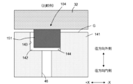
- FIG. 3 is an enlarged view of a portion corresponding to part B in FIG. 2 in a comparative example.
- FIG. 13 is a diagram showing a problem in the comparative example.
- the present invention can be suitably applied to metal injection molding machines, particularly metal injection molding machines that inject metals that have low viscosity when molten.
- the present invention can also be applied to injection molding machines that inject resin.
- the X direction refers to the axial direction of the cylinder 32
- the injection direction is called the +X direction
- the direction opposite to the injection direction is called the -X direction.
- Terms such as “forward,” “rear,” “front,” and “rear” are defined with respect to the injection direction.
- the "radial direction” is defined with respect to the central axis CL of the cylinder 32.
- the injection molding machine 1 is a horizontal metal injection molding machine that injects molten metal such as a magnesium alloy or an aluminum alloy.
- the injection molding machine 1 is generally composed of a mold clamping device 2 that clamps a mold, and an injection device 3 that heats, melts, and injects the metal material to be injected.
- the mold clamping device 2 includes a fixed platen 21 fixed on a bed (not shown) to which a fixed mold M1 is attached, and a movable platen 22 slidable on the bed to which a movable mold M2 is attached.
- a mold clamping housing (not shown) slidable on the bed is provided on the opposite side of the fixed platen 21 with respect to the movable platen 22, and the fixed platen 21 and the mold clamping housing are connected by a plurality of tie bars 23.
- a link mechanism (not shown) for opening and closing the mold is provided between the movable platen 22 and the mold clamping housing. The link mechanism is driven by an electric ball screw. Instead of the link mechanism, a hydraulic mold clamping cylinder may be provided.
- a cavity M3 filled with molten metal is formed between the fixed mold M1 and the movable mold M2.
- the injection device 3 is provided on a base (not shown).
- the injection device 3 includes a hollow cylinder 32 for heating and melting the metal material to be injected, a screw 33 housed in the cylinder 32, and a drive mechanism 34 for driving the screw 33.
- the screw 33 is coaxial with the cylinder 32.
- the screw 33 is driven to rotate by the drive mechanism 34 and is driven in the +X and -X directions.
- a heater 38 for heating and melting the metal material is provided on the outer periphery of the cylinder 32.
- the cylinder 32 is roughly divided from the rear to the front into a supply section P1, a compression section P2, and a metering section P3.
- a hopper 36 is provided in the supply section P1, and metal material in pellet form is supplied to the supply section P1.
- the metal material is sent to the compression section P2 while being heated by a heater 38.
- the metal material is compressed, heated, and kneaded in the compression section P2 to become molten, and is then transported to the metering section P3.
- the metering section P3 measures the molten metal injected in one injection cycle (shot).
- the screw 33 is equipped with a screw head 35 at its tip in the X direction.
- An injection nozzle 37 is attached to the tip of the cylinder 32, which supplies molten metal to the cavity M3.
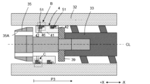
- FIG. 2 shows a partial detailed view of the front part of the cylinder 32 (an enlarged view of part A in FIG. 1).
- the upper side of the central axis CL of the cylinder 32 shows the state of the backflow prevention device 4 at the time of injection
- the lower side shows the state of the backflow prevention device 4 at the time of metering.
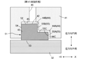
- FIG. 3A is an enlarged view of part B in FIG. 2
- FIG. 3B is an enlarged view of part C in FIG. 2, showing the positional relationship between the annular groove 42 and the piston ring 51. That is, FIG. 3A shows the state at the time of injection (the state of the backflow prevention ring 41 shown in the upper side of FIG. 2), and FIG. 3B shows the state at the time of metering (the state of the backflow prevention ring 41 shown in the lower side of FIG. 2).
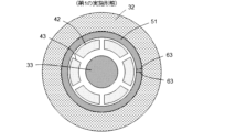
- FIG. 4 is a cross-sectional view taken along line 4-4 in FIG. 3A.
- the metering section P3 of the cylinder 32 of the injection device 3 is provided with a backflow prevention device 4 that prevents the backflow of the injected metal material.
- the backflow prevention device 4 has a backflow prevention ring 41 made of a hollow cylindrical metal member, and the backflow prevention ring 41 has an annular groove 42 that faces the inner surface of the cylinder 32 of the injection device 3.
- the backflow prevention device 4 has a piston ring 51 fitted in the annular groove 42 of the backflow prevention ring 41.
- the backflow prevention ring 41, the annular groove 42, and the piston ring 51 are coaxial with the cylinder 32.
- the annular groove 42 runs around the outer periphery of the backflow prevention ring 41 and has the same cross section at each angular position around the central axis CL of the cylinder 32.
- the backflow prevention ring 41 has two annular grooves 42, and one piston ring 51 is fitted into each annular groove 42, but there should be at least one annular groove 42 and one piston ring 51.
- the piston ring 51 is an annular sealing part fitted into the annular groove 42 of the backflow prevention ring 41, and separates the front and rear of the backflow prevention ring 41.
- the piston ring 51 is made of metal.
- the piston ring 51 has stepped ends 63, and is fitted into the annular groove 42 so that the steps of the ends 63 overlap in the circumferential direction. Therefore, the diameter of the piston ring 51 changes as the steps of the ends 63 shift circumferentially in response to the pressure applied to the inner circumferential surface 52 and outer circumferential surface 53 of the piston ring 51.
- the piston ring 51 has the same cross section at each angular position around the central axis CL of the cylinder 32, except near the ends 63.
- a presser 39 made of an annular plate is inserted into the screw head 35.
- the backflow prevention ring 41 is inserted into the screw 33 between the screw head 35 at the front in the injection direction and the presser 39 at the rear in the injection direction.
- the outer diameters of the screw head 35 and the presser 39 are larger than the inner diameter of the backflow prevention ring 41, and the X-direction length of the backflow prevention ring 41 is smaller than the X-direction separation distance between the screw head 35 and the presser 39. Therefore, the backflow prevention ring 41 can move in the X-direction while being restricted by the screw head 35 and the presser 39.
- the backflow prevention ring 41 abuts against the screw head 35, but the molten metal behind the presser 39 passes through the flow passage 35A inside the screw head 35 and is supplied to the space in front of the screw head 35. In this way, the backflow prevention ring 41 is functionally a type of valve.
- the front annular groove 42 in the injection direction is connected to a through hole 46 that penetrates the backflow prevention ring 41 in the radial direction.
- High-pressure molten metal flows into the through hole 46 and applies radial outward pressure to the piston ring 51. This pressure presses the piston ring 51 against the inner wall of the cylinder 32, improving the sealing performance of the piston ring 51.
- the rear annular groove 42 is not connected to the through hole 46. However, some of the molten metal passes through the gap between the front piston ring 51 and the cylinder 32, the gap between the backflow prevention ring 41 and the cylinder 32, and the rear annular groove 42 and exerts pressure on the inner surface 52 of the rear piston ring 51. Therefore, both the front and rear piston rings 51 contribute to improving the sealing performance.
- the through holes 46 improves sealing performance, but since a large pressure is applied to the piston ring 51, the piston ring 51 becomes more susceptible to wear. Whether or not to provide the through holes 46 is determined appropriately taking into consideration sealing performance and suppression of wear of the piston ring 51.
- the through holes 46 may be provided in both annular grooves 42, the through holes 46 may be provided only in the rear annular groove 42, or none of the annular grooves 42 may have through holes 46. However, by providing the through holes 46 only in the front annular groove 42, it becomes easier to equalize the amount of wear of the front piston ring 51 and the rear piston ring 51.
- the front annular groove 42 and the rear annular groove 42 have the same configuration, except for whether the through holes 46 are connected or not.
- the two piston rings 51 have the same configuration. Therefore, the following explanation will mainly focus on the front annular groove 42 and the piston ring 51 fitted in the front annular groove 42.
- FIG. 11A is an enlarged view of the area corresponding to the part B in FIG. 2.
- the annular groove 142 and the piston ring 151 have a rectangular cross section.
- the piston ring 151 is subjected to radially outward pressure, so that the piston ring 151 is pressed against the inner wall of the cylinder 32.
- the molten metal flows through the gap between the backflow prevention ring 141 and the cylinder 32 in the ⁇ X direction and flows into the annular groove 142, so that the piston ring 151 is pressed against the rear side surface 144 of the annular groove 142.
- the piston ring 151 is pressed against the front side surface 143 of the annular groove 142 (not shown), but since the speed of the screw 33 is higher during injection, the pressure with which the piston ring 151 is pressed against the side surface of the annular groove 142 is greater during injection.
- FIG. 11B shows the state of the piston ring 151 after it has been deformed.
- the piston ring 151 is made of a relatively soft metal. For this reason, when the piston ring 151 is pressed radially outward and in the -X direction, it may deform and part of it may enter the gap G in the -X direction between the backflow prevention ring 141 and the cylinder 32. When this happens, not only will the piston ring 151 wear out, but the part of the piston ring 151 that has entered the gap G between the backflow prevention ring 141 and the cylinder 32 may damage the cylinder 32.
- the piston ring 51 has an inner peripheral surface 52, an outer peripheral surface 53, a front side surface 54, and a rear side surface 55.
- the inner peripheral surface 52 is located at the deepest part of the annular groove 42 and separates the front side surface 54 and the rear side surface 55.
- the inner peripheral surface 52 faces the bottom surface 45 of the annular groove 42.
- the rear side surface 55 of the piston ring 51 has a step portion 55C.
- the rear side surface 55 of the piston ring 51 has a radial outer portion 55A and a radial inner portion 55B separated by the step portion 55C.
- the radial outer portion 55A, the radial inner portion 55B, and the step portion 55C face the radial outer portion 44A, the radial inner portion 44B, and the step portion 44C of the rear side surface 44 of the annular groove 42, respectively.
- the front side surface 54 is a plane perpendicular to the central axis CL of the cylinder 32, and faces the front side surface 43 of the annular groove 42.
- the radially outer portion 44A of the rear side surface 44 of the annular groove 42 is located rearward of the radially inner portion 44B in the injection direction, and the radially outer portion 55A of the rear side surface 55 of the piston ring 51 protrudes rearward in the injection direction (-X direction) relative to the radially inner portion 55B.
- the inner diameter of the piston ring 51 is larger at the rear in the injection direction than at the front in the injection direction.
- the distance D1 in the X direction between the radially outer portion 44A and the radially inner portion 44B of the rear side surface 44 of the annular groove 42 is larger than the distance D2 in the X direction between the radially outer portion 55A and the radially inner portion 55B of the rear side surface 55 of the piston ring 51.
- the rear side surface 44 of the annular groove 42 and the rear side surface 55 of the piston ring 51 can contact each other only at their respective radially inner portions 44B, 55B.
- the piston ring 51 is subjected to radially outward pressure, but in this embodiment, this pressure can be easily reduced or adjusted.
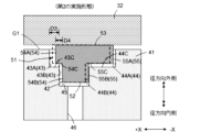
- Second Embodiment 5 is an enlarged view of a portion corresponding to portion B in FIG. 2, showing a second embodiment.
- a step portion 43C of the annular groove 42 and a step portion 54C of the piston ring 51 are also formed forward in the injection direction.
- the front side surface 43 of the annular groove 42 has a radial outer portion 43A and a radial inner portion 43B separated by the step portion 43C.
- the front side surface 54 of the piston ring 51 has a radial inner portion 54A and a radial inner portion 54B separated by the step portion 54C.
- the radially inner portion 55B of the rear side surface 55 of the piston ring 51 contacts the radially inner portion 44B of the rear side surface 44 of the annular groove 42 evenly during injection.
- the radially outer portion 44A of the rear side surface 44 of the annular groove 42 and the radially outer portion 55A of the rear side surface 55 of the piston ring 51 are perpendicular to the central axis CL of the cylinder 32.
- the pressure P3 applied to the piston ring 51 in the -X direction is converted into pressure P4 directed radially outward, thereby improving the sealing performance.
- the piston ring 51 has a housing portion 56 housed in the annular groove 42 and a protruding portion 57 located outside the annular groove 42.
- the outer peripheral surface 53 of the piston ring 51 is located radially outside the annular groove 42.
- the rear end portion 53A of the outer peripheral surface 53 in the injection direction is forward of the rearmost end portion of the housing portion 56 in the injection direction (the radially outer portion 55A of the rear side surface 55), and the outer diameter of the piston ring 51 is smaller at the rear portion in the injection direction than at the front portion in the injection direction.
- the piston ring 51 is farther away from the gap G than in the first embodiment, so that the piston ring 51 is even less likely to enter the gap G.
- the surface connecting the rear end 53A of the outer peripheral surface 53 and the outermost radial portion 58 of the rear end of the accommodating portion 56 has a cylindrical surface 60 whose central axis is the central axis CL of the cylinder 32, and an inclined surface 61 that connects the cylindrical surface 60 and the rear end 53A of the outer peripheral surface 53 and is inclined with respect to the central axis CL of the cylinder 32.
- the diameter of the cylindrical surface 60 is constant in the X direction, but may increase in the +X direction.
- Fifth Embodiment 8 is an enlarged view of a portion corresponding to portion B in FIG. 2 according to the fifth embodiment.
- the radial outermost portion 58 of the rear end of the housing portion 56 is located inside the annular groove 42, and the other points are the same as those of the fourth embodiment.
- This embodiment has the same effects as the fourth embodiment.
- the piston ring 51 is further away from the gap G than in the first and fourth embodiments, so that the piston ring 51 is even less likely to enter the gap G.
- the thickness of the protruding portion 57 gradually decreases, and eventually the cylindrical surface 60 may come into contact with the cylinder 32.
- the cylindrical surface 60 is inside the annular groove 42, it takes a longer time for the cylindrical surface 60 to come into contact with the cylinder 32 even if the piston ring 51 wears and becomes thinner. In this embodiment, the life of the piston ring 51 can be extended, and the frequency of replacing the piston ring 51 can be reduced.
- Sixth Embodiment 9 is an enlarged view of a portion corresponding to part B in FIG. 2, showing the sixth embodiment.
- a surface 62 connecting the rear end 53A of the outer peripheral surface 53 and the outermost portion 58 in the radial direction of the rear end of the accommodation portion 56 is generally inclined with respect to the central axis CL of the cylinder 32.
- the other points are the same as those of the fourth embodiment.
- the outermost portion 58 in the radial direction of the rear end of the accommodation portion 56 is located at approximately the same position in the radial direction as the opening 59 of the annular groove 42.
- This embodiment has almost the same effects as the fourth embodiment, but since the shape of the surface 62 connecting the rear end 53A of the outer peripheral surface 53 and the outermost portion 58 in the radial direction of the rear end of the accommodation portion 56 is simple, the piston ring 51 can be easily machined.
- Seventh Embodiment 10 is an enlarged view of a portion corresponding to part B in FIG. 2, showing the seventh embodiment.
- the outermost part 58 in the radial direction of the rear end of the accommodating part 56 is inside the annular groove 42, and the other points are the same as those of the sixth embodiment.
- This embodiment has the same effect as the fifth embodiment. That is, since the outermost part 58 is inside the annular groove 42, it takes a longer time for the outermost part 58 to contact the cylinder 32 even if the piston ring 51 wears and is reduced in thickness. In this embodiment, the life of the piston ring 51 can be extended, and the frequency of replacing the piston ring 51 can be reduced.
- the piston ring 51 is farther away from the gap G than in the first embodiment, so that the piston ring 51 is less likely to enter the gap G.
Landscapes
- Engineering & Computer Science (AREA)
- Mechanical Engineering (AREA)
- Manufacturing & Machinery (AREA)
- Injection Moulding Of Plastics Or The Like (AREA)
Abstract
Description
<射出成形機の全体構成>
図1は、第1の実施形態に係る射出成形機1の概略正面図を示している。射出成形機1はマグネシウム合金、アルミニウム合金などの溶融金属を射出する横型の金属射出成形機である。射出成形機1は、金型を型締めする型締装置2と、射出される金属材料を加熱溶融して射出する射出装置3と、から概略構成されている。
型締装置2は、ベッド(図示せず)上に固定され固定金型M1が取り付けられる固定盤21と、ベッド上をスライド可能で可動金型M2が取り付けられる可動盤22と、を備えている。可動盤22に関し固定盤21の反対側には、ベッド上をスライド可能な型締ハウジング(図示せず)が設けられ、固定盤21と型締ハウジングは複数本のタイバー23によって連結されている。可動盤22と型締ハウジングとの間には、金型を開閉するためのリンク機構(図示せず)が設けられている。リンク機構は電動式のボールねじで駆動される。リンク機構の代わりに、油圧式の型締シリンダを設けてもよい。固定金型M1と可動金型M2との間には、溶融金属が充填されるキャビティM3が形成される。
射出装置3は基台(図示せず)上に設けられている。射出装置3は、射出される金属材料を加熱溶融するための中空円筒のシリンダ32と、シリンダ32に収容されたスクリュ33と、スクリュ33を駆動する駆動機構34と、を備えている。スクリュ33はシリンダ32と同軸である。スクリュ33は駆動機構34によって回転駆動されるとともに+X及び-X方向に駆動される。シリンダ32の外周には金属材料を加熱溶融するヒータ38が設けられている。
図2は、シリンダ32の前方部分の部分詳細図(図1のA部拡大図)を示している。図2では便宜上、シリンダ32の中心軸CLより上側が逆流防止装置4の射出時の状態を示し、下側が逆流防止装置4の計量時の状態を示している。図3Aは図2のB部拡大図、図3Bは図2のC部拡大図であり、環状溝42とピストンリング51の位置関係を示している。すなわち、図3Aは射出時の状態(図2の上側に示す逆流防止リング41の状態)を示し、図3Bは計量時の状態(図2の下側に示す逆流防止リング41の状態)を示している。図4は図3Aの4-4線に沿った断面図である。
ここで、比較例の逆流防止装置104について説明する。図11Aは、図2のB部に相当する部位の拡大図である。環状溝142とピストンリング151は矩形断面を有している。前述のようにピストンリング151には径方向外側の圧力が掛かるため、ピストンリング151はシリンダ32の内壁に押し付けられる。また、射出時には溶融金属が逆流防止リング141とシリンダ32との間の隙間を-X方向に流れ環状溝142に流入するため、ピストンリング151は環状溝142の後部側面144に押し付けられる。計量時には、ピストンリング151は環状溝142の前部側面143に押し付けられるが(図示略)、射出時の方がスクリュ33の速度が高いため、ピストンリング151が環状溝142の側面に押し付けられる圧力は射出時の方が大きい。
主に図3Aを参照して、本実施形態の環状溝42とピストンリング51の形状についてより詳細に説明する。環状溝42は、前部側面43と後部側面44と底面45とを有している。底部45は環状溝42の最も深い部位であり、前部側面43と後部側面44とを仕切っている。後部側面44は段差部44Cを有している。後部側面44は、段差部44Cで仕切られた径方向外側部44Aと径方向内側部44Bとを有している。前部側面43はシリンダ32の中心軸CLと直交する平面である。底面45には貫通孔46が接続されている。
図5は第2の実施形態を示す、図2のB部に相当する部位の拡大図である。本実施形態では、環状溝42の段差部43Cとピストンリング51の段差部54Cが射出方向前方にも形成されている。環状溝42の前部側面43は、段差部43Cで仕切られた径方向外側部43Aと径方向内側部43Bとを有している。ピストンリング51の前部側面54は、段差部54Cで仕切られた径方向内側部54Aと径方向内側部54Bとを有している。
図6は第3の実施形態を示す、図2のB部に相当する部位の拡大図である。環状溝42の後部側面44の径方向内側部44Bとピストンリング51の後部側面55の径方向内側部55Bはシリンダ32の中心軸CLに対し同じ角度で傾斜している。環状溝42の径方向内側部44Bと底面45とは鈍角をなし、ピストンリング51の径方向内側部55Bと内周面52は鈍角をなす。このため、射出時にピストンリング51の後部側面55の径方向内側部55Bは環状溝42の後部側面44の径方向内側部44Bに均等に接触する。環状溝42の後部側面44の径方向外側部44Aとピストンリング51の後部側面55の径方向外側部55Aはシリンダ32の中心軸CLと直交している。本実施形態ではピストンリング51に-X方向に掛かる圧力P3が径方向外側を向く圧力P4に変換されるため、シール性を高めることができる。
図7は第4の実施形態を示す、図2のB部に相当する部位の拡大図である。環状溝42の後部側面44は、径方向外側部44Aと径方向内側部44Bと段差部44Cとを有し、径方向外側部44Aと径方向内側部44Bは段差部44Cで仕切られている。ピストンリング51の内径は射出方向における後部が射出方向における前部より大きい。射出時にピストンリング51が環状溝42に対して-X方向に相対移動したとき、ピストンリング51の後部側面55の径方向内側部55Bは環状溝42の後部側面44の径方向内側部44Bと接触可能である、一方、ピストンリング51の後部側面55の径方向外側部55Aは環状溝42の後部側面44の径方向外側部44Aと接触することができない。
図8は第5の実施形態を示す、図2のB部に相当する部位の拡大図である。本実施形態は収容部56の後端部の径方向における最外部58は、環状溝42の内部にあり、その他の点は第4の実施形態と同じである。本実施形態は第4の実施形態の効果を奏する。また、本実施形態は第1の実施形態及び第4の実施形態と比べて、ピストンリング51が隙間Gからさらに離れているため、ピストンリング51は一層隙間Gに侵入しにくい。
図9は第6の実施形態を示す、図2のB部に相当する部位の拡大図である。外周面53の後端部53Aと収容部56の後端部の径方向における最外部58とを結ぶ面62がシリンダ32の中心軸CLに対し全体的に傾斜している。その他の点は第4の実施形態と同じである。収容部56の後端部の径方向における最外部58は、径方向において環状溝42の開口59と略同じ位置にある。本実施形態は第4の実施形態とほぼ同様の効果を奏するが、外周面53の後端部53Aと収容部56の後端部の径方向における最外部58とを結ぶ面62の形状が単純であるため、ピストンリング51の加工が容易である。
図10は第7の実施形態を示す、図2のB部に相当する部位の拡大図である。本実施形態は収容部56の後端部の径方向における最外部58は、環状溝42の内部にあり、その他の点は第6の実施形態と同じである。本実施形態は第5の実施形態と同様の効果を奏する。すなわち、最外部58が環状溝42の内部にあるため、摩耗してピストンリング51が減肉していっても最外部58がシリンダ32に接触するまでより長時間を要する。本実施形態ではピストンリング51の寿命を伸ばすことができ、ピストンリング51の交換頻度を減らすことができる。また、本実施形態は第1の実施形態と比べて、ピストンリング51が隙間Gから離れているため、ピストンリング51は一層隙間Gに侵入しにくい。
4 逆流防止装置
32 シリンダ
33 スクリュ
41 逆流防止リング
42 環状溝
44 環状溝の後部側面
44A 環状溝の後部側面の径方向外側部
44B 環状溝の後部側面の径方向内側部
46 貫通孔
51 ピストンリング
53 外周面
53A 外周面の後端部
55 ピストンリングの後部側面
55A ピストンリングの後部側面の径方向外側部
55B ピストンリングの後部側面の径方向内側部
56 収容部
Claims (14)
- 射出装置のシリンダの内面と対向する少なくとも一つの環状溝を有する逆流防止リングと、
前記少なくとも一つの環状溝に嵌められた少なくとも一つのピストンリングと、を有し、
前記少なくとも一つの環状溝と前記少なくとも一つのピストンリングはそれぞれ、前記射出装置の射出方向における後部側面を有し、
前記少なくとも一つの環状溝の前記後部側面と前記少なくとも一つのピストンリングの前記後部側面は、それぞれの径方向内側部のみで互いに接触可能である、射出装置の逆流防止装置。 - 前記少なくとも一つのピストンリングの前記後部側面の前記径方向内側部が前記少なくとも一つの環状溝の前記後部側面の前記径方向内側部と接触したときに、前記少なくとも一つのピストンリングの前記後部側面の径方向外側部と前記少なくとも一つの環状溝の前記後部側面の径方向外側部との間にギャップが形成される、請求項1に記載の射出装置の逆流防止装置。
- 前記少なくとも一つの環状溝の前記後部側面の前記径方向外側部は、前記少なくとも一つの環状溝の前記後部側面の前記径方向内側部に対し射出方向における後方にあり、
前記少なくとも一つのピストンリングの前記後部側面の前記径方向外側部は、前記少なくとも一つのピストンリングの前記後部側面の前記径方向内側部に対し前記射出方向後方に突き出ている、請求項2に記載の逆流防止装置。 - 前記少なくとも一つの環状溝の前記後部側面の前記径方向内側部と、前記少なくとも一つのピストンリングの前記後部側面の前記径方向内側部は前記シリンダの中心軸と直交する平面である、請求項3に記載の逆流防止装置。
- 前記少なくとも一つの環状溝の前記後部側面の前記径方向外側部と前記径方向内側部との間の距離は、前記少なくとも一つのピストンリングの前記後部側面の前記径方向外側部と前記径方向内側部との間の距離より大きい、請求項4に記載の逆流防止装置。
- 前記少なくとも一つの環状溝の前記後部側面の前記径方向内側部と、前記少なくとも一つのピストンリングの前記後部側面の前記径方向内側部は前記シリンダの中心軸に対し傾斜している、請求項3に記載の逆流防止装置。
- 前記少なくとも一つのピストンリングは、前記少なくとも一つの環状溝に収容された収容部と、前記少なくとも一つの環状溝よりも径方向外側に位置する外周面と、を有し、前記外周面の前記射出方向における後端部は、前記収容部の前記射出方向における後端部に対し前記射出方向における前方にある、請求項1から6のいずれか1項に記載の逆流防止装置。
- 前記外周面の前記後端部と前記収容部の前記後端部とを結ぶ面が、
前記シリンダの中心軸を中心軸とする筒状面と、
前記筒状面の前記射出方向における前端部と前記外周面の前記後端部とを接続し、前記シリンダの中心軸に対し傾斜している傾斜面と、
を有する、請求項7に記載の射出装置の逆流防止装置。 - 前記外周面の前記後端部と前記収容部の前記後端部とを結ぶ面が前記シリンダの中心軸に対し全体的に傾斜している、請求項7に記載の射出装置の逆流防止装置。
- 前記収容部の前記後端部の径方向における最外部は、前記径方向において前記環状溝の開口と略同じ位置にある、請求項8または9に記載の射出装置の逆流防止装置。
- 前記収容部の前記後端部の径方向における最外部は前記環状溝の内部にある、請求項8または9に記載の射出装置の逆流防止装置。
- 前記少なくとも一つの環状溝と前記少なくとも一つのピストンリングはそれぞれ、前記射出方向における前部側面を有し、
前記少なくとも一つの環状溝の前記前部側面と前記少なくとも一つのピストンリングの前記前部側面は、それぞれの径方向内側部のみで互いに接触可能である、請求項1から11のいずれか1項に記載の逆流防止装置。 - 前記ピストンリングの内径は前記射出方向における後部が前記射出方向における前部より大きい、請求項1から12のいずれか1項に記載の逆流防止装置。
- 請求項1から13のいずれか1項に記載の逆流防止装置と、
前記シリンダと、
前記シリンダに収容されたスクリュと、
前記シリンダの先端に取り付けられた射出ノズルと、を有する射出装置。
Priority Applications (2)
| Application Number | Priority Date | Filing Date | Title |
|---|---|---|---|
| EP24831377.7A EP4737028A1 (en) | 2023-06-30 | 2024-04-15 | Backflow prevention device and injection device provided with same |
| CN202480040801.2A CN121358554A (zh) | 2023-06-30 | 2024-04-15 | 逆流防止装置和具有该装置的注射装置 |
Applications Claiming Priority (2)
| Application Number | Priority Date | Filing Date | Title |
|---|---|---|---|
| JP2023-108728 | 2023-06-30 | ||
| JP2023108728A JP2025007372A (ja) | 2023-06-30 | 2023-06-30 | 逆流防止装置とこれを備えた射出装置 |
Publications (1)
| Publication Number | Publication Date |
|---|---|
| WO2025004502A1 true WO2025004502A1 (ja) | 2025-01-02 |
Family
ID=93938603
Family Applications (1)
| Application Number | Title | Priority Date | Filing Date |
|---|---|---|---|
| PCT/JP2024/014911 Ceased WO2025004502A1 (ja) | 2023-06-30 | 2024-04-15 | 逆流防止装置とこれを備えた射出装置 |
Country Status (5)
| Country | Link |
|---|---|
| EP (1) | EP4737028A1 (ja) |
| JP (1) | JP2025007372A (ja) |
| CN (1) | CN121358554A (ja) |
| TW (1) | TW202504748A (ja) |
| WO (1) | WO2025004502A1 (ja) |
Citations (3)
| Publication number | Priority date | Publication date | Assignee | Title |
|---|---|---|---|---|
| JPH07314510A (ja) | 1994-05-26 | 1995-12-05 | Japan Steel Works Ltd:The | 射出成形機の逆流防止方法および逆流防止装置 |
| US5474307A (en) * | 1990-08-06 | 1995-12-12 | Richard DeBiasse | Piston ring employing elastomeric sealing member within the ring groove |
| JP2023108728A (ja) | 2022-01-26 | 2023-08-07 | キヤノン株式会社 | 画像読取装置及び画像形成システム |
-
2023
- 2023-06-30 JP JP2023108728A patent/JP2025007372A/ja active Pending
-
2024
- 2024-04-15 WO PCT/JP2024/014911 patent/WO2025004502A1/ja not_active Ceased
- 2024-04-15 EP EP24831377.7A patent/EP4737028A1/en active Pending
- 2024-04-15 CN CN202480040801.2A patent/CN121358554A/zh active Pending
- 2024-06-28 TW TW113124144A patent/TW202504748A/zh unknown
Patent Citations (3)
| Publication number | Priority date | Publication date | Assignee | Title |
|---|---|---|---|---|
| US5474307A (en) * | 1990-08-06 | 1995-12-12 | Richard DeBiasse | Piston ring employing elastomeric sealing member within the ring groove |
| JPH07314510A (ja) | 1994-05-26 | 1995-12-05 | Japan Steel Works Ltd:The | 射出成形機の逆流防止方法および逆流防止装置 |
| JP2023108728A (ja) | 2022-01-26 | 2023-08-07 | キヤノン株式会社 | 画像読取装置及び画像形成システム |
Also Published As
| Publication number | Publication date |
|---|---|
| EP4737028A1 (en) | 2026-05-06 |
| TW202504748A (zh) | 2025-02-01 |
| CN121358554A (zh) | 2026-01-16 |
| JP2025007372A (ja) | 2025-01-17 |
Similar Documents
| Publication | Publication Date | Title |
|---|---|---|
| CN100540183C (zh) | 金属材料注射成型机的改进注射喷嘴 | |
| US8815142B2 (en) | Method of manufacturing a resin molded gear by injection molding | |
| WO2025004502A1 (ja) | 逆流防止装置とこれを備えた射出装置 | |
| JP2006070926A (ja) | 円錐ころ軸受用保持器 | |
| WO2025004501A1 (ja) | 逆流防止装置とこれを備えた射出装置 | |
| CN110667059B (zh) | 一种改进型注塑机用螺杆止逆环机构 | |
| JP5576732B2 (ja) | スプルーブッシュとその製造方法 | |
| JP6730163B2 (ja) | ダイカスト成形用射出プランジャおよびダイカスト成形用射出装置 | |
| JP6753188B2 (ja) | ダイカストマシンのプランジャチップ構造 | |
| WO2024190322A1 (ja) | 射出シリンダとこれを備える射出成形機、及び分割式射出シリンダの構成部品 | |
| JP2015083319A (ja) | ダイカスト用スリーブ | |
| JP6753187B2 (ja) | ダイカストマシンのプランジャチップ構造 | |
| JP2000202878A (ja) | Lim成形機用スクリュ―ヘッド | |
| JP4464678B2 (ja) | ダイカストマシン | |
| JP3730129B2 (ja) | 軽合金射出成形装置のノズル装置 | |
| JP5829537B2 (ja) | スクリューヘッド、その製造方法、および射出装置 | |
| JP2024179869A (ja) | 型締装置及び成形機 | |
| JP2026074530A (ja) | 油圧シリンダユニットおよび型締装置 | |
| JP2002361708A (ja) | 潤滑油供給機構 | |
| JPH08238654A (ja) | 射出成形機の逆流防止機構 | |
| CN113118410A (zh) | 柱塞头、注射装置以及注射方法 | |
| JP2006281745A (ja) | 射出成形用金型 | |
| JP2007216238A (ja) | ライナ固定装置を備えたシリンダブロック鋳造用金型 | |
| JPH04267118A (ja) | 射出成形機のスクリュヘッド | |
| JPH0985791A (ja) | 射出成形機のスクリューヘッド |
Legal Events
| Date | Code | Title | Description |
|---|---|---|---|
| 121 | Ep: the epo has been informed by wipo that ep was designated in this application |
Ref document number: 24831377 Country of ref document: EP Kind code of ref document: A1 |
|
| WWE | Wipo information: entry into national phase |
Ref document number: 2024831377 Country of ref document: EP |
|
| NENP | Non-entry into the national phase |
Ref country code: DE |
|
| ENP | Entry into the national phase |
Ref document number: 2024831377 Country of ref document: EP Effective date: 20260130 |
|
| ENP | Entry into the national phase |
Ref document number: 2024831377 Country of ref document: EP Effective date: 20260130 |