WO2025004498A1 - エンコーダ - Google Patents
エンコーダ Download PDFInfo
- Publication number
- WO2025004498A1 WO2025004498A1 PCT/JP2024/014737 JP2024014737W WO2025004498A1 WO 2025004498 A1 WO2025004498 A1 WO 2025004498A1 JP 2024014737 W JP2024014737 W JP 2024014737W WO 2025004498 A1 WO2025004498 A1 WO 2025004498A1
- Authority
- WO
- WIPO (PCT)
- Prior art keywords
- magnet
- fixing screw
- rotation axis
- head
- direction along
- Prior art date
- Legal status (The legal status is an assumption and is not a legal conclusion. Google has not performed a legal analysis and makes no representation as to the accuracy of the status listed.)
- Ceased
Links
Images




Classifications
-
- G—PHYSICS
- G01—MEASURING; TESTING
- G01D—MEASURING NOT SPECIALLY ADAPTED FOR A SPECIFIC VARIABLE; ARRANGEMENTS FOR MEASURING TWO OR MORE VARIABLES NOT COVERED IN A SINGLE OTHER SUBCLASS; TARIFF METERING APPARATUS; MEASURING OR TESTING NOT OTHERWISE PROVIDED FOR
- G01D5/00—Mechanical means for transferring the output of a sensing member; Means for converting the output of a sensing member to another variable where the form or nature of the sensing member does not constrain the means for converting; Transducers not specially adapted for a specific variable
- G01D5/26—Mechanical means for transferring the output of a sensing member; Means for converting the output of a sensing member to another variable where the form or nature of the sensing member does not constrain the means for converting; Transducers not specially adapted for a specific variable characterised by optical transfer means, i.e. using infrared, visible, or ultraviolet light
- G01D5/32—Mechanical means for transferring the output of a sensing member; Means for converting the output of a sensing member to another variable where the form or nature of the sensing member does not constrain the means for converting; Transducers not specially adapted for a specific variable characterised by optical transfer means, i.e. using infrared, visible, or ultraviolet light with attenuation or whole or partial obturation of beams of light
- G01D5/34—Mechanical means for transferring the output of a sensing member; Means for converting the output of a sensing member to another variable where the form or nature of the sensing member does not constrain the means for converting; Transducers not specially adapted for a specific variable characterised by optical transfer means, i.e. using infrared, visible, or ultraviolet light with attenuation or whole or partial obturation of beams of light the beams of light being detected by photocells
- G01D5/347—Mechanical means for transferring the output of a sensing member; Means for converting the output of a sensing member to another variable where the form or nature of the sensing member does not constrain the means for converting; Transducers not specially adapted for a specific variable characterised by optical transfer means, i.e. using infrared, visible, or ultraviolet light with attenuation or whole or partial obturation of beams of light the beams of light being detected by photocells using displacement encoding scales
- G01D5/3473—Circular or rotary encoders
-
- G—PHYSICS
- G01—MEASURING; TESTING
- G01D—MEASURING NOT SPECIALLY ADAPTED FOR A SPECIFIC VARIABLE; ARRANGEMENTS FOR MEASURING TWO OR MORE VARIABLES NOT COVERED IN A SINGLE OTHER SUBCLASS; TARIFF METERING APPARATUS; MEASURING OR TESTING NOT OTHERWISE PROVIDED FOR
- G01D5/00—Mechanical means for transferring the output of a sensing member; Means for converting the output of a sensing member to another variable where the form or nature of the sensing member does not constrain the means for converting; Transducers not specially adapted for a specific variable
- G01D5/26—Mechanical means for transferring the output of a sensing member; Means for converting the output of a sensing member to another variable where the form or nature of the sensing member does not constrain the means for converting; Transducers not specially adapted for a specific variable characterised by optical transfer means, i.e. using infrared, visible, or ultraviolet light
- G01D5/32—Mechanical means for transferring the output of a sensing member; Means for converting the output of a sensing member to another variable where the form or nature of the sensing member does not constrain the means for converting; Transducers not specially adapted for a specific variable characterised by optical transfer means, i.e. using infrared, visible, or ultraviolet light with attenuation or whole or partial obturation of beams of light
- G01D5/34—Mechanical means for transferring the output of a sensing member; Means for converting the output of a sensing member to another variable where the form or nature of the sensing member does not constrain the means for converting; Transducers not specially adapted for a specific variable characterised by optical transfer means, i.e. using infrared, visible, or ultraviolet light with attenuation or whole or partial obturation of beams of light the beams of light being detected by photocells
- G01D5/347—Mechanical means for transferring the output of a sensing member; Means for converting the output of a sensing member to another variable where the form or nature of the sensing member does not constrain the means for converting; Transducers not specially adapted for a specific variable characterised by optical transfer means, i.e. using infrared, visible, or ultraviolet light with attenuation or whole or partial obturation of beams of light the beams of light being detected by photocells using displacement encoding scales
Definitions
- This disclosure relates to an encoder.
- an optical battery-less type encoder that uses a circular magnet that rotates around a rotation axis, a power generating element including a magnetic wire and a coil, a light source and a light receiving element (see, for example, Patent Document 1).
- the magnetic field generated by the rotating magnet is used to generate electricity in a power generating element such as a Wiegand wire sensor.
- the objective of this disclosure is to provide an optical, battery-less encoder that can efficiently utilize the magnetic field generated by a magnet.
- An encoder is an optical battery-less type encoder that detects rotation around the axis of rotation of a shaft.
- the encoder according to one embodiment of the present disclosure includes a light source that emits light, a rotating plate that rotates with the shaft and generates modulated light by modulating the light, and a light receiving element that receives the modulated light.
- the encoder according to one embodiment of the present disclosure also includes a fixing screw that is screwed into a screw hole formed in the end face of the shaft, a support member that is fixed to the shaft by the fixing screw and supports the rotating plate, a magnet placed on the fixing screw, and a magnetic sensor that generates power using the magnetic field generated by the magnet.
- the fixing screw has a threaded portion that is screwed into the screw hole, and a head that is connected to the threaded portion and has a placement portion in which the magnet is placed.
- This disclosure provides an optical, battery-less encoder that can efficiently utilize the magnetic field generated by a magnet.
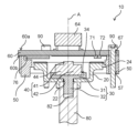
- FIG. 1 is a cross-sectional view showing an overall configuration of an encoder according to a first embodiment.
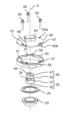
- 1 is an exploded perspective view showing an overall configuration of an encoder according to a first embodiment;
- 4 is a plan view showing the configuration of a magnet and a fixing screw according to the first embodiment.
- FIG. 1 is a schematic diagram illustrating an example of a configuration of a magnetic sensor according to a first embodiment;
- FIG. 11 is a perspective view showing the configuration of a fixing screw and a magnet according to a second embodiment.
- FIG. 11 is a plan view showing a configuration of a fixing screw according to the second embodiment.
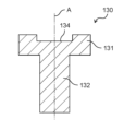
- FIG. 11 is a cross-sectional view showing a configuration of a fixing screw according to a second embodiment.
- FIG. 13 is a plan view showing the configuration of a magnet according to a first modified example of the second embodiment.
- FIG. 13 is a plan view showing a configuration of a fixing screw according to a second modification of the second embodiment.
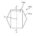
- FIG. 13 is a cross-sectional view showing a configuration of a fixing screw according to a second modified example of the second embodiment.
- each figure is a schematic diagram and is not necessarily a precise illustration.
- the same reference numerals are used for substantially the same configuration, and duplicate explanations are omitted or simplified.
- terms indicating the relationship between elements such as perpendicular and parallel
- terms indicating the shape of elements such as polygon, regular hexagon, ring, rectangle, columnar, and disk-like, are not expressions that only express a strict meaning, but also expressions that include a range of substantial equivalence, for example, differences of about a few percent.
- FIG. 1 is a cross-sectional view showing the overall configuration of the encoder 10 according to the present embodiment.
- Fig. 1 also shows a shaft 80 to which the encoder 10 is attached.
- Fig. 1 shows a cross section including a rotation axis A which is the center of rotation of the shaft 80.
- Fig. 2 is an exploded perspective view showing the overall configuration of the encoder 10 according to the present embodiment.
- the encoder 10 in this embodiment is an optical, battery-less type encoder that detects rotation about the rotation axis A of the shaft 80 shown in FIG. 1.
- the encoder 10 includes a support member 20, a rotating plate 24, a fixing screw 30, a magnet 40, a frame 50, a mounting board 60, a magnetic sensor 64, a control circuit 76, a light source 71, a light receiving element 72, and a screw 90.
- the shaft 80 is a columnar member that rotates about the rotation axis A.
- the shaft 80 has a cylindrical shape.
- the shaft 80 may be, for example, the rotating shaft of a motor.
- the encoder 10 may also include the shaft 80 as a component.
- a screw hole 82 is formed in the end face (in other words, the bottom face) of the shaft 80.
- the screw hole 82 is formed from the end face of the shaft 80 along the rotation axis A.
- a fixing screw 30 is screwed into the screw hole 82 along the rotation axis A.
- the support member 20 is a member that supports the rotating plate 24.
- the support member 20 is fixed to the shaft 80 by the fixing screw 30.
- the support member 20 has an annular shape and has an annular flat portion.
- the rotating plate 24 is disposed on the annular flat portion of the support member 20.
- a through hole 22 is formed in the center of the support member 20.
- the diameter of the through hole 22 is smaller than the diameter of the end face of the shaft 80 and larger than the diameter of the threaded portion 32 of the fixing screw 30.
- the threaded portion 32 of the fixing screw 30 inserted into the through hole 22 of the support member 20 is screwed into the screw hole 82 of the shaft 80.
- the support member 20 is sandwiched between the head 31 of the fixing screw 30 and the end face of the shaft 80, thereby fixing the support member 20 to the shaft 80.
- the support member 20 is fixed to the shaft 80 by the fixing screw 30 disposed on the rotation axis A.
- This allows the dimension of the support member 20 in the direction along the rotation axis A to be reduced compared to when the support member 20 is fixed to the shaft 80 using a set screw or the like that is screwed into the shaft 80 in a direction perpendicular to the rotation axis A. This allows the encoder 10 to be made thinner.
- the fixing screw 30 can be accessed from the direction of the rotation axis A.
- the support member 20 and the fixing screw 30 can be accessed from the opening of the case, making it easy to assemble the support member 20 and the fixing screw 30.
- the support member 20 fixed to the shaft 80 in the manner described above rotates together with the shaft 80 around the rotation axis A.
- the rotating plate 24 supported by the support member 20 rotates together with the shaft 80, and generates modulated light by modulating the light emitted by the light source 71.
- the rotating plate 24 has an annular shape centered on the rotation axis A.
- the reflectance of the position on the rotating plate 24 where the light is incident is modulated according to the position in the circumferential direction of the rotating plate 24.
- the rotating plate 24 is a reflective rotating plate.
- the rotating plate 24 emits reflected light in which the intensity of the incident light is modulated. This reflected light is an example of modulated light generated by the rotating plate 24.
- the rotating plate 24 may be a transmissive rotating plate in which the transmittance of the position where the light is incident is modulated according to the position in the circumferential direction of the rotating plate 24.
- the rotating plate 24 is a transmissive rotating plate, the transmitted light that passes through the rotating plate 24 can be used as modulated light.
- the light source 71 is an element that emits light.
- the light emitted by the light source 71 is incident on the rotating plate 24.
- the light source 71 is mounted on the mounting board 60.
- an LED (Light Emitting Diode) or the like can be used as the light source 71.
- the light receiving element 72 is an element that receives modulated light generated by the rotating plate 24.
- the light receiving element 72 is mounted on the mounting substrate 60.
- a photodiode can be used as the light receiving element 72.
- the fixing screw 30 is a member that is screwed into a screw hole 82 formed in the end face of the shaft 80.
- the fixing screw 30 has a threaded portion 32 that is screwed into the screw hole 82, and a head 31 that is connected to the threaded portion 32 and has a placement portion 34 in which the magnet 40 is placed.
- the central axis of the threaded portion 32 coincides with the rotation axis A.
- the threaded portion 32 of the fixing screw 30 rotates around the rotation axis A together with the shaft 80.
- the placement portion 34 is a recess that is recessed in a direction along the rotation axis A.
- the placement portion 34 is placed in an area that includes the rotation axis A. As a result, the magnet 40 can be accurately placed on the rotation axis A.
- the magnet 40 is a magnetic member that is placed on the fixing screw 30. More specifically, the magnet 40 is placed on the placement portion 34 of the fixing screw 30.
- the magnet 40 has a north pole 41 and a south pole 42.
- the magnet 40 also has a protrusion 44 that protrudes in a direction away from the fixing screw 30 along the rotation axis A.
- FIG. 3 is a plan view showing the configuration of the magnet 40 and the fixing screw 30 according to this embodiment.
- FIG. 3 shows a plan view of the magnet 40 and the fixing screw 30 as viewed from the direction along the rotation axis A.
- the magnet 40 is placed in the placement portion 34 of the fixing screw 30.
- the placement portion 34 is a recess that is recessed in the direction along the rotation axis A, and at least a part of the magnet 40 is inserted into the placement portion 34, which is a recess.
- the magnet 40 may also be fitted into the placement portion 34, which is a recess. This allows the magnet 40 to be accurately positioned at a predetermined position.
- the center or center of gravity of the magnet 40 may be located on the rotation axis A when viewed from the direction along the rotation axis A.
- the center or center of gravity of the protruding portion 44 of the magnet 40 may also be located on the rotation axis A when viewed from the direction along the rotation axis A.
- the magnet 40 may be fixed to the fixing screw 30 using a joining member such as an adhesive.
- the head 31 of the fixing screw 30 has two parallel sides LS31, LS32 and two parallel sides LL31, LL32. This allows the fixing screw 30 to be easily screwed into the threaded hole 82 of the shaft 80 using a tool that matches the shape of the head 31.
- the shape of the magnet 40 When viewed from the direction along the axis of rotation A, the shape of the magnet 40 is rectangular with two short sides LS41, LS42 and two long sides LL41, LL42, and the two short sides LS41, LS42 face the two sides LS31, LS32 of the head 31, respectively. This makes it possible to maximize the dimensions of the long sides LL41, LL42 of the magnet 40 without making them larger than the dimensions of the head 31 of the fixing screw 30.
- the length of the two long sides LL41, LL42 of the magnet 40 is equal to or less than the distance between the two sides LS31, LS32. This makes it possible to position the magnet 40 relative to the fixing screw 30 so that the magnet 40 does not protrude from the two sides LS31, LS32 of the fixing screw 30 when viewed from the direction along the rotation axis A. This makes it easier to rotate the fixing screw 30 using a jig or the like that matches the shape of the head 31.
- the magnet 40 when viewed from the direction along the rotation axis A, the magnet 40 may be disposed inside the outer edge of the head 31 of the fixing screw 30. This allows the fixing screw 30 to be rotated using a general-purpose tool such as a socket wrench.
- the magnetic sensor 64 is a power generating element that generates power using the magnetic field generated by the magnet 40.
- the magnetic sensor 64 does not rotate together with the shaft 80 or the like.
- the magnetic sensor 64 is mounted on the mounting board 60 and disposed on the rotation axis A as shown in Figs. 1 and 2.
- the magnetic sensor 64 is fixed to the main body of the motor via the mounting board 60 and the frame 50.
- the magnetic sensor 64 is not particularly limited as long as it is a power generating element that generates power using the magnetic field generated by the magnet 40.
- the magnetic sensor 64 is a Wiegand wire sensor. The configuration of the magnetic sensor 64 according to this embodiment will be described with reference to Fig. 4.
- FIG. 4 is a schematic diagram showing an example of the configuration of the magnetic sensor 64 according to this embodiment.
- the magnetic sensor 64 has a magnetic member 65 and a coil 66.
- the magnetic member 65 is a Wiegand wire that generates a large Barkhausen effect when an external magnetic field changes.
- the magnetic member 65 is disposed on the axis of rotation A and extends in a direction perpendicular to the axis of rotation A.
- the coil 66 is a conducting wire wound around the magnetic member 65.
- Wiegand wire is a magnetic material whose magnetization aligns to one side in the longitudinal direction when a magnetic field of a predetermined value or greater is applied along the longitudinal direction of the Wiegand wire.
- the magnetization direction of the Wiegand wire suddenly reverses, and a voltage pulse is induced at both ends of the coil 66 wound around the Wiegand wire.
- the magnetic sensor 64 generates electricity, and the output of the magnetic sensor 64 changes in response to the change in the direction of the magnetic field caused by the rotation of the magnet 40 in the magnetic sensor 64.
- the magnetic sensor 64 may have, for example, a magnetic collector.
- the magnetic collector is made of, for example, a soft magnetic material such as ferrite, and is disposed near both ends of the magnetic member 65.
- the magnetic collector has, for example, an annular shape, and surrounds the end or the vicinity of the end of the magnetic member 65.
- the mounting board 60 is a board on which the magnetic sensor 64 and the like are mounted.
- the mounting board 60 is a disk-shaped board and has a first main surface 60a, a second main surface 60b, three through holes 67, and two through holes 68 (see FIG. 2).
- the first main surface 60a is the main surface on which the magnetic sensor 64 is arranged.
- the second main surface 60b is the back surface of the first main surface 60a and faces the rotating plate 24 and the frame 50.
- the control circuit 76, the light source 71, and the light receiving element 72 are arranged on the second main surface 60b.
- the through hole 67 is a hole into which the screw 90 is inserted.
- the through hole 68 is a hole into which the protrusion 58 formed on the frame 50 is inserted.
- the mounting board 60 is fixed to the frame 50 using the screw 90 or the like.
- the screw 90 is screwed into a screw hole formed in the body of the motor. This fixes the mounting board 60 to the motor body.
- the control circuit 76 is a circuit that detects the rotation of the shaft 80 by controlling the light source 71 and the like.
- the control circuit 76 operates using the power generated by the magnetic sensor 64.
- the frame 50 is a member on which the mounting board 60 is disposed.
- the frame 50 is fixed to the body of the motor.
- the frame 50 has three through holes 57 and two protrusions 58. Screws 90 are inserted into the through holes 57.
- the protrusions 58 protrude toward the mounting board 60 and are inserted into the through holes 68 of the mounting board 60.
- the protrusions 58 and the through holes 68 can be used to position the mounting board 60 relative to the frame 50.
- the encoder 10 has a fixing screw 30 that is screwed into a screw hole 82 formed in the end face of a shaft 80 that rotates about a rotation axis A.
- the head 31 of the fixing screw 30 has a placement portion 34 in which a magnet 40 is disposed.
- the fixing screw 30 allows the fixing screw 30 to rotate around the rotation axis A.
- the magnet 40 can be easily arranged on the rotation axis A of the shaft 80. Therefore, for example, when the magnetic sensor 64 is arranged on the rotation axis A, the strength of the magnetic field in the magnetic sensor 64 can be increased. In other words, the encoder 10 according to this embodiment can efficiently utilize the magnetic field generated by the magnet 40. Furthermore, by forming the arrangement portion 34 in a member having a relatively simple structure such as the fixing screw 30, processing is easier than when forming an arrangement portion in a member having a relatively complex structure such as the support member 20.
- the encoder 10 can reduce the obstruction of the light modulation effect of the rotating plate 24.
- the end edge of the head 31 of the fixing screw 30 when viewed from a direction along the rotation axis A, the end edge of the head 31 of the fixing screw 30 has two parallel sides LS31, LS32, and two parallel sides LL31, LL32.
- the shape of the magnet 40 is rectangular with two short sides LS41, LS42 and two long sides LL41, LL42 when viewed from the direction along the rotation axis A. Furthermore, the two short sides LS41, LS42 face the two sides LS31, LS32 of the head 31 of the fixing screw 30, respectively.
- the length of the two long sides LL41, LL42 of the magnet 40 is equal to or less than the distance between the two sides LS31, LS32 of the head 31 of the fixing screw 30.
- the magnet 40 when viewed from a direction along the axis of rotation A, the magnet 40 is positioned inside the outer edge of the head 31 of the fixing screw 30.
- the magnetic sensor 64 is positioned on the axis of rotation A.
- the encoder 10 can efficiently utilize the magnetic field generated by the magnet 40.
- the magnetic sensor 64 has a magnetic member 65 that generates a large Barkhausen effect in response to changes in the external magnetic field.
- the magnetic sensor 64 to be a Wiegand wire sensor, so that even if the rotational frequency of the magnetic field generated by the magnet 40 fixed to the shaft 80 is low, the magnetic sensor 64 can output a high voltage.
- Embodiment 2 An encoder according to embodiment 2 will be described.
- the encoder according to this embodiment differs from the fixing screw 30 and magnet 40 of the encoder 10 according to embodiment 1 mainly in the configurations of the fixing screw 130 and magnet 140.
- the encoder according to this embodiment will be described below with reference to Figures 5 to 7, focusing on the differences from the encoder 10 according to embodiment 1.
- FIG. 5 is a perspective view showing the configuration of the fixing screw 130 and magnet 140 according to this embodiment.
- FIGS. 6 and 7 are a plan view and a cross-sectional view, respectively, showing the configuration of the fixing screw 130 according to this embodiment.
- the outline of the magnet 140 placed on the fixing screw 130 is shown by a dashed line.
- FIG. 7 a cross section of the fixing screw 130 taken along line VII-VII shown in FIG. 6 is shown.
- the encoder according to this embodiment includes a fixing screw 130 and a magnet 140.
- the fixing screw 130 according to this embodiment has a threaded portion 132 and a head 131 connected to the threaded portion 132 and having an arrangement portion 134 in which the magnet 140 is arranged.
- the threaded portion 132 has a similar configuration to the threaded portion 32 according to embodiment 1.
- the contour of the head 131 of the fixing screw 130 has two parallel sides LS131, LS132 when viewed from the direction along the rotation axis A. More specifically, when viewed from the direction along the rotation axis A, the shape of the head 131 of the fixing screw 130 is a regular hexagon. This allows the threaded portion 132 of the fixing screw 130 to be easily screwed into the threaded hole 82 of the shaft 80 using a general-purpose tool such as a hexagonal wrench.
- the placement portion 134 of the fixing screw 130 is a recess that is recessed in a direction along the rotation axis A, and at least one end of the recess extends to the end of the head 131 when viewed from the direction along the rotation axis A.
- both longitudinal ends of the recess extend to the end of the head 131.
- the shape of the magnet 140 when viewed from the direction along the rotation axis A, is a rectangle having two short sides LS141, LS142 and two long sides LL141, LL142.
- the length of the two long sides LL141, LL142 is greater than the distance between the two sides LS131, LS132 of the fixing screw 130.
- the longitudinal dimension of the magnet 140 when viewed from the direction along the rotation axis A, may be greater than the dimension of the head 131 of the fixing screw 130. This allows the volume of the magnet 140 to be increased, thereby increasing the strength of the magnetic field generated by the magnet 140.
- the length of the two long sides LL141, LL142 of magnet 140 when viewed from the direction along rotation axis A is greater than the distance between two sides LS131, LS132 of fixing screw 130, but the dimensions of the magnet according to the present disclosure are not limited to this.
- the length of the two long sides of the magnet according to the present disclosure may be less than the distance between two sides LS131, LS132 of fixing screw 130.
- FIG. 8 is a plan view showing the configuration of magnet 240 according to Variation 1 of the present embodiment. In FIG. 8, the outline of magnet 240 is shown by a dashed line, and fixing screw 130 is shown by a solid line.
- the fixing screw 130 shown in FIG. 8 has the same configuration as the fixing screw 130 according to the present embodiment described above.
- the magnet 240 according to the first modified example is rectangular with two short sides LS241, LS242 and two long sides LL241, LL242. Furthermore, the two short sides LS241, LS242 face the two sides LS131, LS132 of the head 131, respectively.
- the length of the two long sides LL241, LL242 of the magnet 240 in Modification 1 is equal to or less than the distance between the two sides LS131, LS132 of the fixing screw 130. This makes it possible to position the magnet 240 relative to the fixing screw 130 so that the magnet 240 (its short sides LS241, LS242) does not protrude from the two sides LS131, LS132 of the fixing screw 130 when viewed from the direction along the rotation axis A. This makes it easier to rotate the fixing screw 130 using a jig or the like that matches the shape of the head 131.
- the arrangement portion 134 is a recess that is recessed in a direction along the rotation axis A, and both ends of the recess extend to the end of the head 131 of the fixing screw 130 when viewed from the direction along the rotation axis A, but the configuration of the fixing screw according to this disclosure is not limited to this.
- the arrangement portion of the fixing screw according to this disclosure may be a recess that is recessed in a direction along the rotation axis A, and only one end of the recess may extend to the end of the head of the fixing screw according to this disclosure when viewed from the direction along the rotation axis A.
- Figures 9 and 10 are a plan view and a cross-sectional view, respectively, showing the configuration of the fixing screw 130a according to the second modified example of this embodiment.
- Figure 10 shows a cross section of the fixing screw 130a taken along the line X-X shown in Figure 9.
- the fixing screw 130a in variant example 2 has a threaded portion 132 and a head 131a that is connected to the threaded portion 132 and has an arrangement portion 134a in which a magnet 240 or the like is arranged.
- the positioning portion 134a is a recess that is recessed in a direction along the rotation axis A, and only one of the two longitudinal ends of the recess extends to the end of the head 131a when viewed from the direction along the rotation axis A.
- the positioning portion 134a of the fixing screw 130a of the second modified example having such a configuration can also be easily formed by a method such as header processing, similar to the positioning portion 134 of the fixing screw 130 of the present embodiment.
- the arrangement portion 34, 134, 134a of the fixing screw 30, 130, 130a in each of the above embodiments is a recess, but the configuration of the arrangement portion is not limited to this.
- the arrangement portion may be a convex portion that protrudes along the rotation axis A, and the magnet may be formed with a recess into which the convex portion is inserted.
- the shape of the head 131 of the fixing screw 130 is a regular hexagon when viewed from a direction along the rotation axis A, but the shape of the head 131 is not limited to this.
- the shape of the head of the fixing screw may be a polygon. Even with such a fixing screw, the fixing screw can be easily rotated using a jig or the like that matches the shape of the head of the fixing screw.
- the magnetic sensor 64 in each of the above embodiments has a Wiegand wire
- the configuration of the magnetic sensor is not limited to this.
- the magnetic sensor may be a coil that does not have a Wiegand wire.
- the encoder 10 is an optical battery-less type encoder 10 that detects the rotation of the shaft 80 around the rotation axis A.
- the encoder 10 includes a light source 71 that emits light, a rotating plate 24 that rotates with the shaft 80 and generates modulated light by modulating the light, and a light receiving element 72 that receives the modulated light.
- the encoder 10 also includes a fixing screw 30, 130, or 130a that is screwed into a screw hole 82 formed on the end face of the shaft 80, and a support member 20 that is fixed to the shaft 80 by the fixing screw 30, 130, or 130a and supports the rotating plate 24.
- the encoder 10 also includes a magnet 40, 140, or 240 that is placed on the fixing screw 30, 130, or 130a, and a magnetic sensor 64 that generates power using the magnetic field generated by the magnet 40, 140, or 240.
- the fixing screw 30, 130, or 130a has a threaded portion 32 or 132 that is screwed into the screw hole 82, and a head 31, 131, or 131a that is connected to the threaded portion 32 or 132 and has an arrangement portion 34, 134, or 134a in which the magnet 40, 140, or 240 is arranged.
- the magnet 40, 140, or 240 can be easily arranged on the rotation axis A of the shaft 80. Therefore, for example, when the magnetic sensor 64 is arranged on the rotation axis A, the strength of the magnetic field in the magnetic sensor 64 can be increased. In other words, the magnetic field generated by the magnet 40, 140, or 240 can be efficiently used.
- arrangement portion 34, 134, or 134a in a member having a relatively simple structure such as the fixing screw 30, 130, or 130a, processing is easier than when forming an arrangement portion in a member having a relatively complex structure such as the support member 20.
- the magnet 40, 140, or 240 by placing the magnet 40, 140, or 240 on the fixing screw 30, 130, or 130a, it is possible to reduce adhesion of the adhesive used to join the magnet 40, 140, or 240 to the rotating plate 24 compared to when the magnet 40, 140, or 240 is placed on the support member 20, etc. Therefore, it is possible to reduce the obstruction of the light modulation effect of the rotating plate 24.
- the arrangement portion 134 or 134a is a recess that is recessed in a direction along the rotation axis A, and when viewed from the direction along the rotation axis A, at least one end of the recess extends to the end of the head 131 or 131a.
- Example 2 can be applied to Example 1.
- the end edge of the head 31, 131, or 131a has two parallel sides LS31, LS32, two parallel sides LL31, LL32, or two parallel sides LS131, LS132.
- Example 3 can be applied to Example 1 or Example 2.
- the shape of the magnet 40, 140, or 240 is a rectangle having two short sides LS41, LS42, two short sides LS141, LS142, or two short sides LS241, LS242, and two long sides LL41, LL42, two long sides LL141, LL142, or two long sides LL241, LL242.
- the two short sides LS41, LS42, the two short sides LS141, LS142, or the two short sides LS241, LS242 face the two sides LS31, LS32, or the two sides LS131, LS132 of the head 31, 131, or 131a, respectively.
- Example 4 This allows the dimensions of the long sides LL41, LL42, or the long sides LL241, LL242, of the magnets 40 or 240 to be increased to the maximum extent possible without exceeding the dimensions of the heads 31, 131, or 131a of the fixing screws 30, 130, or 130a.
- the configuration of Example 4 is applicable to Example 3.
- the length of the two long sides LL41 and LL42 or the two long sides LL241 and LL242 is less than or equal to the distance between the two sides LS31 and LS32 or the distance between the two sides LS131 and LS132.
- Example 5 can be applied to Example 4.
- Example 6 When viewed from a direction along the rotation axis A, the shape of the head 131 or 131a is polygonal.
- Example 6 This allows the fixing screw 130 or 130a to be easily screwed into the screw hole 82 of the shaft 80 using a tool that matches the shape of the head 131 or 131a.
- the configuration of Example 6 can be applied to any of Examples 1 to 5.
- Example 7 When viewed from a direction along the rotation axis A, the shape of the head 131 or 131a is a regular hexagon.
- Example 7 can be applied to any of Examples 1 to 6.
- Example 8 When viewed from a direction along the rotation axis A, the magnet 40 or 240 is positioned inside the outer edge of the head 31, 131, or 131a.
- Example 8 This allows the fixing screw 30, 130, or 130a to be rotated using a general-purpose tool such as a socket wrench.
- the configuration of Example 8 can be applied to any of Examples 1 to 7.
- the magnetic sensor 64 is positioned on the rotation axis A.
- Example 9 can be applied to any of Examples 1 to 8.
- the magnetic sensor 64 has a magnetic member 65 that generates the large Barkhausen effect when an external magnetic field changes.
- Example 10 can be applied to any of Examples 1 to 9.
- the encoder disclosed herein can be used, for example, as a detector for detecting the rotation of a motor shaft, etc.
Landscapes
- Physics & Mathematics (AREA)
- General Physics & Mathematics (AREA)
- Transmission And Conversion Of Sensor Element Output (AREA)
Priority Applications (2)
| Application Number | Priority Date | Filing Date | Title |
|---|---|---|---|
| CN202480041780.6A CN121368707A (zh) | 2023-06-30 | 2024-04-11 | 编码器 |
| JP2025529461A JPWO2025004498A1 (https=) | 2023-06-30 | 2024-04-11 |
Applications Claiming Priority (2)
| Application Number | Priority Date | Filing Date | Title |
|---|---|---|---|
| JP2023-108581 | 2023-06-30 | ||
| JP2023108581 | 2023-06-30 |
Publications (1)
| Publication Number | Publication Date |
|---|---|
| WO2025004498A1 true WO2025004498A1 (ja) | 2025-01-02 |
Family
ID=93938614
Family Applications (1)
| Application Number | Title | Priority Date | Filing Date |
|---|---|---|---|
| PCT/JP2024/014737 Ceased WO2025004498A1 (ja) | 2023-06-30 | 2024-04-11 | エンコーダ |
Country Status (3)
| Country | Link |
|---|---|
| JP (1) | JPWO2025004498A1 (https=) |
| CN (1) | CN121368707A (https=) |
| WO (1) | WO2025004498A1 (https=) |
Citations (3)
| Publication number | Priority date | Publication date | Assignee | Title |
|---|---|---|---|---|
| US9528856B2 (en) | 2012-04-30 | 2016-12-27 | Fritz Kübler GmbH Zähl- und Sensortechnik | Energy-self-sufficient multiturn rotary encoder and method for determining a unique position of an encoder shaft by means of the multiturn rotary encoder |
| JP2020038081A (ja) * | 2018-09-03 | 2020-03-12 | 富士電機株式会社 | エンコーダ |
| WO2023026732A1 (ja) * | 2021-08-24 | 2023-03-02 | パナソニックIpマネジメント株式会社 | エンコーダおよびそれを備えたモータ |
-
2024
- 2024-04-11 JP JP2025529461A patent/JPWO2025004498A1/ja active Pending
- 2024-04-11 CN CN202480041780.6A patent/CN121368707A/zh active Pending
- 2024-04-11 WO PCT/JP2024/014737 patent/WO2025004498A1/ja not_active Ceased
Patent Citations (3)
| Publication number | Priority date | Publication date | Assignee | Title |
|---|---|---|---|---|
| US9528856B2 (en) | 2012-04-30 | 2016-12-27 | Fritz Kübler GmbH Zähl- und Sensortechnik | Energy-self-sufficient multiturn rotary encoder and method for determining a unique position of an encoder shaft by means of the multiturn rotary encoder |
| JP2020038081A (ja) * | 2018-09-03 | 2020-03-12 | 富士電機株式会社 | エンコーダ |
| WO2023026732A1 (ja) * | 2021-08-24 | 2023-03-02 | パナソニックIpマネジメント株式会社 | エンコーダおよびそれを備えたモータ |
Also Published As
| Publication number | Publication date |
|---|---|
| JPWO2025004498A1 (https=) | 2025-01-02 |
| CN121368707A (zh) | 2026-01-20 |
Similar Documents
| Publication | Publication Date | Title |
|---|---|---|
| US5808727A (en) | Vehicle optical radar apparatus | |
| US20220043255A1 (en) | Rotary reciprocating drive actuator | |
| CN109444852B (zh) | 一种激光雷达 | |
| GB2183828A (en) | Detection of the movement or position of a component | |
| US11131846B2 (en) | Single-axis rotary actuator | |
| JPH01299415A (ja) | 磁気式エンコーダ | |
| WO2025004498A1 (ja) | エンコーダ | |
| JP7192317B2 (ja) | エンコーダ | |
| US20050280322A1 (en) | Induction generator for a rotatable object | |
| JPH07134047A (ja) | 多回転エンコーダ | |
| CN209767332U (zh) | 一种光电振镜电机及应用其的激光设备 | |
| JP7825117B2 (ja) | エンコーダおよびそれを備えたモータ | |
| JP2010271175A (ja) | エンコーダ及びエンコーダの製造方法 | |
| JPWO2023026732A5 (https=) | ||
| CN116679444A (zh) | 一种基于光感与电磁驱动的微型超大角度快速反射镜 | |
| WO2023008081A1 (ja) | エンコーダおよびそれを備えたモータ | |
| JP2020030157A (ja) | エンコーダ | |
| JPWO2023008081A5 (https=) | ||
| WO2016166980A1 (ja) | 1軸回転アクチュエーター | |
| JP5005399B2 (ja) | 照明装置 | |
| WO2011118397A1 (ja) | テラヘルツ光受発光モジュールおよびテラヘルツ光の偏光制御方法 | |
| CN220019867U (zh) | 一种转镜装置及激光雷达 | |
| JPH01181488A (ja) | 半導体レーザ装置 | |
| JPH09126813A (ja) | ロータリーエンコーダー | |
| WO2014049743A1 (ja) | エンコーダ、エンコーダの製造方法、サーボシステム |
Legal Events
| Date | Code | Title | Description |
|---|---|---|---|
| 121 | Ep: the epo has been informed by wipo that ep was designated in this application |
Ref document number: 24831373 Country of ref document: EP Kind code of ref document: A1 |
|
| ENP | Entry into the national phase |
Ref document number: 2025529461 Country of ref document: JP Kind code of ref document: A |
|
| WWE | Wipo information: entry into national phase |
Ref document number: 2025529461 Country of ref document: JP |
|
| WWE | Wipo information: entry into national phase |
Ref document number: 2024831373 Country of ref document: EP |
|
| NENP | Non-entry into the national phase |
Ref country code: DE |
|
| ENP | Entry into the national phase |
Ref document number: 2024831373 Country of ref document: EP Effective date: 20260130 |
|
| ENP | Entry into the national phase |
Ref document number: 2024831373 Country of ref document: EP Effective date: 20260130 |