WO2025004318A1 - 燃料噴射弁 - Google Patents
燃料噴射弁 Download PDFInfo
- Publication number
- WO2025004318A1 WO2025004318A1 PCT/JP2023/024368 JP2023024368W WO2025004318A1 WO 2025004318 A1 WO2025004318 A1 WO 2025004318A1 JP 2023024368 W JP2023024368 W JP 2023024368W WO 2025004318 A1 WO2025004318 A1 WO 2025004318A1
- Authority
- WO
- WIPO (PCT)
- Prior art keywords
- sleeve
- ring
- flange
- fuel injection
- orifice member
- Prior art date
- Legal status (The legal status is an assumption and is not a legal conclusion. Google has not performed a legal analysis and makes no representation as to the accuracy of the status listed.)
- Ceased
Links
Images

Classifications
-
- F—MECHANICAL ENGINEERING; LIGHTING; HEATING; WEAPONS; BLASTING
- F02—COMBUSTION ENGINES; HOT-GAS OR COMBUSTION-PRODUCT ENGINE PLANTS
- F02M—SUPPLYING COMBUSTION ENGINES IN GENERAL WITH COMBUSTIBLE MIXTURES OR CONSTITUENTS THEREOF
- F02M51/00—Fuel-injection apparatus characterised by being operated electrically
- F02M51/06—Injectors peculiar thereto with means directly operating the valve needle
-
- F—MECHANICAL ENGINEERING; LIGHTING; HEATING; WEAPONS; BLASTING
- F02—COMBUSTION ENGINES; HOT-GAS OR COMBUSTION-PRODUCT ENGINE PLANTS
- F02M—SUPPLYING COMBUSTION ENGINES IN GENERAL WITH COMBUSTIBLE MIXTURES OR CONSTITUENTS THEREOF
- F02M61/00—Fuel-injectors not provided for in groups F02M39/00 - F02M57/00 or F02M67/00
- F02M61/16—Details not provided for in, or of interest apart from, the apparatus of groups F02M61/02 - F02M61/14
Definitions
- the present invention relates to a fuel injection valve for use in a fuel supply system.
- the present invention aims to provide a fuel injection valve that improves the reliability of the O-ring by making it possible to attach a backup ring that is not bias cut to the sleeve.
- the fuel injection valve of the present invention comprises: A cylindrical sleeve; An O-ring disposed on the outer periphery of the sleeve; A backup ring that supports the O-ring; an orifice member; the orifice member has a bottom wall disposed inside the sleeve and defining an orifice hole, a first cylindrical wall extending from an outer circumferential edge of the bottom wall and pressed against an inner periphery of the sleeve, and a first flange protruding from the first cylindrical wall in a direction perpendicular to the axial direction of the sleeve beyond the outer circumferential surface of the sleeve; With the orifice member attached to the sleeve, an O-ring groove for holding the O-ring in place is defined by the outer circumferential surface of the sleeve, the backup ring, and the first flange.
- the present invention provides a fuel injection valve with improved O-ring reliability.
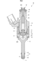
- Fig. 1 shows a fuel injection valve 10 according to an embodiment of the present invention.
- the fuel injection valve 10 of the first embodiment includes a valve housing 13 in which a fuel injection hole 11 and a valve seat 12 are formed, a valve body 15 that enables fuel injection from the fuel injection hole 11 by lifting the valve body 15 from a closed position in contact with the valve seat 12 to an open position in response to excitation of a coil 14, and a return spring 16 that returns the valve body 15 to the closed position in contact with the valve seat 12.
- the lift of the valve body 15 to the open position is achieved by settling the overshoot and overshoot return that occur during the lift.
- the valve body 15 has a rod 18 connected to a valve portion 17 that cooperates with the valve seat 12.
- the rod 18 is formed in a cylindrical shape that extends in the axial direction.
- the sleeve 25 is the connection part with the fuel rail pipe (not shown), and one end (lower end) of the sleeve extends toward the movable core 21.
- the O-ring 30 is for ensuring airtightness with the fuel rail pipe.
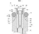
- Figure 2 is a cross-sectional view showing an enlarged view of the other end of the sleeve 25 of the fuel injection valve 10 according to the first embodiment of the present invention.
- the cross-sectional shape of the backup ring 31 is a trapezoid with the bottom side formed on the first opening 25B side being the short side.
- the bottom surface 31A of the backup ring 31 is a flat surface extending in a direction perpendicular to the axial direction of the sleeve 25, and the bottom surface 31A of the backup ring 31 abuts against the perpendicular surface 25F of the outer peripheral surface of the sleeve 25, thereby restricting the movement of the backup ring 31 toward the first opening 25B side.
- the entire inner circumferential surface 31B of the backup ring 31 abuts against the tapered surface 25E of the outer circumferential surface of the sleeve 25, thereby restricting movement of the sleeve 25 in a direction perpendicular to the axial direction.
- the first cylindrical wall 32C extends from the outer peripheral edge of the bottom wall 32B toward the second opening 25C. Therefore, the first cylindrical wall 32C is pressed against the inner peripheral surface of the second opening 25C of the sleeve 25. This limits the movement of the orifice member 32 in the axial direction of the sleeve 25 and in the direction perpendicular to the axial direction of the sleeve 25.
- the backup ring 31 which is a continuous ring with no cuts in the circumferential direction, is more durable than a backup ring that is bias cut, and can improve the reliability of the O-ring 30.
- the backup ring 31 which is a circumferentially continuous ring with no cuts, machining steps for the backup ring such as cutting are not required, and the cost of manufacturing the fuel injection valve 10 can be reduced.
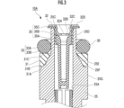
- the engagement wall 35A of the collar member 35 is an annular body (circular ring shape) and has a size that fits the inner circumferential surface of the sleeve 25.
- the inner circumference of the engagement wall 35A, which is an annular body, has a size that fits the outer diameter of the reduced diameter portion 33B of the filter 33.
- the reduced diameter portion 33B of the filter 33 is inserted into the inside of the annular engaging wall 35A, and the engaging wall 35A engages with the outer peripheral edge of the expanded diameter portion 33A of the filter 33 on the first opening 25B side, so that the collar member 35 supports the filter 33.
- the second cylindrical wall 35B extends from the outer peripheral edge of the engagement wall 35A toward the second opening 25C, covering the outer periphery of the enlarged diameter portion 33A of the filter 33 and the outer periphery of the first cylindrical wall 32C of the orifice member 32.
- the second flange 35C protrudes from the other end of the second cylindrical wall 35B in a direction perpendicular to the axial direction of the sleeve 25 beyond the narrow surface 25D (the outer peripheral surface of the other end of the sleeve 25) of the sleeve 25 so as to overlap with the first flange 32D of the orifice member 32.
- the upper surface of the second flange 35C (the surface facing the first flange 32D) and the lower surface of the first flange 32D of the orifice member 32 (the surface facing the second flange 35C) are in close contact with each other.
- a space R is provided between the boundary (corner) between the first flange 32D of the orifice member 32 and the first cylindrical wall 32C, and between the boundary between the second flange 35C of the collar member 35 and the second cylindrical wall 35B, so that the bottom surface of the first flange 32D and the top surface of the second flange 35C are kept in close contact with each other.
- the filter 33, orifice member 32, and collar member 35 are integrated, the filter 33, orifice member 32, and collar member 35 can be attached to the sleeve 25 in the same procedure as the process for attaching a conventional filter to a sleeve. This reduces the initial cost of manufacturing the fuel injection valve 10 of this embodiment.
- the thickness of the entire flange can be increased, thereby improving the rigidity of the entire flange.
- the flange can further improve the effect of preventing the O-ring 30 from coming loose.
- the thickness t1 of the first flange 32D in the axial direction of the sleeve 25 is thicker than the thickness t2 of the second flange 35C, and the thickness t1 of the first flange 32D is 0.3 to 1.0 mm, so that sufficient strength can be ensured to prevent the O-ring 30 from coming loose.
- the thickness t1 of the first flange 32D is less than 0.3 mm, the strength of the first flange 32D tends to be insufficient, and if the thickness t1 exceeds 1.0 mm, press processing becomes difficult, which is not preferable.
- the present invention can provide a fuel injection valve 10 with improved reliability of the O-ring 30.
- Fuel injection valve 25 Sleeve 25A: Fuel path 25B: First opening 25C: Second opening 30: O-ring 31: Backup ring 32: Orifice member 32A: Orifice hole 32B: Bottom wall 32C: First cylindrical wall 32D: First flange 33: Filter 33A: Enlarged diameter portion 33B: Reduced diameter portion 35: Collar member 35A: Engagement wall 35B: Second cylindrical wall 35C: Second flange
Landscapes
- Engineering & Computer Science (AREA)
- Chemical & Material Sciences (AREA)
- Combustion & Propulsion (AREA)
- Mechanical Engineering (AREA)
- General Engineering & Computer Science (AREA)
- Fuel-Injection Apparatus (AREA)
Abstract
Description
筒状のスリーブと、
スリーブの外周に配置されるОリングと、
Оリングを支持するバックアップリングと、
オリフィス部材と、を有しており、
オリフィス部材は、スリーブの内側に配置され且つオリフィス孔を形成した底壁と、該底壁の外周縁部から延出しスリーブの内周に圧接される筒状の第1筒状壁と、該第1筒状壁からスリーブの軸方向と直交する方向に向けてスリーブの外周面よりも突出した第1鍔部とを有しており、
スリーブにオリフィス部材が取付けられた状態で、スリーブの外周面と、バックアップリングと、第1鍔部とによって、Оリングを抜け止め保持するOリング溝が画定される。
以下、図面を用いて本発明の実施形態を説明する。図1は、本発明の一実施形態に係る燃料噴射弁10を示す。
第2実施形態について説明する。なお、本発明の第1実施形態による燃料噴射弁10と同一の構成については適宜説明を省略する。
Claims (4)
- 内部に燃料経路を有し、一端部に第1開口部が形成され、他端部に前記燃料経路に連通する第2開口部が形成された筒状のスリーブと、
前記スリーブの前記他端部の外周に配置されるОリングと、
前記スリーブの、前記Оリングよりも前記一端部寄りの外周に配置されて、前記Оリングを支持するバックアップリングと、
前記スリーブの前記他端部に取付けられるオリフィス部材と、を有しており、
前記オリフィス部材は、前記スリーブの前記第2開口部の内側に配置され且つ前記燃料経路に連通するオリフィス孔を形成した底壁と、該底壁の外周縁部から延出し前記スリーブの前記第2開口部の内周に圧接される筒状の第1筒状壁と、該第1筒状壁から前記スリーブの軸方向と直交する方向に向けて前記スリーブの前記他端部の外周面よりも突出した第1鍔部とを有しており、
前記スリーブの前記他端部に前記オリフィス部材が取付けられた状態で、前記スリーブの前記他端部の外周面と、前記バックアップリングと、前記第1鍔部とによって、前記Оリングを抜け止め保持するOリング溝が画定されることを特徴とする燃料噴射弁。 - 請求項1に記載の燃料噴射弁において、
前記バックアップリングは、切り込みのない周方向に連続した環状をなし、且つ、前記Oリングと接触する平坦な接触面を有する燃料噴射弁。 - 請求項1または2のいずれか一項に記載の燃料噴射弁において、
前記スリーブの前記燃料経路内にはフィルタが挿入され、且つ、前記フィルタはカラー部材で支持されており、
前記フィルタは、前記スリーブの前記第2開口部内に配置される拡径部と、該拡径部から前記スリーブの前記一端部側に向けて延出し前記拡径部よりも縮径した縮径部とを有しており、
前記カラー部材は、前記フィルタの前記拡径部の外周縁部に係合する係合壁と、該係合壁から延出し前記拡径部の外周及び前記オリフィス部材の前記第1筒状壁の外周を覆う筒状の第2筒状壁と、該第2筒状壁から前記スリーブの軸方向と直交する方向に向けて、前記オリフィス部材の前記第1鍔部に重なるように前記スリーブの前記他端部の外周面よりも突出した第2鍔部とを有しており、
前記フィルタの前記拡径部が、前記オリフィス部材の前記底壁と前記カラー部材の前記係合壁とで挟み込まれると共に、前記オリフィス部材の前記第1筒状壁が前記カラー部材の前記第2筒状壁に圧接されて、前記フィルタと前記オリフィス部材と前記カラー部材とが一体化された組立体が構成される燃料噴射弁。 - 請求項3に記載の燃料噴射弁において、
前記スリーブの軸方向における前記第1鍔部の厚さは前記第2鍔部の厚さよりも厚く、且つ、前記第1鍔部の厚さは0.3~1.0mmである燃料噴射弁。
Priority Applications (2)
| Application Number | Priority Date | Filing Date | Title |
|---|---|---|---|
| PCT/JP2023/024368 WO2025004318A1 (ja) | 2023-06-30 | 2023-06-30 | 燃料噴射弁 |
| JP2025529168A JPWO2025004318A1 (ja) | 2023-06-30 | 2023-06-30 |
Applications Claiming Priority (1)
| Application Number | Priority Date | Filing Date | Title |
|---|---|---|---|
| PCT/JP2023/024368 WO2025004318A1 (ja) | 2023-06-30 | 2023-06-30 | 燃料噴射弁 |
Publications (1)
| Publication Number | Publication Date |
|---|---|
| WO2025004318A1 true WO2025004318A1 (ja) | 2025-01-02 |
Family
ID=93938009
Family Applications (1)
| Application Number | Title | Priority Date | Filing Date |
|---|---|---|---|
| PCT/JP2023/024368 Ceased WO2025004318A1 (ja) | 2023-06-30 | 2023-06-30 | 燃料噴射弁 |
Country Status (2)
| Country | Link |
|---|---|
| JP (1) | JPWO2025004318A1 (ja) |
| WO (1) | WO2025004318A1 (ja) |
Citations (6)
| Publication number | Priority date | Publication date | Assignee | Title |
|---|---|---|---|---|
| JPH01138366A (ja) * | 1987-11-23 | 1989-05-31 | Nippon Denso Co Ltd | 内燃機関用電磁式燃料噴射弁 |
| US20020092933A1 (en) * | 2000-09-18 | 2002-07-18 | Siemens Automotive Corporation | Solenoid actuated fuel injector |
| JP2005113815A (ja) * | 2003-10-08 | 2005-04-28 | Keihin Corp | 燃料噴射弁 |
| US20070227984A1 (en) * | 2006-03-31 | 2007-10-04 | Wells Allan R | Injector fuel filter with built-in orifice for flow restriction |
| JP2018155206A (ja) * | 2017-03-20 | 2018-10-04 | 株式会社Soken | 燃料噴射装置、および、燃料噴射システム |
| JP2022102752A (ja) * | 2020-12-25 | 2022-07-07 | 日立Astemo株式会社 | 電磁式燃料噴射弁 |
-
2023
- 2023-06-30 JP JP2025529168A patent/JPWO2025004318A1/ja active Pending
- 2023-06-30 WO PCT/JP2023/024368 patent/WO2025004318A1/ja not_active Ceased
Patent Citations (6)
| Publication number | Priority date | Publication date | Assignee | Title |
|---|---|---|---|---|
| JPH01138366A (ja) * | 1987-11-23 | 1989-05-31 | Nippon Denso Co Ltd | 内燃機関用電磁式燃料噴射弁 |
| US20020092933A1 (en) * | 2000-09-18 | 2002-07-18 | Siemens Automotive Corporation | Solenoid actuated fuel injector |
| JP2005113815A (ja) * | 2003-10-08 | 2005-04-28 | Keihin Corp | 燃料噴射弁 |
| US20070227984A1 (en) * | 2006-03-31 | 2007-10-04 | Wells Allan R | Injector fuel filter with built-in orifice for flow restriction |
| JP2018155206A (ja) * | 2017-03-20 | 2018-10-04 | 株式会社Soken | 燃料噴射装置、および、燃料噴射システム |
| JP2022102752A (ja) * | 2020-12-25 | 2022-07-07 | 日立Astemo株式会社 | 電磁式燃料噴射弁 |
Also Published As
| Publication number | Publication date |
|---|---|
| JPWO2025004318A1 (ja) | 2025-01-02 |
Similar Documents
| Publication | Publication Date | Title |
|---|---|---|
| JP6391814B2 (ja) | 内燃機関のコンプレッサ用のブローオフ弁 | |
| CN101490403B (zh) | 具有压力平衡的控制阀的燃料喷射器 | |
| US20150078922A1 (en) | High pressure pump | |
| US7229064B2 (en) | Valve for controlling a fluid | |
| JP3631413B2 (ja) | 電磁弁及びそれを用いた燃料噴射装置 | |
| US7571891B2 (en) | Solenoid valve | |
| JP5472751B2 (ja) | 高圧ポンプ | |
| CN114502833A (zh) | 燃料供给泵 | |
| JP2024539405A (ja) | 自由ストロークを有するハイドロリック式の減衰装置を備えたガスインジェクタ | |
| EP1512867B1 (en) | A fuel system with integrated fuel injector and common rail and manufacturing method thereof | |
| JP6689178B2 (ja) | 高圧燃料供給ポンプ | |
| US6616073B2 (en) | Fuel injection valve | |
| CN113677919B (zh) | 流量控制阀及其组装方法 | |
| US20030051700A1 (en) | Internal combustion engine fuel injector and relative fabrication method | |
| CN109937297A (zh) | 高压燃料供给泵 | |
| JP2012026421A (ja) | 減圧弁 | |
| JP5529615B2 (ja) | 高圧ポンプ | |
| WO2019012970A1 (ja) | 高圧燃料ポンプ | |
| CN105888887A (zh) | 具有经改善的密封特性的气阀 | |
| JP7284348B2 (ja) | 高圧燃料供給ポンプ | |
| JP2010038109A (ja) | ガス燃料用噴射弁 | |
| KR20180074595A (ko) | 연료 분사 밸브 | |
| JP2008223535A (ja) | 電磁式燃料噴射弁 | |
| WO2018024714A1 (en) | Filter assembly for an injection valve, valve assembly and injection valve | |
| JP4669852B2 (ja) | 電磁式燃料噴射弁 |
Legal Events
| Date | Code | Title | Description |
|---|---|---|---|
| 121 | Ep: the epo has been informed by wipo that ep was designated in this application |
Ref document number: 23943709 Country of ref document: EP Kind code of ref document: A1 |
|
| ENP | Entry into the national phase |
Ref document number: 2025529168 Country of ref document: JP Kind code of ref document: A |
|
| WWE | Wipo information: entry into national phase |
Ref document number: 2025529168 Country of ref document: JP |
|
| NENP | Non-entry into the national phase |
Ref country code: DE |
|
| 122 | Ep: pct application non-entry in european phase |
Ref document number: 23943709 Country of ref document: EP Kind code of ref document: A1 |