WO2025004214A1 - 回転子コア、回転子および電動機 - Google Patents
回転子コア、回転子および電動機 Download PDFInfo
- Publication number
- WO2025004214A1 WO2025004214A1 PCT/JP2023/023944 JP2023023944W WO2025004214A1 WO 2025004214 A1 WO2025004214 A1 WO 2025004214A1 JP 2023023944 W JP2023023944 W JP 2023023944W WO 2025004214 A1 WO2025004214 A1 WO 2025004214A1
- Authority
- WO
- WIPO (PCT)
- Prior art keywords
- rotor core
- magnet
- hole
- magnet slot
- slot
- Prior art date
- Legal status (The legal status is an assumption and is not a legal conclusion. Google has not performed a legal analysis and makes no representation as to the accuracy of the status listed.)
- Ceased
Links
Images




Classifications
-
- H—ELECTRICITY
- H02—GENERATION; CONVERSION OR DISTRIBUTION OF ELECTRIC POWER
- H02K—DYNAMO-ELECTRIC MACHINES
- H02K1/00—Details of the magnetic circuit
- H02K1/06—Details of the magnetic circuit characterised by the shape, form or construction
- H02K1/22—Rotating parts of the magnetic circuit
- H02K1/27—Rotor cores with permanent magnets
- H02K1/2706—Inner rotors
- H02K1/272—Inner rotors the magnetisation axis of the magnets being perpendicular to the rotor axis
- H02K1/274—Inner rotors the magnetisation axis of the magnets being perpendicular to the rotor axis the rotor consisting of two or more circumferentially positioned magnets
- H02K1/2753—Inner rotors the magnetisation axis of the magnets being perpendicular to the rotor axis the rotor consisting of two or more circumferentially positioned magnets the rotor consisting of magnets or groups of magnets arranged with alternating polarity
- H02K1/276—Magnets embedded in the magnetic core, e.g. interior permanent magnets [IPM]
- H02K1/2766—Magnets embedded in the magnetic core, e.g. interior permanent magnets [IPM] having a flux concentration effect
Definitions
- This disclosure relates to a rotor core, a rotor, and an electric motor.
- the end face of the motor's rotor core is formed with multiple pairs of magnet slots arranged in a V-shape, with magnets inserted into each magnet slot. Holes are formed in the rotor core to reduce the weight and inertia of the rotor core (see, for example, Patent No. 6987310). However, if holes are formed inside each pair of magnet slots arranged in a V-shape, the flow of magnetic flux is impeded, reducing torque.
- a rotor core in which a plurality of pairs of magnet slots extending in the axial direction of the rotor core are formed, the plurality of pairs of magnet slots are arranged at equal intervals in the circumferential direction of the rotor core in a radial cross section of the rotor core, each pair of magnet slots of the plurality of pairs of magnet slots includes a first magnet slot inclined counterclockwise with respect to the radius of the rotor core and a second magnet slot inclined clockwise with respect to the radius of the rotor core, and in each pair of magnet slots, one end of the first magnet slot and one end of the second magnet slot are inclined with respect to the radius of the rotor core.
- the rotor core is provided in which the first and second magnet slots are spaced apart from each other, and the other end of the first magnet slot and the other end of the second magnet slot are adjacent to each other radially inward of the rotor core relative to the one end of the first magnet slot and the one end of the second magnet slot, and a first hole is formed adjacent to each pair of magnet slots, and the first hole includes a first portion corresponding to at least a part of the area between the other end of the first magnet slot and the other end of the second magnet slot, and a second portion that is continuous with the first portion and located radially inward of the rotor core relative to the first portion.
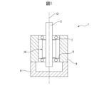
- FIG. 1 is an axial cross-sectional view of an electric motor including a rotor core according to the present disclosure.
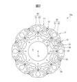
- FIG. 2 is a radial cross-sectional view of a rotor core according to the first embodiment.
- FIG. 3 is a partial cross-sectional view of the rotor core shown in FIG. 2 .
- FIG. 4 is an enlarged partial cross-sectional view of a portion of FIG. 3.
- FIG. 3 is a radial cross-sectional view of a rotor core similar to FIG. 2 .
- FIG. 3 is another partial cross-sectional view of the rotor core shown in FIG. 2 .
- FIG. 7 is an enlarged partial cross-sectional view of a portion of FIG. 6.
- FIG. 1 is a partial cross-sectional view showing magnetic flux of a motor in the prior art.
- FIG. 1 is a diagram showing the relationship between time and torque of a motor in the prior art.
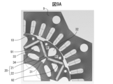
- FIG. 2 is a partial cross-sectional view showing magnetic flux of the electric motor according to the first embodiment.
- FIG. 4 is a diagram showing the relationship between time and torque of an electric motor based on the first embodiment.
- FIG. 1 is a partial cross-sectional view showing the magnetization rate of a motor according to a conventional technique.
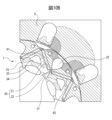
- FIG. 2 is a partial cross-sectional view showing a magnetization rate of the electric motor based on the first embodiment.
- Fig. 1 is an axial cross-sectional view of an electric motor including a rotor core according to the present disclosure.
- electric motor 1 includes a stator 9 and a rotor 10 rotatably supported by stator 9.
- a first bearing 7 and a second bearing 8 are disposed on the inner peripheral surface of stator 9.
- a shaft portion 5 that passes through rotor 9 is rotatably supported by stator 9 through first bearing 7 and second bearing 8.
- a detector 6 that detects the number of rotations of shaft portion 5 and the like is attached to one end of stator 9.
- Figure 2 is a radial cross-sectional view of a rotor core based on the first embodiment.
- the rotor core 10a shown in Figure 2 is generally ring-shaped with a through hole for the shaft portion 5 in the center. However, as described below, it is preferable that the outer peripheral surface of the rotor core 10a is not smooth. Also, the rotor core 10a is usually formed by laminating multiple magnetic plates, such as iron plates, carbon steel plates, and electromagnetic steel plates, in the shape shown in Figure 2, or from a pressed powder iron core.
- the rotor core 10a has multiple pairs of magnet slots 20 formed at equal intervals in the circumferential direction, extending in the axial direction of the rotor core 10a.
- Each pair of magnet slots 20 includes a first magnet slot 21 that is inclined counterclockwise with respect to the radius of the rotor 10, and a second magnet slot 22 that is inclined clockwise with respect to the aforementioned radius of the rotor 10. It is preferable that the absolute values of the inclination angles with respect to the radius of the first magnet slot 21 and the second magnet slot 22 are equal to each other.
- Figure 3 is a partial cross-sectional view of the rotor core shown in Figure 2.
- Permanent magnets 91, 92 are inserted into magnet slots 21, 22 of rotor core 10a, respectively. Therefore, magnet slots 21, 22 are approximately rectangular in shape corresponding to the shapes of permanent magnets 91, 92, and preferably have the same shape as each other. Note that for the purpose of simplicity, illustration of permanent magnets 91, 92 may be omitted.
- Each pair of magnet slots 20 are arranged so as to converge toward each other toward the radial inside of the rotor core 10a.
- the magnet slots 21, 22 are formed to have an approximately V-shape.
- the angle between the magnet slots 21, 22 in each pair of magnet slots 20 is an obtuse angle, for example, 120°. Note that these magnet slots 21, 22 do not need to be connected to each other radially inside the rotor core 10a.
- the outer periphery of the rotor core 10a is composed of a plurality of first outer periphery portions 11 and a plurality of second outer periphery portions 12 that connect the plurality of first outer periphery portions 11.
- the plurality of first outer periphery portions 11 and the plurality of second outer periphery portions 12 are arranged alternately in the circumferential direction of the rotor core 10a.
- each of the plurality of first outer periphery portions 11 roughly corresponds to each region of the plurality of pairs of magnet slots 20.
- each of the first outer periphery portions 11 corresponds to the other end 21x of the magnet slot 21 and the other end 22x of the second magnet slot 22 on the radially inner side of the rotor core 10a.
- the plurality of second outer periphery portions 12 correspond to the regions between two adjacent pairs of magnet slots 20 among the plurality of pairs of magnet slots 20.
- the aa of the second outer periphery portion 12 corresponds to one end 21y of the magnet slot 21 and one end 22y of the second magnet slot 22 on the radially outer side of the rotor core 10a.
- first outer periphery portion 11 is located radially outward of the rotor core 10a relative to the outermost portion of the second outer periphery portion 12.
- a plurality of first outer periphery portions 11 as convex portions and a plurality of second outer periphery portions 12 as concave portions are alternately arranged in the circumferential direction of the rotor core 10a.
- the entire first outer periphery portion 11 is located inside a circle whose radius is the line segment connecting the center O of the rotor core 10a and the outermost portion of the first outer periphery portion 11.
- FIG. 5 which is a radial cross-sectional view of the rotor core similar to FIG. 2, the aforementioned circle is indicated by a dashed line.
- the outer circumference of the rotor core 10a is not a perfect circle, the change in the magnetic flux linkage is small when the electric motor 1 having the rotor core 10a is driven, and as a result, it is possible to prevent the cogging torque and torque ripple from increasing. Therefore, in the first embodiment of the present invention, it is possible to improve the controllability of the electric motor 1 having the rotor core 10a.
- each of the outermost parts of the first outer periphery portion 11 is made up of at least one curve.
- the first outer periphery portion 11 is positioned reliably inside the aforementioned circle and is smooth.
- each of the outermost parts of the second outer periphery portion 12 may be made up of at least one straight line.
- the outermost portion of the first outer periphery portion 11 may be composed of at least one straight line
- the outermost portion of the second outer periphery portion 12 may be composed of at least one curved line.
- both the outermost portion of the first outer periphery portion 11 and the outermost portion of the second outer periphery portion 12 may be composed of at least one straight line
- both the outermost portion of the first outer periphery portion 11 and the outermost portion of the second outer periphery portion 12 may be composed of at least one curved line.
- at least one of the outermost portion of the first outer periphery portion 11 and the outermost portion of the second outer periphery portion 12 may be composed of at least one straight line and at least one curved line.
- the outermost portions of the multiple first outer periphery portions 11 are located radially outward of the rotor core 10a than the outermost portions of the multiple second outer periphery portions 12, so that the outer periphery of the rotor core 10a has a shape different from a perfect circle. Therefore, it will be understood that the same effect as described above can be obtained.
- the first outer periphery portion 11 may be located radially inward of the rotor core 10a relative to the second outer periphery portion 12. Even in such a case, the same effect as described above can be obtained and is included in the scope of the first embodiment.
- a plurality of first holes 31 extending in the axial direction of the rotor core 10a are formed at equal intervals in the circumferential direction on the end face of the rotor core 10a.
- each of the plurality of first holes 31 is formed in a region of the rotor core 10a corresponding to the first outer circumferential portion 11.
- the first holes 31 are formed on one radius of the rotor core 10a between the first magnet slot 21 and the second magnet slot 22 in a pair of magnet slots 20. The shape of the first holes 31 will be described later.
- a plurality of second holes 32 are formed at equal intervals in the circumferential direction on the end face of the rotor core 10a.
- Each of the second holes 32 is formed on one radius as mentioned above. Therefore, the first hole 31 and the second hole 32 are arranged side by side on the same radius of the rotor core 10a. Therefore, as can be seen from FIG. 3, the second hole 32 is formed radially outward of the rotor core 10a than the first hole 31.
- the first hole 31 is formed radially inward of the pair of magnet slots 20 of the rotor core 10a
- the second hole 32 is formed radially outward of the pair of magnet slots 20 of the rotor core 10a. The shape of the second hole 32 will be described later.
- multiple sets of third holes 33 and fourth holes 34 are formed at equal intervals in the circumferential direction of rotor core 10a.
- a set of third holes 33 and fourth holes 34 is formed between two adjacent pairs of magnet slots 20 out of the multiple pairs of magnet slots 20.
- the third holes 33 and fourth holes 34 are arranged side by side on the same radius of rotor core 10a.
- the third holes 33 are formed radially outward of the fourth holes 34 on rotor core 10a. The shapes of the third holes 33 and fourth holes 34 will be described later.
- the first hole 31 is an approximately isosceles triangle with an acute apex angle.
- the apex side of the approximately isosceles triangle is located radially outside the rotor core 10a, and the base side of the approximately isosceles triangle is located radially inside the rotor core 10a.
- the base of the approximately isosceles triangle is perpendicular to one radius of the rotor core 10a.
- the reason for using the term "approximately isosceles triangle" is that it includes cases that differ from a perfect isosceles triangle, such as when the apex of the isosceles triangle is rounded, when each of the two hypotenuses of the isosceles triangle is made up of multiple straight lines, or when each of the two hypotenuses of the isosceles triangle includes a curve.
- FIG. 4 is an enlarged partial cross-sectional view of a portion of FIG. 3.
- the first hole 31 is composed of a first portion 31a including the acute angle of an approximately isosceles triangle, and a second portion 31b including the base of the approximately isosceles triangle.
- the first portion 31a has a shape similar to that of the first hole 31. It is preferable that the boundary line between the first portion 31a and the second portion 31b is parallel to the base.
- the boundary between the first portion 31a and the second portion 31b corresponds to a portion of the line segment L0 that connects the other end 21x of the first magnet slot 21 and the other end 22x of the second magnet slot 22 on the radially inner side of the rotor core 10a.
- the line segment L0 connects a portion of the other end 21x of the first magnet slot 21 located at the radially innermost position of the rotor core 10a and a portion of the other end 22x of the second magnet slot 22 located at the radially innermost position of the rotor core 10a.
- the other end 21x of the first magnet slot 21 and the hypotenuse of the approximately isosceles triangle adjacent thereto are approximately parallel.
- the other end 22x of the first magnet slot 22 and the hypotenuse of the approximately isosceles triangle adjacent thereto are approximately parallel.
- the first hole 31 in the present disclosure is formed adjacent to the region between the first magnet slot 21 and the first magnet slot 22.
- the first portion 31a of the first hole 31 is formed between the other end 21x of the first magnet slot 21 and the other end 22x of the second magnet slot 22.
- the second portion 31b of the first hole 31 is formed radially inward of the rotor core 10a than the first portion 31a.
- the first hole 31 according to the present disclosure necessarily includes the second portion 31b in addition to the first portion 31a formed between the first magnet slot 21 and the second magnet slot 22. Therefore, in the present disclosure, a large first hole 31 can be formed. As a result, the rotor core 10a can be made lighter, and the speed of the electric motor 1 can be increased.
- a gap 21g is formed on one end 21y side of the first magnet slot 21.
- the gap 21g is formed so as to partially protrude from the one end 21y along the length of the first magnet slot 21.
- a gap 22g of a similar shape is formed on one end 22y side of the second magnet slot 22.
- a gap 21p is formed on the other end 21x side of the first magnet slot 21.
- a gap 22p is formed on the other end 22x side of the second magnet slot 22. The gaps 21p, 22p protrude partially from the other ends 21x, 22x along the length portions of the first magnet slot 21 and the second magnet slot 22.
- gaps 21g, 21p of the first magnet slot 21 and 22g, 22p of the second magnet slot 22 act as flux barriers that suppress magnetic flux leakage from both longitudinal ends of the magnets 91, 92 to the rotor core.
- the gaps 21g, 22g, 21p, 22p also serve to easily insert/remove the permanent magnets 91, 92 into/from the corresponding magnet slots 21, 22.
- the rotor core 10a is made lighter by forming the aforementioned gaps 21g, 21p, 22g, 22p.
- a line segment L0' is shown connecting a portion of the other end 21x of the first magnet slot 21 on the radial outside of the rotor core 10a and a portion of the other end 22x of the second magnet slot 22 on the radial outside of the rotor core 10a.
- a portion of the gaps 21p, 22p each protrudes beyond the line segment L0' radially outward of the rotor core 10a.
- the gaps 21p, 22p are formed so as to protrude from the other ends 21x, 22x in both a direction perpendicular to the length portions of the first magnet slot 21 and the second magnet slot 22 and in the length direction of the magnet slots 21, 22.
- the gaps 21p, 22p are connected to the first magnet slot 21 and the second magnet slot 22, respectively. Also, as can be seen from the figure, the gaps 21p, 22p are not connected to each other.
- the shortest distance between the gap 21p at the other end 21x of the first magnet slot 21 and the first hole 31 is distance a.
- the shortest distance between the gap 22p at the other end 22x of the second magnet slot 22 and the first hole 31 is also distance a.
- the shortest distance between the other end 21x of the first magnet slot 21 and the first hole 31 is distance a'.
- the shortest distance between the other end 22x of the second magnet slot 22 and the first hole 31 is also distance a'.
- distance a can be half or less of distance a', preferably 1/4 or less. In a typical example, these distances a are greater than 0 and less than 1 millimeter.
- the angle between the magnet slots 21, 22 is an obtuse angle, and in such a case, it is difficult for the electric motor 1 equipped with the rotor core 10a to output high torque.
- the rotor core 10a in this disclosure is formed with the first hole 31 and gaps 21p, 22p of the shape and dimensions described above. This reduces magnetic flux leakage when the electric motor 1 is running, and therefore the torque of the electric motor 1 can be maintained high even when the angle between the magnet slots 21, 22 is an obtuse angle. Furthermore, by forming the first hole 31 and gaps 21p, 22p, the weight of the rotor core 10a can be reduced.
- the rotor 10 with magnets 91, 92 inserted into all magnet slots 21, 22 is placed in the inner cylinder of the magnetizing yoke (not shown). At this time, the portions of magnets 91, 92 located radially inside the rotor 10 are far from the magnetizing yoke. For this reason, it becomes difficult to sufficiently magnetize the aforementioned portions of magnets 91, 92, particularly when the angle between the first magnet slot 21 and the second magnet slot 22 is acute.
- the angle between the magnet slots 21, 22 is an obtuse angle, so the other ends 21x, 22x of the magnet slots 21, 22 are located relatively close to the outer circumferential surface of the rotor core 10a. Therefore, in the present disclosure, it is relatively easy to magnetize even a portion of the magnets 91, 92 located near the other ends 21x, 22x of the magnet slots 21, 22. In other words, in the present disclosure, the angle between the magnet slots 21, 22 can be made an obtuse angle, which has the additional effect of making it easier to magnetize the magnets. This will be described later with reference to Figures 10A and 10B.
- the first hole 31 and the second hole 32 are arranged side by side on the same radius of the rotor core 10a.
- the first hole 31 is formed radially inward of the pair of magnet slots 20 of the rotor core 10a
- the second hole 32 is formed radially outward of the pair of magnet slots 20 of the rotor core 10a.
- the second hole 32 is composed of a first portion 32a and a second portion 32b located radially outward of the rotor core 10a relative to the first portion 32a. It is preferable that the boundary line between the first portion 32a and the second portion 32b of the second hole 32 is parallel to the base of the approximately isosceles triangle of the first hole 31.
- the first portion 32a is in the shape of an approximately isosceles triangle with its apex angle pointing toward the center O of the rotor core 10a.
- the apex angle of the approximately isosceles triangle of the first portion 32a is an acute angle, and is preferably larger than the apex angle of the approximately isosceles triangle of the first portion 31a of the first hole 31.
- the second portion 32b is in the shape of an arc, for example a semicircular arc, protruding from the base of the isosceles triangle toward the outside in the radial direction of the rotor core 10a. It is preferable that the first portion 32a and the second portion 32b are smoothly connected to each other.
- the hypotenuse of the approximately isosceles triangle of the first portion 32a and the tangent of the second portion 32b are equal to each other.
- the arc of the second portion 32b may be longer or shorter than the arc of the semicircle.
- the arc of the second portion 32b may also be an elliptical arc.
- the line segment connecting one end 21y of the first magnet slot 21 and one end 22y of the second magnet slot 22 on the radially outer side of the rotor core 10a is defined as the first line segment L1.
- the first line segment L1 connects a portion of one end 21y of the first magnet slot 21 located at the radially outermost position of the rotor core 10a to a portion of one end 22y of the second magnet slot 22 located at the radially outermost position of the rotor core 10a.
- the boundary line B1 between the first portion 32a and the second portion 32b of the second hole 32 is preferably parallel to the first line segment L1 and located radially inward of the rotor core 10a with respect to the first line segment L1.
- the second portion 32b of the second hole 32 is located radially outward of the rotor core 10a relative to the first line segment L1. Therefore, in the present disclosure, a large second hole 32 can be formed, which results in a reduction in the weight of the rotor core 10a and an increase in the speed of the electric motor 1. Furthermore, because the second portion 32b is an arc, the flow of magnetic flux is not impeded when the electric motor 1 having the rotor core 10a is in operation. Note that, in order to increase the area of the second hole 32, the boundary line B1 may be on the first line segment L1, or the boundary line B1 may be located radially outward of the rotor core 10a relative to the first line segment L1.
- the first outer circumferential portion 11 in which the second holes 32 are formed protrudes radially outward of the rotor core 10a further than the second outer circumferential portion 12.
- the second holes 32 can be formed further radially outward of the rotor core 10a by the protruding portion of the first outer circumferential portion 11. Therefore, it can be seen that the second holes 32 can be made larger, and the rotor core 10a can be made lighter accordingly.
- the shortest distance between the gap 21p at the other end 21x of the first magnet slot 21 and the second hole 32 is distance b.
- the shortest distance between the gap 22p at the other end 22x of the second magnet slot 22 and the second hole 32 is also distance b. These distances b are measured from a portion of the gaps 21p, 22p that protrude radially outward of the rotor core 10a beyond the line segment L0' to the second hole 32.
- These distances b can also be less than half of the distance a', and preferably less than 1/4. In a typical example, these distances a are greater than 0 and less than 1 millimeter. This makes it possible to obtain the same effect as described above.
- Figure 6 is another partial cross-sectional view of the rotor core shown in Figure 2.
- one pair of magnet slots 20a includes a first magnet slot 21a and a second magnet slot 22a.
- the other pair of magnet slots 20b includes a first magnet slot 21b and a second magnet slot 22b.
- the third hole 33 is formed between the second magnet slot 22a of magnet slot 20a and the first magnet slot 21b of magnet slot 20b.
- the third hole 33 includes an approximately isosceles triangle, for example an obtuse isosceles triangle, whose apex angle 33a is defined by a circular arc.
- the apex angle 33a of the approximately isosceles triangle of the third hole 33 faces radially outward of the rotor core 10a.
- the two hypotenuses of the approximately isosceles triangle of the third hole 33 are parallel to the second magnet slot 22a and the first magnet slot 21b, respectively.
- the portions of the third hole 33 that correspond to the two diagonals of the approximately isosceles triangle may be omitted, and the hypotenuse and base may be connected near the base.
- the portions that correspond to the diagonals are configured with right angles.
- the portions that correspond to the diagonals may be configured with circular arcs.
- a protrusion 33b may be formed from the base of the approximately isosceles triangle of the third hole 33, protruding radially inwardly of the rotor. It is preferable that the protrusion 33b is formed approximately in the center of the base of the approximately isosceles triangle.
- FIG. 7 is a partial cross-sectional view of an enlarged portion of FIG. 6.
- FIG. 7 mainly shows the second magnet slot 22a in one pair of magnet slots 20a and the first magnet slot 21b in the other pair of magnet slots 20b.
- the line segment connecting the other end 22x of the second magnet slot 22a and the other end 21x of the first magnet slot 21b on the radially inner side of the rotor core 10a is called the second line segment L2.
- the second line segment L2 connects a part of the other end 22x of the second magnet slot 22a located at the radially innermost position of the rotor core 10a and a part of the other end 22y of the first magnet slot 21b located at the radially innermost position of the rotor core 10a.
- the third hole 33 is entirely located radially outward of the rotor core 10a from the second line segment L2.
- the third hole 33 is formed in an area surrounded by the second magnet slot 22a in one pair of magnet slots 20a, the first magnet slot 21b in the other pair of magnet slots 20b, and the second line segment L2. In other words, the third hole 33 is not formed on or in the vicinity of the second line segment L2. This ensures the strength of the rotor core 10a. Furthermore, it can be seen that the flow of magnetic flux is not impeded when the electric motor 1 including the rotor core 10a is driven.
- the third hole 33 is formed between the second magnet slot 22a of one pair of magnet slots 20a and the first magnet slot 21b of the other pair of magnet slots 20b. And, the shortest distance between the third hole 33 and the first magnet slot 21b is greater than the shortest distance c between the third hole 33 and the second magnet slot 22a.
- the shortest distance c is preferably at least half the thickness t of magnets 91, 92. In a typical example, the shortest distance is at least 2 millimeters.
- third hole 33 is located at a distance from magnets 91, 92 that is at least half the thickness t of magnets 91, 92, the magnetization described above can be performed without being affected by third hole 33.
- a line segment connecting one end 22y of the second magnet slot 22a and one end 21y of the first magnet slot 21b on the radially inner side of the rotor core 10a is defined as a third line segment L3.
- the third line segment L3 connects a portion of one end 21y of the first magnet slot 22a located at the radially innermost position of the rotor core 10a and a portion of one end 22y of the second magnet slot 21b located at the radially innermost position of the rotor core 10a.
- the third line segment L3 and the second line segment L2 are parallel to each other.
- the third hole 33 has a dimension d on the center line between the second magnet slot 22a and the first magnet slot 21b, which corresponds to the radius of the rotor core 10a.
- Dimension d does not necessarily have to be on the center line of the third hole 33.
- the dimension between the second line segment L2 and the third line segment L3 is dimension e. In such a case, it is preferable that dimension e is at least twice dimension d.
- the reason for giving the third hole 33 this shape and arrangement is to ensure the strength of the area between the third hole 33 and the second magnet slot 22a and the first magnet slot 21b, as well as to smooth the flow of magnetic flux. Furthermore, in a motor 1 equipped with such a rotor core 10a, it is possible to reduce inertia.
- the fourth hole 34 will be described. As can be seen from FIG. 7, the third hole 33 and the fourth hole 34 are juxtaposed on a radius of the rotor core 10a that passes through the center between the second magnet slot 22a of one pair of magnet slots 20a and the first magnet slot 21b of the other pair of magnet slots 20b. A set consisting of the third hole 33 and the fourth hole 34 is formed between two adjacent pairs of magnet slots 20a, 20b among the multiple pairs of magnet slots 20.
- the third hole 33 and the fourth hole 34 may each be formed line-symmetrically with respect to the aforementioned radius.
- the fourth hole 34 is formed radially inward of the rotor core 10a from the second line segment L2.
- the fourth hole 34 has a substantially oval or elliptical shape, and its major axis is parallel to the line segment L2. Furthermore, it is preferable that the fourth hole 34 has protrusions 34a, 34b extending along the aforementioned radius. As shown in FIG. 7, the protrusion 34a extends radially outward from the rotor core 10a, and the protrusion 34b extends radially inward from the rotor core 10a. By forming these protrusions 34a, 34b, the fourth hole 34 can be enlarged, and as a result, the rotor core 10a can be made lighter. Note that one of the protrusions 34a and 34b may be omitted.
- FIG. 8A is a partial cross-sectional view showing the magnetic flux of an electric motor in the prior art
- FIG. 9A is a partial cross-sectional view showing the magnetic flux of an electric motor equipped with a rotor core based on the first embodiment.
- the electric motor 1' shown in FIG. 8A includes a stator 9' and a rotor 10'.
- the first hole 31 to the fourth hole 34 are not formed in the rotor 10'.
- the electric motor 1 shown in FIG. 9A includes a stator 9 and the rotor 10 described above.
- the structures of the rotors 10 and 10' are well known, so a description thereof will be omitted.
- the angle between the first magnet slot 21' and the second magnet slot 22' of the pair of magnet slots 20' in FIG. 8A is an acute angle, for example, 60°. Therefore, the number of magnets 91', 92' inserted into the first magnet slot 21' and the second magnet slot 22', respectively, is greater than the number of magnets 91, 92 shown in FIG. 9A.
- the diameter of the rotor 10' shown in FIG. 8A is equal to the diameter of the rotor 10 shown in FIG. 9A.
- the width W0 of the magnets 91', 92' shown in FIG. 8A is, for example, 31.4 mm
- the width W1 of the magnets 91, 92 shown in FIG. 9A is, for example, 22.5 mm.
- the present disclosure allows the number of magnets 91, 92 to be reduced as compared to the prior art, and allows the dimensions of the magnets 91, 92 to be reduced.
- the electric motor 1 can be significantly lighter than the electric motor 1'.
- the total weight of the magnets 91, 92 of the electric motor 1 can be, for example, approximately 28% less than the total weight of the magnets 91', 92' of the electric motor 1'.
- FIG. 8B is a diagram showing the relationship between time and torque in a motor of the prior art
- FIG. 9B is a diagram showing the relationship between time and torque in the motor of the first embodiment.
- the horizontal axis indicates time
- the vertical axis indicates the torque of motors 1 and 1'.
- the maximum torque value of motor 1' is between 100 Nm and 101 Nm.
- the maximum torque value of motor 1 is between 91.5 Nm and 92 Nm. In other words, even when first hole 31 to fourth hole 34 are formed, the decrease in torque is suppressed to less than 10%.
- FIG. 10A is a partial cross-sectional view showing the magnetization rate of an electric motor in the prior art
- FIG. 10B is a partial cross-sectional view showing the magnetization rate of an electric motor in the first embodiment.
- three stages of magnetization rate are shown, and the higher the magnetization rate, the darker the area of the magnetization rate is. Specifically, areas with low magnetization rate (magnetic flux density of 0.0T to 1.7T) are shown in white, areas with medium magnetization rate (magnetic flux density of 2.2T to 3.3T) are shown in light colors, and areas with high magnetization rate (magnetic flux density of 3.5T to 5.0T) are shown in dark colors.
- the magnetization rate of the magnets 91', 92' is about 30%.
- the magnets 91, 92 are magnetized over almost their entirety, and the magnetization rate of the magnets 91, 92 is approximately 100%.
- the magnets 91, 92 can be sufficiently magnetized up to the other end radially inside the rotor 10. Therefore, in this disclosure, in which the angle between the first magnet slot 21 and the second magnet slot 22 is an obtuse angle, magnetization of the magnets 91, 92 can be reliably performed.
- the first hole 31 and the gaps 21p, 22p are formed, and the second hole 32 to the fourth hole 34 do not have to be formed.
- the scope of the present disclosure also includes a configuration in which, in addition to the first hole 33 and the gaps 21p, 22p, at least one of the second hole 32 to the fourth hole 34 is formed.
- the rotor 10 can be made lighter, and inertia can be reduced while magnetizing sufficiently without a significant decrease in torque.
- a rotor core (10a) is formed with a plurality of pairs of magnet slots (20) extending in the axial direction of the rotor core (10a), The plurality of pairs of magnet slots (20) are disposed at equal intervals in a circumferential direction of the rotor core (10a) in a radial cross section of the rotor core (10a),
- Each pair of magnet slots (20) of the plurality of pairs of magnet slots (20) includes a first magnet slot (21) inclined counterclockwise with respect to a radius of the rotor core (10a) and a second magnet slot (22) inclined clockwise with respect to the radius of the rotor core (10a);
- one end of the first magnet slot (21) and one end of the second magnet slot (22) are spaced apart from each other, and the other end of the first magnet slot (21) and the other end of the second magnet slot (22) are adjacent to each other radially
- a gap (21p, 22p) is formed at the other end of the first magnet slot (21) and the other end of the second magnet slot (22), A rotor core (10a) as described in Appendix 1, wherein the gaps (21p, 22p) partially protrude radially outward from the rotor core (10a) beyond a line segment (L0') connecting the other end of the first magnet slot (21) at the radial outside of the rotor core (10a) and the other end of the second magnet slot (22) at the radial outside of the rotor core (10a).
- a distance (a) between the gap (21p) formed at the other end of the first magnet slot (21) and the first hole (31) is equal to or less than half of a distance (a') between the other end of the first magnet slot (21) and the first hole (31);
- the outer periphery of the rotor core (10a) is composed of a plurality of first outer periphery portions (11) and a plurality of second outer periphery portions (12) connecting the first outer periphery portions (11),
- the first outer circumferential portions (11) correspond to respective regions of the pairs of magnet slots (20),
- the second outer circumferential portions (112) each correspond to a region between two adjacent pairs of magnet slots (20a, 20b) among the plurality of pairs of magnet slots (20);
- a rotor core (10a) according to any one of appendix 1 to 3, wherein an outermost portion of the plurality of first outer peripheral portions (11) is located radially outward of the rotor core (10a) relative to an outermost portion of the plurality of second outer peripheral portions (12).
- each of the second holes (32) is formed in a radial cross section of the rotor core (10a) by a substantially isosceles triangle whose apex angle (32a) faces the center of the rotor core (10a) and a circular arc protruding from a base of the isosceles triangle toward the radial outside of the rotor core (10a);
- a distance (b) between the gap (21p) formed at the other end of the first magnet slot (21) and the second hole (32) is equal to or less than half the distance (a') between the other end of the first magnet slot (21) and the first hole (31);
- a third hole (33) is formed between two adjacent pairs of magnet slots (20a, 20b) among the plurality of pairs of magnet slots (20);
- (Appendix 10) A rotor core (10a) according to any one of appendixes 1 to 9, wherein a distance (c) between the third hole (33) and the first magnet slot (21) or the second magnet slot (22) is equal to or greater than half the thickness (t) of a magnet to be inserted into the first magnet slot (21) or the second magnet slot (22).
- (Appendix 11) A rotor core (10a) according to any one of Appendices 1 to 10, wherein a distance (e) between a third line segment (L3) connecting one end of the second magnet slot (22a) in one pair of magnet slots (20a) of the two pairs of magnet slots (20a, 20b) to one end of the first magnet slot (21b) in the other pair of magnet slots (20b) of the two pairs of magnet slots (20a, 20b) and the second line segment (L2) is equal to or greater than twice the length (d) of the third hole (33) in the radial direction of the rotor core (10a).
- a fourth hole (34) is formed radially inward of the rotor core (10a) relative to the third hole (33), A rotor core (10a) according to any one of appendixes 1 to 11, wherein each of the third holes (33) and each of the fourth holes (34) are juxtaposed in the radial direction of the rotor core (10a).
- the electric motor (1) comprises a stator (9) disposed around the rotor (10).
Landscapes
- Engineering & Computer Science (AREA)
- Power Engineering (AREA)
- Permanent Field Magnets Of Synchronous Machinery (AREA)
Priority Applications (4)
| Application Number | Priority Date | Filing Date | Title |
|---|---|---|---|
| CN202380099490.2A CN121532929A (zh) | 2023-06-28 | 2023-06-28 | 转子芯、转子以及电动机 |
| DE112023006059.2T DE112023006059T5 (de) | 2023-06-28 | 2023-06-28 | Rotorkern, rotor und elektromotor |
| JP2025529077A JPWO2025004214A1 (https=) | 2023-06-28 | 2023-06-28 | |
| PCT/JP2023/023944 WO2025004214A1 (ja) | 2023-06-28 | 2023-06-28 | 回転子コア、回転子および電動機 |
Applications Claiming Priority (1)
| Application Number | Priority Date | Filing Date | Title |
|---|---|---|---|
| PCT/JP2023/023944 WO2025004214A1 (ja) | 2023-06-28 | 2023-06-28 | 回転子コア、回転子および電動機 |
Publications (1)
| Publication Number | Publication Date |
|---|---|
| WO2025004214A1 true WO2025004214A1 (ja) | 2025-01-02 |
Family
ID=93937837
Family Applications (1)
| Application Number | Title | Priority Date | Filing Date |
|---|---|---|---|
| PCT/JP2023/023944 Ceased WO2025004214A1 (ja) | 2023-06-28 | 2023-06-28 | 回転子コア、回転子および電動機 |
Country Status (4)
| Country | Link |
|---|---|
| JP (1) | JPWO2025004214A1 (https=) |
| CN (1) | CN121532929A (https=) |
| DE (1) | DE112023006059T5 (https=) |
| WO (1) | WO2025004214A1 (https=) |
Citations (14)
| Publication number | Priority date | Publication date | Assignee | Title |
|---|---|---|---|---|
| JP2000060038A (ja) * | 1998-08-05 | 2000-02-25 | Toyota Motor Corp | 電動機 |
| JP2001211582A (ja) * | 2000-01-26 | 2001-08-03 | Fujitsu General Ltd | 永久磁石電動機 |
| JP2007089291A (ja) * | 2005-09-21 | 2007-04-05 | Toyota Motor Corp | 永久磁石式回転電機 |
| JP2012075278A (ja) * | 2010-09-29 | 2012-04-12 | Aisin Aw Co Ltd | 回転電機のロータ |
| JP2013027100A (ja) * | 2011-07-19 | 2013-02-04 | Aisin Aw Co Ltd | 回転電機 |
| JP2015047009A (ja) * | 2013-08-28 | 2015-03-12 | 株式会社安川電機 | 回転電機 |
| JP2015053822A (ja) * | 2013-09-09 | 2015-03-19 | トヨタ自動車株式会社 | ロータ、および、ロータの製造方法 |
| JP2019186973A (ja) * | 2018-03-30 | 2019-10-24 | アイチエレック株式会社 | 永久磁石電動機 |
| JP2020068533A (ja) * | 2018-10-19 | 2020-04-30 | 本田技研工業株式会社 | ロータ |
| JP2020188594A (ja) * | 2019-05-15 | 2020-11-19 | 日立ジョンソンコントロールズ空調株式会社 | 永久磁石式回転電機及びそれを用いた圧縮機 |
| JP6848135B1 (ja) * | 2020-09-18 | 2021-03-24 | 株式会社東芝 | ロータ |
| JP2021136785A (ja) * | 2020-02-27 | 2021-09-13 | 本田技研工業株式会社 | 回転電機のロータおよび回転電機 |
| JP6987310B1 (ja) * | 2020-04-07 | 2021-12-22 | 三菱電機株式会社 | 回転電機 |
| WO2023053285A1 (ja) * | 2021-09-29 | 2023-04-06 | 株式会社 東芝 | 回転電機の回転子 |
-
2023
- 2023-06-28 WO PCT/JP2023/023944 patent/WO2025004214A1/ja not_active Ceased
- 2023-06-28 DE DE112023006059.2T patent/DE112023006059T5/de active Pending
- 2023-06-28 CN CN202380099490.2A patent/CN121532929A/zh active Pending
- 2023-06-28 JP JP2025529077A patent/JPWO2025004214A1/ja active Pending
Patent Citations (14)
| Publication number | Priority date | Publication date | Assignee | Title |
|---|---|---|---|---|
| JP2000060038A (ja) * | 1998-08-05 | 2000-02-25 | Toyota Motor Corp | 電動機 |
| JP2001211582A (ja) * | 2000-01-26 | 2001-08-03 | Fujitsu General Ltd | 永久磁石電動機 |
| JP2007089291A (ja) * | 2005-09-21 | 2007-04-05 | Toyota Motor Corp | 永久磁石式回転電機 |
| JP2012075278A (ja) * | 2010-09-29 | 2012-04-12 | Aisin Aw Co Ltd | 回転電機のロータ |
| JP2013027100A (ja) * | 2011-07-19 | 2013-02-04 | Aisin Aw Co Ltd | 回転電機 |
| JP2015047009A (ja) * | 2013-08-28 | 2015-03-12 | 株式会社安川電機 | 回転電機 |
| JP2015053822A (ja) * | 2013-09-09 | 2015-03-19 | トヨタ自動車株式会社 | ロータ、および、ロータの製造方法 |
| JP2019186973A (ja) * | 2018-03-30 | 2019-10-24 | アイチエレック株式会社 | 永久磁石電動機 |
| JP2020068533A (ja) * | 2018-10-19 | 2020-04-30 | 本田技研工業株式会社 | ロータ |
| JP2020188594A (ja) * | 2019-05-15 | 2020-11-19 | 日立ジョンソンコントロールズ空調株式会社 | 永久磁石式回転電機及びそれを用いた圧縮機 |
| JP2021136785A (ja) * | 2020-02-27 | 2021-09-13 | 本田技研工業株式会社 | 回転電機のロータおよび回転電機 |
| JP6987310B1 (ja) * | 2020-04-07 | 2021-12-22 | 三菱電機株式会社 | 回転電機 |
| JP6848135B1 (ja) * | 2020-09-18 | 2021-03-24 | 株式会社東芝 | ロータ |
| WO2023053285A1 (ja) * | 2021-09-29 | 2023-04-06 | 株式会社 東芝 | 回転電機の回転子 |
Also Published As
| Publication number | Publication date |
|---|---|
| DE112023006059T5 (de) | 2026-02-26 |
| JPWO2025004214A1 (https=) | 2025-01-02 |
| CN121532929A (zh) | 2026-02-13 |
Similar Documents
| Publication | Publication Date | Title |
|---|---|---|
| US8405270B2 (en) | Permanent magnet buried type electric motor | |
| US8487495B2 (en) | Rotor for motor | |
| JP6806352B2 (ja) | 回転電機、回転子鉄心の製造方法 | |
| JP5310872B2 (ja) | ロータ | |
| JP5250692B2 (ja) | 永久磁石式回転電機 | |
| JP5301868B2 (ja) | 埋込磁石型モータ | |
| JP6191370B2 (ja) | 同期電動機 | |
| JP5574178B2 (ja) | 回転電機のロータ | |
| JP2009273304A (ja) | 回転電機のロータ及び回転電機 | |
| JP6601169B2 (ja) | 回転電機 | |
| JP6390647B2 (ja) | 永久磁石式回転電機 | |
| WO2018066647A1 (ja) | 同期リラクタンス型回転電機 | |
| WO2025004214A1 (ja) | 回転子コア、回転子および電動機 | |
| US11863019B2 (en) | Rotor lamination, rotor laminated core, rotor, electric machine, and vehicle | |
| WO2019234866A1 (ja) | ロータ及びモータ | |
| JP6856011B2 (ja) | 回転電機のロータ | |
| JP2023102517A (ja) | ロータ及び回転電機 | |
| JPWO2020054029A1 (ja) | かご形回転子および回転電機 | |
| JP7832325B2 (ja) | 回転子コア、回転子、および電動機 | |
| JP7851280B2 (ja) | 回転電機 | |
| WO2024224777A1 (ja) | ロータ | |
| WO2024224773A1 (ja) | ロータ | |
| WO2024224774A1 (ja) | ロータ | |
| WO2024224775A1 (ja) | ロータ | |
| JP2008220143A (ja) | 回転電機のロータ及び回転電機 |
Legal Events
| Date | Code | Title | Description |
|---|---|---|---|
| 121 | Ep: the epo has been informed by wipo that ep was designated in this application |
Ref document number: 23943612 Country of ref document: EP Kind code of ref document: A1 |
|
| ENP | Entry into the national phase |
Ref document number: 2025529077 Country of ref document: JP Kind code of ref document: A |
|
| WWE | Wipo information: entry into national phase |
Ref document number: 2025529077 Country of ref document: JP |
|
| WWE | Wipo information: entry into national phase |
Ref document number: 112023006059 Country of ref document: DE |
|
| WWP | Wipo information: published in national office |
Ref document number: 112023006059 Country of ref document: DE |