WO2024262484A1 - アフターシールドガス治具、溶接装置、溶接設備、溶接方法および円筒構造物の製造方法 - Google Patents
アフターシールドガス治具、溶接装置、溶接設備、溶接方法および円筒構造物の製造方法 Download PDFInfo
- Publication number
- WO2024262484A1 WO2024262484A1 PCT/JP2024/022005 JP2024022005W WO2024262484A1 WO 2024262484 A1 WO2024262484 A1 WO 2024262484A1 JP 2024022005 W JP2024022005 W JP 2024022005W WO 2024262484 A1 WO2024262484 A1 WO 2024262484A1
- Authority
- WO
- WIPO (PCT)
- Prior art keywords
- workpiece
- welding
- welding torch
- shielding
- shield gas
- Prior art date
- Legal status (The legal status is an assumption and is not a legal conclusion. Google has not performed a legal analysis and makes no representation as to the accuracy of the status listed.)
- Ceased
Links
Images


Classifications
-
- B—PERFORMING OPERATIONS; TRANSPORTING
- B23—MACHINE TOOLS; METAL-WORKING NOT OTHERWISE PROVIDED FOR
- B23K—SOLDERING OR UNSOLDERING; WELDING; CLADDING OR PLATING BY SOLDERING OR WELDING; CUTTING BY APPLYING HEAT LOCALLY, e.g. FLAME CUTTING; WORKING BY LASER BEAM
- B23K9/00—Arc welding or cutting
- B23K9/24—Features related to electrodes
- B23K9/28—Supporting devices for electrodes
- B23K9/29—Supporting devices adapted for making use of shielding means
Definitions
- This disclosure relates to an after-shield gas fixture, a welding device, a welding facility, a welding method, and a method for manufacturing a cylindrical structure.
- the after-shield gas fixture that supplies the after-shield gas has a shielding part.
- the shielding part prevents the diffusion of the after-shield gas (see, for example, JP 2022-149068 A).
- This disclosure has been made to solve the problems described above, and the purpose of this disclosure is to provide a welding device that suppresses the diffusion of after-shielding gas.
- the after-shield gas fixture includes a gas supply unit.
- the gas supply unit has an exhaust unit. After-shield gas can be blown out from the exhaust unit toward the workpiece.
- the gas supply unit has a shielding unit and a first maintenance mechanism unit. When viewed from the direction in which the after-shield gas is blown out, the shielding unit is disposed so as to surround the exhaust unit.
- the first maintenance mechanism unit can maintain a constant distance between the shielding unit and the workpiece, independent of the position of the welding torch.
- a welding apparatus includes a welding torch and an after-shield gas fixture.
- a welding facility includes a welding device, a holding mechanism, and a rotating mechanism.
- the holding mechanism holds a workpiece.
- the rotating mechanism rotates the workpiece.
- the welding method includes a step of moving a workpiece near a welding device, and a step of welding the workpiece.
- the moving step the workpiece is moved so as to come into contact with a first maintenance mechanism.
- a welding torch generates an arc toward the workpiece.
- after-shield gas is blown from a gas supply unit toward the workpiece.
- the first maintenance mechanism maintains a constant distance between the shielding part and the workpiece.
- the second maintenance mechanism maintains a constant distance between the welding torch and the workpiece.
- the welding method includes a step of moving a workpiece near a welding device, and a step of welding the workpiece.
- the moving step the workpiece is moved so as to come into contact with a first maintenance mechanism.
- a welding torch generates an arc toward the workpiece.
- aftershield gas is blown from a gas supply unit toward the workpiece.
- the first maintenance mechanism maintains a constant distance between the shielding unit and the workpiece.
- the drive unit adjusts the distance between the welding torch and the workpiece.
- the method for manufacturing a cylindrical structure according to the present disclosure is a method for manufacturing a cylindrical structure using the above-mentioned welding method.
- the workpiece is a body portion and a pair of end portions that constitute the cylindrical structure.
- FIG. 1 is a perspective view of a welding device according to a first embodiment.
- 2 is a schematic cross-sectional view of the gas supply unit taken along line II-II in FIG. 1.
- 1 is a schematic cross-sectional view of a welding device according to a first embodiment.
- 10 is a schematic cross-sectional view showing a modified example of the gas supply unit in the welding device according to the first embodiment.
- FIG. 10 is a schematic cross-sectional view showing a modified example of the gas supply unit in the welding device according to the first embodiment.
- FIG. 10 is a schematic cross-sectional view showing a modified example of the gas supply unit in the welding device according to the first embodiment.
- FIG. 10 is a schematic cross-sectional view showing a modified example of the gas supply unit in the welding device according to the first embodiment.
- FIG. 13 is a side view showing a modified example of the side shielding portion in the welding device according to the first embodiment.
- FIG. 13 is a side view showing a modified example of the side shielding portion in the welding device according to the first embodiment.
- FIG. 2 is a side view showing the positional relationship between a side shield and a welding torch in the welding device according to the first embodiment.
- FIG. 13 is a side view showing a modified example of the first maintenance mechanism in the welding device according to the first embodiment.
- FIG. 13 is a side view showing a modified example of the first maintenance mechanism in the welding device according to the first embodiment.
- FIG. 13 is a front view showing a modified example of the first maintenance mechanism in the welding device according to the first embodiment.
- FIG. 13 is a side view showing a modified example of the side shielding portion in the welding device according to the first embodiment.
- FIG. 13 is a side view showing a modified example of the side shielding portion in the welding device according to the first embodiment.
- FIG. 10 is a schematic cross-sectional view showing a modified example of an after-shield gas fixture in the welding device according to the first embodiment.
- FIG. FIG. 13 is a perspective view showing a modified example of an after-shield gas fixture in the welding device according to the first embodiment.
- FIG. 11 is a cross-sectional perspective view showing a gas supply unit in a welding device according to a second embodiment.
- FIG. 11 is a cross-sectional perspective view showing a gas supply unit in a welding device according to a third embodiment.
- FIG. 11 is a cross-sectional perspective view showing a modified example of the gas supply unit in the welding device according to the third embodiment.
- FIG. 11 is a cross-sectional perspective view showing a gas supply unit in a welding device according to a third embodiment.
- FIG. 13 is a perspective view of a welding device according to a fourth embodiment.
- FIG. 13 is a schematic diagram for explaining the configuration of a modified example of the welding device according to the fourth embodiment.
- FIG. 13 is a schematic diagram of a welding facility according to a fifth embodiment.
- Fig. 1 is a perspective view of a welding device 100 according to the first embodiment.
- Fig. 2 is a schematic cross-sectional view of a gas supply unit 20 taken along line II-II in Fig. 1.
- Fig. 3 is a schematic cross-sectional view of the welding device 100 according to the first embodiment.
- the welding device 100 shown in Figures 1 to 3 is a welding device 100 that performs the so-called TIG (Tungsten Inert Gas) welding method, and is part of the equipment that constitutes welding equipment 300 (see Figure 19) as described below.
- the welding device 100 mainly comprises a welding torch 1, a drive unit 2, and an after-shielding gas jig 10.
- the welding torch 1 is held by the drive unit 2 (not shown).
- the position of the welding torch 1 can be adjusted by the drive unit 2.
- the welding torch 1 is kept at a constant distance from the workpiece 200 (molten pool of the workpiece).
- the after-shield gas fixture 10, which moves in conjunction with the welding torch 1 supplies after-shield gas to the workpiece 200 that has been thermally deformed after welding.
- the welding torch 1 is lowered at a slow speed each time before welding to bring the electrode part 1a of the welding torch 1 into contact with the workpiece 200, and electricity is passed between the welding torch 1 and the workpiece 200 to check the distance between the welding torch 1 and the workpiece 200 and keep the relative position between the welding torch 1 and the workpiece 200 constant.
- the welding torch 1 has an electrode portion 1a.
- an arc is generated between the electrode portion 1a and the workpiece 200.
- the welding torch 1 is held by the drive portion 2, so the absolute position of the welding torch 1 does not need to change, and the distance between the welding torch 1 and the workpiece 200 may be adjusted based on the voltage of the arc.
- the shape of the electrode part 1a is, for example, rod-like along the central axis 1c as shown in FIG. 3.
- the central axis 1c of the electrode part 1a is an imaginary axis that extends along the extension direction of the electrode part 1a and passes through the center of the electrode part 1a in a cross section perpendicular to the extension direction.
- the welding torch 1 may be positioned so that the central axis 1c is perpendicular to a tangent to the cylindrical structure.
- the tangent is a tangent to the welded portion A.
- the welded portion A is the location where the cylindrical structure is welded by the welding torch 1.
- the after-shield gas jig 10 comprises a gas supply section 20, a pair of rails 30, and a first connection section 40.
- the first connection section 40 is capable of sliding on the rails 30.
- the first connection section 40 can hold the welding torch 1.
- the first connection section 40 has a sliding section 41, a first block section 42, a second block section 43, and an arm section 44.
- the sliding portion 41 is connected to the rail 30 and can slide on the rail 30.
- the first block portion 42 is connected to be fixed to the sliding portion 41.
- the second block portion 43 is connected to be fixed to the first block portion 42.
- the arm portion 44 is connected to be fixed to the second block portion 43. The arm portion 44 can hold the welding torch 1.
- the rail 30 extends in the same direction as the central axis 1c. At this time, when the first connection part 40 slides on the rail 30, the arm part 44 moves along the central axis 1c.
- Each of the pair of rails 30 has a stopper 31.
- the stopper 31 is disposed at the upper end of the rail 30. This prevents the sliding portion 41 from coming off the rail 30.
- the gas supply section 20 has an exhaust section 21h, a shielding section 21, and a filter 21f.
- the after-shield gas is blown out from the exhaust section 21h toward the workpiece 200.
- the exhaust section 21h is a space formed by being surrounded by the shielding section 21.
- a filter 21f is disposed within the space (exhaust section 21h).
- the discharge portion 21h has a discharge surface 21s. As shown in FIG. 3, the discharge surface 21s faces the workpiece 200.
- the after-shield gas is blown out from the discharge surface 21s.
- the direction in which the after-shield gas is blown out is perpendicular to the discharge surface 21s.
- the direction in which the after-shield gas is blown out is the Z direction.
- the X direction is the direction in which the welding torch 1 is positioned as viewed from the discharge portion 21h.
- the X direction is perpendicular to the Z direction.
- the direction perpendicular to the X direction and the Z direction is the Y direction. Note that, as shown in FIG. 3, the Z direction is also perpendicular to the tangent of the workpiece 200.
- the shielding portion 21 includes an upper shielding portion 21a, a rear shielding portion 21b, and a pair of side shielding portions 21c.
- the cross-sectional shape of the upper shielding portion 21a is, for example, L-shaped.
- the upper shielding portion 21a has a convex portion 21g.
- the convex portion 21g is formed toward the workpiece 200.
- the convex portion 21g of the upper shielding portion 21a is located at a position closest to the welding torch 1 in the X direction.
- the pair of side shielding portions 21c are spaced apart from each other in the Y direction.
- the pair of side shielding portions 21c are arranged to sandwich the top shielding portion 21a.
- the rear shielding portion 21b is disposed at a position farthest from the welding torch 1 in the X direction.
- the rear shielding portion 21b is connected to the top shielding portion 21a and the pair of side shielding portions 21c.
- the top shielding portion 21a, the rear shielding portion 21b, and the pair of side shielding portions 21c are each connected to each other to form the discharge portion 21h.
- the top shielding portion 21a, the rear shielding portion 21b, and the pair of side shielding portions 21c may be connected to each other in any manner, and may be fastened to each other by screws, for example.
- the shielding portion 21 is arranged to surround the discharge portion 21h, thereby preventing the after-shield gas from escaping and diffusing through the gap between the discharge surface 21s and the workpiece 200.
- the after-shield gas can adequately shield the welded portion A of the workpiece 200 from the atmosphere.
- the discharge portion 21h is surrounded on all sides by the shielding portion 21.
- Argon gas, nitrogen gas, helium gas, carbon dioxide gas, or a mixture of these gases can be used as the aftershield gas.
- the mixed gas may contain oxygen gas as an active gas.
- a piping joint 51 is connected to the rear shielding part 21b.
- a through hole is formed on the side of the rear shielding part 21b, and the piping joint 51 is attached to the through hole.
- a cable (not shown) branched off from centralized piping in the factory is connected to the piping joint 51 arranged in this manner.
- the piping joint 51 communicates with the cable and the exhaust part 21h. Aftershield gas is supplied to the exhaust part 21h via the piping joint 51.
- the piping joint 51 may be connected to either the top shielding part 21a or the side shielding part 21c.
- the after-shield gas supplied to the discharge section 21h is blown out from the discharge surface 21s towards the workpiece 200 via the filter 21f.
- the filter 21f is disposed between the discharge surface 21s and the piping joint 51 in the Z direction.
- the shape of the filter 21f is, for example, a mesh shape. In this way, the after-shield gas is rectified by passing through the filter 21f. In other words, the after-shield gas is prevented from blowing out locally towards the workpiece 200, and is blown out over a wide area towards the workpiece 200.
- the filter 21f may be fixed in the discharge portion 21h by any method.
- grooves may be formed in the convex portion 21g of the top shielding portion 21a, the rear shielding portion 21b, and the pair of side shielding portions 21c.
- the filter 21f is held in the discharge portion 21h by fitting the outer periphery of the filter 21f into the grooves.
- the gas supply unit 20 may have multiple filters 21f.
- the number of filters 21f may be one, but may also be, for example, two as shown in FIG. 2, or three or more.
- the multiple filters 21f may be arranged spaced apart from each other in the Z direction. In this way, by providing multiple filters 21f, the after-shield gas is more straightened and blown out over a wider range toward the workpiece 200.
- the shape of the filter 21f may be a mesh shape, and the material constituting the filter 21f may be, for example, a metal mesh. In addition to a metal mesh, the material constituting the filter 21f may be a punched metal, steel wool, or a combination of these materials.
- the filter 21f may be a porous body made of ceramic or metal.
- the feature of the after-shield gas jig 10 according to the first embodiment is that the gas supply unit 20 can adjust the distance between the shielding unit 21 and the workpiece 200 independently of the position of the welding torch 1.
- the gas supply unit 20 has a first maintenance mechanism unit 22 as a maintenance mechanism unit.
- the first maintenance mechanism unit 22 has a ball roller 22a and a bracket 22b.
- bracket 22b may be, for example, L-shaped. Specifically, bracket 22b has a first surface and a second surface. The first surface is perpendicular to the second surface.
- the bracket 22b may be connected to the gas supply unit 20, and in this embodiment 1, the first surface of the bracket 22b is connected to the side shielding unit 21c.
- the bracket 22b may be fixed to the side shielding unit 21c by any method, and may be connected via a screw, for example.
- Ball roller 22a is connected to bracket 22b. Specifically, ball roller 22a is connected to, for example, a cylindrical part. A through hole may be formed in the second surface of bracket 22b. A male thread may be formed on the side of the cylindrical part, and a screw thread may be formed on the inner surface of the through hole. In other words, the cylindrical part may be inserted into the through hole of bracket 22b, and the cylindrical part may be fixed to bracket 22b so that the second surface is sandwiched by a nut. Ball roller 22a is disposed at the tip of the cylindrical part. Ball roller 22a is capable of rolling on the surface of workpiece 200.
- the first maintenance mechanism 22 may be connected to at least one of the pair of side shielding parts 21c. Two first maintenance mechanism parts 22 may be provided. In this case, the first maintenance mechanism part 22 may be connected to each of the pair of side shielding parts 21c.
- the first maintenance mechanism 22 may be connected to one of the side shielding parts 21c.
- the workpiece 200 is composed of two separate members.
- the workpiece 200 is composed of two separate members.
- the first maintenance mechanism part 22 may be connected to one of the side shielding parts 21c by the workpiece 200.
- the position of the welding torch 1 is adjusted by the driving unit 2.
- the welding torch 1 is held by the driving unit 2.
- the sliding portion 41 comes into contact with the stopper 31.
- the gas supply unit 20 is connected to the rail 30. Therefore, the after-shielding gas jig 10 moves upward together with the welding torch 1.
- the welding torch 1 When welding the workpiece 200, the welding torch 1 is placed at an arbitrary position by the drive unit 2. At this time, the ball roller 22a is in contact with the workpiece 200. The position of the welding torch 1 is fixed by the drive unit 2. In other words, the absolute position of the welding torch 1 is determined by the drive unit 2, and the relative position of the welding torch 1 with respect to the workpiece 200 can change.
- the welding device 100 may include a processing circuit 3 (see FIG. 18).
- the processing circuit 3 detects the voltage of the arc generated from the electrode portion 1a of the welding torch 1.
- the driving portion 2 may adjust the distance between the welding torch 1 and the workpiece 200 based on the detected arc voltage.
- the after-shield gas jig 10 is supported by the ball rollers 22a relative to the workpiece 200.
- the relative position of the shielding part 21 with respect to the workpiece 200 is determined by the first maintenance mechanism part 22.
- the workpiece 200 When the workpiece 200 is a cylindrical structure, the workpiece 200 may be eccentric or the roundness of the workpiece 200 may vary. In these cases, when the workpiece 200 rotates, the relative positions of the welding torch 1 and the shielding portion 21 with respect to the workpiece 200 change.
- the ball rollers 22a roll on the surface of the workpiece 200. Therefore, even if the workpiece 200 is eccentric or the roundness of the workpiece 200 varies, the relative position of the shielding part 21 to the workpiece 200 does not change. In other words, the first maintaining mechanism part 22 maintains a constant distance between the shielding part 21 and the workpiece 200.
- the rail 30 is connected to the gas supply unit 20. Therefore, the absolute position of the rail 30 changes with the change in the absolute position of the gas supply unit 20. Since the absolute position of the welding torch 1 is adjusted by the drive unit 2, the first connection unit 40 slides on the rail 30. In other words, the distance between the shielding unit 21 and the workpiece 200 is maintained constant, independent of the position of the welding torch 1. In this way, the relative position of the shielding unit 21 with respect to the workpiece 200 is appropriately set so that the diffusion of the after-shield gas from the gap between the discharge surface 21s and the workpiece 200 is further suppressed. As a result, the after-shield gas can be sufficiently shielded from the atmosphere to the welded portion A of the workpiece 200. And, oxidation of the welded portion A can be suppressed.
- the welding torch 1 does not have to be held by the drive unit 2.
- the welding torch 1 may be held by the first connection part 40.
- the first connection part 40 may be held by the drive unit 2.
- FIG. 4 is a schematic cross-sectional view showing a modified example of the gas supply unit 20 in the welding device 100 according to the first embodiment.
- FIG. 4 corresponds to FIG. 2.
- the welding device 100 shown in FIG. 4 basically has the same configuration as the welding device 100 shown in FIGS. 1 to 3, but the structure of the upper shielding portion 21a is different.
- the upper shielding portion 21a includes a curved portion 21r.
- the curved portion 21r is formed at the corner of the convex portion 21g on the inner circumferential surface of the upper shielding portion 21a.
- FIGS. 5 to 7 are schematic cross-sectional views showing modified examples of the gas supply unit 20 in the welding device 100 according to the first embodiment.
- Each of FIG. 5 to FIG. 7 corresponds to FIG. 2.
- the welding device 100 shown in FIG. 5 to FIG. 7 basically has the same configuration as the welding device 100 shown in FIG. 1 to FIG. 3, but differs in that the gas supply unit 20 includes a diffusion plate 52.
- the diffuser plate 52 is disposed within the exhaust section 21h.
- the diffuser plate 52 prevents the after-shield gas supplied from the piping joint 51 from becoming turbulent. In other words, the diffuser plate 52 causes the after-shield gas to flow downward in a laminar state.
- the diffusion plate 52 may be fixed in the discharge portion 21h by any method.
- a groove may be formed in each of the pair of side shielding portions 21c.
- the diffusion plate 52 is held in the discharge portion 21h by fitting the outer periphery of the diffusion plate 52 into the groove.
- the material that constitutes the diffusion plate 52 is not particularly limited, and may be, for example, iron, stainless steel, copper, aluminum, or ceramic.
- the diffuser plates 52 may be placed in a direction perpendicular to the X direction. In this way, the after-shield gas supplied from the piping joint 51 is blown out onto the workpiece 200 through the diffuser plates 52.
- the diffusion plate 52 does not have to be arranged in a direction perpendicular to the X direction.
- the diffusion plate 52 may be arranged so as to be inclined with respect to the X direction as shown in FIG. 6.
- the number of diffuser plates 52 may be one, but multiple diffuser plates 52 may be arranged in the discharge section 21h. As shown in FIG. 7, the number of diffuser plates 52 may be, for example, two. Two diffuser plates 52 may be arranged side by side in the X direction.
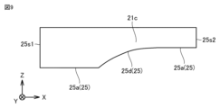
- the side shielding portion 21c has an upper surface, a front surface 25s2, a rear surface 25s1, and a lower surface 25.
- the upper surface is the surface opposite the lower surface 25.
- the lower surface 25 faces the workpiece 200. In other words, the upper surface and the lower surface 25 are both end surfaces in the Z direction.
- the front surface 25s2 is the surface opposite the rear surface 25s1.
- the rear surface 25s1 is the surface furthest from the welding torch 1 in the X direction. In other words, the front surface 25s2 and the rear surface 25s1 are both end surfaces in the X direction.
- the shape of the side shielding portion 21c may be any shape, but it is preferable that the shape of the lower surface 25 is a shape that follows the surface of the workpiece 200.
- the lower surface 25 may have a pair of horizontal portions 25a and an inclined portion 25b as shown in FIG. 3. In the X direction, the inclined portion 25b is arranged so as to be sandwiched between the pair of horizontal portions 25a.
- the pair of horizontal portions 25a are arranged spaced apart from each other in the Z direction.
- the pair of horizontal portions 25a are connected via the inclined portion 25b.
- the inclined portion 25b extends in a direction along the surface of the workpiece 200. In this way, the gap between the shielding portion 21 and the workpiece 200 can be made small.
- the after-shield gas is prevented from diffusing from the gap between the shielding portion 21 and the workpiece 200.
- the after-shield gas can sufficiently shield the welded portion A of the workpiece 200 from the atmosphere.
- FIGS. 8 and 9 are side views showing modified examples of side shielding portion 21c in welding device 100 according to embodiment 1.
- Welding device 100 shown in FIGS. 8 and 9 basically has the same configuration as welding device 100 shown in FIGS. 1 to 3, but the shape of side shielding portion 21c is different.
- the shape of the lower surface 25 may be any shape that follows the surface of the workpiece 200. Therefore, the shape of the lower surface 25 may be, for example, a shape that combines multiple straight line portions 25c as shown in FIG. 8. The multiple straight line portions 25c are arranged so as to be sandwiched between a pair of horizontal portions 25a.
- the lower surface 25 may have a curved surface portion 25d as shown in FIG. 9. The curved surface portion 25d is arranged so as to be sandwiched between a pair of horizontal portions 25a.
- the gap between the shielding portion 21 and the workpiece 200 can be made smaller.
- the after-shield gas is prevented from diffusing from the gap between the shielding portion 21 and the workpiece 200.
- the after-shield gas can sufficiently shield the welded portion A of the workpiece 200 from the atmosphere.
- the welding torch 1 may be placed in any position, but is preferably placed so as to be sandwiched between a pair of side shielding portions 21c in the Y direction. Specifically, as shown in FIG. 3, in a side view of the welding device 100, the welding torch 1 and electrode portion 1a preferably overlap the side shielding portion 21c in the X direction. From a different perspective, the welding torch 1 is preferably placed between the front surface 25s2 and the rear surface 25s1 of the side shielding portion 21c in the X direction. In this way, the after-shield gas, whose diffusion in the Y direction is suppressed by the side shielding portion 21c, hits the welded portion A. As a result, oxidation of the welded portion A is further suppressed.
- FIG. 10 is a side view showing the positional relationship between the side shielding portion 21c and the welding torch 1 in the welding device 100 according to the first embodiment.
- a part of the welding torch 1 does not have to overlap the side shielding portion 21c.
- the entire welding torch 1 does not have to overlap the side shielding portion 21c.
- the welding torch 1 may be positioned farther in the X direction than the front surface 25s2 of the side shielding portion 21c when viewed from the rear surface 25s1 of the side shielding portion 21c. In this way, since the electrode portion 1a of the welding torch 1 is not covered by the side shielding portion 21c, the positional relationship between the electrode portion 1a and the workpiece 200 can be easily confirmed visually.
- FIG. 11A is a side view showing a modified example of the first maintenance mechanism 22 in the welding device 100 according to the first embodiment.
- the welding device 100 shown in FIG. 11A basically has the same configuration as the welding device 100 shown in FIG. 1 to FIG. 3, but the structure of the first maintenance mechanism 22 is different.
- the first maintenance mechanism 22 may adopt any structure.
- the first maintenance mechanism 22 is composed of a shaft 22c and a rotating roller 22d.
- the shaft 22c connects the first maintenance mechanism 22 and the side shielding part 21c.
- the shaft 22c extends in the direction along the Y direction.
- the rotating roller 22d rotates around the shaft 22c as the central axis. As the workpiece 200 rotates, the rotating roller 22d can roll on the surface of the workpiece 200.
- the side shielding portion 21c has a rear surface 25s1 and a front surface 25s2.
- the side shielding portion 21c is connected to the rear shielding portion 21b at the rear surface 25s1.
- the front surface 25s2 is located opposite the rear surface 25s1 in the X direction.
- the first maintenance mechanism 22, including the shaft 22c and the rotating roller 22d, may be positioned so as to reduce the effect of heat generated by welding.
- the central axis of the shaft 22c may be positioned in the region Q1 in the X direction.
- the region Q1 is a region from the rear surface 25s1 to 50 percent of the width L in the X direction.
- the width L may be the distance from the rear surface 25s1 to the front surface 25s2 in the X direction.
- the region Q1 may be a region from the rear surface 25s1 to the central axis 1c of the welding torch 1.
- the rotating roller 22d is positioned near the rail 30, so that the rotating roller 22d can more easily roll on the surface of the workpiece 200.
- the first maintenance mechanism 22 may be connected to each of the pair of side shielding portions 21c so that the rotating roller 22d can contact both members.
- FIG. 11B is a side view showing a modified example of the first maintenance mechanism 22 in the welding device 100 according to embodiment 1.
- FIG. 11B corresponds to FIG. 11A.
- the first maintenance mechanism 22 shown in FIG. 11B basically has the same configuration as the first maintenance mechanism 22 shown in FIG. 11A, but differs in that a position adjustment part 23 is provided between the side shielding part 21c and the first maintenance mechanism 22.
- the position adjustment unit 23 may be, for example, a plate material as shown in FIG. 11B.
- the plate material has a plurality of through holes h1, h2, and h3. Screws are inserted into the through holes h1, h2, and h3. In other words, by inserting a screw into one of the through holes h1, h2, and h3, the first maintenance mechanism unit 22 is fixed to the plate material via the screw.
- the through holes h1 and h2 may be holes formed, for example, using a drill. As shown in FIG. 11B, the shape of the opening of the through holes h1 and h2 (the shape of the through holes h1 and h2 as viewed from the Y direction) may be circular or elliptical.
- Through hole h1 is spaced apart from through hole h2 in the X direction.
- the position in the X direction at which first maintenance mechanism 22 is fixed may be adjusted by inserting a screw into either through hole h1 or h2. In this manner, the relative position of first maintenance mechanism 22 with respect to side shielding portion 21c may be changed.
- the opening of the through hole h3 may extend in the Z direction.
- the width of the through hole h3 in the Z direction may be greater than its width in the X direction.
- the through hole h3 may be an elongated hole extending in the Z direction.
- the opening of the through hole h3 may extend in the X direction.
- the width of the through hole h3 in the X direction may be greater than its width in the Z direction.
- the through hole h3 may be an elongated hole extending in the X direction.
- FIG. 11C is a front view showing a modified example of the first maintenance mechanism 22 in the welding device 100 according to embodiment 1.
- the first maintenance mechanism 22 shown in FIG. 11C is basically configured similarly to the first maintenance mechanism 22 shown in FIGS. 1 to 3, but differs in that the first maintenance mechanism 22 has an adjuster bolt mechanism.
- the first maintenance mechanism 22 shown in FIG. 11C is a front view seen from the X direction.
- the ball roller 22a is connected to, for example, a cylindrical part 22f.
- a through hole may be formed in the second surface 22b2 of the bracket 22b.
- a male thread may be formed on the side of the cylindrical part 22f, and a screw thread may be formed on the inner surface of the through hole.
- the cylindrical part 22f is inserted into the through hole of the bracket 22b.
- the cylindrical part 22f is movable in a direction perpendicular to the second surface 22b2 (for example, a direction along the Z direction).
- the cylindrical part 22f is fixed to the bracket 22b by a nut. In this way, the relative position of the ball roller 22a of the first maintenance mechanism part 22 with respect to the side shielding part 21c may be changed.
- the ball roller 22a or the rotating roller 22d shown in FIG. 11A to FIG. 11C may not be used.
- the distance between the shielding part 21 and the workpiece 200 may be adjusted by directly contacting the side shielding part 21c or the bracket 22b with the workpiece 200.
- FIG. 11D is a side view showing a modified example of side shielding portion 21c in welding device 100 according to embodiment 1.
- Side shielding portion 21c shown in FIG. 11D is basically configured similarly to side shielding portion 21c shown in FIGS. 1 to 3, but differs in that side shielding portion 21c is provided with link member 23g.
- the link member 23g may be a plate-shaped member. One side forming the link member 23g follows the shape of the workpiece 200. A part of the side forming the link member 23g may be in contact with the workpiece 200.
- the link member 23g is connected to the side shielding part 21c via the shaft part 23g1.
- the link member 23g is provided with the shaft part 23g1.
- the shaft part 23g1 is disposed near the tip of the welding torch 1.
- the link member 23g and the side shielding part 21c are connected by the shaft part 23g1.
- the shaft part 23g1 extends in the direction along the Y direction.
- the link member 23g rotates around the shaft part 23g1 as the central axis.
- the link member 23g has a through hole h4.
- the opening of the through hole h4 extends along the rotation direction of the link member 23g.
- a fixing member 23g2 is inserted into the through hole h4.
- the fixing member 23g2 may fix the relative position of the link member 23g with respect to the side shielding portion 21c.
- the first maintenance mechanism 22 is disposed near the rear surface 25s1 in the X direction.
- the link member 23g further prevents the after-shield gas from diffusing from the gap between the shielding portion 21 and the workpiece 200.
- the after-shield gas can sufficiently shield the welded portion A of the workpiece 200 from the atmosphere without using the rail 30.
- FIG. 11E is a side view showing a modified example of the side shielding part 21c in the welding device 100 according to embodiment 1.
- the side shielding part 21c shown in FIG. 11E basically has the same configuration as the side shielding part 21c shown in FIGS. 1 to 3, but differs in that the side shielding part 21c has a movable part 8.
- the side shielding part 21c includes a main body part 81 and a movable part 82.
- the main body part 81 is connected to the rear shielding part 21b.
- the first maintenance mechanism part 22 is connected to the main body part 81.
- the movable part 82 is connected to the main body part 81 via a connecting part 84. In the X direction, the movable part 82 is disposed opposite the rear surface 25s1.
- the movable part 8 is formed by a plurality of connecting members 83. The plurality of connecting members 83 are connected to each other via connecting parts 84.
- Each of the multiple connecting members 83 can slide, for example, along the X direction and the Z direction.
- the connecting member 83 is provided with a fitting portion into which the connecting portion 84 fits.
- the fitting portion may be, for example, a through hole extending in the X direction.
- the position of the connecting member 83 in the X direction is determined by the position where the connecting portion 84 fits in the fitting portion.
- the connecting member 83 may rotate around the connecting portion 84. In this way, the connecting member 83 can slide along the X direction and the Y direction relative to the adjacent connecting members 83. Therefore, as shown in FIG. 11E, the multiple connecting members 83 can be arranged so that the lower ends of the multiple connecting members 83 follow the shape of the workpiece 200 (for example, the body portion 201 or the end portion 202 shown in FIG. 19).
- the after-shield gas is further prevented from diffusing through the gap between the shielding portion 21 and the workpiece 200.
- the after-shield gas can sufficiently shield the welded portion A of the workpiece 200 from the atmosphere.
- FIG. 12 is a schematic cross-sectional view showing a modified example of the after-shield gas jig 10 in the welding apparatus 100 according to the first embodiment.
- FIG. 12 corresponds to FIG. 3.
- the welding apparatus 100 shown in FIG. 12 basically has the same configuration as the welding apparatus 100 shown in FIGS. 1 to 3, but differs in that the after-shield gas jig 10 has a flame-retardant cover 24.
- the cover 24 is connected to the gas supply unit 20.
- the covers 24 may be in a pair.
- the pair of covers 24 are arranged outside the shielding portion 21 in the Y direction. Specifically, the pair of covers 24 may be arranged to sandwich a pair of side shielding portions 21c in the Y direction.
- the cover 24 is disposed near the workpiece 200 so that after-shield gas does not leak out from the gap between the shielding portion 21 and the workpiece 200.
- the cover 24 may be in contact with the workpiece 200. Therefore, the shape of the cover 24 may have notches formed at any point so that it conforms to the surface of the workpiece 200.
- the after-shield gas is further prevented from diffusing through the gap between the shielding portion 21 and the workpiece 200.
- the after-shield gas can sufficiently shield the welded portion A of the workpiece 200 from the atmosphere.
- the cover 24 is flame retardant.
- the material constituting the cover 24 is, for example, glass fiber, ceramic fiber, or carbon fiber.
- cover 24 If the cover 24 is in contact with the workpiece 200, wear and heat from welding will accelerate deterioration of the cover 24. Therefore, when welding the workpiece 200, the cover 24 does not need to be in contact with the workpiece 200.
- FIG. 13 is a perspective view showing a modified example of the after-shield gas jig 10 in the welding device 100 according to the first embodiment.
- FIG. 13 corresponds to FIG. 1.
- the welding device 100 shown in FIG. 13 basically has the same configuration as the welding device 100 shown in FIGS. 1 to 3, but differs in that the shielding portion 21 includes a front shielding portion 21d. Specifically, the front shielding portion 21d is connected to the front of the pair of side shielding portions 21c.
- the welding torch 1 is positioned between the convex portion 21g of the upper shielding portion 21a and the front shielding portion 21d in the X direction. In this way, the after-shield gas can sufficiently shield the welded portion A of the workpiece 200 from the atmosphere.
- the material constituting the after-shield gas jig 10 may be, for example, any of iron, stainless steel, copper, aluminum, and ceramic. In addition, multiple after-shield gas jigs 10 may be provided in the welding device 100.
- the after-shield gas tool 10 includes a gas supply unit 20.
- the gas supply unit 20 has an exhaust unit 21h.
- the exhaust unit 21h is capable of blowing out the after-shield gas toward the workpiece 200.
- the gas supply unit 20 has a shielding unit 21 and a first maintaining mechanism unit 22. When viewed from the direction in which the after-shield gas is blown out, the shielding unit 21 is disposed so as to surround the exhaust unit 21h.
- the first maintaining mechanism unit 22 can maintain a constant distance between the shielding unit 21 and the workpiece 200, independent of the position of the welding torch 1.
- the distance between the shielding portion 21 and the workpiece 200 is maintained constant, independent of the position of the welding torch 1. This prevents the after-shield gas from diffusing through the gap between the shielding portion 21 and the workpiece 200. As a result, the after-shield gas can adequately shield the welded portion A of the workpiece 200 from the atmosphere.
- the after-shield gas jig 10 includes a rail 30 and a first connection part 40.
- the rail 30 is connected to the gas supply part 20.
- the first connection part 40 is capable of sliding on the rail 30.
- the first connection part 40 can hold the welding torch 1. In this way, the distance between the shielding part 21 and the workpiece 200 is maintained constant by the first maintenance mechanism part 22 regardless of the position of the welding torch 1.
- the after-shield gas jig 10 includes a cover 24.
- the cover 24 is connected to the gas supply unit 20.
- the cover 24 is flame retardant. In this manner, the cover 24 can be positioned near the workpiece 200 when welding the workpiece 200. In other words, the after-shield gas is prevented from diffusing from the gap between the shielding unit 21 and the workpiece 200. As a result, the after-shield gas can sufficiently shield the welded portion A of the workpiece 200 from the atmosphere.
- the material constituting the cover 24 includes glass fiber, ceramic fiber, or carbon fiber.
- the cover 24 can be placed near the workpiece 200 when welding the workpiece 200.
- the after-shield gas can sufficiently shield the welded portion A of the workpiece 200 from the atmosphere.
- the welding device 100 includes a welding torch 1 and an after-shield gas fixture 10. In this way, the distance between the shielding portion 21 and the workpiece 200 is maintained constant, independent of the position of the welding torch 1. This prevents the after-shield gas from diffusing through the gap between the shielding portion 21 and the workpiece 200. As a result, the after-shield gas can adequately shield the welded portion A of the workpiece 200 from the atmosphere.
- Fig. 14 is a cross-sectional perspective view showing the gas supply unit 20 in the welding device 100 according to the second embodiment.
- the welding device 100 shown in Fig. 14 basically has the same configuration as the welding device 100 shown in Figs. 1 to 3, but the structure of the gas supply unit 20 is different.
- the shape of the upper surface shielding part 21a is not L-shaped but is flat as shown in Fig. 14.
- the convex part 21g is not formed in the upper surface shielding part 21a according to the second embodiment.
- a groove is formed in each of the top shielding portion 21a, the rear shielding portion 21b, and the pair of side shielding portions 21c.
- the outer periphery of the filter 21f is held in the discharge portion 21h so that it fits into the grooves of the top shielding portion 21a, the rear shielding portion 21b, and the pair of side shielding portions 21c. Therefore, in a side view of the filter 21f, the shape of the filter 21f has a curved portion as shown in FIG. 14.
- the after-shield gas supplied from the piping joint 51 can be blown out in a direction perpendicular to the tangent of the workpiece 200 and in a direction along the tangent.
- a direction along the tangent means a direction parallel to the tangent and a direction inclined at an angle of 30° or less to the tangent.
- the after-shield gas blows out in directions along the X and Z directions through the filter 21f.
- the welding device 100 in the second embodiment can blow out the after-shield gas toward the workpiece 200 over a wider area than the welding device 100 in the first embodiment.
- the after-shield gas can be blown out in a direction perpendicular to and along a tangent to the workpiece 200. In this manner, the after-shield gas can be supplied to a wide area of the workpiece 200. As a result, the after-shield gas can sufficiently shield the welded portion A of the workpiece 200 from the atmosphere.
- Embodiment 3. are cross-sectional perspective views showing the gas supply unit 20 in the welding device 100 according to the third embodiment.
- FIG. 15A and FIG. 16 correspond to FIG. 14.
- the welding device 100 shown in FIG. 15A and FIG. 16 basically has the same configuration as the welding device 100 shown in FIG. 14, but is different in that the welding torch 1 is disposed at an incline with respect to the workpiece 200.
- an inclined portion 26 is formed on the upper surface of the upper shielding portion 21a.
- the inclined portion 26 is disposed at a corner of the upper shielding portion 21a adjacent to the welding torch 1.
- the inclined portion 26 is a surface on which the welding torch 1 is mounted.
- the welding torch 1 is placed on the inclined portion 26.
- the arm portion 44 (not shown) is positioned so that it can hold the inclined welding torch 1. In this way, the position of the welded portion A becomes farther away.
- the shape of the filter 21f has a curved portion. Therefore, the after-shield gas supplied from the piping joint 51 blows out in a direction perpendicular to the tangent of the workpiece 200 and in a direction along the tangent. As a result, the after-shield gas can sufficiently shield the welded portion A of the workpiece 200 from the atmosphere.
- the welding torch 1 is inclined relative to the workpiece 200. From a different perspective, the central axis 1c of the electrode portion 1a is inclined relative to the tangent line of the workpiece 200. In this way, the pressure from the arc applied to the welded portion A is dispersed not only in a direction perpendicular to the tangent line of the workpiece 200 (Z direction), but also in a direction parallel to the tangent line (X direction). As a result, the pressure in the Z direction applied to the welded portion A is reduced, and the welded portion A is prevented from becoming a weld pool and melting away.
- the welding torch 1 when the welding torch 1 is positioned at an angle, as described above in FIG. 10, in a side view of the welding device 100, a portion of the welding torch 1 does not have to overlap the side shielding portion 21c, and the entire welding torch 1 does not have to overlap the side shielding portion 21c.
- the inclined portion 26 is formed by a flat surface.
- the shape of the surface forming the inclined portion 26 may be changed to match the outer peripheral shape of the welding torch 1.
- FIG. 15B is a cross-sectional perspective view showing a modified example of the gas supply unit 20 in the welding device 100 according to embodiment 3.
- FIG. 15B corresponds to FIG. 15A.
- the gas supply unit 20 shown in FIG. 15B basically has the same configuration as the gas supply unit 20 shown in FIG. 15A, but differs in that the inclined portion 26 is formed by a curved surface. Specifically, the shape of the inclined portion 26 is concave in the direction away from the welding torch 1.
- the welding torch 1 is cylindrical. From a different perspective, the outer peripheral shape of the welding torch 1 is circular. In this way, when the outer peripheral shape of the welding torch 1 is circular, the gap formed between the inclined portion 26 and the welding torch 1 is small. As a result, the after-shield gas is prevented from diffusing from the gap. Also, the air is prevented from flowing into the welded portion A from the gap.
- the gas supply section 20 may include a diffuser plate 52 as shown in FIGS. 5 to 7.
- the welding torch 1 has an electrode portion 1a.
- the central axis 1c of the electrode portion 1a is inclined with respect to the tangent line of the workpiece 200. In this way, the pressure applied to the welded portion A by the arc is reduced. As a result, the welded portion A is prevented from becoming a weld pool and melting through.
- FIG. 17 is a perspective view of a welding device 100 according to a fourth embodiment.
- FIG. 17 corresponds to FIG. 1.
- the welding device 100 shown in FIG. 17 basically has the same configuration as the welding device 100 shown in FIG. 1, but differs in that the distance between the welding torch 1 and the workpiece 200 is adjusted by a maintenance mechanism unit independently of the position of the shielding unit 21.
- the welding device 100 includes a second connection portion 40y and a pair of rails 30y.
- the second connection portion 40y is connected to the welding torch 1.
- the second connection portion 40y basically has the same configuration as the first connection portion 40x.
- the second connection portion 40y can hold the welding torch 1.
- the second connection portion 40y includes a sliding portion 41y, a first block portion 42y, a second block portion 43y (not shown), an arm portion 44y, and a third block portion 45y.
- the sliding portion 41y is connected to the rail 30y and can slide on the rail 30y.
- the first block portion 42y is connected to be fixed to the sliding portion 41y.
- the second block portion 43y is connected to be fixed to the first block portion 42y.
- the arm portion 44y is connected to be fixed to the second block portion 43y. The arm portion 44y can hold the welding torch 1.
- the third block portion 45y is connected so as to be fixed to the arm portion 44y. As shown in FIG. 17, in a side view of the welding device 100, the third block portion 45y has a rectangular shape. The third block portion 45y extends in the Z direction.
- the second connection part 40y has a second maintenance mechanism part 22y as a maintenance mechanism part.
- the second maintenance mechanism part 22y has a configuration similar to that of the first maintenance mechanism part 22x, but differs in that the second maintenance mechanism part 22y is connected so as to be fixed to the third block part 45y.
- the second maintenance mechanism part 22y maintains a constant distance between the welding torch 1 and the workpiece 200.
- the distance between the welding torch 1 and the workpiece 200 is maintained constant by the second maintaining mechanism 22y.
- the distance between the shielding part 21 and the workpiece 200 is maintained constant by the first maintaining mechanism 22x.
- the relative positions of the shielding part 21 and the welding torch 1 with respect to the workpiece 200 are determined independently of each other. As a result, if the workpiece 200 is displaced due to eccentricity or the like, the relative positions of the welding torch 1 and the shielding part 21 with respect to the workpiece 200 do not change and are maintained constant even if the workpiece 200 is rotating.
- Fig. 18 is a schematic diagram for explaining the configuration of a modified example of welding device 100 according to embodiment 4.
- Welding device 100 shown in Fig. 18 basically has the same configuration as welding device 100 shown in Fig. 17, but differs in that the distance between welding torch 1 and workpiece 200 is adjusted based on the voltage of the arc generated from electrode portion 1a of welding torch 1.
- welding device 100 includes processing circuit 3. As shown in Fig. 18, processing circuit 3 has control portion 3a and detection portion 3b.
- the detection unit 3b is connected to the control unit 3a.
- the detection unit 3b detects the voltage of the arc generated from the electrode unit 1a of the welding torch 1.
- a voltage sensor that measures the voltage of the arc can be used as the detection unit 3b.
- the control unit 3a controls the drive unit 2 according to the voltage of the arc detected by the detection unit 3b. Specifically, the control unit 3a controls the drive unit 2 so that the voltage of the arc approaches a preset voltage. As a result, the drive unit 2 can change the position of the welding torch 1 relative to the workpiece 200. This makes it possible to adjust the position of the welding torch 1, i.e., the position of the electrode unit 1a.
- the distance between the welding torch 1 and the workpiece 200 may be adjusted based on the voltage of the arc generated from the electrode portion 1a, independent of the position of the shielding portion 21.
- the relative positions of the shielding portion 21 and the welding torch 1 with respect to the workpiece 200 are determined independently of each other.
- the relative positions of the welding torch 1 and the shielding portion 21 with respect to the workpiece 200 do not change, even if the workpiece 200 is rotating, but are maintained or adjusted constant.
- the welding device 100 includes a driving unit 2 and a processing circuit 3.
- the driving unit 2 is connected to the welding torch 1.
- the processing circuit 3 detects the voltage of an arc generated from the electrode portion 1a of the welding torch 1.
- the driving unit 2 adjusts the distance between the welding torch 1 and the workpiece 200 based on the voltage.
- the distance between the welding torch 1 and the workpiece 200 is adjusted based on the voltage of the arc generated by the electrode portion 1a, independent of the position of the shielding portion 21. In other words, the relative positions of the shielding portion 21 and the welding torch 1 with respect to the workpiece 200 are determined independently of each other.
- Fig. 19 is a schematic diagram of a welding facility 300 according to a fifth embodiment.
- the welding facility 300 shown in Fig. 19 is for welding a cylindrical structure as a workpiece 200.
- the cylindrical structure is, for example, a hot water tank for a water heater.
- the hot water tank is composed of a body portion 201 and a pair of end portions 202.
- the body portion 201 is, for example, a cylindrical thin plate manufactured by roll forming.
- the end portions 202 are bowl-shaped thin plates.
- the material constituting the hot water tank may be, for example, a steel plate such as stainless steel.
- the body portion 201 is positioned so as to be sandwiched between a pair of ends 202.
- the ends 202 are welded to the end surface of the body portion 201 by the welding equipment 300. In other words, the location where the body portion 201 and the ends 202 are connected becomes the welded portion A.
- the welding equipment 300 mainly includes a welding device 100 according to any one of the first to fourth embodiments, a holding mechanism 301, and a rotating mechanism 302.
- the holding mechanism 301 holds the workpiece 200.
- the rotating mechanism 302 rotates the workpiece 200.
- the holding mechanism 301 holds the end 202.
- the end 202 is connected to the body 201.
- the body 201 is held by the welding equipment 300 with the end 202 in contact with both ends of the body 201.
- the workpiece 200 is welded while the body 201 and the pair of end 202 are rotated by the rotating mechanism 302. In this manner, a hot water storage tank is manufactured in which the body 201 and the pair of end 202 are assembled together.
- the welding device 100 has a second holding mechanism 22y as shown in FIG. 17.
- the workpiece 200 is a cylindrical structure such as a hot water tank or a can body composed of a body 201 and a pair of ends 202. It is held by the holding mechanism 301 with the ends 202 in contact with both ends of the body 201.
- a moving step is performed.
- the workpiece 200 is moved close to the welding device 100. Specifically, the workpiece 200 is moved so as to come into contact with the first maintenance mechanism 22x and the second maintenance mechanism 22y. Each of the first maintenance mechanism 22x and the second maintenance mechanism 22y is in contact with the surface of either the body portion 201 or the end portion 202.
- the welding process is performed.
- the workpiece 200 is welded.
- the workpiece 200 is rotated by the rotation mechanism 302.
- the welding torch 1 generates an arc toward the workpiece 200.
- the after-shield gas is blown from the gas supply unit 20 toward the workpiece 200.
- the first maintenance mechanism 22x maintains the distance between the shielding part 21 and the workpiece 200 constant even if the workpiece 200 is rotating.
- the second maintenance mechanism 22y maintains the distance between the welding torch 1 and the workpiece 200 constant.
- the relative positions of the shielding part 21 and the welding torch 1 with respect to the workpiece 200 are determined independently of each other. Therefore, the body part 201 and the end part 202 are welded in a state where the welded part A of the workpiece 200 is sufficiently shielded from the atmosphere by the after-shield gas.
- a hot water tank is manufactured in which the body portion 201 and a pair of end portions 202 are assembled together.
- the welding device 100 is equipped with a processing circuit 3 as shown in FIG. 18.
- the workpiece 200 is a hot water tank composed of a body portion 201 and a pair of end portions 202. It is held by a holding mechanism portion 301 with the end portions 202 in contact with both ends of the body portion 201.
- a moving process is carried out.
- the workpiece 200 is moved close to the welding device 100. Specifically, the workpiece 200 is moved so as to come into contact with the first maintenance mechanism 22.
- the first maintenance mechanism 22 is in contact with the surface of either the body portion 201 or the end portion 202.
- the welding process is performed.
- the workpiece 200 is welded.
- the workpiece 200 is rotated by the rotation mechanism 302.
- the welding torch 1 generates an arc toward the workpiece 200.
- After-shield gas is blown from the gas supply unit 20 toward the workpiece 200.
- the first maintenance mechanism unit 22 maintains the distance between the shielding unit 21 and the workpiece 200 constant even if the workpiece 200 is rotating.
- the drive unit 2 adjusts the distance between the welding torch 1 and the workpiece 200. Specifically, the distance between the welding torch 1 and the workpiece 200 is adjusted based on the voltage of the arc generated from the electrode unit 1a.
- the relative positions of the shielding unit 21 and the welding torch 1 with respect to the workpiece 200 are determined independently of each other. Therefore, the body portion 201 and the end portion 202 are welded while the welded portion A of the workpiece 200 is sufficiently shielded from the atmosphere by the after-shield gas.
- a hot water tank is manufactured in which the body portion 201 and a pair of end portions 202 are assembled together.
- a welding facility 300 includes a welding device 100, a holding mechanism 301, and a rotating mechanism 302.
- the holding mechanism 301 holds a workpiece 200.
- the rotating mechanism 302 rotates the workpiece 200.
- the relative positions of the shielding portion 21 and the welding torch 1 with respect to the workpiece 200 can be determined independently of each other, allowing welding of a cylindrical structure such as a hot water tank.
- the after-shield gas sufficiently shields the welded portion A of the workpiece 200 from the atmosphere.
- the welding method includes a step of moving the workpiece 200 near the welding device 100, and a step of welding the workpiece 200.
- the moving step the workpiece 200 is moved so as to come into contact with the first maintenance mechanism 22x.
- the welding torch 1 generates an arc toward the workpiece 200.
- after-shield gas is blown from the gas supply unit 20 toward the workpiece 200.
- the first maintenance mechanism 22x maintains a constant distance between the shielding unit 21 and the workpiece 200.
- the second maintenance mechanism 22y maintains a constant distance between the welding torch 1 and the workpiece 200.
- the relative positions of the shielding portion 21 and the welding torch 1 with respect to the workpiece 200 can be determined independently of each other, allowing welding of a cylindrical structure such as a hot water tank.
- the after-shield gas sufficiently shields the welded portion A of the workpiece 200 from the atmosphere.
- the welding method includes a step of moving the workpiece 200 near the welding device 100, and a step of welding the workpiece 200.
- the moving step the workpiece 200 is moved so as to come into contact with the first maintaining mechanism 22.
- the welding torch 1 generates an arc toward the workpiece 200.
- after-shield gas is blown from the gas supply unit 20 toward the workpiece 200.
- the first maintaining mechanism 22 maintains a constant distance between the shielding unit 21 and the workpiece 200.
- the drive unit 2 adjusts the distance between the welding torch 1 and the workpiece 200.
- the relative positions of the shielding portion 21 and the welding torch 1 with respect to the workpiece 200 can be determined independently of each other, allowing welding of a cylindrical structure such as a hot water tank.
- the after-shield gas sufficiently shields the welded portion A of the workpiece 200 from the atmosphere.
- Appendix 1 a gas supply unit having an exhaust unit capable of blowing out an after-shield gas toward the workpiece; the gas supply unit has a shielding unit and a first maintenance mechanism unit, When viewed from the direction in which the aftershield gas is blown out, The shielding portion is disposed so as to surround the exhaust portion, An after-shield gas jig, wherein the first maintenance mechanism can maintain a constant distance between the shielding portion and the workpiece, independent of the position of the welding torch.
- Appendix 2 A rail connected to the gas supply; a first connection portion slidable on the rail; 2.
- Appendix 3 a cover connected to the gas supply;
- Appendix 4 The after-shield gas tool according to claim 3, wherein a material constituting the cover includes any one of glass fiber, ceramic fiber, and carbon fiber.
- Appendix 5 5.
- the shielding portion has a front surface and a rear surface that is a surface opposite to the front surface in the X direction, 6.
- Appendix 11 11.
- Appendix 12 The welding torch; A welding apparatus comprising an after-shield gas jig according to any one of claims 1 to 11.
- Appendix 13 The welding torch has an electrode portion, 13.
- the welding device of claim 12 wherein a central axis of the electrode portion is inclined with respect to a tangent to the workpiece.
- Appendix 14 a second connection portion connected to the welding torch;
- the second connection portion has a second maintaining mechanism portion, 14.
- the welding device according to claim 12 or 13, wherein the second maintaining mechanism can maintain a constant distance between the welding torch and the workpiece.
- Appendix 15 A drive unit connected to the welding torch; a processing circuit for detecting a voltage of an arc generated by the welding torch; 15. The welding device according to any one of claims 12 to 14, wherein the drive unit adjusts a distance between the welding torch and the workpiece based on the voltage.
- Appendix 16 If the direction in which the welding torch is disposed as viewed from the discharge portion is defined as an X direction, the shielding portion has a front surface and a rear surface that is a surface opposite to the front surface in the X direction, 16.
- the first maintenance mechanism includes a rotating roller that is disposed in a region where a distance from the rear surface is 50 percent or less of a distance in the X direction from the rear surface to the front surface, or in a region from the rear surface to the welding torch.
- a position adjustment unit is provided between the shielding unit and the first maintenance mechanism unit, The welding device according to any one of claims 12 to 16, wherein the position adjustment unit changes a relative position of the first maintenance mechanism unit with respect to the shielding unit.
- a link member is provided on the shielding portion, 18. The welding device of claim 12, wherein a relative position of the link member with respect to the shielding portion changes.
- the workpiece is moved so as to come into contact with the first maintaining mechanism;
- the welding torch generates an arc toward the workpiece,
- the after-shield gas is blown from the gas supply portion toward the workpiece,
- the first maintaining mechanism maintains a constant distance between the shielding part and the workpiece,
- a welding method wherein the second maintaining mechanism maintains a constant distance between the welding torch and the workpiece.
- the workpiece is moved so as to come into contact with the first maintaining mechanism;
- the welding torch generates an arc toward the workpiece,
- the after-shield gas is blown from the gas supply portion toward the workpiece,
- the first maintaining mechanism maintains a constant distance between the shielding part and the workpiece,
- a welding method wherein the driving unit adjusts a distance between the welding torch and the workpiece. (Appendix 25) 25.
- Appendix 26 A manufacturing method of a cylindrical structure using the welding method according to any one of Supplementary Note 23 to Supplementary Note 25, A method for manufacturing a cylindrical structure, wherein the workpiece is a body portion and a pair of end portions that constitute the cylindrical structure.
Landscapes
- Engineering & Computer Science (AREA)
- Physics & Mathematics (AREA)
- Plasma & Fusion (AREA)
- Mechanical Engineering (AREA)
- Arc Welding In General (AREA)
- Butt Welding And Welding Of Specific Article (AREA)
Priority Applications (3)
| Application Number | Priority Date | Filing Date | Title |
|---|---|---|---|
| JP2025528061A JPWO2024262484A1 (https=) | 2023-06-21 | 2024-06-18 | |
| GB2518636.2A GB2644520A (en) | 2023-06-21 | 2024-06-18 | After-shield gas jig, welding device, welding equipment, welding method, and method for manufacturing cylindrical structure |
| DE112024002644.3T DE112024002644T5 (de) | 2023-06-21 | 2024-06-18 | Nachschutzgasvorrichtung, Schweißvorrichtung, Schweißausrüstung, Schweißverfahren und Verfahren des Herstellens einer zylindrischen Struktur |
Applications Claiming Priority (2)
| Application Number | Priority Date | Filing Date | Title |
|---|---|---|---|
| JP2023101324 | 2023-06-21 | ||
| JP2023-101324 | 2023-06-21 |
Publications (1)
| Publication Number | Publication Date |
|---|---|
| WO2024262484A1 true WO2024262484A1 (ja) | 2024-12-26 |
Family
ID=93935454
Family Applications (1)
| Application Number | Title | Priority Date | Filing Date |
|---|---|---|---|
| PCT/JP2024/022005 Ceased WO2024262484A1 (ja) | 2023-06-21 | 2024-06-18 | アフターシールドガス治具、溶接装置、溶接設備、溶接方法および円筒構造物の製造方法 |
Country Status (4)
| Country | Link |
|---|---|
| JP (1) | JPWO2024262484A1 (https=) |
| DE (1) | DE112024002644T5 (https=) |
| GB (1) | GB2644520A (https=) |
| WO (1) | WO2024262484A1 (https=) |
Citations (5)
| Publication number | Priority date | Publication date | Assignee | Title |
|---|---|---|---|---|
| JPS5695479U (https=) * | 1979-12-20 | 1981-07-29 | ||
| JPH09164482A (ja) * | 1995-12-18 | 1997-06-24 | Nkk Corp | 電極回転式非消耗電極アーク溶接における開先倣い方法及び開先倣い制御装置 |
| JP2003001491A (ja) * | 2001-06-20 | 2003-01-08 | Shinba Iron Works Inc | 溶接用芯金 |
| JP2022099822A (ja) * | 2020-12-23 | 2022-07-05 | 株式会社神戸製鋼所 | 積層造形物の製造方法及び製造装置 |
| JP2022149068A (ja) * | 2021-03-25 | 2022-10-06 | 大陽日酸株式会社 | 配管の自動溶接又は溶断装置 |
Family Cites Families (1)
| Publication number | Priority date | Publication date | Assignee | Title |
|---|---|---|---|---|
| JPS5695479A (en) * | 1979-12-28 | 1981-08-01 | Nisshin Steel Co Ltd | Manufacture of metal-clad material |
-
2024
- 2024-06-18 JP JP2025528061A patent/JPWO2024262484A1/ja active Pending
- 2024-06-18 GB GB2518636.2A patent/GB2644520A/en active Pending
- 2024-06-18 DE DE112024002644.3T patent/DE112024002644T5/de active Pending
- 2024-06-18 WO PCT/JP2024/022005 patent/WO2024262484A1/ja not_active Ceased
Patent Citations (5)
| Publication number | Priority date | Publication date | Assignee | Title |
|---|---|---|---|---|
| JPS5695479U (https=) * | 1979-12-20 | 1981-07-29 | ||
| JPH09164482A (ja) * | 1995-12-18 | 1997-06-24 | Nkk Corp | 電極回転式非消耗電極アーク溶接における開先倣い方法及び開先倣い制御装置 |
| JP2003001491A (ja) * | 2001-06-20 | 2003-01-08 | Shinba Iron Works Inc | 溶接用芯金 |
| JP2022099822A (ja) * | 2020-12-23 | 2022-07-05 | 株式会社神戸製鋼所 | 積層造形物の製造方法及び製造装置 |
| JP2022149068A (ja) * | 2021-03-25 | 2022-10-06 | 大陽日酸株式会社 | 配管の自動溶接又は溶断装置 |
Also Published As
| Publication number | Publication date |
|---|---|
| JPWO2024262484A1 (https=) | 2024-12-26 |
| GB2644520A (en) | 2026-04-15 |
| DE112024002644T5 (de) | 2026-04-23 |
Similar Documents
| Publication | Publication Date | Title |
|---|---|---|
| JP5346899B2 (ja) | 水平型自動溶接装置 | |
| US8946584B2 (en) | Angled cut height control system for a plasma arch torch | |
| US10245671B2 (en) | Weld overlay system | |
| CN101456098A (zh) | 等离子焊焊接容器筒体环缝的方法 | |
| US20120298632A1 (en) | Angled cut height control system for a plasma arch torch | |
| US20080296271A1 (en) | Method and Apparatus for Laser Welding | |
| KR20190068161A (ko) | 원형 절단기 | |
| WO2024262484A1 (ja) | アフターシールドガス治具、溶接装置、溶接設備、溶接方法および円筒構造物の製造方法 | |
| KR20180080529A (ko) | 파이프 자동 용접장치 | |
| JP6965470B1 (ja) | 配管の自動溶接又は溶断装置 | |
| KR102582885B1 (ko) | 용접용 접동 구리 백킹판, 용접 장치 및 용접 방법 | |
| CN115156718A (zh) | 激光-mig电弧复合焊接装置及复合焊接方法 | |
| CN115194332A (zh) | 用于曲线焊缝的激光-tig电弧复合焊接装置及方法 | |
| JP4848204B2 (ja) | 構造物の肉盛溶接装置 | |
| JP2022099822A (ja) | 積層造形物の製造方法及び製造装置 | |
| CA2462176A1 (en) | Welding shield gas and welding method | |
| JP3117287B2 (ja) | 消耗電極式アーク溶接方法 | |
| CN216802038U (zh) | 一种快速焊接设备 | |
| JP2019166534A (ja) | シールドボックス、溶接装置および溶接方法 | |
| KR20030006186A (ko) | 원호 용접용 극소 협개선 미그 용접장치 | |
| KR102615483B1 (ko) | 비원형 플레이트의 용접 장치 및 비원형 플레이트 구조체의 제조 방법 | |
| JPH0716746A (ja) | 厚板横向き自動溶接方法およびその装置 | |
| CN120326231B (zh) | 一种起重机转台零件焊接装置及焊接方法 | |
| KR101392450B1 (ko) | 용접 장치 및 그를 이용한 용접 방법 | |
| KR102712835B1 (ko) | 용접 장치 |
Legal Events
| Date | Code | Title | Description |
|---|---|---|---|
| 121 | Ep: the epo has been informed by wipo that ep was designated in this application |
Ref document number: 24825885 Country of ref document: EP Kind code of ref document: A1 |
|
| ENP | Entry into the national phase |
Ref document number: 202518636 Country of ref document: GB Kind code of ref document: A Free format text: PCT FILING DATE = 20240618 |
|
| WWE | Wipo information: entry into national phase |
Ref document number: 2518636.2 Country of ref document: GB |
|
| ENP | Entry into the national phase |
Ref document number: 2025528061 Country of ref document: JP Kind code of ref document: A |
|
| WWE | Wipo information: entry into national phase |
Ref document number: 112024002644 Country of ref document: DE |