WO2024262202A1 - バッテリ台及びこれを備える作業機 - Google Patents
バッテリ台及びこれを備える作業機 Download PDFInfo
- Publication number
- WO2024262202A1 WO2024262202A1 PCT/JP2024/017974 JP2024017974W WO2024262202A1 WO 2024262202 A1 WO2024262202 A1 WO 2024262202A1 JP 2024017974 W JP2024017974 W JP 2024017974W WO 2024262202 A1 WO2024262202 A1 WO 2024262202A1
- Authority
- WO
- WIPO (PCT)
- Prior art keywords
- battery
- fixing
- fixing device
- stand
- inclined portion
- Prior art date
- Legal status (The legal status is an assumption and is not a legal conclusion. Google has not performed a legal analysis and makes no representation as to the accuracy of the status listed.)
- Ceased
Links
Images






Classifications
-
- H—ELECTRICITY
- H01—ELECTRIC ELEMENTS
- H01M—PROCESSES OR MEANS, e.g. BATTERIES, FOR THE DIRECT CONVERSION OF CHEMICAL ENERGY INTO ELECTRICAL ENERGY
- H01M50/00—Constructional details or processes of manufacture of the non-active parts of electrochemical cells other than fuel cells, e.g. hybrid cells
- H01M50/20—Mountings; Secondary casings or frames; Racks, modules or packs; Suspension devices; Shock absorbers; Transport or carrying devices; Holders
- H01M50/262—Mountings; Secondary casings or frames; Racks, modules or packs; Suspension devices; Shock absorbers; Transport or carrying devices; Holders with fastening means, e.g. locks
-
- H—ELECTRICITY
- H01—ELECTRIC ELEMENTS
- H01M—PROCESSES OR MEANS, e.g. BATTERIES, FOR THE DIRECT CONVERSION OF CHEMICAL ENERGY INTO ELECTRICAL ENERGY
- H01M50/00—Constructional details or processes of manufacture of the non-active parts of electrochemical cells other than fuel cells, e.g. hybrid cells
- H01M50/20—Mountings; Secondary casings or frames; Racks, modules or packs; Suspension devices; Shock absorbers; Transport or carrying devices; Holders
- H01M50/244—Secondary casings; Racks; Suspension devices; Carrying devices; Holders characterised by their mounting method
-
- H—ELECTRICITY
- H01—ELECTRIC ELEMENTS
- H01M—PROCESSES OR MEANS, e.g. BATTERIES, FOR THE DIRECT CONVERSION OF CHEMICAL ENERGY INTO ELECTRICAL ENERGY
- H01M50/00—Constructional details or processes of manufacture of the non-active parts of electrochemical cells other than fuel cells, e.g. hybrid cells
- H01M50/20—Mountings; Secondary casings or frames; Racks, modules or packs; Suspension devices; Shock absorbers; Transport or carrying devices; Holders
- H01M50/249—Mountings; Secondary casings or frames; Racks, modules or packs; Suspension devices; Shock absorbers; Transport or carrying devices; Holders specially adapted for aircraft or vehicles, e.g. cars or trains
-
- H—ELECTRICITY
- H01—ELECTRIC ELEMENTS
- H01M—PROCESSES OR MEANS, e.g. BATTERIES, FOR THE DIRECT CONVERSION OF CHEMICAL ENERGY INTO ELECTRICAL ENERGY
- H01M2220/00—Batteries for particular applications
- H01M2220/20—Batteries in motive systems, e.g. vehicle, ship, plane
-
- Y—GENERAL TAGGING OF NEW TECHNOLOGICAL DEVELOPMENTS; GENERAL TAGGING OF CROSS-SECTIONAL TECHNOLOGIES SPANNING OVER SEVERAL SECTIONS OF THE IPC; TECHNICAL SUBJECTS COVERED BY FORMER USPC CROSS-REFERENCE ART COLLECTIONS [XRACs] AND DIGESTS
- Y02—TECHNOLOGIES OR APPLICATIONS FOR MITIGATION OR ADAPTATION AGAINST CLIMATE CHANGE
- Y02E—REDUCTION OF GREENHOUSE GAS [GHG] EMISSIONS, RELATED TO ENERGY GENERATION, TRANSMISSION OR DISTRIBUTION
- Y02E60/00—Enabling technologies; Technologies with a potential or indirect contribution to GHG emissions mitigation
- Y02E60/10—Energy storage using batteries
Definitions
- the present invention relates to a battery stand for fixing a battery to a work machine and a work machine equipped with the battery stand.
- the battery stand disclosed in Patent Document 1 has a mounting wall on which a first battery and a second battery having different mounting formats can be selectively mounted, and a restricting member provided on the mounting wall that restricts the movement of the first battery and the second battery toward the front side, and the restricting member has a restricting portion that engages with a first engaging protrusion provided on the lower front side of the second battery to restrict the upward movement of the second battery.
- the battery stand in Patent Document 1 can accommodate batteries with different mounting styles.
- the battery is fixed to the battery stand by a pair of rod members (a first rod member and a second rod member) and an attachment stay. Therefore, when attaching or detaching the battery to or from the battery stand, it is necessary to attach and detach the pair of rod members.
- the present invention was made in consideration of the above problems, and aims to provide a battery stand that can securely and easily fix a battery, and a work machine equipped with the battery stand.
- a battery stand comprises a mounting base on which a battery is placed, a restricting member disposed on the rear side of the battery and restricting the rearward movement of the battery, and a fixing member disposed from above or above the restricting member to the front side of the battery and fixing the battery, the fixing member having a first fixing device disposed on the top side of the battery, a second fixing device disposed on the front side of the battery, and a connecting portion connecting the first fixing device and the second fixing device, the connecting portion comprising an inclined portion provided on one of the first fixing device and the second fixing device, inclined in a direction approaching the rear side of the battery as it goes upward, and a holding member that adjustably holds the connecting position of the other of the first fixing device and the second fixing device relative to the inclined portion.
- the first fixing device may have one end connected to the upper or top of the restricting member and the other end disposed above the front of the battery, and the second fixing device may have the inclined portion of the connecting portion formed at one end and the other end connected to the mounting base.
- the second fixing device may be bent at a midpoint, and the portion extending from the midpoint to the one end may form the inclined portion in the inclined direction.
- the regulating member extends from the mounting base above the battery, and the one end of the first fixing device is connected to an upper portion of the regulating member so as to be swingable in the up-down direction, and the other end of the second fixing device is connected to the mounting base so as to be swingable in the front-rear direction of the battery.
- the holding member may change the connection position of the other of the first fastener and the second fastener relative to the inclined portion by moving along the inclined portion.
- the other of the first and second fasteners may have an inclined surface that is inclined in a direction intersecting the inclination direction, and the holding member may hold the connection position of the other of the first and second fasteners relative to the inclined portion by abutting against the inclined surface.
- the inclined portion may have a screw groove formed therein, and the retaining member may be a fastening member that screws into the screw groove.
- the fixing member may be located on the inner side in the width direction of the battery placed on the mounting table.
- the fixing member may be provided on the inner side in the width direction of the battery placed on the mounting table.
- the battery may include clamp members disposed between the top surface of the battery and the first fastener, and between the front surface of the battery and the second fastener, and the clamp members may press the top surface of the battery downward with the first fastener and press the front surface backward with the second fastener.
- the device may include a force transmission member disposed between the fixing member and the battery, which transmits the pressing force of the fixing member to the battery.
- the fixing member may directly or indirectly abut against an upper front corner of the battery, and apply rearward and downward pressure to the battery.
- a working machine according to one aspect of the present invention is equipped with the battery stand described above.
- the battery stand and the work machine equipped with the battery stand according to the present invention allow the battery to be fixed easily and securely.
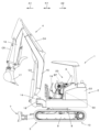
- FIG. 1 is a perspective view of a work machine equipped with a battery stand of the present invention
- 1 is a side view of a work machine equipped with a battery stand of the present invention
- FIG. 2 is a plan view showing the arrangement of the batteries relative to the aircraft body.
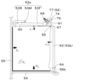
- FIG. 2 is a perspective view of the battery stand of the first embodiment, as viewed from diagonally above on the right. 2 is a cross-sectional view of the battery stand of the first embodiment taken along the center in the left-right direction.
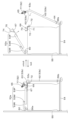
- FIG. 5A to 5C are diagrams illustrating an operation of attaching and detaching a battery to and from the battery stand of the first embodiment.
- FIG. 13 is a view showing the fixing member in a state where the fastening member is loosened.
- FIG. 11 is a diagram showing the relationship between the pressing force applied from the fixing member and the friction surface when the fastening member is fastened.
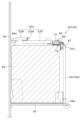
- FIG. 13 is a side view showing the relationship between a holding member, a pressing member, and a bracket in the second embodiment.
- FIG. 13 is a side view showing an embodiment in which the fixing member is indirectly brought into contact with the upper front portion of the battery.
- FIG. 13 is a side view showing an embodiment in which the fixing member is directly brought into contact with the front upper portion of the battery.
- FIG. 1 is a perspective view showing a work machine 1 equipped with a battery stand 50 of the first embodiment.
- FIG. 2 is a side view of the work machine 1.
- the battery stand 50 secures the battery BT to a working machine 1 equipped with a working device 4, such as a construction machine or an agricultural machine.
- the battery stand 50 of the present invention may also secure the battery BT to a vehicle other than the working machine 1, such as a traveling vehicle such as a tractor or cultivator.
- a backhoe which is a rotating working machine, is exemplified as the working machine 1.
- the work machine 1 of the first embodiment includes a machine body (swivel base) 2, a traveling device 3, and a work device 4.
- the machine body 2 is provided with a driver's seat 6.
- An operator (driver) can sit in the driver's seat 6.
- the driver's seat 6 is located toward the left and front of the machine body 2.
- the battery stand 50 of the first embodiment fixes the front of the battery BT (one of the two long sides of the top surface of the four sides around the battery BT. In particular, in this embodiment, the side closer to the terminal 49 is referred to as the "front" of the battery BT) facing the front of the work machine 1.
- the fixing direction of the battery BT in the battery stand 50 of the present invention is not limited to the direction shown in the first embodiment (the direction in which the front of the battery BT faces the front of the work machine 1).
- the battery stand 50 of the present invention may be fixed so that the front of the battery BT faces the rear, left, right, front left, etc. of the work machine 1.
- the battery stand 50 and the work machine 1 will be described based on the direction in which the front of the battery BT faces forward of the work machine 1.
- the direction facing the front of the operator seated in the driver's seat 6 of the working machine 1 (the direction of arrow A1 in Figure 2) is defined as the forward direction.
- the direction facing the rear of the operator (the direction of arrow A2 in Figure 2) is defined as the rearward direction.
- the direction of arrow K1 in Figure 2 is defined as the front-to-rear direction.
- the direction facing the left of the operator seated in the driver's seat 6 (the front side in Figure 2) is defined as the left.
- the direction facing the right of the operator (the back side in Figure 2) is defined as the right.
- the horizontal direction perpendicular to the longitudinal direction K1 is defined as the aircraft width direction K2.
- the direction from the center of the width of the aircraft 2 to the right or left is defined as the aircraft outside.
- the aircraft outside is a direction parallel to the aircraft width direction and away from the center of the width of the aircraft 2.
- the direction opposite to the aircraft outside is defined as the aircraft inside.
- the aircraft inside is a direction parallel to the aircraft width direction and approaching the center of the width of the aircraft 2.
- the traveling device 3 has a traveling frame 9 and a traveling mechanism 10 provided on the left and right parts of the traveling frame 9.
- the traveling mechanism 10 is a crawler-type traveling mechanism driven by a hydraulic motor.
- a dozer device 7 that can be raised and lowered by a hydraulic cylinder is attached to the front of the traveling device 3.
- the working device 4 is provided at the front of the machine body 2, and has a boom 15, an arm 16, and a bucket (working tool) 17.
- the base of the boom 15 is pivotally attached to the swing bracket 14 so as to be rotatable (swingable up and down) around a horizontal axis (axis extending in the machine body width direction K2).
- the swing bracket 14 is supported by a support bracket 18 provided at the front of the machine body 2 so as to be rotatable around a vertical axis (axis extending in the up and down direction).
- the arm 16 is pivotally attached to the tip of the boom 15 so as to be rotatable (swingable back and forth or up and down) around the horizontal axis.
- the bucket 17 is provided at the tip of the arm 16 so as to be capable of scooping and dumping operations.
- the work machine 1 can be fitted with other work tools (hydraulic attachments) that can be driven by a hydraulic actuator.
- work tools include hydraulic breakers, hydraulic crushers, angle brooms, earth augers, pallet forks, sweepers, mowers, snow blowers, etc.
- the swing bracket 14 swings due to the extension and retraction of the hydraulic cylinder.
- the boom 15 swings due to the extension and retraction of the boom cylinder C3.
- the arm 16 swings due to the extension and retraction of the arm cylinder C4.
- the bucket 17 performs scooping and dumping operations due to the extension and retraction of the bucket cylinder (work tool cylinder) C5.
- the boom cylinder C3, arm cylinder C4, and bucket cylinder C5 are composed of hydraulic cylinders (hydraulic actuators).
- the machine body 2 is supported on a running frame 9 (running device 3) via a swivel bearing 8 so that it can rotate around a vertical axis (it can rotate left and right).
- the aircraft body 2 has a rotating frame 41 that serves as the framework.
- the rotating frame 41 is constructed by fixing reinforcing ribs 43, support brackets 18, and brackets and stays for mounting equipment (including tanks) and other parts to be mounted on the aircraft body 2 to a rotating base plate 42 that constitutes the bottom of the aircraft body 2.
- the aircraft 2 is equipped with a driver's section 23 including a driver's seat 6.
- the driving unit 23 is located from the center of the body 2 toward one side (left side). As shown in FIG. 2, a floor step 19 that forms the floor surface of the body 2 (the floor surface of the upper part of the body) is provided at the front of the body 2. The left side of the front of the rotating frame 41 is covered by this floor step 19. The driving unit 23 is mounted behind the floor step 19.
- a bonnet 22 is provided behind the driving section 23.
- a prime mover chamber E2 that houses a prime mover E1 is formed inside the bonnet 22.
- the prime mover E1 is, for example, a diesel engine, and drives a hydraulic pump P1 that discharges hydraulic oil (pressurized oil) that drives hydraulic actuators such as a hydraulic motor and a hydraulic cylinder equipped on the work machine 1.
- the hydraulic pump P1 is mounted below the prime mover E1 inside the bonnet 22.
- the prime mover E1 may be a gasoline engine or an electric motor, or it may be a hybrid type having both an engine and an electric motor.
- the bonnet 22 covers the periphery of the prime mover E1.
- a support frame that supports the bonnet 22 on the aircraft body 2 (swivel frame 41) is provided within the bonnet 22.
- the driver's seat 6 is located in front of the bonnet 22.
- a fuel tank 45 is provided in the approximate center in the fore-and-aft direction K1 on the right side of the rotating base plate 42 (rotating frame 41).
- a battery BT is disposed in front of the fuel tank 45.
- the battery BT is a storage battery that is provided in the work machine 1 and supplies power to electronic devices such as a control device that performs various controls related to the work machine 1 and meters.
- the battery BT in this embodiment is a lead secondary battery with an anode on the left front and a cathode on the right front.
- the battery BT of the present invention may be a lithium ion battery, a solid-state battery, or the like.
- a wiring cable is connected to terminal 49 of the battery BT. The battery BT supplies power to the above-mentioned electronic devices via the wiring cable.
- the battery BT is attached to the rotating frame 41 of the aircraft body 2 using a battery stand 50.
- the battery stand 50 secures the battery BT to the rotating frame 41 (airframe 2).
- the battery stand 50 includes a mounting stand 54 on which the battery BT is placed, a restricting member 55 that is disposed on the rear side of the battery BT and restricts the rearward movement of the battery BT, and a fixing member 53 that is disposed above or from the top of the restricting member 55 to the front of the battery BT and secures the battery BT.
- the mounting base 54 is a plate member on which the battery BT can be placed, and is formed to be wider in the left-right and front-rear directions than the battery BT.
- the rear end of the mounting base 54 is connected to the middle part of the regulating member 55 in the up-down direction, and the mounting base 54 is connected integrally to the regulating member 55.
- the center of the front end of the mounting base 54 protrudes further forward than the left and right parts.
- a second engagement hole 56b is formed in the center of the front end of the mounting base 54.
- the lower end of the second fixing device 53b (described later) engages with the second engagement hole 56b.
- a first stopper 57a and a second stopper 57b are formed on the top surface of the mounting base 54.
- the first stopper 57a is formed by combining vertically erect plate members in a cross shape at the left end of the front part of the top surface of the mounting base 54.
- the first stopper 57a has a horizontal restriction piece 58a extending in the left-right direction and a vertical restriction piece 58b extending in the front-rear direction.
- the horizontal restriction piece 58a restricts the battery BT from moving forward relative to the mounting base 54.
- the vertical restriction piece 58b restricts the battery BT from moving leftward relative to the mounting base 54.
- the second stopper 57b is formed as a vertically standing plate member on the upper surface of the mounting base 54.
- the second stopper 57b has a left regulating piece 57L formed on the left end of the mounting base 54 and a right regulating piece 57R formed on the right end of the mounting base 54.
- the left regulating piece 57L regulates the battery BT from moving leftward relative to the mounting base 54.
- the right regulating piece 57R regulates the battery BT from moving rightward relative to the mounting base 54.
- Anti-slip mats 59 are provided on the top surface of the mounting base 54 to increase the frictional force between the top surface and the bottom surface of the battery BT.
- the anti-slip mats 59 are provided on the left and right sides of the bottom surface of the battery BT. Note that a mat similar to the anti-slip mat 59 may also be provided on the back surface (rear surface) of the battery BT.
- the regulating member 55 is disposed behind the mounting base 54 and is formed in the shape of a plate that stands upright in the vertical direction.
- the regulating member 55 regulates the movement of the battery BT toward the rear.
- the upper end of the regulating member 55 in the first embodiment is located further above the upper surface of the battery BT.
- One end (rear end) of the fixing member 53 is connected to a position on the regulating member 55 above the upper surface of the battery BT.
- the battery stand 50 of the present invention also includes a configuration in which the upper end of the regulating member 55 is located below the upper surface of the battery BT. Also, one end (rear end) of the fixing member 53 only needs to be connected to the upper or top part of the regulating member 55, and does not need to be directly connected to the regulating member 55.
- a restricting member 55 that is lower than the height of the battery BT may be provided on the upper surface of the mounting base 54.
- a support member different from the restricting member 55 may then be provided above the restricting member 55 at a position even higher than the height of the battery BT, and one end (rear end) of the fixing member 53 may be connected to this support member.
- a connecting member 60 that connects one end (rear end) of the fixing member 53 is provided above the top surface of the battery BT on the restricting member 55.
- the connecting member 60 is formed in a plate shape that protrudes forward from the front surface of the restricting member 55.
- the connecting member 60 has a left connecting member 60L formed to the left of the restricting member 55 (battery BT) and a right connecting member 60R formed to the right of the restricting member 55 (battery BT).
- a first engagement hole 56a that engages one end (rear end) of the fixing member 53 is formed in the center of the left connecting member 60L and the center of the right connecting member 60R.
- the first engagement hole 56a is formed to penetrate the center of the left connecting member 60L and the center of the right connecting member 60R in the vertical direction.
- the fixing member 53 is located on the inside in the width direction of the battery BT placed on the mounting base 54, and more specifically, one fixing member 53 is provided on the inside in the width direction.
- the fixing member 53 is provided in the center in the width direction of the battery BT placed on the mounting base 54.
- the fixing member 53 has a first fixing device 53a arranged on the upper surface side of the battery BT, a second fixing device 53b arranged on the front side of the battery BT, and a connecting portion 90 that connects the first fixing device 53a and the second fixing device 53b.
- the fixing member 53 is configured to fix the battery BT by connecting the other end (front end) of the first fixing device 53a to one end (top end) of the second fixing device 53b by the connecting portion 90.
- either the other end (front end) of the first fixing device 53a or one end (top end) of the second fixing device 53b, or both, are inclined with respect to both the horizontal and vertical directions.
- the first fixing device 53a and the second fixing device 53b in the first embodiment are formed of a hard material that does not undergo elastic deformation, such as metal.
- the first fixing device 53a and the second fixing device 53b may be an elastic material that undergoes elastic deformation, but are not limited to this.
- one end (rear end) of the first fixing device 53a is connected to the upper or top of the regulating member 55 (a position above the top surface of the battery BT).
- One end (rear end) of the first fixing device 53a is connected to the upper or top of the regulating member 55 at two points spaced apart in the left-right direction.
- the other end (front end) of the first fixing device 53a is disposed above the front of the battery BT.
- the other end (front end) of the first fixing device 53a is connected to one end (upper end) of the second fixing device 53b via a connecting part 90 at one point in the center in the left-right direction.
- the first fixing device 53a has a left rear portion 53RL connected to the left connecting member 60L, a right rear portion 53RR connected to the right connecting member 60R, a front portion 53F connected to the second fixing device 53b, and an intermediate portion 53M that connects the left rear portion 53RL, the rear end of the front portion 53F, and the right rear portion 53RR in the left-right direction.
- the left rear portion 53RL and the right rear portion 53RR are formed into rod shapes extending in the front-to-rear direction.
- the rear ends of the left rear portion 53RL and the right rear portion 53RR are both formed into a hook shape that curves downward (approximately a J-shape when viewed from the side) and engage with the first engagement holes 56a of the left connecting member 60L and the right connecting member 60R.
- the first engagement holes 56a of the left connecting member 60L and the right connecting member 60R have an opening diameter larger than the outer diameter of the left rear portion 53RL and the right rear portion 53RR of the first fastener 53a. Therefore, the left rear portion 53RL can swing up and down relative to the first engagement hole 56a of the left connecting member 60L. The right rear portion 53RR can swing up and down relative to the first engagement hole 56a of the right connecting member 60R.
- the middle part 53M of the first fixing device 53a connects the front end of the left rear part 53RL and the front end of the right rear part 53RR in the left-right direction.
- the middle part 53M is formed from a bar material with a cross section that is roughly L-shaped when viewed from the side.
- the front end of the left rear part 53RL and the front end of the right rear part 53RR are joined to both left and right ends of the middle part 53M so that they cross from above.
- the rear end of the front part 53F of the first fixing device 53a is joined to the middle of the middle part 53M in the left-right direction so that it crosses from below.
- the front ends of the left rear portion 53RL and the right rear portion 53RR are joined from above to the middle portion 53M, and the rear end of the front portion 53F is joined from below.
- the front portion 53F is located lower by the thickness of the middle portion 53M.
- the rear end of the front portion 53F of the first fastener 53a is connected to the center of the middle portion 53M in the left-right direction.
- the front portion 53F is formed in a rod shape extending in the front-rear direction, just like the rear portion 53R.
- a pressing member 67 (the upper end portion of the second fastener 53b) is provided at the front end of the front portion 53F.
- a cover 79 that covers the battery BT is provided on the top of the first fixing device 53a.
- the cover 79 is made of an electrically non-conductive resin or the like.
- the cover 79 is formed to be wider in the left-right and front-rear directions than the top surface of the battery BT.
- the cover 79 has a larger area than the top surface of the battery BT and can cover the entire top surface of the battery BT. Covering the entire top surface of the battery BT with the cover 79 can further improve the insulation of the terminal 49, reducing the risk of leakage and electric shock.
- the second fixing device 53b is disposed on the front side of the battery BT.
- One end (upper end) of the second fixing device 53b is connected to the other end (front end) of the first fixing device 53a, and the other end (lower end) extends to the front side of the battery BT and is connected to the mounting base 54.
- the second fixing device 53b is a rod-shaped member that extends upward in front of the battery BT and is bent at the middle part (bent part 53c) in the vertical direction.
- the second fixing device 53b of this embodiment is bent at approximately the same position in the vertical direction as the upper surface of the battery BT
- the bent part 53c of the second fixing device 53b of this embodiment is at approximately the same position in the vertical direction as the upper surface of the battery BT.
- the second fixing device 53b of this embodiment has a straight part 62 that extends linearly along the vertical direction below the bent part 53c.
- the lower part of the bent part 53c in the second fixing device 53b constitutes the other end (lower end) of the second fixing device 53b.
- the second fixing device 53b in this embodiment forms an inclined portion 63 in which the portion (above the bent portion 53c) extending from the middle portion (bent portion 53c) to one end portion extends in an inclined direction inclined backward with respect to the straight portion 62.
- the upper portion (inclined portion 63) of the bent portion 53c in the second fixing device 53b constitutes one end portion (upper end portion) of the second fixing device 53b.
- the other end (lower end) of the second fixing device 53b is connected to the mounting base 54 so that one end (upper end) can swing freely in the front-rear direction.
- the lower end of the straight part 62 is formed in a hook shape bent forward, similar to the rear end of the left rear part 53RL and the rear end of the right rear part 53RR described above.
- the lower end of the straight part 62 engages with the second engagement hole 56b formed in the mounting base 54.
- the second engagement hole 56b in the mounting base 54 has an opening diameter larger than the outer diameter of the straight part 62. Therefore, the lower end of the straight part 62 is capable of swinging one end (upper end) in the front-rear direction of the battery BT (towards and away from the battery BT) relative to the mounting base 54.
- a retaining member 64 is provided at the bottom of the straight section 62 for the second engagement hole 56b.
- the retaining member 64 is formed to be larger in size than the opening diameter of the second engagement hole 56b. Providing such a retaining member 64 prevents the straight section 62 (second fixing device 53b), which is located above the retaining member 64, from falling below the mounting table 54 through the second engagement hole 56b.
- the inclined portion 63 is inclined in a direction approaching the rear side of the battery BT the further upward. In a position in which the straight portion 62 faces the vertical direction, the inclined portion 63 is inclined rearward at an inclination angle of approximately 45 degrees with the upper side as the reference (0 degrees). Note that, although the inclination angle of the inclined portion 63 is approximately 45 degrees in this embodiment, the inclination angle of the inclined portion 63 may be approximately 30 degrees or approximately 60 degrees, and is not limited to approximately 45 degrees.
- the inclined portion 63 is inclined forward by bending the bent portion 53c, but it is sufficient that the inclined portion 63 is at least inclined, and the middle portion (in this embodiment, the bent portion 53c) may be a rod-shaped member constituting the second fixing device 53b curved rearward.
- the inclination angle of the inclined portion 63 can be made smaller than approximately 45 degrees so that a larger force acts on the regulating member 55 in the horizontal direction (the force acting in the vertical direction can be suppressed). Also, if a light battery BT is used, the inclination angle of the inclined portion 63 can be made larger than approximately 45 degrees so that the horizontal force acting on the regulating member 55 of the bracket 51 is reduced, and the force applied downward to the mounting base 54 can be increased. In other words, in the battery stand 50 of the present invention, the inclination angle of the inclined portion 63 can be changed as desired.
- a screw groove 65 is provided at the upper end of the inclined portion 63.
- the screw groove 65 is formed in a spiral shape with respect to the axis of the inclined portion 63 (the axis of the rod-shaped member that constitutes the inclined portion 63).
- the retaining member 52 of the connecting portion 90 which will be described later, can be screwed into the screw groove 65.
- the connecting portion 90 changes the connecting position between the first fixing device 53a and the second fixing device 53b along the inclination direction of the fixing member 53.
- This allows the fixing member 53 to change at least one of the length from the first engagement hole 56a of the first fixing device 53a to the connecting portion 90 and the length from the second engagement hole 56b of the second fixing device 53b to the connecting portion 90.
- the fixing member 53 is configured so that the effective length of the fixing member 53 (the length of the portion that contributes to pressing and fixing the battery BT) from the first engagement hole 56a along the top and front surfaces of the battery BT to the second engagement hole 56b can be changed.
- the connecting portion 90 includes an inclined portion 63 and a holding member 52 that adjustably holds the connecting position of the other of the first fixing device 53a and the second fixing device 53b relative to the inclined portion 63.
- the inclined portion 63 is formed at one end (upper end) of the second fixing device 53b, and the connecting portion 90 adjusts the connecting position between the inclined portion 63 of the second fixing device 53b and the other end (front end) of the first fixing device 53a using the holding member 52.
- the inclined portion 63 is formed at one end (upper end) of the second fixing device 53b, but the inclined portion 63 may be provided on either the first fixing device 53a or the second fixing device 53b and inclined in a direction that approaches the rear side of the battery BT the further upward, and may be provided on the first fixing device 53a.
- the connecting portion 90 adjusts the connecting position between the inclined portion 63 of the first fixing device 53a and one end (upper end) of the second fixing device 53b using the retaining member 52.
- the retaining member 52 will be described in detail below.
- the retaining member 52 moves along the inclined portion 63, changing the other connection position of the first fixing device 53a and the second fixing device 53b relative to the inclined portion 63.
- the retaining member 52 in the first embodiment is provided on the inclined portion 63 at one end (upper end) of the second fixing device 53b, and retains the position of the other end (front end) of the first fixing device 53a relative to the inclined portion 63.
- a fastening member such as a nut is used as such a retaining member 52. That is, in the battery stand 50 of the first embodiment, the retaining member 52 is a fastening member 77 such as a nut that screws into a screw groove 65 formed in the inclined portion 63.
- the fastening member 77 moves the inclined portion 63 of one end (upper end) of the second fastener 53b in the inclined direction, changing the position (relative position) of the other end (front end) of the first fastener 53a relative to one end (upper end) of the second fastener 53b in the inclined direction, and the connection position between the first fastener 53a and the second fastener 53b can be changed.
- the other of the first and second fasteners 53a and 53b has an inclined surface 74 that is inclined in a direction intersecting the inclination direction of the inclined portion 63.
- the inclined surface 74 is formed on the other end (front end) of the first fastener 53a, and the inclined surface 74 is inclined in a direction intersecting the inclined surface of the inclined portion 63 of the second fastener 53b.
- the inclined surface 74 is formed on the other end (front end) of the first fastener 53a.
- the inclined surface 74 is formed so as to face one end side (rear and upward) of the first fastener 53a.
- the retaining member 52 fastening member 77
- the retaining member 52 fastening member 77
- the retaining member 52 abuts against the inclined surface 74 to retain the position of the other end (front end) of the first fixing device 53a relative to the inclined surface 74.
- the fastening member 77 (retaining member 52) of this embodiment is of the double nut type and is composed of two nuts that screw into the screw groove 65.
- the double nut type fastening member 77 it is possible to prevent the fastening member 77 from loosening relative to the screw groove 65.
- the fastening member 77 of the present invention is not limited to a double nut.
- a loosening prevention function such as a loosening prevention nut that generates a frictional force by contacting the screw groove 65, a nut in which a hardened resin is applied in advance to the contact point with the screw groove 65, a flange nut, a disc spring nut, etc.
- the inclined surface 74 is inclined at an inclination angle of approximately 45 degrees upward and forward, with the upper side as the reference (0 degrees).
- a slope member 75 on which the inclined surface 74 is formed is provided at the other end (front end) of the first fixing device 53a.
- a pressing member 67 that presses the battery BT downward is provided between the slope member 75 and the other end (front end) of the first fixing device 53a. If the inclined surface 74 of the slope member 75 is formed to be inclined at 45 degrees forward, it will intersect with the inclined portion 63 of the second fixing device 53b, which is inclined at 45 degrees backward, at approximately 90 degrees.
- the fastening force of the fastening member 77 described later can be applied from the normal direction to the inclined surface 74, and the fastening force of the fastening member 77 can be reliably applied to the upper surface of the battery BT via the inclined surface 74 (slope member 75), the pressing member 67, and the clamp member 69.
- the pressing member 67 is disposed between the other end (front end) of the first fixing device 53a and the slope member 75.
- the pressing member 67 is a plate-shaped member disposed so that the plate surfaces face each other in the vertical direction, and is capable of contacting the upper surface of the battery BT in a surface state.
- the slope member 75 is provided on the front upper surface of the pressing member 67.
- the slope member 75 is an angular member disposed on the upper surface of the pressing member 67.
- the upper portion of the slope member 75 is formed with an inclined surface 74 that is inclined forward at 45 degrees.
- the lower portion of the slope member 75 is provided with a rib member 91.
- the inclined surface 74 of the slope member 75 has an insertion hole 76 through which the inclined portion 63 of the second fastener 53b is inserted.
- the insertion hole 76 is formed in the inclined surface 74 as a long hole that is long in the front-rear direction.
- the insertion hole 76 is formed between the front end of the inclined surface 74 and the midway point of the inclined surface 74 in the front-rear direction.
- the insertion hole 76 opens toward the front, and the inclined portion 63 of the second fastener 53b can be inserted while swinging it from the front.
- the opening width of the insertion hole 76 along the left-right direction is formed to be wider than the outer diameter of the second fastener 53b (inclined portion 63). By forming the opening width of the insertion hole 76 to be wider than the outer diameter of the second fastener 53b, the second fastener 53b can be freely inserted into the insertion hole 76.
- a guide hole 78 is formed below the slope member 75 of the pressing member 67 so that the inclined portion 63 of the second fixing device 53b can be inserted all the way into the insertion hole 76.
- the guide hole 78 like the insertion hole 76, is formed in the front of the pressing member 67 as an elongated hole that is long in the front-to-rear direction and opens forward.
- the slope member 75 has a rib member 91 on the upper surface of the pressing member 67.
- the rib members 91 are formed on the left and right parts of the guide hole 78 on the upper surface of the pressing member 67.
- the left and right rib members 91 are both formed as triangular plate members when viewed from the left or right.
- the left and right rib members 91 are both formed to extend in the front-to-rear and up-down directions.
- the guide hole 78 is formed between the rib member 91 on the left side and the rib member 91 on the right side, so that the second fixing device 53b (inclined portion 63) can be smoothly guided into the guide hole 78.
- Figure 7A shows the battery stand 50 before the fastening member 77 is screwed into the threaded groove 65, in other words, when the fastening member 77 is loose.
- Figure 7B shows the battery stand 50 after the fastening member 77 is screwed into the threaded groove 65, in other words, when the fastening member 77 is fastened and a pressing force (force Ft) is being generated.
- the fastening member 77 is located at the tip of the inclined portion 63 (the connecting position of the connecting portion 90 is at the tip of the inclined portion 63). Therefore, the length L1 along the inclination direction of the second fixing device 53b from the bent portion 53c to the fastening member 77 is longer than the length L2 when the fastening member 77 is fastened as shown in FIG. 7B.
- the fastening member 77 When the fastening member 77 is tightened, the fastening member 77 moves to the base end of the inclined portion 63 (towards the bent portion 53c), and the length of the second fastener 53b from the bent portion 53c to the fastening member 77 shortens from L1 to L2.
- the connection position of the connecting portion 90 moves from the tip to the base end of the inclined portion 63, the first fastener 53a rotates downward (in the direction of R1 in the figure), and the second fastener 53b rotates backward (in the direction of R2 in the figure).
- a downward and rearward pressing force Ft (Ft indicated by the white arrow in the figure) is generated on the battery BT as a result of the downward pressing force Fd and the rearward pressing force Fr.
- Fd acts on the bottom surface of the battery BT and the upper surface of the mounting base 54
- a frictional force is generated on the bottom surface of the battery BT when the battery BT attempts to move horizontally, restricting the horizontal movement of the battery BT.
- the pressing force Fr acts on the rear surface of the battery BT and the front surface of the restricting member 55 in addition to the frictional force on the bottom surface of the battery BT, a frictional force is also generated on the rear surface of the battery BT.
- frictional forces are generated on two surfaces, the bottom surface and the rear surface of the battery BT, so it is possible to more reliably restrict the horizontal movement of the battery BT.
- clamp members 69 are provided between the top surface of the battery BT and the front end of the first fixing device 53a, and between the front surface of the battery BT and the second fixing device 53b.
- the fixing member 53 presses the battery BT in two directions, downward and backward, via the clamp members 69.
- the clamp member 69 is a member that is deployed on the upper front edge of the battery BT so as to straddle the top and front surfaces of the battery BT.
- the clamp member 69 has an L-shaped cross section when viewed from the left and right.
- the clamp member 69 behind the L-shaped bend forms a first surface contact portion 70 that comes into surface contact with the front part of the top surface of the battery BT.
- the clamp member 69 below the L-shaped bend forms a second surface contact portion 71 that comes into surface contact with the upper part of the front surface of the battery BT.
- the rear end of the first surface contact portion 70 is formed with a protrusion 73 that is bent so as to protrude upward.
- the protrusion 73 has a left protrusion 73L formed at the rear left end of the first surface contact portion 70, and a right protrusion 73R formed at the rear right end of the first surface contact portion 70.
- the area between the left protrusion 73L and the right protrusion 73R is formed flush with the front end of the first surface contact portion 70.
- the first surface contact portion 70 (the upper surface of the first surface contact portion 70) between the left protrusion 73L and the right protrusion 73R is overlapped so that the pressing member 67 of the retaining member 52 can move in the front-rear direction.
- a force transmission member 72 is disposed between the fixing member 53 and the battery BT.
- the force transmission member 72 transmits the pressing force from the fixing member 53 to the battery BT.
- the force transmission member 72 is provided on the second surface contact portion 71 of the clamp member 69, and contacts the upper portion of the straight portion 62 of the second fixing device 53b to transmit the pressing force to the second surface contact portion 71.
- the force transmission member 72 is a rod-shaped member arranged with its axis oriented in the left-right direction, and is capable of transmitting the pressing force evenly over the entire width from the left end to the right end of the second surface contact portion 71.
- the holding member 52 is overlapped from front to back on the surface (front surface) of the second surface contact portion 71.
- a cylindrical rod-shaped force transmission member 72 is used, but the configuration of the force transmission member 72 is not limited to this, and for example, the cross-sectional shape may be elliptical or polygonal, and the force transmission member 72 may have a solid structure or a hollow structure.
- the force transmission member 72 may be formed by curving or bending the plate-shaped members that make up the first surface contact portion 70 and the second surface contact portion 71.
- the force transmission member 72 may be omitted and the second fixing device 53b may be directly abutted against the second surface contact portion 71 of the clamp member 69.
- the example of FIG. 9A can be said to be one in which the fixing member 53 (second fixing device 53b) indirectly abuts against the front upper corner portion 92 of the battery BT via the clamp member 69, and applies a rearward pressing force Fr and a downward pressing force Fd to the battery BT.
- the force transmission member 72 and the clamp member 69 may be omitted and the second fixing device 53b may be directly abutted against the front upper corner 92 of the battery BT. In this way, it is possible to apply a rearward pressing force Fr and a downward pressing force Fd to the battery BT.
- the force transmission member 72 may be attached to the second fixing device 53b or the first fixing device 53a instead of the clamp member 69, or may be configured to be sandwiched between the clamp member 69 and the second fixing device 53b without being fixed to any of the clamp member 69, the second fixing device 53b, and the first fixing device 53a.
- the fastening member 77 is rotated in the loosening direction relative to the screw groove 65 to loosen the fastening member 77 relative to the screw groove 65.
- the connection position of the connecting portion 90 moves in the inclined direction from the base end of the inclined portion 63 toward the tip end, and the inclined portion 63 of the second fixing device 53b fixed to the insertion hole 76 can be removed from the insertion hole 76.
- the first fixing device 53a can swing in a direction away from the upper surface of the battery BT (upward), the downward pressing force Fd acting on the upper surface of the battery BT disappears.
- the second fixing device 53b can swing in a direction away from the front surface of the battery BT (forward), the rearward pressing force Fr acting on the front surface of the battery BT disappears. As a result, as shown on the right in FIG. 7, the battery BT fixed to the battery stand 50 can be removed.
- the battery BT can be fixed to the bracket 51 by performing the operations used to remove the battery BT in the reverse order.
- the battery stand 50 described above includes a mounting base 54 on which the battery BT is placed, a restricting member 55 that is disposed on the rear side of the battery BT and restricts the rearward movement of the battery BT, and a fixing member 53 that is disposed from above or above the restricting member 55 to the front side of the battery BT and fixes the battery BT.
- the fixing member 53 includes a first fixing member 53a that is disposed on the upper side of the battery BT, a second fixing member 53b that is disposed on the front side of the battery BT, and a connecting portion 90 that connects the first fixing member 53a and the second fixing member 53b.
- the connecting portion 90 includes an inclined portion 63 that is provided on one of the first fixing member 53a and the second fixing member 53b and is inclined in a direction that approaches the rear side of the battery BT as it goes upward, and a holding member 52 that adjustably holds the connecting position of the other of the first fixing member 53a and the second fixing member 53b relative to the inclined portion 63.
- the effective length of the fixing member 53 (the length of the portion that contributes to pressing and fixing the battery BT) can be changed.
- the first fixing device 53a has one end connected to the upper or top of the restricting member 55 and the other end located above the front of the battery BT, and the second fixing device 53b has an inclined portion 63 of the connecting portion 90 formed at one end and the other end connected to the mounting base 54.
- the second fixing device 53b is bent at the midpoint 53c (bending portion 53c), and the portion extending from the midpoint 53c to one end forms an inclined portion 63 that extends in an inclined direction.
- connection position of the other end (front end) of the first fixing device 53a can be changed with respect to the inclined portion 63 extending from the midpoint 53c to one end, making it possible to easily change the effective length of the fixing member 53.
- the restricting member 55 extends from the mounting base 54 above the battery BT, and one end (rear end) of the first fixing device 53a is connected to the upper part of the restricting member 55 so as to be swingable up and down, while the other end of the second fixing device 53b is connected to the mounting base 54 so as to be swingable in the front-to-rear direction of the battery BT.
- the holding member 52 moves along the inclined portion 63 to change the other connection position of the first fixing device 53a and the second fixing device 53b relative to the inclined portion 63.
- connection position of the other of the first fixing device 53a and the second fixing device 53b relative to the inclined portion 63 can be changed, and the effective length of the fixing member 53 can be easily changed.
- the other of the first fixing device 53a and the second fixing device 53b has an inclined surface 74 that is inclined in a direction intersecting the inclination direction, and the holding member 52 abuts against the inclined surface 74 to hold the connection position of the other of the first fixing device 53a and the second fixing device 53b relative to the inclined portion 63.
- a screw groove 65 is formed in the inclined portion 63, and the retaining member 52 is a fastening member 77 that screws into the screw groove 65.
- the fixing member 53 is located on the inner side in the width direction of the battery BT placed on the mounting base 54.
- the battery stand 50 will be compact in width and can be installed without taking up a large space.
- one fixing member 53 is provided on the inside in the width direction of the battery BT placed on the mounting base 54.
- the battery stand 50 also includes clamp members 69 arranged between the top surface of the battery BT and the first fixture 53a, and between the front surface of the battery BT and the second fixture 53b.
- the clamp members 69 press the top surface of the battery BT downward with the first fixture 53a, and press the front surface backward with the second fixture 53b.
- the pressing force can be evenly transmitted from the oscillating fixing member 53 to the upper surface of the battery BT, so that the battery BT can be pressed appropriately.
- the battery stand 50 also includes a force transmission member 72 that is disposed between the fixing member 53 and the battery BT and transmits the pressing force of the fixing member 53 to the battery BT.
- the force transmitted to the force transmission member 72 can be appropriately applied as a pressing force to the battery BT.
- the fixing member 53 also directly or indirectly contacts the front upper corner 92 of the battery BT, exerting rearward and downward pressure on the battery BT.
- the work machine 1 also includes the battery stand 50 described above. This allows the work machine 1 to achieve the unique effects described above.
- FIG 8 is a cross-sectional view of the battery stand 50 of the second embodiment as seen from the right side.
- the battery stand 50 of the second embodiment does not use a fastening member 77 such as a nut as the retaining member 52, but uses a fastening fitting 83 such as a toggle clamp.
- the retaining member 52 of the second embodiment is provided with a slope member 75, as in the first embodiment, and a hook member 84 is provided on the inclined surface 74 of the slope member 75.
- the hook member 84 is a metal fitting formed with a concave shape at the upper front, and is capable of engaging the hook portion 86 of the tightening metal fitting 83.
- the second fastener 53b of the second embodiment also has an inclined portion 63 formed therein, similar to the first embodiment.
- the inclined portion 63 of the second embodiment is formed in a flat plate shape, and a fastening metal fitting 83 is attached to the upper surface of the inclined portion 63.
- the fastening fitting 83 is a toggle clamp and is equipped with a lever member 87 that pulls the latch portion 86 forward.
- the lever member 87 of the fastening fitting 83 is tilted forward against the elastic force of an elastic member (not shown), the fastening fitting 83 can be locked in a state in which the latch portion 86 is pulled forward (fastened state).
- the first fixing member 53a is close to the upper surface of the battery BT
- the second fixing member 53b is close to the front surface of the battery BT.
- the first fixing member 53a abuts against the upper surface of the battery BT, and a downward pressing force Fd is generated on the upper surface of the battery BT.
- a rearward pressing force Fr is generated on the front surface of the battery BT. Therefore, as in the first embodiment, it is possible to generate frictional forces on two surfaces, the bottom surface and the rear surface of the battery BT.
- a preferred embodiment of the present invention provides a battery stand 50 and a work machine 1 as described in the following items.
- a battery stand 50 comprising: a mounting base 54 on which a battery BT is placed; a regulating member 55 arranged on the rear side of the battery BT and regulating the rearward movement of the battery BT; and a fixing member 53 arranged from above or above the regulating member 55 to the front side of the battery BT and fixing the battery BT, wherein the fixing member 53 has a first fixing device 53a arranged on the upper side of the battery BT, a second fixing device 53b arranged on the front side of the battery BT, and a connecting portion 90 connecting the first fixing device 53a and the second fixing device 53b, wherein the connecting portion 90 comprises an inclined portion 63 provided on one of the first fixing device 53a and the second fixing device 53b and inclined in a direction approaching the rear side of the battery BT as it approaches upward, and a holding member 52 that adjustably holds the connection position of the other of the first fixing device 53a and the second fixing device 53b relative to the inclined portion 63.
- the effective length of the fixing member 53 (the length of the portion that contributes to pressing and fixing the battery BT) can be changed by changing the connection position of the first fixing device 53a and the second fixing device 53b along the inclination direction of the fixing member 53.
- the battery stand 50 according to item 2 makes it possible to change the effective length of the fixing member 53 by adjusting the connection position of both fixing devices 53a, 53b in the tilt direction.
- connection position of the other end (front end) of the first fixing device 53a can be changed with respect to the inclined portion 63 extending from the midway portion 53c to one end, making it possible to easily change the effective length of the fixing member 53.
- the battery stand 50 According to the battery stand 50 according to item 4, by providing a first fixing member 53a that can swing up and down on the upper part of the restricting member 55 and a second fixing member 53b that can swing in the front-rear direction of the battery BT, it becomes possible to apply a pressing force to the top and front of the battery BT by easily changing the effective length of the fixing member 53. As a result, it becomes possible to generate a frictional force on two surfaces, the bottom and rear, of the battery BT.
- the connection position of the other of the first fixing member 53a and the second fixing member 53b relative to the inclined portion 63 can be changed, and the effective length of the fixing member 53 can be easily changed.
- the battery stand 50 according to item 6 has a retaining member 52 that abuts against the inclined surface 74, so that the other connection position of the first fastener 53a and the second fastener 53b relative to the inclined portion 63 can be maintained.
- the battery stand 50 according to item 8 has a structure in which the fixing member 53 is provided on the inside in the width direction of the battery BT, so that the battery stand 50 is compact in the width direction and can be installed without taking up a large space.
- the battery stand 50 according to item 9 only requires one fixing member 53 to be installed on the inside of the width of the battery BT, and therefore only one operation is required for fastening, etc., making it possible to quickly fix the battery BT.
- a battery stand 50 described in any of items 1 to 9, comprising clamp members 69 arranged between an upper surface of the battery BT and the first fixing device 53a, and between a front surface of the battery BT and the second fixing device 53b, wherein the clamp members 69 press the upper surface of the battery BT downward by the first fixing device 53a, and press the front surface backward by the second fixing device 53b.
- the battery stand 50 according to item 10 has a clamp member 69, which allows the pressing force to be evenly transmitted from the oscillating fixing member 53 to the upper surface of the battery BT, thereby appropriately pressing the battery BT.
- the battery stand 50 according to item 11 can appropriately apply the force transmitted to the force transmission member 72 to the battery BT as a pressing force.
- the battery stand 50 transmits force directly or indirectly from the fixing member 53 to the front upper corner 92 of the battery BT, so that the device has a simple configuration that does not use the force transmission member 72 or the clamp member 69, yet can appropriately apply a pressing force to the battery BT.
- the work machine 1 according to item 13 can achieve the unique effects described above.
Landscapes
- Chemical & Material Sciences (AREA)
- Chemical Kinetics & Catalysis (AREA)
- Electrochemistry (AREA)
- General Chemical & Material Sciences (AREA)
- Engineering & Computer Science (AREA)
- Aviation & Aerospace Engineering (AREA)
- Battery Mounting, Suspending (AREA)
Priority Applications (3)
| Application Number | Priority Date | Filing Date | Title |
|---|---|---|---|
| JP2025527577A JP7838189B2 (ja) | 2023-06-22 | 2024-05-15 | バッテリ台及びこれを備える作業機 |
| EP24825611.7A EP4733144A1 (en) | 2023-06-22 | 2024-05-15 | Battery stand and work machine provided with same |
| US19/196,909 US20250260115A1 (en) | 2023-06-22 | 2025-05-02 | Battery mount and working machine including the same |
Applications Claiming Priority (2)
| Application Number | Priority Date | Filing Date | Title |
|---|---|---|---|
| JP2023102747 | 2023-06-22 | ||
| JP2023-102747 | 2023-06-22 |
Related Child Applications (1)
| Application Number | Title | Priority Date | Filing Date |
|---|---|---|---|
| US19/196,909 Continuation US20250260115A1 (en) | 2023-06-22 | 2025-05-02 | Battery mount and working machine including the same |
Publications (1)
| Publication Number | Publication Date |
|---|---|
| WO2024262202A1 true WO2024262202A1 (ja) | 2024-12-26 |
Family
ID=93935145
Family Applications (1)
| Application Number | Title | Priority Date | Filing Date |
|---|---|---|---|
| PCT/JP2024/017974 Ceased WO2024262202A1 (ja) | 2023-06-22 | 2024-05-15 | バッテリ台及びこれを備える作業機 |
Country Status (4)
| Country | Link |
|---|---|
| US (1) | US20250260115A1 (https=) |
| EP (1) | EP4733144A1 (https=) |
| JP (1) | JP7838189B2 (https=) |
| WO (1) | WO2024262202A1 (https=) |
Families Citing this family (1)
| Publication number | Priority date | Publication date | Assignee | Title |
|---|---|---|---|---|
| US20260088424A1 (en) * | 2024-09-23 | 2026-03-26 | Project-X18, Inc. | Battery mount |
Citations (5)
| Publication number | Priority date | Publication date | Assignee | Title |
|---|---|---|---|---|
| JPS59104459U (ja) * | 1982-12-29 | 1984-07-13 | トヨタ自動車株式会社 | 車両用バツテリ取付け装置の構造 |
| JPH0610059U (ja) * | 1992-07-16 | 1994-02-08 | 日野自動車工業株式会社 | バッテリの支持構造 |
| JPH0848196A (ja) * | 1994-08-09 | 1996-02-20 | Kubota Corp | 作業車のバッテリー支持構造 |
| US20040144908A1 (en) * | 2003-01-23 | 2004-07-29 | Shannon John K | Telescopically adjustable battery holddown |
| JP2020004668A (ja) | 2018-06-29 | 2020-01-09 | 株式会社クボタ | バッテリ台及びそれを備えた作業機 |
-
2024
- 2024-05-15 EP EP24825611.7A patent/EP4733144A1/en active Pending
- 2024-05-15 WO PCT/JP2024/017974 patent/WO2024262202A1/ja not_active Ceased
- 2024-05-15 JP JP2025527577A patent/JP7838189B2/ja active Active
-
2025
- 2025-05-02 US US19/196,909 patent/US20250260115A1/en active Pending
Patent Citations (5)
| Publication number | Priority date | Publication date | Assignee | Title |
|---|---|---|---|---|
| JPS59104459U (ja) * | 1982-12-29 | 1984-07-13 | トヨタ自動車株式会社 | 車両用バツテリ取付け装置の構造 |
| JPH0610059U (ja) * | 1992-07-16 | 1994-02-08 | 日野自動車工業株式会社 | バッテリの支持構造 |
| JPH0848196A (ja) * | 1994-08-09 | 1996-02-20 | Kubota Corp | 作業車のバッテリー支持構造 |
| US20040144908A1 (en) * | 2003-01-23 | 2004-07-29 | Shannon John K | Telescopically adjustable battery holddown |
| JP2020004668A (ja) | 2018-06-29 | 2020-01-09 | 株式会社クボタ | バッテリ台及びそれを備えた作業機 |
Also Published As
| Publication number | Publication date |
|---|---|
| EP4733144A1 (en) | 2026-04-29 |
| JP7838189B2 (ja) | 2026-03-31 |
| US20250260115A1 (en) | 2025-08-14 |
| JPWO2024262202A1 (https=) | 2024-12-26 |
Similar Documents
| Publication | Publication Date | Title |
|---|---|---|
| JP5301480B2 (ja) | 建設機械 | |
| US8998234B2 (en) | Construction machine | |
| JP5811113B2 (ja) | 作業機械 | |
| US7614842B2 (en) | Lift arm assembly with integrated cylinder stop | |
| WO2024262202A1 (ja) | バッテリ台及びこれを備える作業機 | |
| JP7293165B2 (ja) | 作業機 | |
| US10704231B1 (en) | Front loader and work machine | |
| JP2011074606A (ja) | 旋回作業機の旋回フレーム | |
| JP3660538B2 (ja) | 旋回作業機におけるロータリジョイントの取付構造 | |
| JP2025154224A (ja) | 作業用車両 | |
| JP2008201328A (ja) | トラクタの後作業機装着フレーム構造。 | |
| JP3474768B2 (ja) | フロントローダ | |
| JP4481252B2 (ja) | 作業機の操作ペダル | |
| JP5252951B2 (ja) | 旋回作業車のサイドミラー装置 | |
| JP6867326B2 (ja) | 建設機械 | |
| JP3718428B2 (ja) | パイロットバルブの取付構造 | |
| JP3530375B2 (ja) | フロントローダ | |
| JPH09151483A (ja) | 油圧ショベルの燃料タンク取付構造 | |
| EP4699862A1 (en) | Working vehicle and armrest device of working vehicle | |
| JP7588012B2 (ja) | 建設機械 | |
| US11565643B2 (en) | Front guard and working vehicle | |
| JP2005344301A (ja) | 旋回作業機 | |
| JP4236645B2 (ja) | 旋回作業機におけるロータリジョイントの取付構造 | |
| JP2802001B2 (ja) | フロントローダのフレーム構造 | |
| JP2008011930A (ja) | 建設機械のアームレスト |
Legal Events
| Date | Code | Title | Description |
|---|---|---|---|
| 121 | Ep: the epo has been informed by wipo that ep was designated in this application |
Ref document number: 24825611 Country of ref document: EP Kind code of ref document: A1 |
|
| WWE | Wipo information: entry into national phase |
Ref document number: 2025527577 Country of ref document: JP |
|
| WWE | Wipo information: entry into national phase |
Ref document number: 2024825611 Country of ref document: EP |
|
| NENP | Non-entry into the national phase |
Ref country code: DE |
|
| ENP | Entry into the national phase |
Ref document number: 2024825611 Country of ref document: EP Effective date: 20260122 |
|
| ENP | Entry into the national phase |
Ref document number: 2024825611 Country of ref document: EP Effective date: 20260122 |
|
| ENP | Entry into the national phase |
Ref document number: 2024825611 Country of ref document: EP Effective date: 20260122 |