WO2024262184A1 - 電極材料、および、電池 - Google Patents
電極材料、および、電池 Download PDFInfo
- Publication number
- WO2024262184A1 WO2024262184A1 PCT/JP2024/017533 JP2024017533W WO2024262184A1 WO 2024262184 A1 WO2024262184 A1 WO 2024262184A1 JP 2024017533 W JP2024017533 W JP 2024017533W WO 2024262184 A1 WO2024262184 A1 WO 2024262184A1
- Authority
- WO
- WIPO (PCT)
- Prior art keywords
- solid electrolyte
- active material
- electrode material
- coating layer
- electrode
- Prior art date
- Legal status (The legal status is an assumption and is not a legal conclusion. Google has not performed a legal analysis and makes no representation as to the accuracy of the status listed.)
- Ceased
Links
Images



Classifications
-
- H—ELECTRICITY
- H01—ELECTRIC ELEMENTS
- H01M—PROCESSES OR MEANS, e.g. BATTERIES, FOR THE DIRECT CONVERSION OF CHEMICAL ENERGY INTO ELECTRICAL ENERGY
- H01M4/00—Electrodes
- H01M4/02—Electrodes composed of, or comprising, active material
- H01M4/36—Selection of substances as active materials, active masses, active liquids
- H01M4/58—Selection of substances as active materials, active masses, active liquids of inorganic compounds other than oxides or hydroxides, e.g. sulfides, selenides, tellurides, halogenides or LiCoFy; of polyanionic structures, e.g. phosphates, silicates or borates
- H01M4/5825—Oxygenated metallic salts or polyanionic structures, e.g. borates, phosphates, silicates, olivines
-
- C—CHEMISTRY; METALLURGY
- C01—INORGANIC CHEMISTRY
- C01G—COMPOUNDS CONTAINING METALS NOT COVERED BY SUBCLASSES C01D OR C01F
- C01G23/00—Compounds of titanium
- C01G23/002—Compounds containing titanium, with or without oxygen or hydrogen, and containing two or more other elements
-
- H—ELECTRICITY
- H01—ELECTRIC ELEMENTS
- H01M—PROCESSES OR MEANS, e.g. BATTERIES, FOR THE DIRECT CONVERSION OF CHEMICAL ENERGY INTO ELECTRICAL ENERGY
- H01M10/00—Secondary cells; Manufacture thereof
- H01M10/05—Accumulators with non-aqueous electrolyte
- H01M10/052—Li-accumulators
-
- H—ELECTRICITY
- H01—ELECTRIC ELEMENTS
- H01M—PROCESSES OR MEANS, e.g. BATTERIES, FOR THE DIRECT CONVERSION OF CHEMICAL ENERGY INTO ELECTRICAL ENERGY
- H01M10/00—Secondary cells; Manufacture thereof
- H01M10/05—Accumulators with non-aqueous electrolyte
- H01M10/052—Li-accumulators
- H01M10/0525—Rocking-chair batteries, i.e. batteries with lithium insertion or intercalation in both electrodes; Lithium-ion batteries
-
- H—ELECTRICITY
- H01—ELECTRIC ELEMENTS
- H01M—PROCESSES OR MEANS, e.g. BATTERIES, FOR THE DIRECT CONVERSION OF CHEMICAL ENERGY INTO ELECTRICAL ENERGY
- H01M10/00—Secondary cells; Manufacture thereof
- H01M10/05—Accumulators with non-aqueous electrolyte
- H01M10/056—Accumulators with non-aqueous electrolyte characterised by the materials used as electrolytes, e.g. mixed inorganic/organic electrolytes
- H01M10/0561—Accumulators with non-aqueous electrolyte characterised by the materials used as electrolytes, e.g. mixed inorganic/organic electrolytes the electrolyte being constituted of inorganic materials only
- H01M10/0562—Solid materials
-
- H—ELECTRICITY
- H01—ELECTRIC ELEMENTS
- H01M—PROCESSES OR MEANS, e.g. BATTERIES, FOR THE DIRECT CONVERSION OF CHEMICAL ENERGY INTO ELECTRICAL ENERGY
- H01M4/00—Electrodes
- H01M4/02—Electrodes composed of, or comprising, active material
- H01M4/13—Electrodes for accumulators with non-aqueous electrolyte, e.g. for lithium-accumulators; Processes of manufacture thereof
- H01M4/131—Electrodes based on mixed oxides or hydroxides, or on mixtures of oxides or hydroxides, e.g. LiCoOx
-
- H—ELECTRICITY
- H01—ELECTRIC ELEMENTS
- H01M—PROCESSES OR MEANS, e.g. BATTERIES, FOR THE DIRECT CONVERSION OF CHEMICAL ENERGY INTO ELECTRICAL ENERGY
- H01M4/00—Electrodes
- H01M4/02—Electrodes composed of, or comprising, active material
- H01M4/36—Selection of substances as active materials, active masses, active liquids
- H01M4/362—Composites
- H01M4/366—Composites as layered products
-
- H—ELECTRICITY
- H01—ELECTRIC ELEMENTS
- H01M—PROCESSES OR MEANS, e.g. BATTERIES, FOR THE DIRECT CONVERSION OF CHEMICAL ENERGY INTO ELECTRICAL ENERGY
- H01M4/00—Electrodes
- H01M4/02—Electrodes composed of, or comprising, active material
- H01M4/36—Selection of substances as active materials, active masses, active liquids
- H01M4/48—Selection of substances as active materials, active masses, active liquids of inorganic oxides or hydroxides
- H01M4/485—Selection of substances as active materials, active masses, active liquids of inorganic oxides or hydroxides of mixed oxides or hydroxides for inserting or intercalating light metals, e.g. LiTi2O4 or LiTi2OxFy
-
- H—ELECTRICITY
- H01—ELECTRIC ELEMENTS
- H01M—PROCESSES OR MEANS, e.g. BATTERIES, FOR THE DIRECT CONVERSION OF CHEMICAL ENERGY INTO ELECTRICAL ENERGY
- H01M4/00—Electrodes
- H01M4/02—Electrodes composed of, or comprising, active material
- H01M4/36—Selection of substances as active materials, active masses, active liquids
- H01M4/48—Selection of substances as active materials, active masses, active liquids of inorganic oxides or hydroxides
- H01M4/50—Selection of substances as active materials, active masses, active liquids of inorganic oxides or hydroxides of manganese
- H01M4/505—Selection of substances as active materials, active masses, active liquids of inorganic oxides or hydroxides of manganese of mixed oxides or hydroxides containing manganese for inserting or intercalating light metals, e.g. LiMn2O4 or LiMn2OxFy
-
- H—ELECTRICITY
- H01—ELECTRIC ELEMENTS
- H01M—PROCESSES OR MEANS, e.g. BATTERIES, FOR THE DIRECT CONVERSION OF CHEMICAL ENERGY INTO ELECTRICAL ENERGY
- H01M4/00—Electrodes
- H01M4/02—Electrodes composed of, or comprising, active material
- H01M4/36—Selection of substances as active materials, active masses, active liquids
- H01M4/48—Selection of substances as active materials, active masses, active liquids of inorganic oxides or hydroxides
- H01M4/52—Selection of substances as active materials, active masses, active liquids of inorganic oxides or hydroxides of nickel, cobalt or iron
- H01M4/525—Selection of substances as active materials, active masses, active liquids of inorganic oxides or hydroxides of nickel, cobalt or iron of mixed oxides or hydroxides containing iron, cobalt or nickel for inserting or intercalating light metals, e.g. LiNiO2, LiCoO2 or LiCoOxFy
-
- H—ELECTRICITY
- H01—ELECTRIC ELEMENTS
- H01M—PROCESSES OR MEANS, e.g. BATTERIES, FOR THE DIRECT CONVERSION OF CHEMICAL ENERGY INTO ELECTRICAL ENERGY
- H01M4/00—Electrodes
- H01M4/02—Electrodes composed of, or comprising, active material
- H01M4/62—Selection of inactive substances as ingredients for active masses, e.g. binders, fillers
-
- C—CHEMISTRY; METALLURGY
- C01—INORGANIC CHEMISTRY
- C01P—INDEXING SCHEME RELATING TO STRUCTURAL AND PHYSICAL ASPECTS OF SOLID INORGANIC COMPOUNDS
- C01P2006/00—Physical properties of inorganic compounds
- C01P2006/40—Electric properties
-
- H—ELECTRICITY
- H01—ELECTRIC ELEMENTS
- H01M—PROCESSES OR MEANS, e.g. BATTERIES, FOR THE DIRECT CONVERSION OF CHEMICAL ENERGY INTO ELECTRICAL ENERGY
- H01M4/00—Electrodes
- H01M4/02—Electrodes composed of, or comprising, active material
- H01M2004/026—Electrodes composed of, or comprising, active material characterised by the polarity
- H01M2004/028—Positive electrodes
-
- H—ELECTRICITY
- H01—ELECTRIC ELEMENTS
- H01M—PROCESSES OR MEANS, e.g. BATTERIES, FOR THE DIRECT CONVERSION OF CHEMICAL ENERGY INTO ELECTRICAL ENERGY
- H01M2300/00—Electrolytes
- H01M2300/0017—Non-aqueous electrolytes
- H01M2300/0065—Solid electrolytes
- H01M2300/0068—Solid electrolytes inorganic
-
- Y—GENERAL TAGGING OF NEW TECHNOLOGICAL DEVELOPMENTS; GENERAL TAGGING OF CROSS-SECTIONAL TECHNOLOGIES SPANNING OVER SEVERAL SECTIONS OF THE IPC; TECHNICAL SUBJECTS COVERED BY FORMER USPC CROSS-REFERENCE ART COLLECTIONS [XRACs] AND DIGESTS
- Y02—TECHNOLOGIES OR APPLICATIONS FOR MITIGATION OR ADAPTATION AGAINST CLIMATE CHANGE
- Y02E—REDUCTION OF GREENHOUSE GAS [GHG] EMISSIONS, RELATED TO ENERGY GENERATION, TRANSMISSION OR DISTRIBUTION
- Y02E60/00—Enabling technologies; Technologies with a potential or indirect contribution to GHG emissions mitigation
- Y02E60/10—Energy storage using batteries
Definitions
- This disclosure relates to electrode materials and batteries.
- Patent Document 1 discloses a positive electrode material including a positive electrode active material and a first solid electrolyte that includes Li, Ti, M1, and F and that covers at least a portion of the surface of the positive electrode active material.
- M1 is at least one selected from the group consisting of Ca, Mg, Al, Y, and Zr.
- the thickness Ta of the coating layer calculated by averaging the average values in the thickness distribution of the coating layer of a plurality of the particles is 9.0 nm or more and 100.0 nm or less.
- a thickness Tq of the coating layer calculated by averaging first quartiles in a thickness distribution of the coating layer of a plurality of the particles is 2.5 nm or more and 50.0 nm or less.
- This disclosure makes it possible to reduce battery resistance.
- FIG. 1 is a cross-sectional view showing a schematic configuration of an electrode material according to the first embodiment.
- FIG. 2 is a cross-sectional view of a coated active material for illustrating the measurement positions of the thickness of the coating layer.
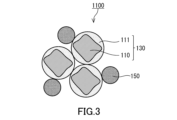
- FIG. 3 is a cross-sectional view showing another schematic configuration of the electrode material according to the first embodiment.
- FIG. 4 is a cross-sectional view showing a schematic configuration of a battery according to the second embodiment.
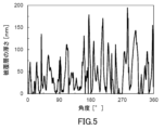
- FIG. 5 is a graph showing the measurement results of the thickness obtained for one particle of the coated active material according to Example 1.
- FIG. 6 is an electron microscope image of a cross section of the coated active material according to Example 1.
- FIG. 7 is an electron microscope image of a cross section of the coated active material according to Comparative Example 1.
- the solid electrolyte may be oxidized and decomposed during charging of the battery. This tendency is prominent when the solid electrolyte has poor oxidation stability, such as a sulfide solid electrolyte.
- the surface of the active material is coated with a coating material having excellent oxidation stability, such as a halide solid electrolyte.
- average means the arithmetic mean. Also, “average” means “calculate the arithmetic mean.”
- (Embodiment 1) 1 is a cross-sectional view showing a schematic configuration of an electrode material 1000 in embodiment 1.
- the electrode material 1000 includes a particle group of a coated active material 130.
- the particles of the coated active material 130 include an active material 110 and a coating layer 111.
- the active material 110 has a shape of, for example, a particle shape.
- the coating layer 111 coats at least a part of the surface of the active material 110.
- the coating layer 111 can be a layer containing a first solid electrolyte.
- the coating layer 111 is provided on the surface of the active material 110. By including the first solid electrolyte in the coating layer 111, the ionic conduction resistance of the coated active material 130 can be reduced.
- the first solid electrolyte contains, for example, Li, M, and F.
- M is at least one element selected from the group consisting of metal elements and semimetal elements other than Li.
- Si-metallic elements includes B, Si, Ge, As, Sb, and Te.
- Metal elements includes all elements in groups 1 to 12 of the periodic table except hydrogen, and all elements in groups 13 to 16 except B, Si, Ge, As, Sb, Te, C, N, P, O, S, and Se. In other words, metal elements are a group of elements that can become cations when they form inorganic compounds with halogen elements.
- the first solid electrolyte can be a solid electrolyte containing fluorine as an element.
- a solid electrolyte containing fluorine is also called a fluoride solid electrolyte.
- a fluoride solid electrolyte has excellent oxidation resistance due to the high electronegativity of fluorine. Therefore, by covering the surface of the active material 110 with the first solid electrolyte, it is possible to suppress the oxidative decomposition of other solid electrolytes in contact with the active material 110. This makes it possible to reduce the resistance of the battery.
- the resistance of a battery can be measured by the following method. After the battery is manufactured, it is placed in a thermostatic chamber at 25°C and subjected to a charge/discharge process. It is then charged to the desired charging voltage and discharged at the desired rate. It is then discharged at a constant current of the desired amount for several seconds.
- the resistance value is defined as the difference between the open circuit voltage before discharge and the voltage at the end of discharge divided by the amount of discharge current.
- the coating layer 111 may uniformly coat the active material 110.
- the coating layer 111 may cover only a portion of the surface of the active material 110.
- the particles of the active material 110 are in direct contact with each other through the portion not covered by the coating layer 111, improving the electronic conductivity between the particles of the active material 110.
- the battery can operate at high power.
- the electrode material 1000 satisfies at least one selected from the group consisting of the following requirements (i), (ii), and (iii).
- the thickness Tc of the coating layer calculated by averaging the median values in the thickness distribution of the coating layer of a plurality of the particles is 1.0 nm or more and 100.0 nm or less.
- the thickness Ta of the coating layer calculated by averaging the average values in the thickness distribution of the coating layer of a plurality of the particles is 9.0 nm or more and 100.0 nm or less.
- a thickness Tq of the coating layer calculated by averaging first quartiles in a thickness distribution of the coating layer of a plurality of the particles is 2.5 nm or more and 50.0 nm or less.
- a thickness distribution is obtained for each of the multiple particles of the coated active material 130.
- a median is calculated from this thickness distribution.
- the average value of the medians calculated for each of the multiple particles of the coated active material 130 is defined as Tc.
- Tc is 1.0 nm or more and 100.0 nm or less.
- a thickness distribution is obtained for each of the multiple particles of the coated active material 130.
- An average value is calculated from this thickness distribution.
- the average value calculated for each of the multiple particles of the coated active material 130 is defined as Ta.
- Ta is 9.0 nm or more and 100.0 nm or less.
- a thickness distribution is obtained for each of the multiple particles of the coated active material 130.
- the first quartile is calculated from this thickness distribution.
- the average value of the first quartiles calculated for each of the multiple particles of the coated active material 130 is defined as Tq. In this case, Tq is 2.5 nm or more and 50.0 nm or less.
- the thickness of the coating layer 111 can be measured, for example, by the following method.
- Figure 2 is a cross-sectional view of the coated active material 130 to explain the measurement position of the thickness of the coating layer 111.
- a cross-section of a particle of the coated active material 130 is photographed with a scanning electron microscope (SEM).
- SEM scanning electron microscope
- the center of gravity G of the active material 110 is found.
- line segments Ra and Rb are defined that pass through this center of gravity G and extend in the radial direction of the coated active material 130.
- the central angle ⁇ formed by the line segments Ra and Rb is 1°.
- a region r of the coated active material 130 bounded by the line segments Ra and Rb is defined. In this region r, the thickness R of the coating layer 111 is measured.
- the above measurement is repeated in the circumferential direction of the coated active material 130 to measure the thickness R for each region r. As a result, 360 thickness values can be obtained for one particle of the coated active material 130.
- the median, mean, and first quartile are calculated from the 360 thickness values of the coating layer 111 obtained from one particle of the coated active material 130, i.e., the thickness distribution.
- the median, mean, and first quartile are calculated for each of a plurality of any number of coated active material 130 particles using the method described above.
- Tc is calculated by averaging the median values obtained for each of the multiple particles of the coated active material 130.
- Ta is calculated by averaging the average values obtained for each of the multiple particles of the coated active material 130.
- Tq is calculated by averaging the first quartile values obtained for each of the multiple particles of the coated active material 130.
- the number of “any plurality of coated active material particles” is at least 4 or more.
- the number of “any plurality of coated active material particles” may be 10 or more, or may be 50 or more.
- the number of “any plurality of coated active material particles” may be 1000 or less, or may be 100 or less.
- the electrode material 1000 includes a coated active material 130, which includes an active material 110 and a coating layer 111. Since the coated active material 130 has the coating layer 111, the active material 110 is unlikely to come into direct contact with other materials. This makes it possible to suppress oxidative decomposition of the other materials.
- An example of the other material is the second solid electrolyte described below.
- the electrode material 1000 satisfies at least one selected from the group consisting of the above-mentioned requirements (i), (ii), and (iii). In this case, since the thickness distribution of the coating layer 111 is appropriately adjusted, it is possible to suppress direct contact between the active material 110 and other materials. In addition, since the thickness distribution of the coating layer 111 is appropriately adjusted, the coating layer 111 is unlikely to become a resistor, and the resistance of the battery can be reduced.
- Tc is greater than 100 nm
- Ta is greater than 100 nm
- Tq is greater than 50 nm
- the battery may become significantly more highly resistant, which is not preferable. This is mainly due to the following two reasons. First, if the surface of the active material is thickly coated with a coating layer that generally has low electronic conductivity, the electrons required for the electrode reaction may be difficult to supply to the active material, and the battery may become highly resistant. Also, if the ionic conductivity of the first solid electrolyte contained in the coating layer is not high, the ions required for the electrode reaction may be difficult to supply to the active material, and the battery may become highly resistant.
- Tc may be 30.0 nm or less, or 27.3 nm or less.
- Tc may be 10.0 nm or more, or 11.7 nm or more.
- the thickness of the coating layer 111 is sufficiently large to sufficiently suppress the oxidative decomposition of other materials. As a result, the resistance of the battery can be further reduced.
- Tc may be 11.8 nm or more and 20.0 nm or less, or 11.8 nm or more and 14.9 nm or less. In this case, the thickness distribution of the coating layer 111 is appropriately adjusted, so that the resistance of the battery can be further reduced.
- Ta may be 40.0 nm or less, or 38.8 nm or less.
- Ta may be 20.0 nm or more, or 21.1 nm or more.
- the thickness of the coating layer 111 is sufficiently large to sufficiently suppress the oxidative decomposition of other materials. As a result, the resistance of the battery can be further reduced.
- the coefficient of variation CV of the thickness of the coating layer 111 may be 70% or more and less than 237%. With this configuration, the variation in the thickness of the coating layer 111 can be reduced.
- the coefficient of variation CV means the value obtained by dividing the standard deviation by the mean value.
- a thickness distribution is obtained for each of the multiple particles of the coated active material 130.
- the mean value Xa is calculated from this thickness distribution.
- the standard deviation ⁇ a is calculated from this thickness distribution.
- the coefficient of variation CV is the average value of the coefficients of variation CVa obtained for each of the multiple particles of the coated active material 130, expressed as a percentage.
- the coefficient of variation CV may be 80% or more.
- the coefficient of variation CV may be 230% or less, 210% or less, 199% or less, or 150% or less. With this configuration, the variation in the thickness of the coating layer 111 can be further reduced.
- Tq may be 10.0 nm or less, or 9.1 nm or less.
- the active material 110 includes a material having the property of absorbing and releasing metal ions (e.g., lithium ions).
- the active material 110 is a positive electrode active material or a negative electrode active material.
- the electrode material 1000 is a positive electrode material.
- the electrode material 1000 is a negative electrode material.
- the active material 110 is a positive electrode active material
- a lithium-containing transition metal oxide, a transition metal fluoride, a polyanion material, a fluorinated polyanion material, a transition metal sulfide, a transition metal oxysulfide, a transition metal oxynitride, or the like may be used as the active material 110.
- the manufacturing cost of the battery can be reduced and the average discharge voltage can be increased.
- lithium-containing transition metal oxide examples include lithium nickel cobalt aluminum oxide (Li(NiCoAl)O 2 ), lithium nickel cobalt manganese oxide (Li(NiCoMn)O 2 ), and lithium cobalt oxide (LiCoO 2 ).
- the active material 110 is a negative electrode active material
- the materials described below can be used as the active material 110.
- the active material 110 has, for example, a particle shape.
- the particle shape of the active material 110 is not particularly limited.
- the particle shape of the active material 110 can be spherical, oval spherical, scaly, or fibrous.
- the median diameter of the active material 110 may be 0.1 ⁇ m or more and 100 ⁇ m or less.
- the median diameter of the active material 110 is 0.1 ⁇ m or more, the coated active material 130 and the other solid electrolyte can form a good dispersion state. As a result, the charge and discharge characteristics of the battery are improved.
- the median diameter of the active material 110 is 100 ⁇ m or less, the diffusion speed of lithium inside the active material 110 is sufficiently ensured. Therefore, the battery can operate at high output.
- volume diameter refers to the particle size when the cumulative volume in the volume-based particle size distribution is equal to 50%.
- the volume-based particle size distribution is measured, for example, by a laser diffraction measuring device or an image analyzer.
- the coating layer 111 may include a first solid electrolyte.
- the first solid electrolyte has ion conductivity.
- the ion conductivity is typically lithium ion conductivity.
- the coating layer 111 may include the first solid electrolyte as a main component, or may include only the first solid electrolyte.
- the "main component” means a component that is included most in mass ratio.
- “Includes only the first solid electrolyte” means that, except for unavoidable impurities, materials other than the first solid electrolyte are not intentionally added.
- the mass ratio of the unavoidable impurities to the total mass of the coating layer 111 may be 5% or less, 3% or less, 1% or less, or 0.5% or less.
- the first solid electrolyte may be a material containing Li, M, and F.
- M is at least one selected from the group consisting of metal elements and semimetal elements other than Li. Such a material has excellent oxidation resistance. Therefore, the coated active material 130 having the coating layer 111 of the first solid electrolyte can improve the charge/discharge efficiency and thermal stability of the battery.
- the first solid electrolyte may contain Li, M1, M2, and F.
- M1 is at least one selected from the group consisting of Ti and Zr
- M2 is at least one selected from the group consisting of Al, Y, Mg, and Ca.
- high lithium ion conductivity is, for example, 1.0 ⁇ 10 ⁇ 8 S/cm or more. That is, the first solid electrolyte may have a lithium ion conductivity of, for example, 1.0 ⁇ 10 ⁇ 8 S/cm or more.
- the first solid electrolyte may form a cationic framework structure suitable for lithium ion conduction in the crystal lattice. Therefore, the first solid electrolyte exhibits high lithium ion conductivity.
- M2 may be Al to further increase the ionic conductivity of the first solid electrolyte.
- M1 may be Ti.
- M2 may be Al and M1 may be Ti.
- the first solid electrolyte may consist essentially of Li, Ti, Al, and F.
- the first solid electrolyte consists essentially of Li, Ti, Al, and F
- the molar ratio (i.e., molar fraction) of the total amount of substance of Li, Ti, Al, and F to the total amount of substance of all elements constituting the first solid electrolyte is 90% or more.
- the molar ratio (i.e., molar fraction) may be 95% or more.
- the first solid electrolyte may consist only of Li, Ti, Al, and F.
- composition of the first solid electrolyte may be represented by the following composition formula (1):
- M3 is at least one selected from the group consisting of Zr, Ni, Fe, and Cr, m is the valence of M3, and 0.1 ⁇ x ⁇ 0.9, 0 ⁇ y ⁇ 0.1, 0 ⁇ z ⁇ 0.1, and 0.8 ⁇ b ⁇ 1.2 are satisfied.
- a first solid electrolyte having such a composition has higher ionic conductivity and can be produced by a method with high industrial productivity.
- the first solid electrolyte has a higher ionic conductivity.
- composition formula (1) 0.1 ⁇ x ⁇ 0.7 may be satisfied.
- the upper and lower limits of the range of x in composition formula (1) can be defined by any combination selected from the following values: 0.1, 0.3, 0.4, 0.5, 0.6, 0.65, 0.67, 0.7, 0.8, and 0.9.
- composition formula (1) can be defined by any combination selected from the numerical values of 0.8, 0.9, 0.94, 1.0, 1.06, 1.1, and 1.2.
- the first solid electrolyte may be crystalline or amorphous.
- the shape of the first solid electrolyte is not limited.
- the shape of the first solid electrolyte is, for example, needle-like, spherical, or elliptical.
- the shape of the first solid electrolyte may be particulate.
- the first solid electrolyte When the shape of the first solid electrolyte is, for example, particulate (e.g., spherical), the first solid electrolyte may have a median diameter of 0.01 ⁇ m or more and 100 ⁇ m or less.
- the first solid electrolyte according to the first embodiment can be produced, for example, by the following method.
- Two or more types of raw material powders are mixed to achieve the desired composition.
- the desired composition is Li2.7Ti0.3Al0.7F6 .
- the raw material powders may be mixed in a pre-adjusted molar ratio to offset composition changes that may occur in the synthesis process.
- the raw powders are reacted mechanochemically with each other in a mixing device such as a planetary ball mill to obtain a reactant. That is, the raw powders are mixed and reacted using the method of mechanochemical milling.
- the reactant thus obtained may be further calcined in an inert gas atmosphere or in vacuum.
- the mixture of raw material powders may be fired in an inert gas atmosphere to react with each other and obtain reactants.
- inert gases are helium, nitrogen, or argon.
- the firing may be performed in a vacuum.
- the mixture of raw material powders may be placed in a container (e.g., a crucible, a sealed container, and a vacuum sealed tube) and fired in a heating furnace.
- the first solid electrolyte according to embodiment 1 is obtained.
- composition of the solid electrolyte can be determined, for example, by inductively coupled plasma optical emission spectroscopy or ion chromatography.
- the coated active material can be produced, for example, by the following method.
- a powder of the active material 110 and a powder of the first solid electrolyte are prepared in a predetermined mass ratio.
- a powder of Li(Ni,Co,Al) O2 is prepared as the active material 110
- a powder of Li2.7Al0.7Ti0.3F6 is prepared as the first solid electrolyte.
- the mixture Before mechanical energy is applied to the mixture of the active material 110 powder and the first solid electrolyte powder, the mixture may be milled.
- a mixing device such as a ball mill may be used for the milling process.
- the milling process may be performed in a dry or inert atmosphere.
- the coated active material may be manufactured by a dry particle composite method.
- the process by the dry particle composite method includes applying at least one mechanical energy selected from the group consisting of impact, compression, and shear to the active material 110 and the first solid electrolyte.
- the active material 110 and the first solid electrolyte are mixed in an appropriate ratio.
- the equipment used in the manufacture of the coated active material is not limited, and may be an equipment capable of applying mechanical energy such as impact, compression, or shear to the mixture of the active material 110 and the first solid electrolyte.
- equipment capable of applying mechanical energy include ball mills, jet mills, compression shear processing equipment (particle composite equipment) such as "Mechanofusion” (manufactured by Hosokawa Micron Corporation) and “Nobilta” (manufactured by Hosokawa Micron Corporation), high-speed mixer granulators such as "Balance Gran” (manufactured by Freund Turbo Corporation), and "Hybridization System (high-velocity air current impact equipment)” (manufactured by Nara Machinery Works, Ltd.).
- Mechanisms is a particle compounding device that uses dry mechanical compounding technology by applying strong mechanical energy to particles of multiple different materials.
- mechanofusion the powdered raw materials are fed between a rotating container and a press head, and mechanical energy such as compression, shear, and friction is applied to them, causing the particles to compound.
- Nobilta is a particle compounding device that uses dry mechanical compounding technology, an advanced form of particle compounding technology, to compound nanoparticles as raw materials. Nobilta produces composite particles by applying mechanical energy in the form of impact, compression, and shear to multiple raw material powders.
- Nobilta a rotor that is positioned so as to have a specified gap between itself and the inner wall of a horizontal cylindrical mixing vessel rotates at high speed, and the process of forcing the raw material powder to pass through the gap is repeated multiple times. This applies impact, compression, and shear forces to the mixture, making it possible to produce composite particles of active material 110 and the first solid electrolyte. Conditions such as the rotor rotation speed, processing time, and loading amount can be adjusted as appropriate.
- the Balance Gran has a chopper that stirs the powder in a spiral motion from the outer periphery to the inner periphery, promoting convection, and is also equipped with an agitator scraper that rotates in the opposite direction to the chopper. These actions enable the mixture to be uniformly dispersed to produce composite particles.
- raw powder is dispersed in a high-speed air stream while a force consisting mainly of an impact is applied. This produces composite particles of the active material 110 and the first solid electrolyte.
- the coated active material 130 may be produced by mixing the active material 110 and the first solid electrolyte using a mortar, mixer, or the like.
- the first solid electrolyte may be deposited on the surface of the active material 110 by various methods, such as a spray method, a spray-dry coating method, an electrodeposition method, an immersion method, or a mechanical mixing method using a disperser.
- Tc, Ta, and Tq can be adjusted to the desired range by appropriately adjusting the mixing ratio of the active material 110 and the first solid electrolyte when producing the coated active material 130.
- Tc, Ta, and Tq can be adjusted to the desired range by appropriately adjusting the mechanical energy such as impact, compression, and shear.
- FIG. 3 is a cross-sectional view showing another schematic configuration of the electrode material 1100 in the first embodiment.
- the electrode material 1100 includes a particle group of the coated active material 130 and a second solid electrolyte 150.
- the electrode material 1100 of the present embodiment is suitable for reducing the resistance of a battery.
- the active material 110 contained in the coated active material 130 is separated from the second solid electrolyte 150 by the coating layer 111.
- the active material 110 does not need to be in direct contact with the second solid electrolyte 150. This is because the coating layer 111 has ion conductivity.
- the second solid electrolyte 150 may be a solid electrolyte having a different composition from the first solid electrolyte.
- the first solid electrolyte and the second solid electrolyte 150 may be different materials.
- the electrode material 1100 contains the coated active material 130, which is suitable for suppressing an increase in the resistance of the battery.
- the second solid electrolyte 150 may include at least one selected from the group consisting of a halide solid electrolyte, a sulfide solid electrolyte, an oxide solid electrolyte, a polymer solid electrolyte, and a complex hydride solid electrolyte.
- examples of the halide solid electrolyte that can be used include Li3REX6 , Li3 (Al,Ga,In) X6 , Li2MgX4 , Li2FeX4 , Li(Al,Ga,In) X4 , and LiI, where X is at least one selected from the group consisting of Cl, Br, and I, and RE is at least one selected from the group consisting of rare earth elements.
- the oxide solid electrolyte 150 is an oxide solid electrolyte
- examples of the oxide solid electrolyte that can be used include NASICON-type solid electrolytes represented by LiTi2 ( PO4 ) 3 and its elemental substitution products , (LaLi) TiO3 -based perovskite-type solid electrolytes, LISICON-type solid electrolytes represented by Li14ZnGe4O16 , Li4SiO4 , LiGeO4 and their elemental substitution products, garnet-type solid electrolytes represented by Li7La3Zr2O12 and its elemental substitution products, Li3N and its H -substitution products, Li3PO4 and its N-substitution products , and glasses and glass ceramics based on Li- B - O compounds such as LiBO2 and Li3BO3 to which materials such as Li2SO4 and Li2CO3 have been added.
- the second solid electrolyte 150 is a polymer solid electrolyte
- a compound of a polymer compound and a lithium salt can be used as the polymer solid electrolyte.
- the polymer compound may have an ethylene oxide structure. By having an ethylene oxide structure, the polymer compound can contain a large amount of lithium salt. Therefore, the ion conductivity can be further increased.
- lithium salt LiPF 6 , LiBF 4 , LiSbF 6 , LiAsF 6 , LiSO 3 CF 3 , LiN (SO 2 CF 3 ) 2 , LiN (SO 2 C 2 F 5 ) 2 , LiN (SO 2 CF 3 ) (SO 2 C 4 F 9 ), LiC (SO 2 CF 3 ) 3 , etc.
- LiPF 6 , LiBF 4 , LiSbF 6 , LiAsF 6 , LiSO 3 CF 3 , LiN (SO 2 CF 3 ) 2 , LiN (SO 2 C 2 F 5 ) 2 , LiN (SO 2 CF 3 ) (SO 2 C 4 F 9 ), LiC (SO 2 CF 3 ) 3 , etc. can be used.
- the lithium salt one type of lithium salt selected from these may be used alone, or a mixture of two or more types of lithium salts selected from these may be used.
- the second solid electrolyte 150 is a complex hydride solid electrolyte, for example, LiBH 4 --LiI, LiBH 4 --P 2 S 5 , or the like can be used as the complex hydride solid electrolyte.
- the second solid electrolyte 150 may contain Li and S.
- the second solid electrolyte 150 may contain a sulfide solid electrolyte.
- the sulfide solid electrolyte has high ionic conductivity and can improve the charge/discharge efficiency of the battery.
- the sulfide solid electrolyte may have poor oxidation resistance.
- Li2S - P2S5 Li2S - SiS2 , Li2S- B2S3 , Li2S - GeS2 , Li3.25Ge0.25P0.75S4 , Li10GeP2S12 , and the like can be used as the sulfide solid electrolyte.
- LiX, Li2O , MOq , LipMOq , and the like may be added to these.
- the element X in " LiX " is at least one element selected from the group consisting of F , Cl , Br , and I.
- the element M in "MO q " and " LipMO q " is at least one element selected from the group consisting of P, Si, Ge, B, Al, Ga, In, Fe, and Zn.
- Each of p and q in “MO q “ and “ LipMO q " is an independent natural number.
- the second solid electrolyte 150 may contain two or more materials selected from the materials listed as solid electrolytes.
- the second solid electrolyte 150 may contain, for example, a halide solid electrolyte and a sulfide solid electrolyte.
- the second solid electrolyte 150 may contain unavoidable impurities such as starting materials, by-products, and decomposition products used in synthesizing the solid electrolyte.
- the shape of the second solid electrolyte is not particularly limited and may be needle-like, spherical, elliptical, or the like.
- the shape of the second solid electrolyte 150 may be particulate.
- the solid electrolyte 150 When the second solid electrolyte 150 has a particulate (e.g., spherical) shape, the solid electrolyte may have a median diameter of 0.1 ⁇ m or more and 100 ⁇ m or less. When the solid electrolyte has a median diameter in this range, the coated active material 130 and the second solid electrolyte 150 are well dispersed in the electrode material 1100.
- a particulate e.g., spherical
- the median diameter of the second solid electrolyte 150 may be 10 ⁇ m or less. In this case, the dispersion state of the coated active material 130 and the second solid electrolyte 150 in the electrode material 1100 becomes better.
- the median diameter of the second solid electrolyte 150 may be smaller than the median diameter of the coated active material 130. In this case, the dispersion state of the coated active material 130 and the second solid electrolyte 150 in the electrode material 1100 becomes better.
- the second solid electrolyte 150 and the coated active material 130 may be in contact with each other.
- the coating layer 111 and the second solid electrolyte 150 are in contact with each other.
- the electrode material 1100 may contain a plurality of particles of the second solid electrolyte 150 and a plurality of particles of the coated active material 130.
- the electrode material 1100 may be a mixed powder of a powder of the coated active material 130 and a powder of the second solid electrolyte 150.
- the content of the second solid electrolyte 150 and the content of the coated active material 130 may be the same or different.
- the electrode material 1000 or the electrode material 1100 may contain a binder for the purpose of improving the adhesion between particles.
- the binder is used to improve the binding property of the material constituting the electrode.
- the binder include polyvinylidene fluoride, polytetrafluoroethylene, polyethylene, polypropylene, aramid resin, polyamide, polyimide, polyamideimide, polyacrylonitrile, polyacrylic acid, polyacrylic acid methyl ester, polyacrylic acid ethyl ester, polyacrylic acid hexyl ester, polymethacrylic acid, polymethacrylic acid methyl ester, polymethacrylic acid ethyl ester, polymethacrylic acid hexyl ester, polyvinyl acetate, polyvinylpyrrolidone, polyether, polycarbonate, polyethersulfone, polyetherketone, polyetheretherketone, polyphenylene sulfide, hexafluoropolypropylene,
- One selected from these may be used alone, or two or more may be used in combination.
- the binder may be an elastomer because of its excellent binding properties.
- An elastomer is a polymer that has rubber elasticity.
- the elastomer used as the binder may be a thermoplastic elastomer or a thermosetting elastomer.
- the binder may contain a thermoplastic elastomer.
- thermoplastic elastomers examples include styrene-ethylene-butylene-styrene (SEBS), styrene-ethylene-propylene-styrene (SEPS), styrene-ethylene-ethylene-propylene-styrene (SEEPS), butylene rubber (BR), isoprene rubber (IR), chloroprene rubber (CR), acrylonitrile-butadiene rubber (NBR), styrene-butylene rubber (SBR), styrene-butadiene-styrene (SBS), styrene-isoprene-styrene (SIS), hydrogenated isoprene rubber (HIR), hydrogenated butyl rubber (HIIR), hydrogenated nitrile rubber (HNBR), hydrogenated styrene-butylene rubber (HSBR), polyvinylidene fluoride (PVdF), polytetrafluoroethylene (PTFE), etc.
- the electrode material 1000 or the electrode material 1100 may contain a conductive assistant for the purpose of increasing electronic conductivity.
- the conductive assistant that can be used include graphites such as natural graphite or artificial graphite, carbon blacks such as acetylene black and ketjen black, conductive fibers such as carbon fibers and metal fibers, metal powders such as carbon fluoride and aluminum, conductive whiskers such as zinc oxide and potassium titanate, conductive metal oxides such as titanium oxide, and conductive polymer compounds such as polyaniline, polypyrrole, and polythiophene.
- the electrode material 1100 is obtained by mixing the particle group of the coated active material 130 and the second solid electrolyte 150.
- the method of mixing the particle group of the coated active material 130 and the second solid electrolyte 150 is not limited.
- the particle group of the coated active material 130 and the second solid electrolyte 150 may be mixed using a tool such as a mortar, or the particle group of the coated active material 130 and the second solid electrolyte 150 may be mixed using a mixing device such as a ball mill.
- the battery in embodiment 2 includes a first electrode, a separator portion, and a second electrode.
- the separator portion is located between the first electrode and the second electrode.
- the first electrode includes the electrode material 1000 in embodiment 1.
- the first electrode may include the electrode material 1100.
- the first electrode is an electrode having the opposite polarity to the second electrode. If the first electrode is positive, the second electrode is negative. If the first electrode is negative, the second electrode is positive.
- the separator portion may be an electrolyte layer containing a solid electrolyte, or a separator impregnated with an electrolyte solution.
- FIG. 4 is a cross-sectional view showing a schematic configuration of a battery 2000 according to embodiment 2.
- the battery 2000 includes a positive electrode 201, an electrolyte layer 202, and a negative electrode 203.
- the electrolyte layer 202 is disposed between the positive electrode 201 and the negative electrode 203.
- the separator portion is the electrolyte layer 32.
- the positive electrode 201 includes the electrode material 1000 described in embodiment 1.
- the positive electrode 201 may include the electrode material 1100. With this configuration, an increase in the resistance of the battery 2000 can be suppressed, and a battery with excellent durability can be provided.
- the negative electrode 203 may include the electrode material 1000 or 1100.
- the thickness of each of the positive electrode 201 and the negative electrode 203 may be 10 ⁇ m or more and 500 ⁇ m or less. When the thickness of the positive electrode 201 and the negative electrode 203 is 10 ⁇ m or more, sufficient energy density of the battery can be ensured. When the thickness of the positive electrode 201 and the negative electrode 203 is 500 ⁇ m or less, high-output operation of the battery 2000 can be achieved.
- the electrolyte layer 202 is a layer containing an electrolyte material.
- the electrolyte layer 202 may contain at least one solid electrolyte selected from the group consisting of a sulfide solid electrolyte, an oxide solid electrolyte, a halide solid electrolyte, a polymer solid electrolyte, and a complex hydride solid electrolyte. Details of each solid electrolyte are as described in the first embodiment.
- the thickness of the electrolyte layer 202 may be 1 ⁇ m or more and 300 ⁇ m or less. When the thickness of the electrolyte layer 202 is 1 ⁇ m or more, the positive electrode 201 and the negative electrode 203 can be more reliably separated. When the thickness of the electrolyte layer 202 is 300 ⁇ m or less, the battery 2000 can be operated at high output.
- the negative electrode 203 contains a material as the negative electrode active material that has the property of absorbing and releasing metal ions (e.g., lithium ions).
- metal ions e.g., lithium ions
- metal materials, carbon materials, oxides, nitrides, tin compounds, silicon compounds, etc. can be used as the negative electrode active material.
- the metal material may be a single metal.
- the metal material may be an alloy.
- Examples of the metal material include lithium metal and lithium alloys.
- Examples of the carbon material include natural graphite, coke, partially graphitized carbon, carbon fiber, spherical carbon, artificial graphite, and amorphous carbon. From the viewpoint of capacity density, silicon (Si), tin (Sn), silicon compounds, tin compounds, etc. can be preferably used.
- the median diameter of the particles of the negative electrode active material may be 0.1 ⁇ m or more and 100 ⁇ m or less.
- the negative electrode 203 may contain other materials, such as a solid electrolyte.
- the material described in embodiment 1 can be used as the solid electrolyte.
- the battery 2000 can be configured as a battery of various shapes, such as a coin type, a cylindrical type, a square type, a sheet type, a button type, a flat type, a laminated type, etc.
- An electrode material including a particle group of a coated active material The coated active material particles include an active material and a coating layer that coats at least a portion of a surface of the active material, An electrode material that satisfies at least one selected from the group consisting of the following requirements (i), (ii), and (iii): (i) The thickness Tc of the coating layer calculated by averaging the median values in the thickness distribution of the coating layer of a plurality of the particles is 1.0 nm or more and 100.0 nm or less. (ii) The thickness Ta of the coating layer calculated by averaging the average values in the thickness distribution of the coating layer of a plurality of the particles is 9.0 nm or more and 100.0 nm or less. (iii) a thickness Tq of the coating layer calculated by averaging first quartiles in a thickness distribution of the coating layer of a plurality of the particles is 2.5 nm or more and 50.0 nm or less.
- the electrode material of Technology 1 can reduce the resistance of the battery.
- the electrode material according to the first or second aspect of the present invention has a Tc of 10.0 nm or more. According to this configuration, the thickness of the coating layer is sufficiently large, so that the oxidative decomposition of other materials can be sufficiently suppressed. As a result, the resistance of the battery can be further reduced.
- the first solid electrolyte has higher ionic conductivity and can be produced by a method with high industrial productivity.
- the electrode material includes a coated active material, and is therefore suitable for suppressing an increase in the resistance of a battery.
- the battery of Technology 19 suppresses the increase in battery resistance, improving the durability of the battery.
- a first electrode comprising the electrode material according to any one of claims 1 to 18; A second electrode; an electrolyte layer disposed between the first electrode and the second electrode; Equipped with a battery.
- the battery of Technology 20 suppresses the increase in battery resistance, improving the durability of the battery.
- Example 1 [Preparation of first solid electrolyte]
- the obtained mixed powder was milled at 500 rpm for 12 hours using a planetary ball mill (Fritsch, P-7 type). In this way, a powder of a halide solid electrolyte material according to Example 1 was obtained.
- the solid electrolyte material according to Example 1 had a composition represented by Li 2.7 Ti 0.3 Al 0.7 F 6 (hereinafter referred to as "LTAF").
- NCA Li(NiCoAl)O 2
- LTAF-coated NCA a coated active material having a coating layer made of LTAF on the surface of the NCA
- the coating layer was formed using a high-speed mixer granulator (BG-2L, manufactured by Freund Turbo). Specifically, NCA and LTAF were weighed to have a weight ratio of 95.94:4.06, and were put into the high-speed mixer granulator, and treated under the conditions of chopper rotation speed: 3000 rpm, treatment time: 60 minutes.
- Example 2 In preparing the coated active material, NCA and LTAF were weighed out to have a weight ratio of 96.52:3.48. Except for this, the positive electrode material of Example 2 was prepared in the same manner as in Example 1.
- Example 3 In preparing the coated active material, NCA and LTAF were weighed out to have a weight ratio of 97.31:2.69. Except for this, the positive electrode material of Example 3 was prepared in the same manner as in Example 1.
- Example 4 In the preparation of the coated active material, NCA and LTAF were weighed out to have a weight ratio of 97.31:2.69, and charged into a high-speed mixer granulator, and treated under the conditions of chopper rotation speed: 3000 rpm, treatment time: 80 minutes. Otherwise, the positive electrode material of Example 4 was prepared in the same manner as in Example 1.
- Example 5 In the preparation of the coated active material, NCA and LTAF were weighed out to have a weight ratio of 97.31:2.69, and charged into a high-speed mixer granulator, and treated under the conditions of chopper rotation speed: 3000 rpm, treatment time: 20 minutes. Otherwise, the positive electrode material of Example 5 was prepared in the same manner as in Example 1.
- Example 6 In preparing the coated active material, NCA and LTAF were weighed out to have a weight ratio of 98.26:1.74. Except for this, the positive electrode material of Example 6 was prepared in the same manner as in Example 1.
- Comparative Example 1 In preparing the coated active material, NCA and LTAF were weighed out to have a weight ratio of 98.84:1.16. A positive electrode material of Comparative Example 1 was prepared in the same manner as in Example 1.
- Tc was calculated by averaging the median values obtained for each of the four particles of coated active material.
- Ta was calculated by averaging the average values obtained for each of the four particles of coated active material.
- Tq was calculated by averaging the first quartiles obtained for each of the four particles of coated active material. The results are shown in Table 1.
- the average value Xa and standard deviation ⁇ a were calculated from the thickness distribution obtained for each of the four particles of the coated active material.
- the coefficient of variation CV of the thickness of the coating layer was calculated by averaging the coefficients of variation CVa calculated for each of the four particles of the coated active material and calculating the average value as a percentage. The results are shown in Table 1.
- FIG. 5 is a graph showing the results of thickness measurements obtained for one particle of the coated active material of Example 1.
- FIG. 5 shows the thickness distribution obtained for one particle of the coated active material of Example 1.
- the horizontal axis shows the angle [°] in the circumferential direction of the particle of the coated active material on a circumference centered on the center of gravity of the positive electrode active material.
- the vertical axis shows the thickness [nm] of the coating layer at each angle.
- FIG. 6 is an electron microscope image of a cross section of the coated active material of Example 1.
- the coated active material 130 of Example 1 had a positive electrode active material 110 and a coating layer 111.
- the coated active material 130 of Example 1 was placed on a support 200 for cross-sectional observation.
- the coating layer 111 coated at least a portion of the surface of the positive electrode active material 110.
- the coating layer 111 had an appropriate thickness.
- a coating layer 111 with a smaller coefficient of variation was formed than in Comparative Example 1 described below.
- Figure 7 is an electron microscope image of a cross section of the coated active material of Comparative Example 1. As shown in Figure 7, in Comparative Example 1, there were many areas where the coating layer 111 was thin. In addition, in Comparative Example 1, a coating layer 111 with a larger coefficient of variation was formed than in Example 1.
- the positive electrode material was weighed so that it contained 5 mg of NCA.
- the LPS and the positive electrode material were laminated in this order inside an insulating outer cylinder.
- the resulting laminate was pressure-molded at a pressure of 720 MPa.
- metallic lithium was placed so as to be in contact with the LPS layer, and pressure-molded again at a pressure of 40 MPa.
- stainless steel current collectors were placed above and below the laminate. Current collector leads were attached to each current collector.
- the inside of the outer cylinder was sealed using an insulating ferrule to isolate the inside of the outer cylinder from the outside atmosphere.
- the batteries of Examples 1 to 5 and Comparative Example 1 were produced.
- the battery was restrained from above and below with four bolts, and a surface pressure of 150 MPa was applied to the battery.
- the battery was placed in a thermostatic chamber at 25°C. The battery was charged at a constant current of 50 ⁇ A until the voltage reached 4.25 V. The battery was then discharged at a constant current of 50 ⁇ A until the voltage reached 3.68 V. The battery was then discharged at a constant current of 46.4 mA for 2 seconds. The resistance of the battery was calculated by dividing the difference between the open circuit voltage before discharge and the voltage at the end of discharge by the discharge current. The results are shown in Table 1.
- the thickness of the coating layer was in a range that was neither too thin nor too thick. For this reason, it is presumed that the oxidative decomposition of the second solid electrolyte was suppressed. As a result, the battery resistance of Examples 1 to 6 was lower than that of Comparative Example 1.
- the coating layer containing LTAF has an ion conductivity of 1/1000 or less compared to that of LPS.
- the technology disclosed herein is useful, for example, in all-solid-state lithium-ion secondary batteries.
Landscapes
- Chemical & Material Sciences (AREA)
- Chemical Kinetics & Catalysis (AREA)
- Electrochemistry (AREA)
- General Chemical & Material Sciences (AREA)
- Inorganic Chemistry (AREA)
- Engineering & Computer Science (AREA)
- Composite Materials (AREA)
- Materials Engineering (AREA)
- Manufacturing & Machinery (AREA)
- Organic Chemistry (AREA)
- Crystallography & Structural Chemistry (AREA)
- General Life Sciences & Earth Sciences (AREA)
- Life Sciences & Earth Sciences (AREA)
- Environmental & Geological Engineering (AREA)
- Geology (AREA)
- General Physics & Mathematics (AREA)
- Condensed Matter Physics & Semiconductors (AREA)
- Physics & Mathematics (AREA)
- Secondary Cells (AREA)
- Battery Electrode And Active Subsutance (AREA)
Priority Applications (4)
| Application Number | Priority Date | Filing Date | Title |
|---|---|---|---|
| CN202480034954.6A CN121195358A (zh) | 2023-06-21 | 2024-05-10 | 电极材料以及电池 |
| JP2025527559A JPWO2024262184A1 (https=) | 2023-06-21 | 2024-05-10 | |
| EP24825593.7A EP4734182A1 (en) | 2023-06-21 | 2024-05-10 | Electrode material and battery |
| US19/421,079 US20260106151A1 (en) | 2023-06-21 | 2025-12-16 | Electrode material and battery |
Applications Claiming Priority (2)
| Application Number | Priority Date | Filing Date | Title |
|---|---|---|---|
| JP2023101895 | 2023-06-21 | ||
| JP2023-101895 | 2023-06-21 |
Related Child Applications (1)
| Application Number | Title | Priority Date | Filing Date |
|---|---|---|---|
| US19/421,079 Continuation US20260106151A1 (en) | 2023-06-21 | 2025-12-16 | Electrode material and battery |
Publications (1)
| Publication Number | Publication Date |
|---|---|
| WO2024262184A1 true WO2024262184A1 (ja) | 2024-12-26 |
Family
ID=93935621
Family Applications (1)
| Application Number | Title | Priority Date | Filing Date |
|---|---|---|---|
| PCT/JP2024/017533 Ceased WO2024262184A1 (ja) | 2023-06-21 | 2024-05-10 | 電極材料、および、電池 |
Country Status (5)
| Country | Link |
|---|---|
| US (1) | US20260106151A1 (https=) |
| EP (1) | EP4734182A1 (https=) |
| JP (1) | JPWO2024262184A1 (https=) |
| CN (1) | CN121195358A (https=) |
| WO (1) | WO2024262184A1 (https=) |
Citations (3)
| Publication number | Priority date | Publication date | Assignee | Title |
|---|---|---|---|---|
| JP2014011028A (ja) * | 2012-06-29 | 2014-01-20 | Toyota Motor Corp | 複合活物質、固体電池および複合活物質の製造方法 |
| WO2021161752A1 (ja) * | 2020-02-14 | 2021-08-19 | パナソニックIpマネジメント株式会社 | 被覆正極活物質、正極材料、電池、および被覆正極活物質の製造方法 |
| WO2021187391A1 (ja) | 2020-03-18 | 2021-09-23 | パナソニックIpマネジメント株式会社 | 正極材料、および、電池 |
-
2024
- 2024-05-10 JP JP2025527559A patent/JPWO2024262184A1/ja active Pending
- 2024-05-10 EP EP24825593.7A patent/EP4734182A1/en active Pending
- 2024-05-10 CN CN202480034954.6A patent/CN121195358A/zh active Pending
- 2024-05-10 WO PCT/JP2024/017533 patent/WO2024262184A1/ja not_active Ceased
-
2025
- 2025-12-16 US US19/421,079 patent/US20260106151A1/en active Pending
Patent Citations (3)
| Publication number | Priority date | Publication date | Assignee | Title |
|---|---|---|---|---|
| JP2014011028A (ja) * | 2012-06-29 | 2014-01-20 | Toyota Motor Corp | 複合活物質、固体電池および複合活物質の製造方法 |
| WO2021161752A1 (ja) * | 2020-02-14 | 2021-08-19 | パナソニックIpマネジメント株式会社 | 被覆正極活物質、正極材料、電池、および被覆正極活物質の製造方法 |
| WO2021187391A1 (ja) | 2020-03-18 | 2021-09-23 | パナソニックIpマネジメント株式会社 | 正極材料、および、電池 |
Also Published As
| Publication number | Publication date |
|---|---|
| JPWO2024262184A1 (https=) | 2024-12-26 |
| EP4734182A1 (en) | 2026-04-29 |
| CN121195358A (zh) | 2025-12-23 |
| US20260106151A1 (en) | 2026-04-16 |
Similar Documents
| Publication | Publication Date | Title |
|---|---|---|
| JP7493157B2 (ja) | イオン伝導体材料および電池 | |
| WO2023037817A1 (ja) | 被覆活物質、電極材料および電池 | |
| WO2022209686A1 (ja) | 被覆正極活物質、正極材料、電池、および被覆正極活物質の製造方法 | |
| WO2022224505A1 (ja) | 正極材料および電池 | |
| US20240194862A1 (en) | Positive electrode material, positive electrode, and battery | |
| JP7796340B2 (ja) | 被覆活物質、正極材料、正極および電池 | |
| WO2022244416A1 (ja) | 複合正極活物質、正極材料、および電池 | |
| WO2023037769A1 (ja) | 正極材料、正極および電池 | |
| JP7843472B2 (ja) | 被覆活物質、正極材料、正極および電池 | |
| WO2022255027A1 (ja) | 被覆活物質、正極材料、正極および電池 | |
| JP7796351B2 (ja) | 被覆活物質、電極材料および電池 | |
| JP7788681B2 (ja) | 被覆活物質、電極材料および電池 | |
| WO2023139897A1 (ja) | 電池 | |
| WO2023037815A1 (ja) | 被覆活物質、電極材料および電池 | |
| WO2023037816A1 (ja) | 被覆活物質、電極材料および電池 | |
| WO2024262184A1 (ja) | 電極材料、および、電池 | |
| US20260128324A1 (en) | Coated active material, positive electrode material, positive electrode, and battery | |
| WO2024262185A1 (ja) | 被覆活物質、正極材料、正極、および電池 | |
| JP7825185B2 (ja) | 正極材料、正極および電池 | |
| US20260005294A1 (en) | Positive electrode material, positive electrode, and battery | |
| WO2024262182A1 (ja) | 被覆活物質、正極材料、および電池 | |
| WO2025253965A1 (ja) | 電極材料、および電池 | |
| WO2025253964A1 (ja) | 被覆活物質、電極材料、および電池 | |
| WO2024262183A1 (ja) | 被覆活物質、正極材料、および電池 | |
| US20260128289A1 (en) | Coated active material, positive electrode material, and battery |
Legal Events
| Date | Code | Title | Description |
|---|---|---|---|
| 121 | Ep: the epo has been informed by wipo that ep was designated in this application |
Ref document number: 24825593 Country of ref document: EP Kind code of ref document: A1 |
|
| ENP | Entry into the national phase |
Ref document number: 2025527559 Country of ref document: JP Kind code of ref document: A |
|
| WWE | Wipo information: entry into national phase |
Ref document number: 2025527559 Country of ref document: JP |
|
| WWE | Wipo information: entry into national phase |
Ref document number: 2024825593 Country of ref document: EP |
|
| NENP | Non-entry into the national phase |
Ref country code: DE |
|
| ENP | Entry into the national phase |
Ref document number: 2024825593 Country of ref document: EP Effective date: 20260121 |
|
| ENP | Entry into the national phase |
Ref document number: 2024825593 Country of ref document: EP Effective date: 20260121 |
|
| ENP | Entry into the national phase |
Ref document number: 2024825593 Country of ref document: EP Effective date: 20260121 |