WO2024262016A1 - エレベーター - Google Patents
エレベーター Download PDFInfo
- Publication number
- WO2024262016A1 WO2024262016A1 PCT/JP2023/023351 JP2023023351W WO2024262016A1 WO 2024262016 A1 WO2024262016 A1 WO 2024262016A1 JP 2023023351 W JP2023023351 W JP 2023023351W WO 2024262016 A1 WO2024262016 A1 WO 2024262016A1
- Authority
- WO
- WIPO (PCT)
- Prior art keywords
- detection body
- elevator
- car
- suppression member
- vibration
- Prior art date
- Legal status (The legal status is an assumption and is not a legal conclusion. Google has not performed a legal analysis and makes no representation as to the accuracy of the status listed.)
- Ceased
Links
Images


Classifications
-
- B—PERFORMING OPERATIONS; TRANSPORTING
- B66—HOISTING; LIFTING; HAULING
- B66B—ELEVATORS; ESCALATORS OR MOVING WALKWAYS
- B66B3/00—Applications of devices for indicating or signalling operating conditions of elevators
- B66B3/02—Position or depth indicators
-
- B—PERFORMING OPERATIONS; TRANSPORTING
- B66—HOISTING; LIFTING; HAULING
- B66B—ELEVATORS; ESCALATORS OR MOVING WALKWAYS
- B66B5/00—Applications of checking, fault-correcting, or safety devices in elevators
- B66B5/02—Applications of checking, fault-correcting, or safety devices in elevators responsive to abnormal operating conditions
Definitions
- the present invention relates to elevators.
- a shielding plate is installed in the elevator shaft to detect the position of the car, and when the car passes over the shielding plate, a detector installed in the car detects the shielding plate to detect the car's position.
- a technology has been proposed in which a tape-shaped detector is installed in the elevator shaft along the direction in which the car rises and falls, and this detector is detected by a position detector installed in the car to detect the car's position.
- Patent Document 1 describes a technology that provides a just level sensor that detects when the car has landed at each floor landing. Patent Document 1 also describes a technology in which the car is manually operated to the top floor or bottom floor, and then the car is moved back and forth within the elevator shaft, and the position on the magnetic tape when the just level sensor is activated is recorded as just level.
- the detection body is in the shape of a tape, and is a long object that extends from the top of the elevator to the bottom. As a result, there is a risk that the detection body will swing violently due to earthquakes or strong winds, and that the detection body may become caught on other components installed in the elevator.
- the objective of this study is to take the above problems into consideration and provide an elevator that can suppress the shaking of the detected object.
- the elevator is equipped with a car that moves up and down the elevator shaft, a detection body made of magnetic tape, a position detector, and a sway suppression member.
- the detection body extends from the top of the elevator shaft to the bottom.
- the position detector is provided on the car and detects the position of the car by detecting the detection body.
- the sway suppression member is provided in the elevator shaft facing the detection body and is made of a magnetic material that attracts the detection body.
- the elevator with the above configuration can suppress the shaking of the detection object and prevent the detection object from getting caught on other components installed in the elevator shaft.
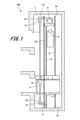
- FIG. 1 is a schematic diagram showing an elevator according to an embodiment of the present invention
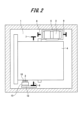
- FIG. 1 is a plan view showing an elevator according to an embodiment.
- FIG. 2 is a perspective view showing an example of an installation example of a detector in an elevator according to an embodiment.
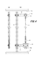
- 4(a) and 4(b) are perspective views showing another example of installation of a detector in an elevator according to the embodiment.
- 1 is an oblique view showing the configuration around a lower clip in an elevator detector in an example embodiment.
- FIG. 1 is an oblique view showing the configuration around a lower clip in an elevator detector in an example embodiment.
- FIG. 1 is a perspective view showing an elevator car and a sway suppression member according to a first embodiment.
- FIG. 2 is a plan view showing an elevator sway suppression member according to the first embodiment.
- FIG. 2 is a front view showing the elevator sway suppression member according to the first embodiment.
- FIG. 11 is a front view showing an elevator sway suppression member according to a second embodiment.
- FIG. 1 is a schematic diagram showing an elevator
- FIG. 2 is a plan view showing the elevator.
- the elevator 100 includes a hoist 3, a car 4 for carrying people and luggage, and a counterweight 5.
- the elevator 100 also includes car-side guide rails 6 and 7, and counterweight-side guide rails 8 and 9.
- the elevator 100 is equipped with a tape-shaped detection body 2 and a position detector 10 provided on the car 4 in order to detect the position of the car 4.
- the detection body 2 passes through an opening provided in the position detector 10.
- the position detector 10 detects the position of the car 4 by detecting the detection body 2.
- a magnetic tape is used as the detection body 2.
- a magnetic sensor that reads data from the detection body 2, which is a magnetic tape, is used as the position detector 10.
- an absolute position detector is used as the position detector 10.
- the car 4 is formed in a hollow, roughly rectangular parallelepiped shape.
- the car 4 moves up and down in the elevator shaft 1 along the car side guide rails 6, 7.
- the car side guide rails 6, 7 are arranged on both sides of the car 4.
- the car side guide rails 6, 7 are also erected in the elevator shaft 1.
- the car 4 is also provided with a pulley (not shown).
- a main rope (not shown) is wound around this pulley.
- the main rope is wound around a sheave of the hoisting machine 3 and a pulley provided on the counterweight.
- the hoisting machine 3 is installed at the top of the elevator shaft 1 in the ascending/descending direction.
- the location at which the hoisting machine 3 is installed is not limited to the top of the elevator shaft 1, and it may be installed at the bottom of the elevator shaft 1.
- a machine room may be provided in the elevator shaft 1, and the hoisting machine 3 may be installed in this machine room.
- a counterweight 5 is disposed below the hoist 3.
- the counterweight 5 moves up and down the hoistway 1 along counterweight-side guide rails 8, 9.
- the counterweight-side guide rails 8, 9 are disposed on both sides of the counterweight 5.
- the counterweight-side guide rails 8, 9 are erected within the hoistway 1.
- the detector 2 extends from the top 1a to the bottom (pit) 1b of the elevator shaft 1 along the ascending and descending direction of the car 4.
- An upper bracket 12 is fixed to the upper part of the car-side guide rail 6, and a lower bracket 11 is fixed to the lower part of the car-side guide rail 6.
- An upper tape fixing part 13 is fixed to the upper bracket 12, and a lower tape fixing part 15 is fixed to the lower bracket 11.
- An upper clip 14 is provided at the upper end of the detection body 2.
- the upper clip 14 is fixed to the upper tape fixing part 13.
- a lower clip 16 is provided at the lower end of the detection body 2.
- the lower clip 16 is fixed to the lower tape fixing part 15. Note that although an example in which the upper tape fixing part 13 and the lower tape fixing part 15 are provided has been described, this is not limiting.
- the upper clip 14 may be fixed to the upper bracket 12, and the lower clip 16 may be fixed to the lower bracket 11.
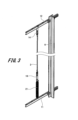
- Fig. 3 is a perspective view showing an example of installation of the detection body 2. In the example shown in Fig. 3, an installation example without providing the upper tape fixing part 13 and the lower tape fixing part 15 will be described.
- the upper clip 14 provided at the upper end of the detection body 2 is fixed to the upper bracket 12.
- the lower clip 16 provided at the lower end of the detection body 2 is provided with a spring 21.
- the upper end of the spring 21 is fixed to the lower clip 16, and the lower end of the spring 21 is fixed to the lower bracket 11.
- the detection body 2 is applied with tension by the spring force of the spring 21.
- FIG. 4(a) and 4(b) are diagrams showing other examples of installation of the detection body 2.
- an upper clip 14 provided at the upper end of the detection body 2 is fixed to an upper bracket 12 or an upper tape fixing part 13.
- a lower clip 16 provided at the lower end of the detection body 2 is inserted into a lower bracket 11 or a lower tape fixing part 15.
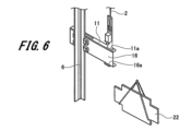
- Figures 5 and 6 are perspective views showing the configuration around the lower clip 16. Note that the example shown in Figures 5 and 6 shows an example in which the lower tape fixing portion 15 is not provided. As shown in Figures 5 and 6, an insertion hole 11a is formed in the lower bracket 11. The lower clip 16 is inserted into the insertion hole 11a. The lower end of the lower clip 16 protrudes from the lower end of the lower bracket 11. A hook 16a is formed at the lower end of the lower clip 16. When the hook 16a abuts against the lower bracket 11, it is possible to regulate the displacement of the detection body 2 in the contraction direction.
- a weight 22 is removably attached to the hook 16a.
- the load of the weight 22 is applied to the detection body 2 via the lower clip 16, and tension can be applied to the detection body 2.
- the position at which the lower bracket 11 is fixed to the car-side guide rail 6 is set based on the state in which the detection body 2 is stretched with the weight 22 hung on the lower clip 16.
- the detection body 2 may be subject to large swings due to earthquakes or wind within the hoistway 1. For this reason, the elevator 100 of this embodiment is provided with a member for suppressing the swinging of the detection body 2.
- Fig. 7 is a perspective view showing the car 4 and the vibration suppressing member according to the first embodiment.
- Fig. 8 is a plan view showing the vibration suppressing member according to the first embodiment.
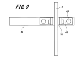
- Fig. 9 is a front view showing the vibration suppressing member according to the first embodiment.
- a vibration suppression member 31 and an anti-vibration bracket 42 are installed in the elevator shaft 1.
- the anti-vibration bracket 42 is fixed to the car-side guide rail 6.
- the anti-vibration bracket 42 protrudes from the car-side guide rail 6 in a direction perpendicular to the direction in which the detection body 2 extends.
- a plurality of anti-vibration brackets 42 are installed at predetermined heights in the elevator shaft 1.
- the vibration suppression member 31 is fixed to the vibration prevention bracket 42 via a fixing part 43.
- the fixing part 43 is fixed to the vibration prevention bracket 42 via a fixing screw 45. Note that the method of fixing the fixing part 43 is not limited to the fixing screw 45, and various other fixing methods can be applied.
- the vibration suppression member 31 is disposed opposite the detection body 2.
- the vibration suppression member 31 is, for example, composed of a magnet. Therefore, the vibration suppression member 31 attracts the detection body 2, which is composed of magnetic tape, by magnetic force. This makes it possible to prevent the detection body 2 from shaking significantly due to earthquakes or wind, and to prevent the detection body 2 from getting caught on other members installed in the elevator shaft 1.
- the position detector 10 peels the detection object 2 off the vibration suppression member 31. After the car 4 passes through the vibration suppression member 31, the detection object 2 is again attracted to the vibration suppression member 31.
- the vibration suppression member 31 can be round, square, or of any other suitable shape. In order to facilitate adhesion of the detection body 2, it is preferable that the vibration suppression member 31 has a shape that has a flat surface that adheres to the detection body 2.
- the length of the width of the vibration suppression member 31, which is perpendicular to the direction in which the detection body 2 extends, is set to be longer than the length of the detection body 2 in the width direction. This allows the detection body 2 to be reliably adhered to the vibration suppression member 31.
- the anti-sway bracket 42 is arranged to protrude from the car-side guide rail 6 in a direction perpendicular to the direction in which the detection body 2 extends. Therefore, even if the detection body 2 sways significantly and comes off the vibration suppression member 31, the anti-sway bracket 42 can prevent the detection body 2 from coming into contact with other members.
- a magnet is used as the vibration suppression member 31, but this is not limited to this, and any magnetic material that can be attracted by the magnetic force of other metals, etc. can be used.
- FIG. 10 is a front view showing a vibration suppressing member according to the second embodiment.
- the vibration suppression member 32 in the second embodiment is formed from a longer member than the vibration suppression member 31 in the first embodiment.
- the vibration suppression member 32 is arranged across multiple (e.g., two) vibration-stop brackets 42, 42 that are spaced apart along the lifting and lowering direction. In this way, by forming the vibration suppression member 32 from a long member, the vibration of the detection body 2 can be more firmly prevented.
- the vibration suppression member 32 according to the second embodiment may be placed in the middle of the elevator shaft 1 where the detector 2 vibrates the most, and the vibration suppression member 31 according to the first embodiment may be placed in other locations.
- the configuration of elevator 100 is not limited to the 2:1 roping elevator shown in Figure 1, but can be a 1:1 roping elevator, a hydraulic elevator, or any other type of elevator.
Landscapes
- Indicating And Signalling Devices For Elevators (AREA)
- Cage And Drive Apparatuses For Elevators (AREA)
Priority Applications (2)
| Application Number | Priority Date | Filing Date | Title |
|---|---|---|---|
| JP2025527391A JPWO2024262016A1 (https=) | 2023-06-23 | 2023-06-23 | |
| PCT/JP2023/023351 WO2024262016A1 (ja) | 2023-06-23 | 2023-06-23 | エレベーター |
Applications Claiming Priority (1)
| Application Number | Priority Date | Filing Date | Title |
|---|---|---|---|
| PCT/JP2023/023351 WO2024262016A1 (ja) | 2023-06-23 | 2023-06-23 | エレベーター |
Publications (1)
| Publication Number | Publication Date |
|---|---|
| WO2024262016A1 true WO2024262016A1 (ja) | 2024-12-26 |
Family
ID=93935253
Family Applications (1)
| Application Number | Title | Priority Date | Filing Date |
|---|---|---|---|
| PCT/JP2023/023351 Ceased WO2024262016A1 (ja) | 2023-06-23 | 2023-06-23 | エレベーター |
Country Status (2)
| Country | Link |
|---|---|
| JP (1) | JPWO2024262016A1 (https=) |
| WO (1) | WO2024262016A1 (https=) |
Citations (5)
| Publication number | Priority date | Publication date | Assignee | Title |
|---|---|---|---|---|
| JP2015113180A (ja) * | 2013-12-09 | 2015-06-22 | フジテック株式会社 | エレベータのかご位置検出装置の調整方法 |
| JP2019077546A (ja) * | 2017-10-26 | 2019-05-23 | フジテック株式会社 | エレベータ |
| JP2019081647A (ja) * | 2017-10-31 | 2019-05-30 | フジテック株式会社 | ダブルデッキエレベータ |
| US20190367323A1 (en) * | 2016-09-30 | 2019-12-05 | Inventio Ag | Vibration stabilizer for an information carrier |
| US20210078826A1 (en) * | 2019-09-12 | 2021-03-18 | Thyssenkrupp Elevator Corporation | Magnetic tape stabilizing systems |
-
2023
- 2023-06-23 WO PCT/JP2023/023351 patent/WO2024262016A1/ja not_active Ceased
- 2023-06-23 JP JP2025527391A patent/JPWO2024262016A1/ja active Pending
Patent Citations (5)
| Publication number | Priority date | Publication date | Assignee | Title |
|---|---|---|---|---|
| JP2015113180A (ja) * | 2013-12-09 | 2015-06-22 | フジテック株式会社 | エレベータのかご位置検出装置の調整方法 |
| US20190367323A1 (en) * | 2016-09-30 | 2019-12-05 | Inventio Ag | Vibration stabilizer for an information carrier |
| JP2019077546A (ja) * | 2017-10-26 | 2019-05-23 | フジテック株式会社 | エレベータ |
| JP2019081647A (ja) * | 2017-10-31 | 2019-05-30 | フジテック株式会社 | ダブルデッキエレベータ |
| US20210078826A1 (en) * | 2019-09-12 | 2021-03-18 | Thyssenkrupp Elevator Corporation | Magnetic tape stabilizing systems |
Also Published As
| Publication number | Publication date |
|---|---|
| JPWO2024262016A1 (https=) | 2024-12-26 |
Similar Documents
| Publication | Publication Date | Title |
|---|---|---|
| US5861084A (en) | System and method for minimizing horizontal vibration of elevator compensating ropes | |
| CN100515904C (zh) | 电梯装置 | |
| KR20150095918A (ko) | 리프트의 설치 방법 | |
| JP2000034072A (ja) | エレベータ巻上機の据付装置 | |
| US6119816A (en) | Emergency stop releasing method for elevator | |
| KR101270849B1 (ko) | 승강실을 구동하기 위한 지지 수단을 가진 장치 및 대응 지지 수단 | |
| JP2003146555A (ja) | エレベータ | |
| WO2024262016A1 (ja) | エレベーター | |
| JP6751373B2 (ja) | 非常停止装置及びエレベーター | |
| JP4992281B2 (ja) | エレベータ装置 | |
| WO2024262015A1 (ja) | エレベーター | |
| WO2024262014A1 (ja) | エレベーター | |
| JP6684473B2 (ja) | 複数の釣合い錘を備えるエレベータ | |
| JP2003276970A (ja) | エレベーター装置 | |
| JPH1087228A (ja) | エレベータ | |
| JP4658067B2 (ja) | エレベータ装置 | |
| JPH082844A (ja) | エレベーター釣合鎖用安全装置 | |
| JP2001048443A (ja) | エレベータ | |
| JP4056475B2 (ja) | エレベーター装置 | |
| JP4770241B2 (ja) | エレベーター装置 | |
| CN119284688A (zh) | 电梯曳引钢丝绳防晃装置 | |
| JP2007008611A (ja) | エレベータ装置及びエレベータの検査方法 | |
| KR101830837B1 (ko) | 엘리베이터 조속기 로프 텐션 장치 | |
| JP3438697B2 (ja) | 機械室レスエレベータ装置 | |
| JP2025109340A (ja) | エレベーター及び保護カバー |
Legal Events
| Date | Code | Title | Description |
|---|---|---|---|
| 121 | Ep: the epo has been informed by wipo that ep was designated in this application |
Ref document number: 23942447 Country of ref document: EP Kind code of ref document: A1 |
|
| ENP | Entry into the national phase |
Ref document number: 2025527391 Country of ref document: JP Kind code of ref document: A |
|
| WWE | Wipo information: entry into national phase |
Ref document number: 2025527391 Country of ref document: JP |
|
| NENP | Non-entry into the national phase |
Ref country code: DE |