WO2024262015A1 - エレベーター - Google Patents
エレベーター Download PDFInfo
- Publication number
- WO2024262015A1 WO2024262015A1 PCT/JP2023/023350 JP2023023350W WO2024262015A1 WO 2024262015 A1 WO2024262015 A1 WO 2024262015A1 JP 2023023350 W JP2023023350 W JP 2023023350W WO 2024262015 A1 WO2024262015 A1 WO 2024262015A1
- Authority
- WO
- WIPO (PCT)
- Prior art keywords
- detection body
- elevator
- suppression member
- car
- vibration suppression
- Prior art date
- Legal status (The legal status is an assumption and is not a legal conclusion. Google has not performed a legal analysis and makes no representation as to the accuracy of the status listed.)
- Ceased
Links
Images




Classifications
-
- B—PERFORMING OPERATIONS; TRANSPORTING
- B66—HOISTING; LIFTING; HAULING
- B66B—ELEVATORS; ESCALATORS OR MOVING WALKWAYS
- B66B3/00—Applications of devices for indicating or signalling operating conditions of elevators
- B66B3/02—Position or depth indicators
Definitions
- the present invention relates to elevators.
- a shielding plate is installed in the elevator shaft to detect the position of the car, and when the car passes over the shielding plate, a detector installed in the car detects the shielding plate to detect the car's position.
- a technology has been proposed in which a tape-shaped detector is installed in the elevator shaft along the direction in which the car rises and falls, and this detector is detected by a position detector installed in the car to detect the car's position.
- Patent Document 1 describes a technology that provides a just level sensor that detects when the car has landed at each floor landing. Patent Document 1 also describes a technology in which the car is manually operated to the top floor or bottom floor, and then the car is moved back and forth within the elevator shaft, and the position on the magnetic tape when the just level sensor is activated is recorded as just level.
- the detection body is in the shape of a tape, and is a long object that extends from the top of the elevator to the bottom. As a result, there is a risk that the detection body will swing violently due to earthquakes or strong winds, and that the detection body may become caught on other components installed in the elevator.
- the objective of this study is to take the above problems into consideration and provide an elevator that can suppress the shaking of the detected object.
- the elevator is equipped with a car that moves up and down the elevator shaft, a tape-shaped detection body, a position detector, and a sway suppression member.
- the detection body extends from the top of the elevator shaft to the bottom.
- the position detector is provided on the car and detects the position of the car by detecting the detection body.
- the sway suppression member is provided in the elevator shaft, surrounds the periphery of the detection body, and has an opening through which the position detector can pass.
- the elevator with the above configuration can suppress the shaking of the detection object and prevent the detection object from getting caught on other components installed in the elevator shaft.
- FIG. 1 is a schematic diagram showing an elevator according to an embodiment of the present invention
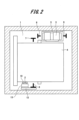
- FIG. 1 is a plan view showing an elevator according to an embodiment.
- FIG. 2 is a perspective view showing an example of an installation example of a detector in an elevator according to an embodiment.
- 4(a) and 4(b) are perspective views showing another example of installation of a detector in an elevator according to the embodiment.
- 1 is an oblique view showing the configuration around a lower clip in an elevator detector in an example embodiment.
- FIG. 1 is an oblique view showing the configuration around a lower clip in an elevator detector in an example embodiment.
- FIG. 1 is a perspective view showing an elevator car and a sway suppression member according to a first embodiment.
- FIG. 2 is a plan view showing an elevator sway suppression member according to the first embodiment.
- FIG. 2 is a front view showing the elevator sway suppression member according to the first embodiment.
- 13 is a perspective view showing an elevator car and a sway suppression member according to a second embodiment.
- FIG. 11 is a plan view showing an elevator sway suppression member according to a second embodiment.
- FIG. 11 is a front view showing an elevator sway suppression member according to a second embodiment.
- FIG. 1 is a schematic diagram showing an elevator
- FIG. 2 is a plan view showing the elevator.
- the elevator 100 includes a hoist 3, a car 4 for carrying people and luggage, and a counterweight 5.
- the elevator 100 also includes car-side guide rails 6 and 7, and counterweight-side guide rails 8 and 9.
- the elevator 100 is equipped with a tape-shaped detection body 2 and a position detector 10 provided on the car 4 in order to detect the position of the car 4.
- the detection body 2 passes through an opening provided in the position detector 10.
- the position detector 10 detects the position of the car 4 by detecting the detection body 2.
- a magnetic tape is used as the detection body 2.
- a magnetic sensor that reads data from the detection body 2, which is a magnetic tape, is used as the position detector 10.
- an absolute position detector is used as the position detector 10.
- the detection body 2 is not limited to magnetic tape, but may be, for example, optical tape or any other type of tape-like detection body.
- the position detector 10 may be an optical sensor or any other type of position detector.
- the car 4 is formed in a hollow, roughly rectangular parallelepiped shape.
- the car 4 moves up and down in the elevator shaft 1 along the car side guide rails 6, 7.
- the car side guide rails 6, 7 are arranged on both sides of the car 4.
- the car side guide rails 6, 7 are also erected in the elevator shaft 1.
- the car 4 is also provided with a pulley (not shown).
- a main rope (not shown) is wound around this pulley.
- the main rope is wound around a sheave of the hoisting machine 3 and a pulley provided on the counterweight.
- the hoisting machine 3 is installed at the top of the elevator shaft 1 in the ascending/descending direction.
- the location at which the hoisting machine 3 is installed is not limited to the top of the elevator shaft 1, and it may be installed at the bottom of the elevator shaft 1.
- a machine room may be provided in the elevator shaft 1, and the hoisting machine 3 may be installed in this machine room.
- a counterweight 5 is disposed below the hoist 3.
- the counterweight 5 moves up and down the hoistway 1 along counterweight-side guide rails 8, 9.
- the counterweight-side guide rails 8, 9 are disposed on both sides of the counterweight 5.
- the counterweight-side guide rails 8, 9 are erected within the hoistway 1.
- the detector 2 extends from the top 1a to the bottom (pit) 1b of the elevator shaft 1 along the ascending and descending direction of the car 4.
- An upper bracket 12 is fixed to the upper part of the car-side guide rail 6, and a lower bracket 11 is fixed to the lower part of the car-side guide rail 6.
- An upper tape fixing part 13 is fixed to the upper bracket 12, and a lower tape fixing part 15 is fixed to the lower bracket 11.
- An upper clip 14 is provided at the upper end of the detection body 2.
- the upper clip 14 is fixed to the upper tape fixing part 13.
- a lower clip 16 is provided at the lower end of the detection body 2.
- the lower clip 16 is fixed to the lower tape fixing part 15. Note that although an example in which the upper tape fixing part 13 and the lower tape fixing part 15 are provided has been described, this is not limiting.
- the upper clip 14 may be fixed to the upper bracket 12, and the lower clip 16 may be fixed to the lower bracket 11.
- Fig. 3 is a perspective view showing an example of installation of the detection body 2. In the example shown in Fig. 3, an installation example without providing the upper tape fixing part 13 and the lower tape fixing part 15 will be described.
- the upper clip 14 provided at the upper end of the detection body 2 is fixed to the upper bracket 12.
- the lower clip 16 provided at the lower end of the detection body 2 is provided with a spring 21.
- the upper end of the spring 21 is fixed to the lower clip 16, and the lower end of the spring 21 is fixed to the lower bracket 11.
- the detection body 2 is applied with tension by the spring force of the spring 21.
- FIG. 4(a) and 4(b) are diagrams showing other examples of installation of the detection body 2.
- an upper clip 14 provided at the upper end of the detection body 2 is fixed to an upper bracket 12 or an upper tape fixing part 13.
- a lower clip 16 provided at the lower end of the detection body 2 is inserted into a lower bracket 11 or a lower tape fixing part 15.
- Figures 5 and 6 are perspective views showing the configuration around the lower clip 16. Note that the example shown in Figures 5 and 6 shows an example in which the lower tape fixing portion 15 is not provided. As shown in Figures 5 and 6, an insertion hole 11a is formed in the lower bracket 11. The lower clip 16 is inserted into the insertion hole 11a. The lower end of the lower clip 16 protrudes from the lower end of the lower bracket 11. A hook 16a is formed at the lower end of the lower clip 16. When the hook 16a abuts against the lower bracket 11, it is possible to regulate the displacement of the detection body 2 in the contraction direction.
- a weight 22 is removably attached to the hook 16a.
- the load of the weight 22 is applied to the detection body 2 via the lower clip 16, and tension can be applied to the detection body 2.
- the position at which the lower bracket 11 is fixed to the car-side guide rail 6 is set based on the state in which the detection body 2 is stretched with the weight 22 hung on the lower clip 16.
- the detection body 2 may be subject to large swings due to earthquakes or wind within the hoistway 1. For this reason, the elevator 100 of this embodiment is provided with a member for suppressing the swinging of the detection body 2.
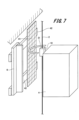
- Fig. 7 is a perspective view showing the car 4 and the vibration suppressing member according to the first embodiment.
- Fig. 8 is a plan view showing the vibration suppressing member according to the first embodiment.
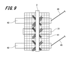
- Fig. 9 is a front view showing the vibration suppressing member according to the first embodiment.
- a vibration suppression member 31, a protective wire mesh 41, and multiple anti-vibration brackets 42 are installed in the elevator shaft 1.
- the multiple anti-vibration brackets 42 are fixed to the car-side guide rail 6.
- the anti-vibration brackets 42 protrude from the car-side guide rail 6 in a direction perpendicular to the direction in which the detection body 2 extends.
- the multiple anti-vibration brackets 42 are installed at predetermined heights in the elevator shaft 1.
- a protective wire mesh 41 is fixed to the anti-sway bracket 42.
- the protective wire mesh 41 is supported by the anti-sway bracket 42 and is positioned opposite the detection body 2 with a gap between them.
- the protective wire mesh 41 like the detection body 2, extends from the top 1a of the elevator shaft 1 to the pit 1b.
- vibration suppression members 31 are provided on the protective wire mesh 41 at predetermined heights along the elevator shaft 1.
- the vibration suppression members 31 are attached to the mesh of the protective wire mesh 41 with wire material such as wire or resin.
- the vibration suppression member 31 is formed of a substantially semicircular member having an arc.
- the vibration suppression member 31 is disposed so as to surround the periphery of the detection body 2.
- the vibration suppression member 31 also has an opening through which the position detector 10 can pass.
- the vibration suppression member 31 is formed in a substantially semicircular shape, this is not limiting.
- the vibration suppression member 31 may be formed in various shapes, such as a square or hexagon, having an opening through which the position detector 10 can pass.
- forming the vibration suppression member 31 in an arc shape can prevent the detection body 2 from getting caught on the corners of the vibration suppression member 31.
- forming it in an arc shape can allow the detection body 2 to slide along the wall surface of the vibration suppression member 31 and return the detection body 2 to the desired position.
- the vibration suppression member 31 is preferably made of a soft material such as rubber or resin. This prevents the detection body 2 from being damaged when the detection body 2 comes into contact with the vibration suppression member 31, and also allows the vibration of the detection body 2 to be dampened by the vibration suppression member 31.
- the vibration suppression member 31 can be easily installed at any position. Furthermore, the protective wire mesh 41 faces the detection body 2 and is continuously arranged from the top 1a of the elevator shaft 1 to the pit 1b. This makes it possible to suppress the vibration of the detection body 2 not only by the vibration suppression member 31 but also by the protective wire mesh 41. Also, while an example of attaching the vibration suppression member 31 to the protective wire mesh 41 has been described, this is not limiting, and the protective wire mesh 41 itself may be used as a vibration suppression member by bending the protective wire mesh 41 to surround the detection body 2.
- the anti-sway bracket 42 is arranged to protrude from the car-side guide rail 6 in a direction perpendicular to the direction in which the detection body 2 extends. Therefore, even if the detection body 2 sways significantly and comes off the vibration suppression member 31, the anti-sway bracket 42 can prevent the detection body 2 from coming into contact with other members.
- a protective wire 45 may be fixed to the anti-sway bracket 42.
- the protective wire 45 extends in a direction perpendicular to the direction in which the detection body 2 extends. This protective wire 45 can also prevent the detection body 2 from coming into contact with other components.
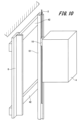
- Fig. 10 is a perspective view showing the car 4 and the vibration suppressing member according to the second embodiment.
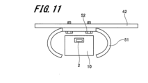
- Fig. 11 is a plan view showing the vibration suppressing member according to the second embodiment.
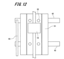
- Fig. 12 is a front view showing the vibration suppressing member according to the second embodiment.
- the vibration suppression member 51 is formed in a pipe shape with an opening on one side.
- the vibration suppression member 51 is formed in a roughly cylindrical shape with an arc.
- the vibration suppression member 51 extends from the top 1a of the elevator shaft 1 to the pit 1b along the detection body 2.
- the vibration suppression member 51 is fixed to the vibration prevention bracket 42, for example, via a fixing screw 52. Note that the method of fixing the vibration suppression member 51 is not limited to the fixing screw 52, and various other fixing methods can be applied.
- the sway suppression member 51 also has an opening that runs from the top 1a of the elevator shaft 1 to the pit 1b along the detection body 2.
- the opening of the sway suppression member 51 is large enough to allow the position detector 10 to pass through. This prevents the position detector 10 from coming into contact with the sway suppression member 51.
- the detection body 2 is inserted into the cylindrical hole of the vibration suppression member 51. Therefore, the detection body 2 is surrounded by the vibration suppression member 51. This makes it possible to prevent the detection body 2 from shaking significantly due to earthquakes or wind, and to prevent the detection body 2 from getting caught on other components installed in the elevator shaft 1.
- the vibration suppression member 51 is formed in a generally cylindrical shape having an arc
- the vibration suppression member 51 may be formed in a rectangular or hexagonal tube shape having an opening through which the position detector 10 can pass.
- forming the vibration suppression member 51 in a generally cylindrical shape can prevent the detection body 2 from getting caught on the corners of the vibration suppression member 51. By forming it in an arc shape, the detection body 2 can be slid along the wall surface of the vibration suppression member 51 to return the detection body 2 to the desired position.
- a wiring cable 55 connected to the hall button on each floor, etc. may also be fixed thereto.
- the protective wire mesh 41 may also be installed and the vibration suppression member 51 may be attached to the protective wire mesh 41.
- the configuration of elevator 100 is not limited to the 2:1 roping elevator shown in Figure 1, but can be a 1:1 roping elevator, a hydraulic elevator, or any other type of elevator.
Landscapes
- Indicating And Signalling Devices For Elevators (AREA)
Abstract
エレベーターは、昇降路を昇降移動する乗りかごと、テープ状の検出体と、位置検出器と、揺れ抑制部材と、を備えている。検出体は、昇降路の頂部から最下部にかけて延在する。位置検出器は、乗りかごに設けられ、検出体を検出することで、乗りかごの位置を検出する。揺れ抑制部材は、昇降路に設けられ、検出体の周囲を囲み、位置検出器が通過可能な開口を有する。
Description
本発明は、エレベーターに関するものである。
従来のエレベーターでは、乗りかごの位置を検出するために、昇降路内に遮蔽板を設置し、乗りかごが遮蔽板を通過する際に、乗りかごに設けた検出器により遮蔽板を検出することで乗りかごの位置を検出していた。また、近年では、テープ状の検出体を昇降路内に乗りかごの昇降方向に沿って設置し、この検出体を乗りかごに設けた位置検出器で検出することで、乗りかごの位置を検出する技術が提案されている。
このような技術としては、例えば、特許文献1に記載されているようなものがある。特許文献1には、かごが各階乗場に着床したことを検出するジャストレベルセンサを設ける技術が記載されている。また、特許文献1には、かごを手動運転にて最上階及び最下階に運転した後、かごを昇降路内を往復させて、ジャストレベルセンサが作動したときの磁気テープ上の位置をジャストレベルとして記録する技術が記載されている。
しかしながら、検出体は、テープ状に形成されており、昇降路の頂部から最下部までの延在する長尺物である。そのため、地震や風により検出体が大きく揺れるおそれがあり、昇降路内に設置した他の部材に検出体が引っ掛かるおそれがあった。
本目的は、上記の問題点を考慮し、検出体の揺れを抑制できるエレベーターを提供することにある。
上記課題を解決し、目的を達成するため、エレベーターは、昇降路を昇降移動する乗りかごと、テープ状の検出体と、位置検出器と、揺れ抑制部材と、を備えている。検出体は、昇降路の頂部から最下部にかけて延在する。位置検出器は、乗りかごに設けられ、検出体を検出することで、乗りかごの位置を検出する。揺れ抑制部材は、昇降路に設けられ、検出体の周囲を囲み、位置検出器が通過可能な開口を有する。
上記構成のエレベーターによれば、検出体の揺れを抑制でき、検出体が昇降路内に設置した他の部材に引っ掛かることを防止することができる。
以下、エレベーターの実施の形態例について、図1~図12を参照して説明する。なお、各図において共通の部材には、同一の符号を付している。
1.実施の形態例
1-1.エレベーターの構成
まず、実施の形態例(以下、「本例」という。)にかかるエレベーターの構成について図1及び図2を参照して説明する。
図1は、エレベーターを示す概略構成図、図2は、エレベーターを示す平面図である。
1-1.エレベーターの構成
まず、実施の形態例(以下、「本例」という。)にかかるエレベーターの構成について図1及び図2を参照して説明する。
図1は、エレベーターを示す概略構成図、図2は、エレベーターを示す平面図である。
図1及び図2に示すように、エレベーター100は、巻上機3と、人や荷物を載せる乗りかご4と、釣合錘5と、を備える。また、エレベーター100は、かご側ガイドレール6、7と、おもり側ガイドレール8、9とを備えている。
さらに、エレベーター100は、乗りかご4の位置を検出するために、テープ状の検出体2と、乗りかご4に設けた位置検出器10と、を備えている。検出体2は、位置検出器10に設けた開口部を挿通している。そして、位置検出器10は、検出体2を検出することで、乗りかご4の位置を検出する。
検出体2としては、例えば、磁気テープが適用される。そして、位置検出器10としては、磁気テープである検出体2のデータを読み取る磁気センサが適用される。なお、位置検出器10としては、例えば、絶対位置検出器が適用される。
検出体2としては、磁気テープに限定されるものではなく、例えば、光学式テープやその他各種のテープ状の検出体が適用してもよい。そして、位置検出器10としても、光学式センサやその他各種の位置検出器が適用される。
乗りかご4は、中空の略直方体状に形成されている。乗りかご4は、かご側ガイドレール6、7に沿って昇降路1を昇降移動する。かご側ガイドレール6、7は、乗りかご4の両側に配置されている。また、かご側ガイドレール6、7は、昇降路1内に立設されている。また、乗りかご4には、不図示のプーリが設けられている。このプーリには、不図示の主ロープが巻き掛けられる。主ロープは、巻上機3の綱車と、釣合錘に設けたプーリに巻き掛けられる。
巻上機3は、昇降路1の昇降方向の上部に設置される。なお、巻上機3を設置する位置は、昇降路1の上部に限定されるものではなく、昇降路1の下部に設置してもよい。また、昇降路1に機械室を設け、この機械室に巻上機3を設置してもよい。
巻上機3の下方には、釣合錘5が配置されている。釣合錘5は、おもり側ガイドレール8、9に沿って昇降路1を昇降移動する。おもり側ガイドレール8、9は、釣合錘5の両側に配置されている。そして、おもり側ガイドレール8、9は、昇降路1内に立設されている。
検出体2は、昇降路1内において乗りかご4の昇降方向に沿って、昇降路1の頂部1aから最下部(ピット)1bにかけて延在している。また、かご側ガイドレール6の上部には、上部ブラケット12が固定されており、かご側ガイドレール6の下部には、下部ブラケット11が固定されている。また、上部ブラケット12には、上部テープ固定部13が固定されており、下部ブラケット11には、下部テープ固定部15が固定されている。
検出体2の上端部には、上部クリップ14が設けられている。そして、上部クリップ14は、上部テープ固定部13に固定されている。さらに、検出体2の下端部には、下部クリップ16が設けられている。そして、下部クリップ16は、下部テープ固定部15に固定されている。なお、上部テープ固定部13及び下部テープ固定部15を設けた例を説明したが、これに限定されるものではない。例えば、上部クリップ14を上部ブラケット12に固定し、下部クリップ16を下部ブラケット11に固定してもよい。
1-2.検出体の設置例
なお、乗りかご4の位置を正確に検出するためには、テープ状の検出体2に張力を付与し、検出体2が撓むことなく、昇降路1内に設置する必要がある。次に、検出体2に張力を付与して設置する例について図3から図6を参照して説明する。
図3は、検出体2の設置例の一例を示す斜視図である。図3に示す例では、上部テープ固定部13及び下部テープ固定部15を設けずに設置する例について説明する。
なお、乗りかご4の位置を正確に検出するためには、テープ状の検出体2に張力を付与し、検出体2が撓むことなく、昇降路1内に設置する必要がある。次に、検出体2に張力を付与して設置する例について図3から図6を参照して説明する。
図3は、検出体2の設置例の一例を示す斜視図である。図3に示す例では、上部テープ固定部13及び下部テープ固定部15を設けずに設置する例について説明する。
図3に示すように、検出体2の上端部に設けた上部クリップ14は、上部ブラケット12に固定されている。検出体2の下端部に設けた下部クリップ16には、ばね21が設けられている。ばね21の上端部は、下部クリップ16に固定されており、ばね21の下端部は、下部ブラケット11に固定されている。そして、検出体2は、ばね21のばね力により張力が付与される。
図4(a)及び図4(b)は、検出体2の設置例の他の例を示す図である。
図4(a)及び図4(b)に示すように、検出体2の上端部に設けた上部クリップ14は、上部ブラケット12又は上部テープ固定部13に固定される。検出体2の下端部に設けた下部クリップ16は、下部ブラケット11又は下部テープ固定部15に挿入される。
図4(a)及び図4(b)に示すように、検出体2の上端部に設けた上部クリップ14は、上部ブラケット12又は上部テープ固定部13に固定される。検出体2の下端部に設けた下部クリップ16は、下部ブラケット11又は下部テープ固定部15に挿入される。
図5及び図6は、下部クリップ16周りの構成を示す斜視図である。なお、図5及び図6に示す例では、下部テープ固定部15を設けない例を示している。図5及び図6に示すように、下部ブラケット11には、挿入孔11aが形成されている。挿入孔11aには、下部クリップ16が挿入されている。そして、下部ブラケット11の下端部から下部クリップ16の下端部が突出する。また、下部クリップ16の下端部には、フック16aが形成されている。フック16aが下部ブラケット11に当接することで、検出体2の縮み方向への変位を規制することができる。
また、図5及び図6に示すように、フック16aには、おもり22が着脱可能に取り付けられる。これにより、検出体2には、下部クリップ16を介しておもり22の荷重が加わり、検出体2に張力を付与することができる。なお、下部ブラケット11をかご側ガイドレール6に固定する位置は、下部クリップ16におもり22を掛けて、検出体2が伸びた状態を基準に設定される。
2.揺れ抑制部材
なお、検出体2は、昇降路1内において地震や風により大きく揺れるおそれがある。そのため、本例のエレベーター100には、検出体2の揺れを抑制する部材が設けられている。
なお、検出体2は、昇降路1内において地震や風により大きく揺れるおそれがある。そのため、本例のエレベーター100には、検出体2の揺れを抑制する部材が設けられている。
2-1.第1の実施の形態例
次に、図7から図9を参照して第1の実施の形態例にかかる揺れ抑制部材の構成について説明する。
図7は、第1の実施の形態例にかかる乗りかご4及び揺れ抑制部材を示す斜視図である。図8は、第1の実施の形態例にかかる揺れ抑制部材を示す平面図、図9は、第1の実施の形態例にかかる揺れ抑制部材を示す正面図である。
次に、図7から図9を参照して第1の実施の形態例にかかる揺れ抑制部材の構成について説明する。
図7は、第1の実施の形態例にかかる乗りかご4及び揺れ抑制部材を示す斜視図である。図8は、第1の実施の形態例にかかる揺れ抑制部材を示す平面図、図9は、第1の実施の形態例にかかる揺れ抑制部材を示す正面図である。
図7に示すように、昇降路1内には、揺れ抑制部材31と、保護金網41と、複数の揺れ止めブラケット42が設置されている。複数の揺れ止めブラケット42は、かご側ガイドレール6に固定されている。そして、揺れ止めブラケット42は、かご側ガイドレール6から検出体2が延在する方向と直交する方向に突出している。また、複数の揺れ止めブラケット42は、昇降路1内に所定の高さごとに設置される。
図7から図9に示すように、揺れ止めブラケット42には、保護金網41が固定されている。保護金網41は、揺れ止めブラケット42に支持されて、検出体2と間隔を空けて対向して配置される。そして、保護金網41は、検出体2と同様に、昇降路1の頂部1aからピット1bまで延在している。
また、保護金網41には、揺れ抑制部材31が昇降路1に沿って所定の高さごとに複数設けられている。揺れ抑制部材31は、保護金網41の網目に針金や樹脂等の線材により取り付けられている。
揺れ抑制部材31は、円弧を有する略半円状の部材により形成されている。そして、揺れ抑制部材31は、検出体2の周囲を囲むようにして配置される。また、揺れ抑制部材31には、位置検出器10が通過可能な開口を有している。
このように、揺れ抑制部材31で検出体2の周囲を囲むことで、地震や風により検出体2が大きく揺れることを防止することができ、検出体2が昇降路1内に設置した他の部材に引っ掛かることを防止することができる。また、揺れ抑制部材31に位置検出器10が通過可能な開口を設けたことで、乗りかご4が揺れ抑制部材31を通過する際に、位置検出器10が揺れ抑制部材31に接触することを防ぐことができる。
なお、揺れ抑制部材31を略半円状に形成した例を説明したが、これに限定されるものではない。例えば、揺れ抑制部材31を、位置検出器10が通過可能な開口を有する四角形や六角形状等その他各種の形状に形成してもよい。しかしながら、揺れ抑制部材31を円弧状に形成することで、検出体2が揺れ抑制部材31の角部に引っ掛かることを防止することができる。さらに、円弧状に形成することで、揺れ抑制部材31の壁面に沿って検出体2を滑らせて、検出体2を所望の位置に戻すことができる。
また、揺れ抑制部材31の材質としては、ゴムや樹脂等の軟質な材質で形成することが好ましい。これにより、揺れ抑制部材31に検出体2が接触した際に、検出体2に傷がつくことを抑制できる、さらに、検出体2の揺れを揺れ抑制部材31で減衰させることができる。
また、揺れ抑制部材31を設置する部材として、保護金網41を適用することで、揺れ抑制部材31を任意の位置に容易に設置することができる。さらに、保護金網41が検出体2と対向して、昇降路1の頂部1aからピット1bまで連続して配置されている。これにより、揺れ抑制部材31だけでなく、保護金網41によっても検出体2の揺れを抑制することができる。また、保護金網41に揺れ抑制部材31を取り付ける例を説明したが、これに限定されるものではなく、保護金網41を、検出体2を囲むように曲げることで、保護金網41自体を揺れ抑制部材としてもよい。
また、揺れ止めブラケット42がかご側ガイドレール6から検出体2が延在する方向と直交する方向に突出して配置されている。そのため、検出体2が大きく揺れて揺れ抑制部材31から外れても、検出体2が他の部材に接触することを揺れ止めブラケット42で抑制することができる。
さらに、揺れ止めブラケット42には、保護番線45を固定してもよい。保護番線45は、検出体2が延在する方向と直交する方向に延在している。この保護番線45によっても検出体2が他の部材に接触することを抑制することができる。
2-2.第2の実施の形態例
次に、図10から図12を参照して第2の実施の形態例にかかる揺れ抑制部材の構成について説明する。なお、第1の実施の形態例にかかる揺れ抑制部材31と共通する部分には同一の符号を付して重複した説明を省略する。
図10は、第2の実施の形態例にかかる乗りかご4及び揺れ抑制部材を示す斜視図である。図11は、第2の実施の形態例にかかる揺れ抑制部材を示す平面図、図12は、第2の実施の形態例にかかる揺れ抑制部材を示す正面図である。
次に、図10から図12を参照して第2の実施の形態例にかかる揺れ抑制部材の構成について説明する。なお、第1の実施の形態例にかかる揺れ抑制部材31と共通する部分には同一の符号を付して重複した説明を省略する。
図10は、第2の実施の形態例にかかる乗りかご4及び揺れ抑制部材を示す斜視図である。図11は、第2の実施の形態例にかかる揺れ抑制部材を示す平面図、図12は、第2の実施の形態例にかかる揺れ抑制部材を示す正面図である。
図10から図12に示すように、揺れ抑制部材51は、一面に開口部を有するパイプ状に形成されている。そして、揺れ抑制部材51は、円弧を有する略円筒状に形成されている。揺れ抑制部材51は、検出体2に沿って昇降路1の頂部1aからピット1bまで延在している。また、図11及び図12に示すように、揺れ抑制部材51は、例えば、固定ネジ52を介して揺れ止めブラケット42に固定されている。なお、揺れ抑制部材51の固定方法としては、固定ネジ52に限定されるものではなく、その他各種の固定方法を適用できるものである。
また、揺れ抑制部材51には、検出体2に沿って昇降路1の頂部1aからピット1bまで連続する開口部が形成されている。揺れ抑制部材51の開口部は、位置検出器10が通過可能な大きさに形成されている。これにより、位置検出器10が揺れ抑制部材51に接触することを防ぐことができる。
さらに、揺れ抑制部材51の筒孔内には、検出体2が挿通している。そのため、検出体2の周囲は、揺れ抑制部材51によって囲まれる。これにより、地震や風により検出体2が大きく揺れることを防止することができ、検出体2が昇降路1内に設置した他の部材に引っ掛かることを防止することができる。
なお、揺れ抑制部材51を、円弧を有する略円筒状に形成した例を説明したが、これに限定されるものではない。例えば、揺れ抑制部材51を、位置検出器10が通過可能な開口を有する四角形や六角形等の角筒状に形成してもよい。しかしながら、揺れ抑制部材51を略円筒状に形成することで、検出体2が揺れ抑制部材51の角部に引っ掛かることを防止することができる。円弧状に形成することで、揺れ抑制部材51の壁面に沿って検出体2を滑らせて、検出体2を所望の位置に戻すことができる。
また、図12に示すように、揺れ止めブラケット42には、揺れ抑制部材51を固定するだけでなく、各階のホールボタンなどに接続される配線ケーブル55を固定してもよい。
なお、第2の実施の形態例においても保護金網41を設置し、揺れ抑制部材51を保護金網41に取り付けてもよい。
なお、本発明は、上述し、かつ図面に示した実施の形態に限定されるものではなく、請求の範囲に記載した発明の要旨を逸脱しない範囲内で種々の変形実施が可能である。
例えば、上述した実施の形態例は本発明を分かりやすく説明するために装置及びシステムの構成を詳細かつ具体的に説明したものであり、必ずしも説明した全ての構成を備えるものに限定されない。また、ここで説明した実施の形態の構成の一部を他の実施の形態の構成に置き換えることは可能であり、さらにはある実施の形態の構成に他の実施の形態の構成を加えることも可能である。また、実施の形態の構成の一部について、他の構成の追加、削除、置換することも可能である。
エレベーター100の構成としては、図1に示す2:1ローピングのエレベーターに限定されるものではなく、1:1ローピングのエレベーターや油圧式のエレベーター等その他各種のエレベーターが適用できるものである。
なお、本明細書において、「平行」及び「直交」等の単語を使用したが、これらは厳密な「平行」及び「直交」のみを意味するものではなく、「平行」及び「直交」を含み、さらにその機能を発揮し得る範囲にある、「略平行」や「略直交」の状態であってもよい。
1…昇降路、 1a…頂部、 1b…最下部、 2…検出体、 3…巻上機、 4…乗りかご、 5…釣合錘、 6、7…かご側ガイドレール、 8、9…側ガイドレール、 10…位置検出器、 11…下部ブラケット、 12…上部ブラケット、 14…上部クリップ、 16…下部クリップ、 16a…フック、 21…ばね、 22…おもり、 31、51…揺れ抑制部材、 41…保護金網、 42…揺れ止めブラケット、 45…保護番線、 52…固定ネジ、 55…配線ケーブル、 100…エレベーター
Claims (7)
- 昇降路を昇降移動する乗りかごと、
前記昇降路の頂部から最下部にかけて延在するテープ状の検出体と、
前記乗りかごに設けられ、前記検出体を検出することで、前記乗りかごの位置を検出する位置検出器と、
前記昇降路に設けられ、前記検出体の周囲を囲み、前記位置検出器が通過可能な開口を有する揺れ抑制部材と、
を備えたエレベーター。 - 前記揺れ抑制部材は、円弧状に形成されている
請求項1に記載のエレベーター。 - 前記昇降路に設けられ、前記検出体が延在する方向と直交する方向に延在する揺れ止めブラケットを備え、
前記揺れ抑制部材は、前記揺れ止めブラケットに設置される
請求項1に記載のエレベーター。 - 前記検出体と対向し、かつ前記揺れ止めブラケットに固定されて、前記検出体が延在する方向に延在して配置される保護金網を備えた
請求項3に記載のエレベーター。 - 前記揺れ抑制部材は、前記保護金網に設置される
請求項4に記載のエレベーター。 - 前記揺れ抑制部材は、前記検出体が延在する方向に沿って延在する筒状の部材である
請求項1に記載のエレベーター。 - 前記検出体は、磁気テープであり、
前記位置検出器は、前記検出体のデータを読み取る磁気センサである
請求項1に記載のエレベーター。
Priority Applications (2)
| Application Number | Priority Date | Filing Date | Title |
|---|---|---|---|
| JP2025527390A JPWO2024262015A1 (ja) | 2023-06-23 | 2023-06-23 | |
| PCT/JP2023/023350 WO2024262015A1 (ja) | 2023-06-23 | 2023-06-23 | エレベーター |
Applications Claiming Priority (1)
| Application Number | Priority Date | Filing Date | Title |
|---|---|---|---|
| PCT/JP2023/023350 WO2024262015A1 (ja) | 2023-06-23 | 2023-06-23 | エレベーター |
Publications (1)
| Publication Number | Publication Date |
|---|---|
| WO2024262015A1 true WO2024262015A1 (ja) | 2024-12-26 |
Family
ID=93935245
Family Applications (1)
| Application Number | Title | Priority Date | Filing Date |
|---|---|---|---|
| PCT/JP2023/023350 Ceased WO2024262015A1 (ja) | 2023-06-23 | 2023-06-23 | エレベーター |
Country Status (2)
| Country | Link |
|---|---|
| JP (1) | JPWO2024262015A1 (ja) |
| WO (1) | WO2024262015A1 (ja) |
Citations (3)
| Publication number | Priority date | Publication date | Assignee | Title |
|---|---|---|---|---|
| JP2013230936A (ja) * | 2012-04-26 | 2013-11-14 | Cedes Ag | エレベータ設備、測定装置、マーキング装置、及びガイド要素 |
| WO2020115901A1 (ja) * | 2018-12-07 | 2020-06-11 | 株式会社日立製作所 | エレベーター装置 |
| CN114380157A (zh) * | 2020-10-05 | 2022-04-22 | 奥的斯电梯公司 | 电梯位置参考系统 |
-
2023
- 2023-06-23 WO PCT/JP2023/023350 patent/WO2024262015A1/ja not_active Ceased
- 2023-06-23 JP JP2025527390A patent/JPWO2024262015A1/ja active Pending
Patent Citations (3)
| Publication number | Priority date | Publication date | Assignee | Title |
|---|---|---|---|---|
| JP2013230936A (ja) * | 2012-04-26 | 2013-11-14 | Cedes Ag | エレベータ設備、測定装置、マーキング装置、及びガイド要素 |
| WO2020115901A1 (ja) * | 2018-12-07 | 2020-06-11 | 株式会社日立製作所 | エレベーター装置 |
| CN114380157A (zh) * | 2020-10-05 | 2022-04-22 | 奥的斯电梯公司 | 电梯位置参考系统 |
Also Published As
| Publication number | Publication date |
|---|---|
| JPWO2024262015A1 (ja) | 2024-12-26 |
Similar Documents
| Publication | Publication Date | Title |
|---|---|---|
| JP2003146555A (ja) | エレベータ | |
| KR101270849B1 (ko) | 승강실을 구동하기 위한 지지 수단을 가진 장치 및 대응 지지 수단 | |
| JP6751373B2 (ja) | 非常停止装置及びエレベーター | |
| JP7004220B2 (ja) | エレベータ用ガイドレール保持装置 | |
| JP7281482B2 (ja) | エレベーター装置 | |
| JP2003118949A (ja) | エレベータ装置 | |
| JP4992281B2 (ja) | エレベータ装置 | |
| JP4270018B2 (ja) | エレベーター装置 | |
| WO2024262016A1 (ja) | エレベーター | |
| WO2024262014A1 (ja) | エレベーター | |
| CN101412480A (zh) | 电梯装置 | |
| JP7111670B2 (ja) | エレベータ装置 | |
| JP4658067B2 (ja) | エレベータ装置 | |
| JPH05178564A (ja) | エレベータ制御用ケーブルの制振装置 | |
| JP4056475B2 (ja) | エレベーター装置 | |
| JPH1087228A (ja) | エレベータ | |
| JP4770241B2 (ja) | エレベーター装置 | |
| JPH082844A (ja) | エレベーター釣合鎖用安全装置 | |
| JP2025109340A (ja) | エレベーター及び保護カバー | |
| JP2018043819A (ja) | 複数の釣合い錘を備えるエレベータ | |
| JP3528840B2 (ja) | 機械室レスエレベータ装置 | |
| JP6293078B2 (ja) | エレベータ装置 | |
| JP2007008611A (ja) | エレベータ装置及びエレベータの検査方法 | |
| JP3438697B2 (ja) | 機械室レスエレベータ装置 | |
| JPH0624668A (ja) | エレベータ制御用テールコードの振止装置 |
Legal Events
| Date | Code | Title | Description |
|---|---|---|---|
| 121 | Ep: the epo has been informed by wipo that ep was designated in this application |
Ref document number: 23942446 Country of ref document: EP Kind code of ref document: A1 |
|
| ENP | Entry into the national phase |
Ref document number: 2025527390 Country of ref document: JP Kind code of ref document: A |
|
| WWE | Wipo information: entry into national phase |
Ref document number: 2025527390 Country of ref document: JP |
|
| NENP | Non-entry into the national phase |
Ref country code: DE |