WO2024261863A1 - 直動案内ユニット - Google Patents
直動案内ユニット Download PDFInfo
- Publication number
- WO2024261863A1 WO2024261863A1 PCT/JP2023/022764 JP2023022764W WO2024261863A1 WO 2024261863 A1 WO2024261863 A1 WO 2024261863A1 JP 2023022764 W JP2023022764 W JP 2023022764W WO 2024261863 A1 WO2024261863 A1 WO 2024261863A1
- Authority
- WO
- WIPO (PCT)
- Prior art keywords
- pinion
- track member
- rack
- guide unit
- linear motion
- Prior art date
- Legal status (The legal status is an assumption and is not a legal conclusion. Google has not performed a legal analysis and makes no representation as to the accuracy of the status listed.)
- Ceased
Links
Images






Classifications
-
- F—MECHANICAL ENGINEERING; LIGHTING; HEATING; WEAPONS; BLASTING
- F16—ENGINEERING ELEMENTS AND UNITS; GENERAL MEASURES FOR PRODUCING AND MAINTAINING EFFECTIVE FUNCTIONING OF MACHINES OR INSTALLATIONS; THERMAL INSULATION IN GENERAL
- F16C—SHAFTS; FLEXIBLE SHAFTS; ELEMENTS OR CRANKSHAFT MECHANISMS; ROTARY BODIES OTHER THAN GEARING ELEMENTS; BEARINGS
- F16C29/00—Bearings for parts moving only linearly
- F16C29/04—Ball or roller bearings
-
- F—MECHANICAL ENGINEERING; LIGHTING; HEATING; WEAPONS; BLASTING
- F16—ENGINEERING ELEMENTS AND UNITS; GENERAL MEASURES FOR PRODUCING AND MAINTAINING EFFECTIVE FUNCTIONING OF MACHINES OR INSTALLATIONS; THERMAL INSULATION IN GENERAL
- F16C—SHAFTS; FLEXIBLE SHAFTS; ELEMENTS OR CRANKSHAFT MECHANISMS; ROTARY BODIES OTHER THAN GEARING ELEMENTS; BEARINGS
- F16C29/00—Bearings for parts moving only linearly
- F16C29/04—Ball or roller bearings
- F16C29/041—Ball or roller bearings having rollers crossed within a row
-
- F—MECHANICAL ENGINEERING; LIGHTING; HEATING; WEAPONS; BLASTING
- F16—ENGINEERING ELEMENTS AND UNITS; GENERAL MEASURES FOR PRODUCING AND MAINTAINING EFFECTIVE FUNCTIONING OF MACHINES OR INSTALLATIONS; THERMAL INSULATION IN GENERAL
- F16C—SHAFTS; FLEXIBLE SHAFTS; ELEMENTS OR CRANKSHAFT MECHANISMS; ROTARY BODIES OTHER THAN GEARING ELEMENTS; BEARINGS
- F16C29/00—Bearings for parts moving only linearly
- F16C29/04—Ball or roller bearings
- F16C29/043—Ball or roller bearings with two massive rectangular rails having facing grooves
-
- F—MECHANICAL ENGINEERING; LIGHTING; HEATING; WEAPONS; BLASTING
- F16—ENGINEERING ELEMENTS AND UNITS; GENERAL MEASURES FOR PRODUCING AND MAINTAINING EFFECTIVE FUNCTIONING OF MACHINES OR INSTALLATIONS; THERMAL INSULATION IN GENERAL
- F16C—SHAFTS; FLEXIBLE SHAFTS; ELEMENTS OR CRANKSHAFT MECHANISMS; ROTARY BODIES OTHER THAN GEARING ELEMENTS; BEARINGS
- F16C33/00—Parts of bearings; Special methods for making bearings or parts thereof
- F16C33/30—Parts of ball or roller bearings
- F16C33/306—Means to synchronise movements
-
- F—MECHANICAL ENGINEERING; LIGHTING; HEATING; WEAPONS; BLASTING
- F16—ENGINEERING ELEMENTS AND UNITS; GENERAL MEASURES FOR PRODUCING AND MAINTAINING EFFECTIVE FUNCTIONING OF MACHINES OR INSTALLATIONS; THERMAL INSULATION IN GENERAL
- F16C—SHAFTS; FLEXIBLE SHAFTS; ELEMENTS OR CRANKSHAFT MECHANISMS; ROTARY BODIES OTHER THAN GEARING ELEMENTS; BEARINGS
- F16C33/00—Parts of bearings; Special methods for making bearings or parts thereof
- F16C33/30—Parts of ball or roller bearings
- F16C33/46—Cages for rollers or needles
-
- F—MECHANICAL ENGINEERING; LIGHTING; HEATING; WEAPONS; BLASTING
- F16—ENGINEERING ELEMENTS AND UNITS; GENERAL MEASURES FOR PRODUCING AND MAINTAINING EFFECTIVE FUNCTIONING OF MACHINES OR INSTALLATIONS; THERMAL INSULATION IN GENERAL
- F16C—SHAFTS; FLEXIBLE SHAFTS; ELEMENTS OR CRANKSHAFT MECHANISMS; ROTARY BODIES OTHER THAN GEARING ELEMENTS; BEARINGS
- F16C33/00—Parts of bearings; Special methods for making bearings or parts thereof
- F16C33/30—Parts of ball or roller bearings
- F16C33/46—Cages for rollers or needles
- F16C33/4605—Details of interaction of cage and race, e.g. retention or centring
-
- F—MECHANICAL ENGINEERING; LIGHTING; HEATING; WEAPONS; BLASTING
- F16—ENGINEERING ELEMENTS AND UNITS; GENERAL MEASURES FOR PRODUCING AND MAINTAINING EFFECTIVE FUNCTIONING OF MACHINES OR INSTALLATIONS; THERMAL INSULATION IN GENERAL
- F16C—SHAFTS; FLEXIBLE SHAFTS; ELEMENTS OR CRANKSHAFT MECHANISMS; ROTARY BODIES OTHER THAN GEARING ELEMENTS; BEARINGS
- F16C33/00—Parts of bearings; Special methods for making bearings or parts thereof
- F16C33/30—Parts of ball or roller bearings
- F16C33/46—Cages for rollers or needles
- F16C33/48—Cages for rollers or needles for multiple rows of rollers or needles
-
- F—MECHANICAL ENGINEERING; LIGHTING; HEATING; WEAPONS; BLASTING
- F16—ENGINEERING ELEMENTS AND UNITS; GENERAL MEASURES FOR PRODUCING AND MAINTAINING EFFECTIVE FUNCTIONING OF MACHINES OR INSTALLATIONS; THERMAL INSULATION IN GENERAL
- F16C—SHAFTS; FLEXIBLE SHAFTS; ELEMENTS OR CRANKSHAFT MECHANISMS; ROTARY BODIES OTHER THAN GEARING ELEMENTS; BEARINGS
- F16C33/00—Parts of bearings; Special methods for making bearings or parts thereof
- F16C33/30—Parts of ball or roller bearings
- F16C33/46—Cages for rollers or needles
- F16C33/54—Cages for rollers or needles made from wire, strips, or sheet metal
- F16C33/542—Cages for rollers or needles made from wire, strips, or sheet metal made from sheet metal
- F16C33/543—Cages for rollers or needles made from wire, strips, or sheet metal made from sheet metal from a single part
-
- F—MECHANICAL ENGINEERING; LIGHTING; HEATING; WEAPONS; BLASTING
- F16—ENGINEERING ELEMENTS AND UNITS; GENERAL MEASURES FOR PRODUCING AND MAINTAINING EFFECTIVE FUNCTIONING OF MACHINES OR INSTALLATIONS; THERMAL INSULATION IN GENERAL
- F16C—SHAFTS; FLEXIBLE SHAFTS; ELEMENTS OR CRANKSHAFT MECHANISMS; ROTARY BODIES OTHER THAN GEARING ELEMENTS; BEARINGS
- F16C43/00—Assembling bearings
- F16C43/04—Assembling rolling-contact bearings
-
- F—MECHANICAL ENGINEERING; LIGHTING; HEATING; WEAPONS; BLASTING
- F16—ENGINEERING ELEMENTS AND UNITS; GENERAL MEASURES FOR PRODUCING AND MAINTAINING EFFECTIVE FUNCTIONING OF MACHINES OR INSTALLATIONS; THERMAL INSULATION IN GENERAL
- F16C—SHAFTS; FLEXIBLE SHAFTS; ELEMENTS OR CRANKSHAFT MECHANISMS; ROTARY BODIES OTHER THAN GEARING ELEMENTS; BEARINGS
- F16C2361/00—Apparatus or articles in engineering in general
- F16C2361/61—Toothed gear systems, e.g. support of pinion shafts
Definitions
- This disclosure relates to a linear motion guide unit.
- a linear motion guide device that has a pinion and a rack that guide a retainer that holds the rolling elements (see, for example, Patent Document 1).
- This type of linear motion guide device can properly guide the retainer with a rack-and-pinion structure, reducing the risk of the retainer becoming misaligned.
- the pinion holder that holds the pinion is divided into two parts, and the pinion is held by sandwiching it between the two independent parts. This pinion holder is then reattached to the cage.
- the protrusion formed on the pinion holder is fitted into the dovetail groove formed on the cage.
- the width of the protrusion becomes extremely narrow, increasing the risk of the protrusion breaking during manufacturing or assembly.
- the width of the dovetail groove becomes small, making assembly difficult. As a result, it becomes impossible to improve productivity.
- one of the objectives is to provide a linear guide unit that can improve productivity.
- the linear motion guide unit includes a first track member extending in a first direction, which is a longitudinal direction, and a second track member extending in the first direction and arranged opposite the first track member in a second direction, which is a direction perpendicular to the first direction, and the second track member performs linear motion in the first direction relative to the first track member.
- the linear motion guide unit includes a plurality of rollers arranged alternately at intervals in the first direction so that the rolling axes are perpendicular to each other, a cage arranged between the first track member and the second track member in the second direction, a plurality of pockets for accommodating each roller are provided at intervals in the first direction, and holds the plurality of rollers, a pinion provided with a plurality of external teeth on its outer periphery, arranged between the first track member and the second track member in the second direction, and rotatably supported, a first rack attached to the outer periphery of the first track member and provided with a plurality of first rack teeth that mesh with the external teeth, and a second rack attached to the outer periphery of the second track member and provided with a plurality of second rack teeth that mesh with the external teeth.
- the cage includes a roller holding area that holds multiple rollers, and a pinion holding area that is disposed adjacent to the roller holding area in the first direction and has a pinion accommodating portion that accommodates a pinion so that the external teeth mesh with the second rack teeth.
- the roller holding area and the pinion holding area are integrally configured.
- the linear guide unit includes a pinion cover that is attached to the pinion holding area so that the pinion is sandwiched between the pinion holding area and the pinion cover and the external teeth mesh with the first rack teeth.
- the linear guide unit described above can improve productivity.
- FIG. 1 is a schematic perspective view of a linear motion guide unit according to a first embodiment of the present disclosure.
- FIG. 2 is a schematic plan view of the linear motion guide unit shown in FIG.
- FIG. 3 is a schematic side view of the linear motion guide unit shown in FIG.
- FIG. 4 is a schematic front view of the linear motion guide unit shown in FIG.
- FIG. 5 is a schematic cross-sectional view taken along the line VV in FIG.
- FIG. 6 is a schematic perspective view of linear motion guide unit 10a with a second raceway member, which will be described later, removed.
- FIG. 7 is a schematic perspective view showing an enlarged portion of the cage.
- FIG. 8 is a schematic cross-sectional view of a portion of the cage shown in FIG. FIG.
- FIG. 9 is a view of a portion of the cage shown in FIG. 7, seen from the window side of the pocket.
- FIG. 10 is a schematic perspective view showing a process for manufacturing a part of the cage.
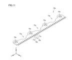
- FIG. 11 is a schematic perspective view showing the appearance of the first rack.
- FIG. 12 is a schematic perspective view showing an enlarged portion of the first rack shown in FIG.
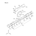
- FIG. 13 is an exploded perspective view of the linear motion guide unit, showing a schematic perspective view of a portion of the cage in an enlarged scale.
- FIG. 14 is a schematic plan view of the pinion cover.
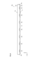
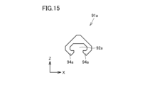
- FIG. 15 is a schematic side view of the pinion cover.
- the linear motion guide unit of the present disclosure includes a first track member extending in a first direction that is a longitudinal direction, and a second track member extending in the first direction and arranged opposite the first track member in a second direction that is a direction perpendicular to the first direction, and the second track member performs linear motion relative to the first track member in the first direction.
- the linear motion guide unit includes a plurality of rollers arranged alternately at intervals in the first direction so that their rolling axes are perpendicular to each other, a cage arranged between the first track member and the second track member in the second direction, a plurality of pockets for accommodating each roller are provided at intervals in the first direction and hold the plurality of rollers, a pinion provided on its outer periphery with a plurality of external teeth, arranged between the first track member and the second track member in the second direction, and rotatably supported, a first rack attached to the outer periphery surface of the first track member and provided with a plurality of first rack teeth that mesh with the external teeth, and a second rack attached to the outer periphery surface of the second track member and provided with a plurality of second rack teeth that mesh with the external teeth.
- the cage includes a roller holding area that holds a plurality of rollers, and a pinion holding area that is disposed adjacent to the roller holding area in the first direction and has a pinion accommodating portion that accommodates a pinion so that the external teeth of the pinion mesh with the second rack teeth.
- the roller holding area and the pinion holding area are integrally configured.
- the linear motion guide unit includes a pinion cover that is attached to the pinion holding area so that the pinion is sandwiched between the pinion holding area and the pinion cover and the external teeth of the pinion mesh with the first rack teeth.
- the linear guide unit described above can prevent misalignment of the retainer that holds the roller by utilizing a pinion, a first rack, and a second rack. This allows for proper guidance of linear motion.
- the external teeth of the pinion are disposed between the first raceway member and the second raceway member, and the first rack and the second rack are attached to the outer circumferential surfaces of the first raceway member and the second raceway member, respectively, so that the pinion can be placed vertically. This allows for a larger contact length between the raceway surface of the raceway member and the roller, and a larger load capacity.
- the retainer includes a roller retaining area that retains the roller, and a pinion retaining area in which a pinion accommodating portion is provided.
- the roller retaining area and the pinion retaining area are integrally configured.
- the pinion holding area may be provided in the center in the first direction.
- a pair of roller holding areas may be provided on both ends of the pinion holding area in the first direction.
- the pinion holding area is provided in the center in the first direction, which is the longitudinal direction, and the cage can be guided in a balanced manner in the longitudinal direction.
- the first and second raceway members can appropriately bear loads without biasing the portion where the roller holding area is provided in the longitudinal direction.
- the pinion cover may be attached to the pinion holding area by snap fitting. In this way, when attaching the pinion cover by sandwiching the pinion, the pinion cover can be attached by utilizing the elastic deformation of the material. This allows for a simpler configuration, which improves assembly and productivity.
- At least one of the first rack and the second rack may be plate-shaped. This simplifies the shape of at least one of the first rack and the second rack, improving productivity.
- At least one of the first rack teeth and the second rack teeth may be provided so as to protrude in the second direction. This makes it easy to mesh at least one of the first rack teeth provided on the first rack or the second rack teeth provided on the second rack with the external teeth of the pinion in the second direction. Therefore, the cage can be guided by appropriately meshing the external teeth of the pinion with the rack teeth while achieving a compact size and a simplified shape.
- the retainer may include a pair of side stays, a plurality of pillars spaced apart from each other in the first direction and connecting the pair of side stays to form a pocket, and a retaining claw that, when viewed from the side where the window of the pocket is open, is connected to one of the side wall surfaces of the pair of side stays and the side wall surface of the pillars and protrudes toward the window, preventing the roller from falling out of the pocket.
- the force pressing the retaining claws can be easily distributed in the first and second directions. This reduces the mechanical load on the retaining claws when the roller is placed in the pocket, reducing the risk of damage to the retaining claws.
- a pair of retaining claws may be provided on one side stay and the other side stay. This can further reduce the mechanical load on each retaining claw, and can further reduce the risk of damage to the retaining claws.
- the retaining claw may include a flat surface that is continuous with the side wall surface of one of the pair of side stays and the side wall surface of the pillar portion. This allows the shape of the retaining claw to be relatively simple, and the area that catches on the roller can be relatively large, greatly reducing the risk of the roller falling out of the pocket.
- the shape of the retaining claws may be an isosceles triangle with equal sides for the portion connected to the side wall surface of the side stay and the portion connected to the side wall surface of the pillar, when viewed from the side where the window portion of the pocket is open. This makes it easier to distribute the load capacity equally to the side stay side and the pillar side when installing the roller in the pocket. This makes it easier to install and improves productivity.
- the first track member may have the same shape as the second track member. This allows the respective parts to be shared, improving productivity.
- the linear motion guide unit of the present disclosure includes a first track member extending in a first direction, which is a longitudinal direction, and a second track member extending in the first direction and arranged opposite the first track member in a second direction, which is a direction perpendicular to the first direction, and the second track member performs linear motion in the first direction relative to the first track member.
- the linear motion guide unit includes a plurality of rollers arranged alternately at intervals in the first direction so that the rolling axes are perpendicular to each other, a cage arranged between the first track member and the second track member in the second direction, a plurality of pockets for accommodating each roller are provided at intervals in the first direction, and holds the plurality of rollers, a pinion provided with a plurality of external teeth on its outer periphery, arranged between the first track member and the second track member in the second direction, and rotatably supported, a first rack attached to the outer periphery of the first track member and provided with a plurality of first rack teeth that mesh with the external teeth, and a second rack attached to the outer periphery of the second track member and provided with a plurality of second rack teeth that mesh with the external teeth.
- the retainer includes a pair of side stays, a number of pillars spaced apart from each other in the first direction and connecting the pair of side stays to form a pocket, and a retaining claw that protrudes toward the window, connecting with the side wall surface of one of the pair of side stays and the side wall surface of the pillars when viewed from the side where the window of the pocket opens, to prevent the roller from falling out of the pocket.
- FIG. 1 is a schematic perspective view of a linear guide unit in the first embodiment of the present disclosure.
- FIG. 2 is a schematic plan view of the linear guide unit shown in FIG. 1.
- FIG. 2 is a view seen in the direction of the arrow II shown in FIG. 1.
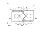
- FIG. 3 is a schematic side view of the linear guide unit shown in FIG. 1.
- FIG. 3 is a view seen in the direction of the arrow III shown in FIG. 1.
- FIG. 4 is a schematic front view of the linear guide unit shown in FIG. 1.
- FIG. 4 is a view seen in the direction of the arrow IV shown in FIG. 1.
- FIG. 5 is a schematic cross-sectional view when cut at the cross section indicated by V-V in FIG. 2.
- FIG. 6 is a schematic perspective view of the linear guide unit 10a in a state where a second track member described later has been removed.
- the direction indicated by the arrow Y is the longitudinal direction
- the direction indicated by the arrow X is the lateral direction
- the direction indicated by the arrow Z is the thickness direction.
- the linear guide unit 10a in the first embodiment includes a first track member 11a, a second track member 12a, a plurality of rollers 13a, a retainer 14a, a pinion 15a, a first rack 16a and a second rack 17a.
- the first track member 11a and the second track member 12a each have a shape extending in a first direction (Y direction) which is a longitudinal direction.
- the first track member 11a and the second track member 12a have the same shape.
- the length in the X direction, the length in the Y direction and the length in the Z direction of the first track member 11a are equal to the length in the X direction, the length in the Y direction and the length in the Z direction of the second track member 12a, respectively.
- the second track member 12a corresponds to a member obtained by inverting the first track member 11a in the Z direction and the X direction, respectively.
- the second track member 12a is disposed opposite the first track member 11a in a second direction (X direction) that is perpendicular to the first direction.
- the linear motion guide unit 10a is a linear motion guide unit in which the second track member 12a performs linear motion relative to the first track member 11a in the first direction.
- the first track member 11a includes a first track surface 21a and a second track surface 22a on which the roller 13a rolls.
- the first track surface 21a and the second track surface 22a are each composed of a plane extending in the longitudinal direction.
- the first track surface 21a is inclined at 45 degrees with respect to the X-Y plane and the Y-Z plane (see Figures 3 and 5 in particular).
- the second track surface 22a is also inclined at 45 degrees with respect to the X-Y plane and the Y-Z plane.
- the second track surface 22a is inclined at 90 degrees with respect to the first track surface 21a.
- a groove-shaped escape portion 23a extending in the Y direction is provided between the first track surface 21a and the second track surface 22a.
- the surface 24a in the X direction of the first track member 11a on the side where the first track surface 21a and the second track surface 22a are provided is parallel to the Y-Z plane and is arranged to face the surface 34a of the second track member 12a described later.
- Both end surfaces 25a in the longitudinal direction of the first track member 11a are provided with circular recesses 26a.
- the first track member 11a is provided with a plurality of circular through holes 27a that penetrate in the thickness direction (Z direction) at intervals in the longitudinal direction. In this embodiment, a total of seven through holes 27a are provided.
- the first track member 11a is provided with a plurality of recesses 29a that are recessed in the thickness direction from one surface 28a in the thickness direction around the area where each through hole 27a is provided as viewed in the thickness direction (Z direction). In this embodiment, a total of seven recesses 29a are also provided.
- the recess 29a includes a wall surface that is semicircular when viewed in the thickness direction, and is configured to reach the other surface 30a in the X direction.
- the first track member 11a is recessed in the thickness direction from the surface 28a and has multiple mounting holes that are used when attaching the first rack 16a. In this embodiment, a total of four mounting holes are provided at intervals in the longitudinal direction. The mounting holes are provided at positions that avoid the recess 29a.
- the configuration of the second track member 12a is the same as that of the first track member 11a. In this way, the respective parts can be shared, and productivity can be improved. That is, the second track member 12a includes a first track surface 31a and a second track surface 32a on which the roller 13a rolls. The second track member 12a is also provided with a recess 33a having a similar configuration to the recess 23a.
- One surface 34a in the X direction of the second track member 12a on the side on which the first track surface 31a and the second track surface 32a are provided is parallel to the Y-Z plane and is arranged to face the surface 24a.
- both end surfaces 35a in the longitudinal direction of the second track member 12a are provided with recesses 36a recessed in the shape of a round hole.
- the second track member 12a is provided with a total of seven multiple round hole-shaped through holes 37a that penetrate the thickness direction at intervals in the longitudinal direction.
- the second track member 12a has a total of seven recesses 39a recessed in the thickness direction from one surface 38a in the thickness direction around the area where each through hole 37a is provided in the thickness direction.
- the recesses 39a include a semicircular wall surface in the thickness direction and are configured to reach the other surface 40a in the X direction.
- the roller 13a is a solid cylinder.
- the roller 13a includes a rolling surface 41a and a pair of end faces 42a.
- the direction connecting the centers of the pair of end faces 42a is the direction of the rolling axis of the roller 13a.
- All of the rollers 13a have the same shape.
- the rollers 13a are alternately arranged at intervals in the longitudinal direction, which is the first direction, so that the rolling axes are perpendicular to each other.
- the linear guide unit 10a includes 22 rollers 13a.
- the retainer 14a has a shape that extends in the longitudinal direction, which is the first direction.
- the retainer 14a holds the multiple rollers 13a so that they can roll.
- the retainer 14a is made of resin.
- the retainer 14a is disposed between the first track member 11a and the second track member 12a in the transverse direction (X direction), which is the second direction.
- FIG. 7 is a schematic perspective view showing an enlarged portion of the retainer 14a.
- FIG. 8 is a schematic cross-sectional view of a portion of the retainer 14a shown in FIG. 7.
- FIG. 8 is a cross-sectional view of a portion of the retainer shown in FIG. 7, cut along a plane including the center of the rolling axis direction of one roller 13a and perpendicular to the rolling axis direction of the roller 13a.
- FIG. 9 is a view of a portion of the retainer 14a shown in FIG. 7, seen from the window portion 45a side of the pocket 44a.
- FIG. 9 is a view from a direction in which the rolling surface 41a of the roller 13a housed in the pocket 44a is exposed.
- FIG. 9 is a view from a direction perpendicular to the rolling axis direction of the roller 13a housed in the pocket 44a.
- the outer shape of the roller 13a housed in the pocket 44a is illustrated by a dashed line in order to facilitate understanding.
- the cage 14a is provided with a plurality of pockets 44a for housing each roller 13a, spaced apart in the longitudinal direction, which is the first direction.
- 22 pockets 44a are provided, corresponding to the number of rollers 13a.
- Adjacent pockets 44a are provided so that the directions in which the rolling surfaces 41a of the housed rollers 13a are exposed are orthogonal to each other.
- the pockets 44a are formed so that the directions in which the window portions 45a through which the rollers 13a are inserted are open are alternately orthogonal to each other in adjacent pockets 44a.
- the retainer 14a includes a pair of side stays 51a, 52a and multiple pillars 53a that connect the pair of side stays 51a, 52a to form a pocket 44a.
- Each of the side stays 51a, 52a is flat and has a through hole 54a in the center. This through hole 54a is used for the flow of lubricant and for removing sink marks in the resin during molding.
- the side stays 51a, 52a are positioned at a 90 degree angle in adjacent pockets 44a.
- the multiple pillars 53a are positioned at intervals in the longitudinal direction (Y direction), which is the first direction.
- the retainer 14a includes retaining claws 55a, 56a that prevent the roller 13a from falling out of the pocket 44a.
- the retaining claws 55a, 56a are provided in pairs on one side stay 51a side and the other side stay 52a side.
- the retaining claw 55a is connected to the side wall surface 57a of the side stay 51a and the side wall surface 59a of the column portion 53a and protrudes toward the window portion 45a side.
- the retaining claw 56a When viewed from the side where one window portion 45a of the pocket 44a opens, the retaining claw 56a is connected to the side wall surface 58a of the side stay 52a and the side wall surface 59a of the column portion 53a and protrudes toward the window portion 45a side.
- the retaining claws 55a, 56a are provided in a tapered shape.
- the retaining claws 55a, 56a each include a flat surface 61a, 62a that is connected to the side wall surfaces 57a, 58a of the pair of side stays 51a, 52a and the pillar portion 53a.
- the shape of the retaining claws 55a, 56a is an isosceles triangle with equilateral sides at the part that is connected to the side wall surfaces 57a, 58a of the side stays 51a, 52a and the part that is connected to the side wall surface 59a of the pillar portion 53a.
- the part of the retaining claw 55a that corresponds to the equilateral side of the isosceles triangle is shown by a broken line in Fig. 9.
- no retaining claw is provided on the pillar portion 53a side that faces in the longitudinal direction.
- retention claws 63a, 64a are formed that protrude toward the window 46a and are connected to the side wall surface 59a of the pillar 53a facing the pillar 53a on which the retention claws 55a, 56a are provided, and to the side wall surfaces 57a, 58a of the pair of side stays 51a, 52a.
- FIG. 10 is a schematic perspective view showing a process for manufacturing a part of the retainer 14a.
- a jig 67a is prepared having flat surfaces 65a, 66a that are recessed in a shape that conforms to the flat surfaces 61a, 62a that constitute the retaining claws 55a, 56a.
- This jig 67a is placed in the pocket 44a, and resin is poured in to perform molding.
- the retaining claws 55a, 56a composed of the flat surfaces 61a, 62a are formed in the portion facing the flat surfaces 65a, 66a.
- the flat surfaces 65a, 66a provided on the jig 67a can be formed by chamfering the corners, so that manufacturing is relatively easy.
- the configuration allows the resin to easily flow in, the retaining claws 55a, 56a of the above shape can be reliably formed even if the size is reduced.
- the pinion 15a has a plurality of external teeth 71a provided on its outer periphery.
- the pinion 15a includes rotating shafts 72a and 73a.
- the pinion 15a is held by a retainer 14a and supported so as to be rotatable about the rotating shafts 72a and 73a.
- FIG. 11 is a schematic perspective view showing the appearance of the first rack 16a.
- FIG. 12 is a schematic perspective view showing an enlarged portion of the first rack 16a shown in FIG. 11.
- the first rack 16a is plate-shaped, specifically, flat.
- the first rack 16a is formed, for example, by punching out a piece of steel plate along the outer shape of the first rack 16a and providing through holes and first rack teeth.
- the first rack 16a is provided with a plurality of through holes 74a, four in this embodiment, that penetrate the thickness direction, i.e., the Z direction, at intervals in the longitudinal direction.
- the first rack 16a is attached to the outer peripheral surface of the first track member 11a, in this embodiment, the surface 28a of the first track member 11a, by bolts 76a using the through holes 74a.
- the first rack 16a is provided with a plurality of notches 75a, three in this embodiment, that are recessed in the X direction.
- the three notches 75a are provided at positions where the through holes 27a and the recesses 29a are exposed when the first rack 16a is attached to the surface 28a of the first track member 11a. By forming these notches 75a, the first track member 11a can be fixed to a predetermined position using the through holes 27a even after the first rack 16a is attached to the surface 28a of the first track member 11a.
- the first rack 16a is provided with a plurality of first rack teeth 77a that mesh with the external teeth 71a of the pinion 15a.
- the plurality of first rack teeth 77a are comb-shaped.
- the plurality of first rack teeth 77a are provided so as to protrude in the X direction, which is the second direction. That is, the first rack teeth 77a are provided so as to protrude in the X direction from the side surface of the first rack 16a in the X direction.
- the first rack teeth 77a are provided so that the width of the side that meshes with the external teeth 71a of the pinion 15a is narrower in the Z direction.
- the groove portion 78a adjacent to the first rack teeth 77a is provided so that the width of the side that meshes with the external teeth 71a of the pinion 15a is wider.
- the side wall surface that constitutes the first rack teeth 77a is tapered when viewed in the X direction.
- the first rack teeth 77a having such a shape are formed, for example, by pressing or etching. With such first rack teeth 77a, the thickness of the first rack 16a is the height of the first rack teeth 77a, so the height of the teeth can be reduced.
- the material of the first rack 16a may be resin, but considering strength, it may be made of metal, for example, steel plate.
- the configuration of the second rack 17a is similar to that of the first rack 16a, so a description thereof will be omitted.
- the second rack 17a includes second rack teeth 79a.
- the second rack 17a is attached and fixed to the second track member 12a.
- FIG. 13 is a schematic perspective view showing an enlarged portion of the retainer 14a in an exploded perspective view of the linear guide unit 10a.
- the retainer 14a includes roller holding areas 81a and 82a that hold a plurality of rollers 13a, and a pinion holding area 83a that holds the pinion 15a.
- a pair of roller holding areas 81a and 82a are provided.
- the roller holding areas 81a and 82a and the pinion holding area 83a are arranged adjacent to each other in the longitudinal direction, which is the first direction.
- the pinion holding area 83a is provided in the center in the first direction.
- the pair of roller holding areas 81a and 82a are provided on both ends of the pinion holding area 83a in the first direction.
- Eleven pockets 44a are provided in each of the roller holding areas 81a and 82a.
- the pinion holding area 83a is provided with a pinion accommodating portion 84a.
- the pinion accommodating portion 84a is recessed from the surface 85a in the Z direction like a groove.
- the pinion accommodating portion 84a is also provided with rotating shaft accommodating portions 86a and 87a that accommodate the rotating shafts 72a and 73a.
- the pinion accommodating portion 84a penetrates in the Z direction except for the area in which the rotating shaft accommodating portions 86a and 87a are provided. Due to the configuration of this pinion accommodating portion 84a, the external teeth 71a of the accommodated pinion 15a are exposed in the Z direction, and the exposed external teeth 71a of the pinion 15a mesh with the second rack teeth 79a of the second rack 17a.
- the pinion holding area 83a is provided with a pair of fitting grooves 88a, 89a.
- the fitting grooves 88a, 89a are provided at a distance in the longitudinal direction so as to sandwich the pinion accommodating portion 84a.
- the fitting grooves 88a, 89a are provided adjacent to each of the pair of roller holding areas 81a, 82a.
- the linear guide unit 10a includes a pinion cover 91a.
- Figure 14 is a schematic plan view of the pinion cover 91a.
- Figure 15 is a schematic side view of the pinion cover 91a. Referring to Figures 14 and 15 together, the pinion cover 91a is attached to the pinion holding area 83a.
- the pinion cover 91a is made of, for example, resin, and can easily elastically deform.
- the pinion cover 91a has a shape extending in the longitudinal direction, and includes a gap portion 92a that accommodates a portion of the pinion holding area 83a, an opening 93a that penetrates in the Z direction, and claw-shaped fitting claws 94a, 95a provided on both longitudinal ends of the pinion cover 91a.
- the pinion cover 91a is attached to the pinion holding area 83a by elastically deforming the fitting claws 94a and 95a to fit into the fitting grooves 88a and 89a.
- the fitting claws 94a and 95a are attached to the pinion holding area 83a by snap fitting.
- a part of the pinion holding area 83a enters the gap 92a, and the pinion 15a is sandwiched between the pinion holding area 83a and the pinion cover 91a.
- the external teeth 71a of the pinion 15a are exposed from the opening 93a.
- the exposed external teeth 71a mesh with the first rack teeth 77a of the first rack 16a.
- the linear motion guide unit 10a configured as above can prevent misalignment of the retainer 14a that holds the roller 13a by utilizing the pinion 15a, first rack 16a, and second rack 17a. This allows for proper guidance of linear motion.
- the external teeth 71a of the pinion 15a are disposed between the first track member 11a and the second track member 12a, and the first rack 16a and the second rack 17a are attached to the outer circumferential surfaces of the first track member 11a and the second track member 12a, respectively, so that the pinion 15a can be placed vertically. This allows for a larger contact length between the track surface of the track member and the roller 13a, and a larger load capacity.
- the retainer 14a includes roller retaining areas 81a and 82a that retain the roller 13a, and a pinion retaining area 83a in which a pinion accommodating portion 84a is provided.
- the roller retaining areas 81a and 82a and the pinion retaining area 83a are integrally configured. In this way, when incorporating a mechanism for retaining the pinion 15a into the retainer 14a, it is not necessary to form a convex portion or a dovetail groove. Therefore, work such as damaging the convex portion or fitting it into the dovetail groove does not occur, and productivity can be improved.
- the pinion holding area 83a is provided in the center in the first direction.
- the roller holding areas 81a, 82a are provided in pairs on both ends of the pinion holding area 83a in the first direction. Therefore, by providing the pinion holding area 83a in the center in the first direction, which is the longitudinal direction, the cage 14a can be guided in a balanced manner in the longitudinal direction.
- the first track member 11a and the second track member 12a can appropriately bear the load without biasing the portions where the roller holding areas 81a, 82a are provided in the longitudinal direction.
- the pinion cover 91a is attached to the pinion holding area 83a by snap fitting. Therefore, when attaching the pinion cover 91a by sandwiching the pinion 15a, the pinion cover 91a can be attached by utilizing the elastic deformation of the material. This allows for a simpler configuration, which improves assembly and productivity.
- both the first rack 16a and the second rack 17a are plate-shaped. Therefore, the shape of both the first rack 16a and the second rack 17a can be simplified, and productivity can be improved.
- both the first rack teeth 77a and the second rack teeth 79a are provided to protrude in the second direction. This makes it easy to mesh both the first rack teeth 77a provided on the first rack 16a and the second rack teeth 79a provided on the second rack 17a with the external teeth 71a of the pinion 15a in the second direction. This allows the cage 14a to be guided by appropriately meshing the external teeth 71a of the pinion 15a with the rack teeth while achieving a compact size and a simplified shape.
- the retainer 14a includes a pair of side stays 51a, 52a, a plurality of pillars 53a that are spaced apart from each other in the first direction and connect the pair of side stays 51a, 52a to form the pocket 44a, and retaining claws 55a, 56a that are connected to the side wall surfaces 57a, 58a of the pair of side stays 51a, 52a and the side wall surface 59a of the pillars 53a when viewed from the side where the window portion 45a of the pocket 44a is opened, and protrude toward the window portion 45a, preventing the roller 13a from falling out of the pocket 44a.
- the side stays 51a, 52a are easily bent, particularly in the direction indicated by force F3, and can be deformed with a relatively small force. Therefore, the mechanical load on the retaining claws 55a, 56a when the roller 13a is stored can be reduced, and the risk of damage to the retaining claws 55a, 56a can be reduced.
- the retaining claws 55a, 56a are provided in pairs on one side stay 51a and the other side stay 52a. This further reduces the mechanical load on each of the retaining claws 55a, 56a, and further reduces the risk of damage to the retaining claws 55a, 56a.
- the retaining claws 55a, 56a include flat surfaces 61a, 62a that are continuous with the side wall surfaces 57a, 58a of the pair of side stays 51a, 52a and the side wall surface 59a of the pillar portion 53a. This allows the shape of the retaining claws 55a, 56a to be relatively simple, and the area that catches on the roller 13a to be relatively large, greatly reducing the risk of the roller 13a falling off the pocket 44a.
- the shape of the retaining claws 55a, 56a when viewed from the side where the window portion 45a of the pocket 44a is open, is an isosceles triangle with equilateral sides at the portions connected to the side wall surfaces 57a, 58a of the side stays 51a, 52a and the portion connected to the side wall surface 59a of the pillar portion 53a. Therefore, when the roller 13a is assembled into the pocket 44a, it becomes easier to distribute the load capacity equally to the side stays 51a, 52a and the pillar portion 53a. This improves assembly ease and productivity.
- the linear motion guide unit 10a disclosed herein comprises a first track member 11a extending in a first direction, which is the longitudinal direction, and a second track member 12a extending in the first direction and arranged opposite the first track member 11a in a second direction, which is a direction perpendicular to the first direction, and the second track member 12a performs linear motion relative to the first track member 11a in the first direction.
- the linear motion guide unit 10a includes: a plurality of rollers 13a arranged alternately at intervals in a first direction so that their rolling axes are perpendicular to each other; a cage 14a arranged between the first track member 11a and the second track member 12a in the second direction, with a plurality of pockets 44a for accommodating each of the rollers 13a provided at intervals in the first direction and holding the plurality of rollers 13a; a pinion 15a provided on its outer periphery, arranged between the first track member 11a and the second track member 12a in the second direction and rotatably supported; a first rack 16a attached to the outer periphery of the first track member 11a and provided with a plurality of first rack teeth 77a that mesh with the external teeth 71a; and a second rack 17a attached to the outer periphery of the second track member 12a and provided with a plurality of second rack teeth 79a that mesh with the external teeth 71a.
- the retainer 14a includes a pair of side stays 51a, 52a, a plurality of pillars 53a that are spaced apart from each other in the first direction and connect the pair of side stays 51a, 52a to form a pocket 44a, and retaining claws 55a, 56a that, when viewed from the side where the window portion 45a of the pocket 44a opens, are connected to one of the side wall surfaces 57a, 58a of the pair of side stays 51a, 52a and the side wall surface 59a of the pillars 53a and protrude toward the window portion 45a, preventing the roller 13a from falling out of the pocket 44a.
- the shape is an isosceles triangle, but the shape is not limited to this, and may be a triangle whose three sides have different lengths, or a polygon.
- the wall surface constituting the retaining claw may be concave in an arc shape or protrude in an arc shape when viewed from the side where the window portion of the pocket is opened.
- a pair of retaining claws are provided, but this is not limiting, and it is also possible to provide only one retaining claw. In this case, by making the amount of protrusion larger than when a pair is provided, it is possible to more reliably prevent the roller from falling out of the pocket.
- the pinion cover is attached to the pinion holding area by snap fitting, but this is not limiting, and the pinion cover may be attached to the pinion holding area using screws or the like. Also, in the snap fit structure, fitting claws may be provided in the pinion holding area, and fitting grooves may be provided in the pinion cover.
- 10a linear motion guide unit 11a first track member, 12a second track member, 13a roller, 14a retainer, 15a pinion, 16a first rack, 17a second rack, 21a, 31a first track surface, 22a, 32a second track surface, 23a, 33a escape portion, 24a, 28a, 30a, 34a, 38a, 40a, 85a surface, 25a, 35a, 42a end surface, 26a, 29a, 36a, 39a recess, 27a, 37a, 54a, 74a through hole, 41a rolling surface, 44a pocket, 45a, 46a window portion, 51a, 52a side stay , 53a pillar portion, 55a, 56a, 63a, 64a retaining claws, 57a, 58a, 59a side wall surface, 61a, 62a, 65a, 66a flat surface, 67a jig, 71a external teeth, 72a, 73a rotating shaft, 75a notch, 76a bolt, 77a first rack tooth, 78
Landscapes
- Engineering & Computer Science (AREA)
- General Engineering & Computer Science (AREA)
- Mechanical Engineering (AREA)
- Bearings For Parts Moving Linearly (AREA)
Priority Applications (4)
| Application Number | Priority Date | Filing Date | Title |
|---|---|---|---|
| JP2025527265A JP7775533B2 (ja) | 2023-06-20 | 2023-06-20 | 直動案内ユニット |
| CN202380099568.0A CN121399387A (zh) | 2023-06-20 | 2023-06-20 | 直动引导单元 |
| DE112023006384.2T DE112023006384T5 (de) | 2023-06-20 | 2023-06-20 | Linearbewegungsführungseinheit |
| PCT/JP2023/022764 WO2024261863A1 (ja) | 2023-06-20 | 2023-06-20 | 直動案内ユニット |
Applications Claiming Priority (1)
| Application Number | Priority Date | Filing Date | Title |
|---|---|---|---|
| PCT/JP2023/022764 WO2024261863A1 (ja) | 2023-06-20 | 2023-06-20 | 直動案内ユニット |
Publications (1)
| Publication Number | Publication Date |
|---|---|
| WO2024261863A1 true WO2024261863A1 (ja) | 2024-12-26 |
Family
ID=93935127
Family Applications (1)
| Application Number | Title | Priority Date | Filing Date |
|---|---|---|---|
| PCT/JP2023/022764 Ceased WO2024261863A1 (ja) | 2023-06-20 | 2023-06-20 | 直動案内ユニット |
Country Status (4)
| Country | Link |
|---|---|
| JP (1) | JP7775533B2 (https=) |
| CN (1) | CN121399387A (https=) |
| DE (1) | DE112023006384T5 (https=) |
| WO (1) | WO2024261863A1 (https=) |
Citations (4)
| Publication number | Priority date | Publication date | Assignee | Title |
|---|---|---|---|---|
| JP2003262224A (ja) * | 2002-03-11 | 2003-09-19 | Nippon Skf Kk | 直動案内装置 |
| EP2397712A1 (de) * | 2010-06-21 | 2011-12-21 | Aktiebolaget SKF | Linearführung mit zwangsgeführtem Käfig |
| JP2021139442A (ja) * | 2020-03-05 | 2021-09-16 | Thk株式会社 | 運動案内装置 |
| JP2022116471A (ja) * | 2021-01-29 | 2022-08-10 | Thk株式会社 | 直動案内装置 |
-
2023
- 2023-06-20 JP JP2025527265A patent/JP7775533B2/ja active Active
- 2023-06-20 WO PCT/JP2023/022764 patent/WO2024261863A1/ja not_active Ceased
- 2023-06-20 DE DE112023006384.2T patent/DE112023006384T5/de active Pending
- 2023-06-20 CN CN202380099568.0A patent/CN121399387A/zh active Pending
Patent Citations (4)
| Publication number | Priority date | Publication date | Assignee | Title |
|---|---|---|---|---|
| JP2003262224A (ja) * | 2002-03-11 | 2003-09-19 | Nippon Skf Kk | 直動案内装置 |
| EP2397712A1 (de) * | 2010-06-21 | 2011-12-21 | Aktiebolaget SKF | Linearführung mit zwangsgeführtem Käfig |
| JP2021139442A (ja) * | 2020-03-05 | 2021-09-16 | Thk株式会社 | 運動案内装置 |
| JP2022116471A (ja) * | 2021-01-29 | 2022-08-10 | Thk株式会社 | 直動案内装置 |
Also Published As
| Publication number | Publication date |
|---|---|
| CN121399387A (zh) | 2026-01-23 |
| DE112023006384T5 (de) | 2026-03-26 |
| JPWO2024261863A1 (https=) | 2024-12-26 |
| JP7775533B2 (ja) | 2025-11-25 |
Similar Documents
| Publication | Publication Date | Title |
|---|---|---|
| JP4568453B2 (ja) | 運動案内装置 | |
| EP0838602B1 (en) | Linear roller guide | |
| US7229215B2 (en) | Double-split cage | |
| JP3878068B2 (ja) | デフレクタ式ボールスクリュー装置及びその製造方法 | |
| CN118946746A (zh) | 减速器 | |
| JP2021188687A (ja) | ボールねじ装置 | |
| WO2024261863A1 (ja) | 直動案内ユニット | |
| US3356428A (en) | Roller bearing cage | |
| US4692037A (en) | Roller bearing for an infinite rectilinear motion | |
| WO2005066511A1 (ja) | ボールスプライン | |
| JP2006275219A (ja) | 一方向ローラクラッチ | |
| JP2907524B2 (ja) | 転がり軸受の保持器 | |
| KR20250092093A (ko) | 롤링 요소 유지기, 슬라이딩 부재 및 유한 행정 슬라이드 레일 | |
| US3054648A (en) | Sliding roller bearing | |
| JP3371035B2 (ja) | ボールスプライン | |
| JP2612965B2 (ja) | リニアベアリング | |
| JP3529131B2 (ja) | ベアリング装置 | |
| US4620751A (en) | Roller bearing for linear motion | |
| CN114945756A (zh) | 直动引导轴承 | |
| JPH0522414Y2 (https=) | ||
| JP2600979Y2 (ja) | 直動ころがり案内軸受 | |
| JP6033125B2 (ja) | 転がり案内装置 | |
| JP3670826B2 (ja) | 転動体連結体 | |
| WO2024004233A1 (ja) | 直動装置 | |
| WO2025163989A1 (ja) | 直動案内ユニットおよびアダプタ |
Legal Events
| Date | Code | Title | Description |
|---|---|---|---|
| 121 | Ep: the epo has been informed by wipo that ep was designated in this application |
Ref document number: 23942300 Country of ref document: EP Kind code of ref document: A1 |
|
| ENP | Entry into the national phase |
Ref document number: 2025527265 Country of ref document: JP Kind code of ref document: A |
|
| WWE | Wipo information: entry into national phase |
Ref document number: 2025527265 Country of ref document: JP |
|
| WWE | Wipo information: entry into national phase |
Ref document number: 112023006384 Country of ref document: DE |
|
| WWE | Wipo information: entry into national phase |
Ref document number: 11202508089R Country of ref document: SG |
|
| WWP | Wipo information: published in national office |
Ref document number: 11202508089R Country of ref document: SG |
|
| WWP | Wipo information: published in national office |
Ref document number: 112023006384 Country of ref document: DE |