WO2024261846A1 - 車両管理システム - Google Patents
車両管理システム Download PDFInfo
- Publication number
- WO2024261846A1 WO2024261846A1 PCT/JP2023/022704 JP2023022704W WO2024261846A1 WO 2024261846 A1 WO2024261846 A1 WO 2024261846A1 JP 2023022704 W JP2023022704 W JP 2023022704W WO 2024261846 A1 WO2024261846 A1 WO 2024261846A1
- Authority
- WO
- WIPO (PCT)
- Prior art keywords
- vehicle
- mounted device
- relay
- unit
- transmits
- Prior art date
- Legal status (The legal status is an assumption and is not a legal conclusion. Google has not performed a legal analysis and makes no representation as to the accuracy of the status listed.)
- Ceased
Links
Images



Classifications
-
- B—PERFORMING OPERATIONS; TRANSPORTING
- B60—VEHICLES IN GENERAL
- B60R—VEHICLES, VEHICLE FITTINGS, OR VEHICLE PARTS, NOT OTHERWISE PROVIDED FOR
- B60R25/00—Fittings or systems for preventing or indicating unauthorised use or theft of vehicles
- B60R25/01—Fittings or systems for preventing or indicating unauthorised use or theft of vehicles operating on vehicle systems or fittings, e.g. on doors, seats or windscreens
Definitions
- the present invention relates to a vehicle management system, and in particular to a vehicle management system that allows users to control the start and stop of their vehicles based on commands from a management server.
- a vehicle control system is a system that allows the starting and stopping of a vehicle, such as an automobile, driven by a user to be controlled externally, and allows the starting and stopping of the vehicle to be safely controlled externally when the user is forced to stop driving the vehicle for various reasons.
- This technology does indeed make it possible to configure a device that can lock and unlock vehicle doors without going through the vehicle's ECU or CAN, but there are major issues with the security of the relay itself, making it possible for unauthorized operation to easily control the relay to lock and unlock the doors, and so the technology cannot be considered sufficient from a security standpoint.
- a system that controls the starting and stopping of vehicles based on commands from a management server is required to prevent unauthorized use from the standpoint of reliability, safety, and crime prevention. Therefore, there was a need for the development of a vehicle management system that would enable control of the starting and stopping of vehicles owned by users based on commands from the management server, and that was equipped with a relay with a structure that allowed it to be energized when it received an external instruction to allow it to be energized.
- the present invention aims to provide a vehicle management system that, in particular, allows the start and stop of a vehicle owned by a user to be controlled by commands from a management server, and has a relay with a structure that allows it to be energized when it receives an external instruction to allow it to be energized, thereby improving security functions.
- the vehicle management system of the present invention is a vehicle management system for managing the startup status of a vehicle from a remote location, and comprises a management server that manages the startup status of the vehicle and issues instructions to start and stop the vehicle, a GPS receiver installed in the vehicle, and a vehicle-mounted device that is installed in the vehicle and transmits the startup status and position information of the vehicle to the management server and controls the startup and stopping of the vehicle, the vehicle-mounted device controls a relay that switches the startup and stopping of the drive device of the vehicle, the management server determines whether or not to start or stop the vehicle based on the startup information and position information of the vehicle transmitted from the vehicle-mounted device, transmits a command to start or stop the vehicle to the vehicle-mounted device, and the vehicle-mounted device transmits a signal to the relay to perform set processing or reset processing of the relay.
- the relay also includes an electromagnetic section having an electromagnet, a contact section that brings a movable contact into contact with a fixed contact and separates it from each other when electricity is applied to the electromagnet, a control section that receives the signal, analyzes the received signal, and determines whether electricity should be applied to the electromagnetic section based on the analysis results, and a power supply switching section that selects or switches between power to the electromagnetic section or power to the contact section and supplies power to the control section.
- an electromagnetic section having an electromagnet
- a contact section that brings a movable contact into contact with a fixed contact and separates it from each other when electricity is applied to the electromagnet
- a control section that receives the signal, analyzes the received signal, and determines whether electricity should be applied to the electromagnetic section based on the analysis results
- a power supply switching section that selects or switches between power to the electromagnetic section or power to the contact section and supplies power to the control section.
- the control unit includes a receiving unit for receiving the signal from the vehicle-mounted device, and the receiving unit receives and analyzes the power-on permission signal from the vehicle-mounted device to determine whether or not to energize the electromagnetic unit, and then energizes the electromagnetic unit.
- the power supply switching unit is configured to be connected to both the terminal on the electromagnetic unit side and the terminal on the contact unit side, and in order to ensure power supply for the control unit, when there is no current between the terminals on the electromagnetic unit side, the power supply switching unit obtains power from the terminal on the contact unit side and supplies power to the control unit for performing the control function, and when there is current between the terminals on the electromagnetic unit side, the power supply switching unit obtains power from the terminal on the electromagnetic unit side and supplies power to the control unit for performing the control function.
- the electromagnetic portion has a latching structure consisting of a set coil and a reset coil, and when current is passed through the set coil, current is ensured in the electromagnetic portion and the contact portions are brought into contact, and when current is passed through the reset coil, current is released in the electromagnetic portion and the contact portions are separated.
- the electromagnetic portion is also configured to have a latching structure that controls energization/de-energization of the electromagnetic portion by reversing polarity, thereby controlling contact/separation of the contact portion.
- the management server is equipped with a user database that registers and holds information related to the user of the vehicle, and the user database includes storage location information of the vehicle.
- the management server is configured to obtain information that the vehicle has been parked for a specified period of time within a specified range from the storage location registered in the storage location information, determine whether or not to start or stop the vehicle, and transmit a start command or stop command for the vehicle to the vehicle-mounted device.
- the management server is configured to acquire location information of the vehicle when a disaster occurs, and upon acquiring information that the vehicle is located in a specified disaster area, release the control of the relay by the vehicle-mounted device.
- the relay is equipped with a measuring means for measuring the resistance value of each device connected to the vehicle, and when it detects that the resistance value is outside a predetermined range, it transmits an alert signal to the vehicle-mounted device, and the vehicle-mounted device transmits alert information to the management server.
- the vehicle management system is configured to include a mobile communication terminal capable of communicating with the vehicle-mounted device, and to include a selection means for selectively switching between communication between the management server and the vehicle-mounted device and communication between the mobile communication terminal and the vehicle-mounted device.
- the mobile communication terminal when it approaches the vehicle, it transmits a command to start the vehicle to the vehicle-mounted device, and then the vehicle-mounted device transmits a signal to the relay to perform set processing of the relay, and when the mobile communication terminal moves away from the vehicle, it transmits a command to stop the vehicle to the vehicle-mounted device, and then the vehicle-mounted device transmits a signal to the relay to perform reset processing of the relay.
- the vehicle-mounted device is also configured to include an acceleration sensor, and when the acceleration sensor detects acceleration exceeding a predetermined value, the vehicle-mounted device transmits a signal to the relay to perform a reset process of the relay.
- the management server is configured to include a theft detection means for transmitting a vehicle stop command and an alert command to the vehicle mounted device if it detects that the vehicle has been stopped for a certain period of time from the GPS information of the vehicle received from the vehicle mounted device and cannot obtain information from the vehicle mounted device within a specified period of time.
- the vehicle-mounted device detects whether or not power is being supplied to the electromagnet of the relay and transmits the detection result to the management server, and the management server determines whether or not the vehicle can be stopped based on whether or not power is being supplied to the electromagnet, and transmits a command to stop the vehicle to the vehicle-mounted device.
- the present invention has the configuration as described above in detail and thus has the following effects.
- the management server is configured to control the vehicle-mounted device installed in the vehicle equipped with a GPS receiver, so it is possible to control the vehicle-mounted device while checking the vehicle's position information and switch between starting and stopping the vehicle's drive system.
- the control unit in the relay mounted on the vehicle, it is possible to ensure security by controlling whether or not electricity is passed to the electromagnetic unit.
- a power supply switching unit it is possible to switch the power supply of the control unit between the electromagnetic unit side and the contact unit side, making it possible to reliably secure the power supply for the control unit.
- control unit of the relay is configured to include a receiving unit, it is possible for the control unit to control the energization of the relay upon receiving a power-on permission signal from the server via the vehicle-mounted device, and security can be ensured by operating the relay by receiving a legitimate signal.
- the electromagnetic part of the relay is configured with a set coil and a reset coil, which enables latching. This eliminates the need to constantly energize the electromagnetic part, and enables highly stable relay control by eliminating power loss or shortage.
- the contact/separation with the contact part is controlled by reversing the polarity of the electromagnetic part of the relay, latching can be performed, eliminating the need to constantly energize the electromagnetic part, and enabling highly stable relay control by eliminating power loss or shortage.
- the management server is configured to hold storage location information for each vehicle, it is possible to obtain the storage location information and current location information of the vehicle and then issue a start command or stop command for the vehicle.
- the management server acquires the vehicle's location information, and when it confirms that the vehicle is in the disaster area, it emergency releases the control of the relay, so that it is possible to avoid a situation in which the vehicle cannot be used when a disaster occurs.
- the relay is configured to include a measuring means for measuring the resistance value of each device connected to the vehicle, so that it is possible to detect abnormalities such as vehicle theft from the resistance value and issue an alert.
- the vehicle management system is configured to include a mobile communication terminal, it is possible to access the vehicle-mounted device from the mobile communication terminal, and it is possible to issue a start command or a stop command to the vehicle using the mobile communication terminal even in an environment where communication is not possible.
- the system is designed to switch between starting and stopping commands for the vehicle depending on the distance between the mobile communication terminal and the vehicle-mounted device, so that simply by holding the mobile communication terminal, it is possible to easily start and stop commands for the vehicle, ensuring a higher level of security.
- the vehicle-mounted device is configured to include an acceleration sensor, so that it is possible to detect a vehicle accident and transmit a vehicle stop command to prevent a vehicle fire or the like.
- the management server is configured to include a theft detection means, so that the theft of the vehicle can be detected based on GPS information and information from the vehicle-mounted device.
- the management server is configured to transmit a command to stop the vehicle based on the presence or absence of power being supplied to the electromagnet, it is possible to detect when the vehicle has stopped and safely perform the process of stopping the vehicle.
- Fig. 1 is a conceptual diagram of the vehicle management system according to the present invention
- Fig. 2 is a conceptual diagram of a relay
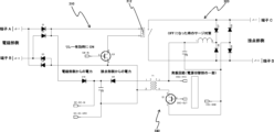
- Fig. 3 is a circuit diagram showing the mechanism of the power supply switching operation of the relay
- Fig. 4 is a circuit diagram of a relay using a latching structure.
- the vehicle management system 1 of the present invention is a system that comprises a management server 100, a vehicle mounted device 200, and a relay 300, and manages the startup status of a vehicle 10 from a remote location. It enables the startup and shutdown of a vehicle 10 owned by a user to be controlled by commands from the management server 100, and is a vehicle management system that has improved security functions by including a relay 300 that is structured so that it can be energized when it receives an external instruction to allow it to be energized.
- the vehicle 10 is mainly composed of a regular automobile, but it may include any type of automobile, such as a motorcycle, truck, or bus, and may also include heavy machinery.
- the management server 100 is a server that manages the startup status of the vehicle 10 and issues instructions to start and stop the vehicle 10. As shown in FIG. 1, the management server 100 is installed at a location separate from the vehicle 10 and is connected to the vehicle 10 via a network.
- the management server 100 may be configured as a single server, or may be configured as a group of multiple servers to distribute processing. Note that communication between the management server 100 and the vehicle 10 is performed using a public line, and in this embodiment, Sigfox (registered trademark) is used, but this is not limited to this.
- the GPS receiver G is a device that receives signals from GPS satellites and is capable of determining its own position information (latitude and longitude), and in this embodiment is installed in the vehicle 10.
- the vehicle mounted device 200 is a component that is installed in the vehicle 10 and has the function of transmitting the startup status and location information of the vehicle 10 to the management server 100. After obtaining the current location information of the vehicle 10 using the GPS receiver G, the vehicle mounted device 200 (described below) transmits this information to the management server 100. The vehicle mounted device 200 also has the function of controlling the startup and shutdown of the vehicle 10 based on commands transmitted from the management server 100, etc.
- the vehicle-mounted device 200 is configured to control a relay 300 that switches between starting and stopping a drive device (not shown) of the vehicle 10. By switching between set and reset of the relay 300, it becomes possible to easily control the starting and stopping of the vehicle 10.
- the management server 100 is configured to determine whether or not to start or stop the vehicle 10 based on the start information and position information of the vehicle 10 transmitted from the vehicle-mounted device 200. When starting or stopping the vehicle 10, which needs to be processed, it is necessary to ensure the safety of the vehicle 10 when performing the processing. For example, performing a stop process while the vehicle 10 is in operation (moving) creates the risk of an accident occurring.
- the management server 100 is configured to determine safety, and if it is confirmed that it is safe, to transmit a start command BC or a stop command SC for the vehicle 10 to the vehicle-mounted device 200.
- the vehicle-mounted device 200 which receives the start command BC or the stop command SC of the vehicle 10, transmits a signal S to the relay 300 to perform a set process or a reset process of the relay 300.
- the relay 300 is composed of an electromagnetic part 310, a contact part 320, a control part 330, and a power supply switching part 340, and is a relay with a security function that makes it possible to switch between energized and de-energized states on the contact part 320 side by controlling the energization of the electromagnetic part 310 based on a signal S from the vehicle-mounted device 200.
- the electromagnetic part 310 is a member for switching between energized and de-energized states on the contact part 320 side, and as shown in FIG. 2, in this embodiment, it is provided with an electromagnet 312 having a coil.
- the electromagnet 312 When electricity is applied between the terminals (terminals A and B) on the electromagnetic part 310 side, the electromagnet 312 provided between the terminals generates a magnetic force.
- the contact unit 320 is a member for supplying power to the various electronic components of the vehicle 10, and in this embodiment, as shown in FIG. 2, includes a movable contact 322 and a fixed contact 324.
- a magnetic force is generated by energizing the electromagnet 312 of the electromagnetic unit 310
- the movable contact 322 comes into contact with the fixed contact 324, causing electricity to flow between the terminals (terminals C and D) on the contact unit 320 side, and power is supplied to the various electronic components of the vehicle 10.
- electricity to the electromagnetic unit 310 is cut off, the contact between the movable contact 322 and the fixed contact 324 is released, electricity is cut off between terminals C and D, and the supply of power to the various electronic components of the vehicle 10 is stopped.
- the relay 300 is configured to include a control unit 330.
- the control unit 330 is a member for controlling the flow of electricity between the terminals (terminals A and B) on the electromagnetic unit 310 side.
- the control unit 330 receives a signal S from the vehicle-mounted device 200 and analyzes the signal S.
- the control unit 330 analyzes whether the received signal S is an authentic signal, and if it is authentic, starts the flow of electricity between the terminals (terminals A and B) on the electromagnetic unit 310 side.
- the movable contact 322 comes into contact with the fixed contact 324, and electricity flows between the terminals (terminals C and D) on the contact unit 320 side, making it possible to pass electricity through various electronic components of the vehicle 10.
- the vehicle 10 equipped with the relay 300 is configured to be started and stopped from the outside by authenticating the signal S, which makes it possible to maintain security.
- the relay 300 further includes a power supply switching unit 340 as shown in FIG. 2.
- the power supply switching unit 340 is a member for securing power for the control unit 330, and in this embodiment, is configured to select or switch between power to the electromagnetic unit 310 (power applied between terminals on the electromagnetic unit 310 side) and power to the contact unit 320 (power applied between terminals on the contact unit 320 side) as the power for the control unit 330, and supply power as the power supply for the control unit 330.
- the control unit 330 is configured to include a receiving unit 332.
- the receiving unit 332 is a member for receiving a signal S emitted from the vehicle-mounted device 200.
- the receiving unit 332 receives and analyzes the power supply permission signal from the vehicle-mounted device 200 to determine whether or not power can be supplied to the electromagnetic unit 310.
- the control unit 330 controls the power supply to the electromagnetic unit 310.
- control unit 330 and the vehicle-mounted device 200 are connected via wireless communication such as Bluetooth (registered trademark) encrypted communication or Wi-Fi, but this is not limited to this, and it is of course possible to connect them directly via a cord or the like.
- wireless communication such as Bluetooth (registered trademark) encrypted communication or Wi-Fi, but this is not limited to this, and it is of course possible to connect them directly via a cord or the like.
- the power supply switching unit 340 is connected to both the terminals on the electromagnetic unit 310 side (terminals A and B) and the terminals on the contact unit 320 side (terminals C and D).
- the power supply switching unit 340 obtains power from the terminals on the contact unit 320 side and supplies power to the control unit 330 to perform its control functions. This power is weak, so it does not have a significant effect on the various electronic components of the vehicle 10 that use the relay 300.
- the power supply switching unit 340 obtains power from the terminals on the electromagnetic unit 310 side, thereby supplying power to the control unit 330 to perform the control function.
- This configuration makes it possible to select or switch the power source for the control unit 330 between the electromagnetic unit 310 side and the contact unit 320 side, making it possible to reliably secure the power source for the control unit 330.
- the relay 300 can be configured to have a latching structure using a set coil 314 and a reset coil 316.
- the electromagnetic part 310 When current is applied to the set coil 314, the electromagnetic part 310 is energized and the contact parts 320 are brought into contact, and when current is applied to the reset coil 316, the electromagnetic part 310 is de-energized and the contact parts 320 are separated.
- the driving power for the relay 300 is obtained from the contact unit 320 side, and the control of the current supply to the set coil 314 and reset coil 316 is performed by the control unit 330.
- the electromagnetic part 310 can be configured with a latching structure that controls contact/separation with the contact part 320 by reversing the polarity to energize/de-energize the electromagnetic part 310.
- the above configuration eliminates the need to constantly supply power to the electromagnetic section 310, making it possible to avoid unauthorized power loss in various electronic components of the vehicle 10 due to power loss on the electromagnetic section 310 side, and power shortages due to power usage on the electromagnetic section 310 side, and makes it possible to provide a relay 300 that is safe and convenient for controlling the start and stop of the vehicle 10.
- control unit 330 can control the separation of the contacts 320.
- the relay 300 By configuring the relay 300 as described above, it is possible to prevent fraudulent acts, such as starting the vehicle 10 while the vehicle 10 is in the process of stopping, and to provide a vehicle management system 1 with high security.
- the management server 100 is configured to include a user database 110.
- the user database 110 is a database that registers and holds information related to users who own, rent, or lease vehicles 10, and the information related to users includes storage location information P of the vehicles 10.
- the management server 100 acquires information that the vehicle 10 has been parked for a specified period of time within a specified range of a storage location registered in the storage location information P. This makes it possible to determine whether the vehicle 10 is running or stopped. The management server 100 then determines whether the vehicle 10 can be started or stopped based on the acquired information, and transmits a start command BC or a stop command SC for the vehicle 10 to the vehicle mounted device 200. This makes it possible to avoid a dangerous situation that would occur if the vehicle 10 were stopped while the vehicle 10 is running or stopped at a traffic light, for example, and makes it possible to safely issue a start command BC or a stop command SC for the vehicle 10.
- the management server 100 when the management server 100 restricts the functions of the vehicle 10, such as the start command BC or the stop command SC, it can be configured to automatically issue the start command BC or the stop command SC of the vehicle 10 when it is confirmed that the vehicle is present (parked) within a given range from a pre-registered vehicle storage location P for a given set period of time.
- the user can also specify a date and time to make a reservation.
- the functional restriction status related to the start command BC or the stop command SC of the vehicle 10 can be obtained from the vehicle mounted device 200 at any time.
- the management server 100 can be configured to acquire location information of the vehicle 10 when a disaster occurs, and detect whether or not it is located in a specified disaster area. If it acquires that the vehicle 10 is located in a specified disaster area, the management server 10 is configured to release the control of the relay 300 by the vehicle mounted device 200. This makes it possible to release the stop command SC for the vehicle 10 that cannot be moved when a disaster occurs, as a result of which it becomes possible to prevent a dangerous situation in which the vehicle 10 cannot be used when a disaster occurs.
- the relay 300 can be configured to include a measuring means 350.
- the measuring means 350 is a device that measures the resistance value of each device, such as an electronic component, connected to the vehicle 10. The measured resistance value is transmitted to the vehicle-mounted device 200 as numerical data. If the measuring means 350 detects that the resistance value is outside a predetermined range, it transmits an alert signal to the vehicle-mounted device 200, which then transmits alert information to the management server 100. With this configuration, it is possible to detect abnormalities, such as theft of the vehicle 10, from the resistance value, and it is possible to quickly obtain the abnormal state of the vehicle 10 and reduce the risk of damage, theft, etc., of the vehicle 10.
- the measuring means 350 is configured to be equipped in the relay 300, but this is not limited to this, and it may also be configured to be equipped in the vehicle-mounted device 200.
- the vehicle management system 1 can be configured to include a mobile communication terminal 400, as shown in FIG. 1.
- the mobile communication terminal 400 is a small, portable terminal held by the user that can communicate with the vehicle-mounted device 200.
- a smartphone or a small tablet machine is used, but the present invention is not limited to this.
- any suitable device that is portable and capable of communication such as a smart key for the vehicle 10, can be selected and used.
- the vehicle management system 1 can also be configured to include a selection means 500.
- the selection means 500 is a means for selectively switching between communication between the management server 100 and the vehicle-mounted device 200 and communication between the mobile communication terminal 400 and the vehicle-mounted device 200. Normally, the vehicle-mounted device 200 is set to communicate with the management server 100, but if the vehicle 10 is located in a position where communication is not possible, the management server 100 cannot transmit the start command BC or stop command SC for the vehicle 10.
- the selection means 500 switches communication, so that the vehicle-mounted device 200 can communicate with the mobile communication terminal 400, and the mobile communication terminal 400 can transmit the start command BC or stop command SC for the vehicle 10 to the vehicle-mounted device 200 instead of the management server 100, making it possible to perform operation management of the vehicle 10 even in an environment where communication is not possible.
- the mobile communication terminal 400 of the vehicle management system 1 can be configured to transmit a start command BC for the vehicle 10 to the vehicle mounted device 200 when approaching the vehicle 10, and the vehicle mounted device 200 transmits a signal to the relay 300 to perform a set process of the relay 300.
- the mobile communication terminal 400 can be configured to transmit a stop command SC for the vehicle 10 to the vehicle mounted device 200, and the vehicle mounted device 200 transmits a signal to the relay 300 to perform a reset process of the relay 300.
- This configuration makes it possible to switch between sending the start command BC and the stop command SC of the vehicle 10 depending on the distance between the mobile communication terminal 400 and the vehicle mounted device 200. Simply by holding the mobile communication terminal 400, the start command BC and the stop command SC of the vehicle 10 can be easily sent, ensuring a higher level of security.
- the vehicle-mounted device 200 can be configured to include an acceleration sensor 210.
- the acceleration sensor 210 is a component that detects the acceleration of an object, and in this embodiment, when the acceleration sensor 210 detects acceleration exceeding a predetermined value, the vehicle-mounted device 200 transmits a signal to the relay 300 to perform a reset process on the relay 300.
- the management server 100 can be configured to include a theft detection means 120.
- the theft detection means 120 is a means for detecting that the vehicle 10 has been stopped for a certain period of time from the GPS information of the vehicle 10 received from the vehicle mounted device 200, and then transmitting a stop command SC and an alert command AC for the vehicle 10 to the vehicle mounted device 200 if information from the vehicle mounted device 200 cannot be obtained within a predetermined period of time. With this configuration, it is now possible to detect theft of the vehicle 10 from the GPS information and information from the vehicle mounted device 200.
- the vehicle-mounted device 200 is configured to be configured wirelessly from a smartphone, tablet, PC, etc., using encrypted communication such as Bluetooth (registered trademark). This configuration allows for greater freedom in the installation location and reduces the risk of hacking. It also makes it possible to attach the vehicle-mounted device 200 to a location where it is difficult to remove, making it possible to prevent users of the vehicle 10 from maliciously removing the vehicle-mounted device 200.
- Bluetooth registered trademark
- the vehicle-mounted device 200 can be configured to notify the management server 100 of the abnormality using a public line and not to restrict the functions of the vehicle 10 (the start command BC or the stop command SC of the vehicle 10). This makes it possible to avoid the engine of the vehicle 10 stopping while the vehicle 10 is moving and the inability to lock the doors using the vehicle-mounted device 200.
- the vehicle-mounted device 200 is configured to have a function of detecting whether or not power is being supplied to the electromagnet 312 of the relay 300. After detecting the presence or absence of power being supplied, the vehicle-mounted device 200 transmits the detection result to the management server 100.
- the management server 100 determines whether the vehicle 10 can be started or stopped based on whether power is being supplied to the electromagnet 312. In this embodiment, if it is determined that power is not being supplied to the electromagnet 312, the management server 100 is configured to send a stop command SC for the vehicle 10 to the vehicle mounted device 200. With this configuration, it is possible to detect when the vehicle has stopped and safely perform the vehicle stop process.
Landscapes
- Engineering & Computer Science (AREA)
- Mechanical Engineering (AREA)
- Burglar Alarm Systems (AREA)
Priority Applications (2)
| Application Number | Priority Date | Filing Date | Title |
|---|---|---|---|
| PCT/JP2023/022704 WO2024261846A1 (ja) | 2023-06-20 | 2023-06-20 | 車両管理システム |
| JP2023568526A JP7689202B2 (ja) | 2023-06-20 | 2023-06-20 | 車両管理システム |
Applications Claiming Priority (1)
| Application Number | Priority Date | Filing Date | Title |
|---|---|---|---|
| PCT/JP2023/022704 WO2024261846A1 (ja) | 2023-06-20 | 2023-06-20 | 車両管理システム |
Publications (1)
| Publication Number | Publication Date |
|---|---|
| WO2024261846A1 true WO2024261846A1 (ja) | 2024-12-26 |
Family
ID=93935073
Family Applications (1)
| Application Number | Title | Priority Date | Filing Date |
|---|---|---|---|
| PCT/JP2023/022704 Ceased WO2024261846A1 (ja) | 2023-06-20 | 2023-06-20 | 車両管理システム |
Country Status (2)
| Country | Link |
|---|---|
| JP (1) | JP7689202B2 (https=) |
| WO (1) | WO2024261846A1 (https=) |
Citations (8)
| Publication number | Priority date | Publication date | Assignee | Title |
|---|---|---|---|---|
| JP2003137071A (ja) * | 2001-11-06 | 2003-05-14 | Matsushita Electric Ind Co Ltd | 盗難防止装置 |
| JP2003197064A (ja) * | 2001-12-27 | 2003-07-11 | Alps Electric Co Ltd | 電子機器 |
| JP2009061957A (ja) * | 2007-09-07 | 2009-03-26 | Asahi Denso Co Ltd | イモビライザ |
| JP2014146120A (ja) * | 2013-01-28 | 2014-08-14 | Itako Auto Service Co Ltd | オートローン又はオートリース用の管理システム |
| US20160358722A1 (en) * | 2015-02-05 | 2016-12-08 | Ramasamy Lakshmanan | Intelligent wireless and wired control of devices |
| WO2018235275A1 (ja) * | 2017-06-23 | 2018-12-27 | Global Mobility Service株式会社 | 車両ドアロック施錠及び解錠用車載器、この車載器を備えた車両、この車載器を備えた車両ドアロック施錠及び解錠用システム |
| JP2019108080A (ja) * | 2017-12-20 | 2019-07-04 | トヨタ自動車株式会社 | 電子鍵制御システム |
| JP2021146841A (ja) * | 2020-03-18 | 2021-09-27 | 株式会社アイシン | 車両盗難防止装置 |
-
2023
- 2023-06-20 JP JP2023568526A patent/JP7689202B2/ja active Active
- 2023-06-20 WO PCT/JP2023/022704 patent/WO2024261846A1/ja not_active Ceased
Patent Citations (8)
| Publication number | Priority date | Publication date | Assignee | Title |
|---|---|---|---|---|
| JP2003137071A (ja) * | 2001-11-06 | 2003-05-14 | Matsushita Electric Ind Co Ltd | 盗難防止装置 |
| JP2003197064A (ja) * | 2001-12-27 | 2003-07-11 | Alps Electric Co Ltd | 電子機器 |
| JP2009061957A (ja) * | 2007-09-07 | 2009-03-26 | Asahi Denso Co Ltd | イモビライザ |
| JP2014146120A (ja) * | 2013-01-28 | 2014-08-14 | Itako Auto Service Co Ltd | オートローン又はオートリース用の管理システム |
| US20160358722A1 (en) * | 2015-02-05 | 2016-12-08 | Ramasamy Lakshmanan | Intelligent wireless and wired control of devices |
| WO2018235275A1 (ja) * | 2017-06-23 | 2018-12-27 | Global Mobility Service株式会社 | 車両ドアロック施錠及び解錠用車載器、この車載器を備えた車両、この車載器を備えた車両ドアロック施錠及び解錠用システム |
| JP2019108080A (ja) * | 2017-12-20 | 2019-07-04 | トヨタ自動車株式会社 | 電子鍵制御システム |
| JP2021146841A (ja) * | 2020-03-18 | 2021-09-27 | 株式会社アイシン | 車両盗難防止装置 |
Also Published As
| Publication number | Publication date |
|---|---|
| JPWO2024261846A1 (https=) | 2024-12-26 |
| JP7689202B2 (ja) | 2025-06-05 |
Similar Documents
| Publication | Publication Date | Title |
|---|---|---|
| US11878652B2 (en) | Vehicle remote control system | |
| US20220379839A1 (en) | Vehicle door locking and unlocking vehicle-mounted device, vehicle including vehicle-mounted device, and vehicle door locking and unlocking system including vehicle-mounted device | |
| CN112272631B (zh) | 车辆远程控制系统、通信模块、车辆、服务器、车辆远程控制方法、车辆远程控制程序及存储介质 | |
| US11648912B2 (en) | Vehicle starting control system, vehicle-mounted device, vehicle, server, vehicle starting method, vehicle starting program and storage medium | |
| US20220134999A1 (en) | Vehicle remote control system, vehicle-mounted device or communication module, vehicle, server, vehicle remote control method, vehicle remote control program and storage medium | |
| US9656632B2 (en) | Method of operating a telematics system, and telematics system | |
| KR101130238B1 (ko) | 차량 도난 방지 서비스 방법 및 시스템 | |
| US11938900B2 (en) | Auto-immobilization of machines capable of moving | |
| CN105799638A (zh) | 车辆安全启动方法、装置及系统 | |
| EP4376042B1 (en) | Electromagnetic relay | |
| JP2010023548A (ja) | 車両機能制限システム及び車両機能制限対応キー | |
| JP7689202B2 (ja) | 車両管理システム | |
| WO2018073642A9 (en) | METHOD, DEVICES AND SYSTEM FOR ENHANCED CONTROL OF A SERVICE MEANS FOR DEDICATED USE IN INFRASTRUCTURE | |
| US12311759B1 (en) | Wireless vehicle interface for immobilization system | |
| CN104890624A (zh) | 一种车辆防盗方法及装置 | |
| JP2015067106A (ja) | 車両制御装置 | |
| JP2010089553A (ja) | 車両状態報知装置 | |
| WO2023232686A1 (en) | Vehicle immobiliser | |
| JP2006273239A (ja) | 車両制御装置及び車両の停止方法 | |
| CN109905552A (zh) | 一种无线对讲系统 |
Legal Events
| Date | Code | Title | Description |
|---|---|---|---|
| WWE | Wipo information: entry into national phase |
Ref document number: 2023568526 Country of ref document: JP |
|
| 121 | Ep: the epo has been informed by wipo that ep was designated in this application |
Ref document number: 23942284 Country of ref document: EP Kind code of ref document: A1 |
|
| NENP | Non-entry into the national phase |
Ref country code: DE |