WO2024261827A1 - エレベータ装置の据付方法、並びにエレベータ装置 - Google Patents
エレベータ装置の据付方法、並びにエレベータ装置 Download PDFInfo
- Publication number
- WO2024261827A1 WO2024261827A1 PCT/JP2023/022646 JP2023022646W WO2024261827A1 WO 2024261827 A1 WO2024261827 A1 WO 2024261827A1 JP 2023022646 W JP2023022646 W JP 2023022646W WO 2024261827 A1 WO2024261827 A1 WO 2024261827A1
- Authority
- WO
- WIPO (PCT)
- Prior art keywords
- bracket
- operating
- car
- elevator
- installing
- Prior art date
- Legal status (The legal status is an assumption and is not a legal conclusion. Google has not performed a legal analysis and makes no representation as to the accuracy of the status listed.)
- Ceased
Links
Images






Classifications
-
- B—PERFORMING OPERATIONS; TRANSPORTING
- B66—HOISTING; LIFTING; HAULING
- B66B—ELEVATORS; ESCALATORS OR MOVING WALKWAYS
- B66B5/00—Applications of checking, fault-correcting, or safety devices in elevators
- B66B5/02—Applications of checking, fault-correcting, or safety devices in elevators responsive to abnormal operating conditions
- B66B5/04—Applications of checking, fault-correcting, or safety devices in elevators responsive to abnormal operating conditions for detecting excessive speed
- B66B5/06—Applications of checking, fault-correcting, or safety devices in elevators responsive to abnormal operating conditions for detecting excessive speed electrical
-
- B—PERFORMING OPERATIONS; TRANSPORTING
- B66—HOISTING; LIFTING; HAULING
- B66B—ELEVATORS; ESCALATORS OR MOVING WALKWAYS
- B66B5/00—Applications of checking, fault-correcting, or safety devices in elevators
- B66B5/02—Applications of checking, fault-correcting, or safety devices in elevators responsive to abnormal operating conditions
- B66B5/16—Braking or catch devices operating between cars, cages, or skips and fixed guide elements or surfaces in hoistway or well
- B66B5/18—Braking or catch devices operating between cars, cages, or skips and fixed guide elements or surfaces in hoistway or well and applying frictional retarding forces
- B66B5/22—Braking or catch devices operating between cars, cages, or skips and fixed guide elements or surfaces in hoistway or well and applying frictional retarding forces by means of linearly-movable wedges
Definitions
- the present invention relates to an installation method for an elevator system equipped with an electrically operated emergency stop device, and to an elevator system equipped with an electrically operated emergency stop device.
- Elevator systems are equipped with a governor and an emergency stop device to constantly monitor the ascending and descending speed of the car and bring the car to an emergency stop if it becomes overspeeding to a certain extent.
- the car and the governor are connected by a governor rope, and when an overspeeding state is detected, the governor restrains the governor rope to activate the emergency stop device on the car side, bringing the car to an emergency stop.
- a drive mechanism with a drive shaft that drives the emergency stop device and an electric actuator (operating mechanism) that operates the drive shaft are provided on the car.
- the electric actuator has a moving piece (movable iron core) that is mechanically connected to the drive shaft, and an electromagnet that attracts the moving piece.
- the drive shaft is biased by a drive spring, but under normal circumstances, the electromagnet is energized and the moving piece is attracted, so the movement of the drive shaft is restricted by the electric actuator.
- the electromagnet In the event of an emergency, the electromagnet is demagnetized, releasing the drive shaft, and the drive shaft is driven by the force of the drive spring. This activates the emergency stop device and brings the car to an emergency stop.
- the electromagnet When returning the emergency stop device to its normal state, the electromagnet is energized, and then the electromagnet is moved closer to the moving element that moved in the emergency, causing the moving element to be attracted to the electromagnet. Furthermore, with the moving element attracted to the electromagnet, the electromagnet is driven to return the moving element and electromagnet to their normal standby positions.
- the movable piece and the movable piece operating part that includes an electromagnet and operates the movable piece, which constitute the electric actuator are attached separately to predetermined parts. Therefore, if the movable piece and the movable piece operating part are not properly aligned, the electric actuator will not operate reliably, making it difficult to ensure the reliability of the emergency stop device.
- the present invention provides an elevator installation method that ensures reliable operation of the electric actuator, and an elevator equipped with an emergency stop device that is activated by an electric actuator that operates reliably.
- the installation method of the elevator system is a method for installing an elevator system comprising a car, an emergency stop device provided in the car, and an electric operator provided in the car for operating the emergency stop device, the electric operator comprising a mover mechanically linked to the emergency stop device and a mover actuator for operating the mover.
- the electric operator is attached to a structural member of the car via a plurality of brackets.
- the plurality of brackets include the structural member, a first bracket connected so as to be positionably adjustable along a first direction, a second bracket connected to the mover actuator so as to be positionably adjustable along a second direction, and a third bracket connected to the second bracket and abutting against a predetermined position of the first bracket to align the first bracket and the second bracket with respect to each other.
- the elevator system comprises a car, an emergency stop device provided in the car, and an electric operating device provided in the car for operating the emergency stop device, the electric operating device comprising a movable member mechanically linked to the emergency stop device, and a movable member operating unit for operating the movable member.
- the electric operating device is provided in the car via a plurality of brackets.
- the plurality of brackets include a structural member, a first bracket connected so as to be positionally adjustable along a first direction, a second bracket connected to the movable member operating unit so as to be positionally adjustable along a second direction, and a third bracket connected to the second bracket and abutting against a predetermined position of the first bracket to align the first bracket and the second bracket with respect to each other.
- the present invention improves the reliability of the operation of the electric actuator.
- FIG. 1 is a configuration diagram of an elevator car and its surroundings according to a first embodiment of the present invention
- 2 is a diagram showing an example of a configuration of a safety device 200.
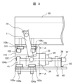
- FIG. FIG. 2 is a front view showing a mechanism of the electric actuator 10 according to the first embodiment in the installed state shown in FIG. 1 .
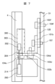
- FIG. 4 is a view taken along the line AA in FIG. 3 .
- FIG. 2 is an exploded view showing the state of the electric operating device when the elevator apparatus is installed.
- FIG. 11 is a configuration diagram of a car and its surroundings of an elevator apparatus according to a second embodiment.
- FIG. 7 is a front view showing a mechanism of an electric actuator 300 according to a second embodiment in the installed state shown in FIG. 6 .
- FIG. 7 is a view taken along the arrow A in FIG. 6 .
- FIG. 13 is a front view showing a mechanism of an electric operating device according to a third embodiment in the installed state shown in FIG.
- FIG. 13 is a rear view showing the mechanism of the electric operating device in the third embodiment in the installed state shown in FIG. 11 is a view taken along the line AA in FIG. 9 and FIG. 10 .
- FIG. 2 is an exploded view showing the state of the electric operating device when the elevator apparatus is installed.
- first bracket refers to components with similar functions, regardless of the reference numerals attached to them.
- FIG. 1 is a diagram showing the configuration of the elevator car and surrounding parts of the elevator device according to the first embodiment of the present invention.
- the elevator system includes a car (1, 50, 51, 52), an emergency stop device 200, and an electric actuator 10 that is mechanically linked to the emergency stop device 200 via a drive mechanism (11-20) and a first lifting rod 21.
- the car chamber 1 (including the floor plate portion, not shown) is supported by a car frame consisting of an upper frame including a crosshead 50, a vertical frame 51 (sling), and a lower frame 52.
- the car is suspended by a main rope (not shown) in a hoistway provided in the building, and slidably engages with a guide rail 4 via a guide device 9.
- a drive device hoist: not shown
- the electric actuator 10 activates the emergency stop device 200 via the drive mechanism (11-20) and the first lifting rod 21.
- the drive mechanism (11-20) is supported by a support provided on the car chamber 1, which in Example 1 is a crosshead 50 that constitutes the upper frame.
- the crosshead 50 is made by combining multiple steel members (channel steel) with a fixed cross-sectional shape (C-shape, U-shape (Japanese katakana), etc.).
- the electric actuator 10 is provided below the drive mechanism (11 to 20). In the first embodiment, the electric actuator 10 is attached to the lower flat surface of the steel material that constitutes the crosshead 50 via a bracket portion shown by the two-dot chain line in FIG. 1.
- the electric operator 10 operates when the descent speed of the car detected by a speed detector (not shown) reaches a predetermined overspeed (for example, a speed not exceeding 1.4 times the rated speed). At this time, the electric operator 10 operates in response to a command signal from a safety control device (not shown) that monitors the speed of the car detected by the speed detector.
- the speed detector and safety control device are provided in the car.
- the operating lever 212 can rotate around a rotation shaft 216, which serves as a fulcrum.
- One end of the first lifting rod 21 ( Figure 1) and one end of a link 217 are connected to one end of the first lifting rod 21 ( Figure 1), and one end of a link 217, respectively.
- One end of a link 219, which has a rotation shaft 218, which serves as a fulcrum, is connected to the other end of the link 217.
- the upper end of a second lifting rod 220 is connected to the other end of the link 219, and the brake 214 is engaged with the lower end of the second lifting rod 220.
- the electric actuator 10 has a feed screw 36 located on the flat surface of the substrate 40 to drive the mover 34.
- the feed screw 36 is rotatably supported by a feed screw support member 41 and a feed screw support member 42 that are fixed on the flat surface of the substrate 40.
- the mover operating section 35 is equipped with a feed nut 39.
- the feed nut 39 is screwed into the feed screw 36.
- the feed screw 36 is rotated by a motor 37.
- the motor 37 is fixedly supported on the flat surface of the substrate 40 by a motor fixing bracket 55.
- the electric operator is attached to the crosshead 50, which constitutes the upper frame of the car, via a first bracket 101, a second bracket 102, and a third bracket 110.
- the first bracket 101 and the third bracket 110 are connected by a bolt 105 and a nut 106.
- the third bracket 110 and the second bracket 102 are connected by a bolt 104b. That is, the first bracket 101 and the second bracket 102 are connected via the third bracket 110.
- the first bracket 101 is connected to the lower flat portion of the crosshead 50 by a bolt 104c that screws into the crosshead 50.
- the longitudinal direction of the long hole 103c is perpendicular to the axial direction of the feed screw 36 and the direction of movement of the movable element 34 within the horizontal plane portion of the first bracket 101.
- the longitudinal direction of the long hole 103c is also perpendicular to the longitudinal direction of the long hole 103a in the base plate portion 40 within the horizontal plane portion of the first bracket 101. Therefore, the first bracket 101 is connected to the crosshead 50 so that its position can be adjusted horizontally and in a direction perpendicular to the direction of movement of the movable element 34.
- the longitudinal direction of the long hole 103b is perpendicular to the axial direction of the feed screw 36 and the moving direction of the movable element 34 in each vertical plane portion of the third bracket 110 and the second bracket 102. Furthermore, the longitudinal direction of the long hole 103b is perpendicular to the longitudinal direction of the long hole 103a in the base plate portion 40 and the long hole 103c in the horizontal plane portion of the first bracket 101 in each vertical plane portion of the first bracket 101 and the third bracket 110. Therefore, the first bracket 101 and the second bracket 102 are connected to each other via the third bracket 110 in a direction perpendicular to the base plate portion 40 so that their positions can be adjusted.
- the mounting positions of the movable member operating unit 35 and the mechanism unit (36, 37, 39-42, 55) of the electric actuator relative to the crosshead 50 are set by the screwing positions of the bolts 104a, 104b, 104c, and can be adjusted in three mutually perpendicular directions by the long holes 103a, 103b, 103c.
- the relative positions of the movable member 34 and the movable member operating unit 35 which are mechanically connected independently to the crosshead 50, can be adjusted in three mutually perpendicular directions. This allows the movable member operating unit 35 of the electric actuator to be positioned so that the movable member 34 is held in an appropriate standby position and returns to a standby state after operation. This improves the reliability of the operation of the electric actuator, and therefore the reliability of the operation of the electric emergency stop device.
- the position adjustment direction set by the long holes 103a, 103b, and 103c can be changed by changing the longitudinal direction of each long hole (the same applies to Example 2 described below).
- the electric actuator of Example 1 is assembled at the manufacturing site before being transported to the installation site, and is then attached to the crosshead 50 using the first to third brackets (101, 102, 110) as shown in Figures 3 and 4.
- the bolt 105 and nut 106 are released from the screwed engagement to separate the first bracket 101 and the third bracket 110.
- the first bracket 101 is held fixed to the crosshead 50 by the bolt 104c.
- the third bracket 110 is held fixed to the second bracket 102 by the bolt 104b.
- the board section 40 to which the movable member operating section 35 and the mechanism section (36, 37, 39-42, 55) are attached, is held fixed to the second bracket 102 by the bolt 104.
- the bolt 105 is passed through a hole in the third bracket 110 and screwed into the nut 106.
- the bolt 105 may be passed through a hole in the first bracket 101 and screwed into the nut 106.
- the bolt 105 and the nut 106 may also be removed from the first bracket 101 and the third bracket 110 and transported to the installation site.
- the bolt 105 only needs to be passed through the hole in the first bracket 101 out of the holes in the first bracket 101 and the third bracket 110, making it easier to assemble the electric actuator at the installation site.
- the movable member 34 is removed from the operating lever 11. However, if damage to the movable member 34 and the operating lever 11 can be reliably prevented during transportation from the manufacturing site to the installation site, the movable member 34 may remain attached to the operating lever 11.
- the first part is the first bracket 101, which is fixed to the crosshead 50 by the bolt 104c.
- the operating lever 11 is rotatably attached to the operating shaft 19, which is fixed to the crosshead 50.
- the second part is the second bracket 102 and the third bracket 110, which are fixed to each other by the bolt 104b.
- the base plate part 40 is fixed to the second bracket 102 by the bolt 104a.
- the third part is the mover 34.
- the safety device 200 and the electric actuator 300 that operates the safety device 200 are disposed at the bottom of the car (1, 50, 51, 52).
- the safety devices 200 are provided on the left and right sides of the bottom of the car.
- the electric actuator 300 is provided above the safety device 200, and on the left and right sides of the bottom of the car.
- the electric actuator 300 is provided on the vertical frame 51 on the car side.
- FIG. 7 shows the mechanism of the electric actuator 300 in the second embodiment, and is a front view in the installed state shown in FIG. 6.
- the pair of wedge-shaped brake elements 214 in the safety device 200 are moved by the electric actuator 300 from a non-braking position to a braking position above the non-braking position. In this braking position, the brake elements 214 are clamped by a pair of guide members 213.
- the electric actuator 300 comprises a mover 302 made of a permanent magnet, and a mover actuator 303 equipped with an electromagnet that operates the mover 302.
- the mover 302 is mechanically linked to a pair of brakes 214 via an operating rod 304 and a connecting member 306.
- One end of the operating rod 304 is rotatably connected to the movable member 302.
- the other end of the operating rod 304 is rotatably connected to one of the pair of brake members 214.
- the movable element 302, the movable element operating part 303, and the operating rod 304 are located on one of the left and right sides of the guide rail 4.
- the movable element 302 is located between the movable element operating part 303 and the guide rail 4.
- the brake element 214 to which the operating rod 304 is connected is located on one of the left and right sides of the guide rail 4 together with the movable element 302, the movable element operating part 303, and the operating rod 304.
- the safety control device determines that the descent speed of the car has reached a predetermined overspeed (for example, a speed not exceeding 1.4 times the rated speed), it outputs a command signal to operate the electric operator 300.
- a predetermined overspeed for example, a speed not exceeding 1.4 times the rated speed
- the control device for the electromagnet part of the mover operating part 303 receives the command signal, it passes a current through the coil of the electromagnet part in the opposite direction to normal.
- the permanent magnet part of the mover 302 receives a repulsive force from the electromagnet part of the mover operating part 303 and moves from the mover operating part 303 towards the guide rail 4. Therefore, the permanent magnet part of the mover 302 is attracted to the guide rail 4 by the magnetic force of the permanent magnet part.
- the brakes 214 are relatively raised from a non-braking position at the bottom of the safety device 200 to a braking position sandwiched between a pair of guide members 213.
- the pair of brakes 214 are pressed between the pair of guide members 213, so they clamp the guide rails 4.
- the car is braked by the frictional force generated between each brake 214 and the guide rails 4.
- the electric operator 300 is attached to the vertical frame 51 (sling) of the car via the first bracket 120, the second bracket 102b, and the third bracket 101b.
- the third bracket 101b and the second bracket 102b are connected by a bolt 104d.
- the first bracket 120 is connected to the side flat portion of the vertical frame 51 by a bolt 104f that screws into the vertical frame 51.
- the vertical plane portion of the first bracket 120 and the side portion of the vertical frame 51 are connected to each other by a bolt 104f.
- the bolt 104f passes through a long hole 103f in the vertical plane portion of the first bracket 120 and is screwed into the side portion of the vertical frame 51.
- the bolt 104f may also pass through a hole in the side portion of the vertical frame 51 and be further screwed into a nut.
- the longitudinal direction of the long hole 103f is perpendicular to the direction of movement of the movable element 302 within the vertical plane of the first bracket 120. Therefore, the first bracket 120 is connected to the side of the vertical frame 51 in a position adjustable manner along a direction perpendicular to the direction of movement of the movable element 302.
- the diameter of the circular hole through which the bolt 107 passes in the first bracket 120 and the third bracket 101b is set so that the positional deviation between the first bracket 120 and the third bracket 101b is within the allowable value, i.e., so that there is practically no positional deviation. Therefore, the third bracket 101b is fixedly abutted against a predetermined position in the first bracket 101 where the hole through which the bolt 107 passes is provided, by tightening the bolt.
- the horizontal plane portion of the third bracket 101b and the horizontal plane portion of the second bracket 102b are connected to each other by a bolt 104d.
- the bolt 104d passes through a long hole 103d in the horizontal plane portion of the second bracket 102b and is screwed into the horizontal plane portion of the third bracket 101b located on the horizontal plane portion of the second bracket 102b.
- the bolt 104d may also pass through a hole in the horizontal plane portion of the third bracket 101b and be further screwed into a nut.
- the longitudinal direction of the long hole 103d is perpendicular to the direction of movement of the movable element 302 in each horizontal plane portion of the third bracket 101b and the second bracket 102b.
- the longitudinal direction of the long hole 103d is also perpendicular to the longitudinal direction of the long hole 103f in the vertical plane portion of the first bracket 120. Therefore, the third bracket 101b and the second bracket 102b are connected to each other so that their positions can be adjusted along the direction perpendicular to the direction of movement of the movable element 302 and along the longitudinal direction of the long hole 103f in each horizontal plane portion of the third bracket 101b and the second bracket 102b.
- the electric actuator 300 which includes a movable element 302 and a movable element operating unit 303 that operates the movable element 302, is placed on the horizontal plane portion of the second bracket 102b and is connected to this horizontal plane portion by a bolt 104e.
- the bolt 104e passes through a long hole 103e in the horizontal plane portion of the second bracket 102b and is screwed into the bottom of the electric actuator 300.
- the bolt 104e may also pass through the bottom of the electric actuator 300 and then be screwed into a nut.
- the longitudinal direction of the long hole 103e is parallel to the direction of movement of the movable element 302. Therefore, the electric actuator 300 and the second bracket 102b are connected to each other so that their positions can be adjusted along the direction of movement of the movable element 34.
- the third bracket 101b allows the mover operating portion 303 of the electric actuator to be accurately positioned relative to the mover 302 when installing the elevator, even in a narrow space.
- the first and second parts described above are brought to the installation site, and the electric actuator is assembled. At this time, the first bracket 120 and the third bracket 101b are connected by the bolt 107.
- FIG. 11 is a view taken along the line AA in FIGS. 9 and 10.
- the emergency stop device is in a non-braked state and the electric actuator is in a standby state.
- the elevator system is in a normal operating state.
- Example 3 The configuration and operation of the electric actuator in Example 3 is the same as that in Example 1 described above.
- the electric operator is attached to the crosshead 50, which constitutes the upper frame of the car, via a first bracket 101, a second bracket 102, and a third bracket 130.
- the first bracket 101 and the second bracket 102 are connected by a bolt 104b.
- the second bracket 102 and the third bracket 130 are connected by a bolt 108.
- the first bracket 101 is connected to the lower flat portion of the crosshead 50 by a bolt 104c that screws into the crosshead 50.
- the base plate 40 on which the movable member operating section 35 that operates the movable member 34 is provided is placed on the horizontal plane of the second bracket 102 and is connected to this plane by a bolt 104a.
- the bolt 104a passes through a long hole 103a in the base plate 40 and is screwed into the second bracket 102.
- the bolt 104a may also pass through a hole in the second bracket 102 and be further screwed into a nut.
- the longitudinal direction of the long hole 103a is parallel to the axial direction of the feed screw 36 and the direction of movement of the movable element 34. Therefore, the base plate 40 and the second bracket 102 are connected to each other so that their positions can be adjusted along the direction of movement of the movable element 34.
- the horizontal plane of the first bracket 101 is connected to the lower plane of the crosshead 50 by a bolt 104c.
- the bolt 104c passes through a long hole 103c in the horizontal plane of the first bracket 101 and is screwed into the lower plane of the crosshead 50.
- the longitudinal direction of the long hole 103c is perpendicular to the axial direction of the feed screw 36 and the direction of movement of the movable element 34 within the horizontal plane portion of the first bracket 101.
- the longitudinal direction of the long hole 103c is also perpendicular to the longitudinal direction of the long hole 103a in the base plate portion 40 within the horizontal plane portion of the first bracket 101. Therefore, the first bracket 101 is connected to the crosshead 50 so that its position can be adjusted horizontally and in a direction perpendicular to the direction of movement of the movable element 34.
- the vertical plane portion of the first bracket 101 and the vertical plane portion of the second bracket 102 are connected to each other by a bolt 104b.
- the bolt 104b passes through a long hole 103b in the vertical plane portion of the second bracket 102 and is screwed into the vertical plane portion of the first bracket 101.
- the bolt 104b may also pass through a hole portion in the first bracket 101 and further be screwed into a nut.
- the longitudinal direction of the long hole 103b is perpendicular to the axial direction of the feed screw 36 and the moving direction of the movable element 34 in each vertical plane portion of the first bracket 101 and the second bracket 102. Furthermore, the longitudinal direction of the long hole 103b is perpendicular to the longitudinal directions of the long hole 103a in the base plate portion 40 and the long hole 103c in the horizontal plane portion of the first bracket 101 in each vertical plane portion of the first bracket 101 and the second bracket 102. Therefore, the first bracket 101 and the second bracket 102 are connected to each other in a manner that allows their positions to be adjusted along the direction perpendicular to the base plate portion 40.
- the mounting positions of the movable member operating unit 35 and the mechanism unit (36, 37, 39-42, 55) of the electric actuator relative to the crosshead 50 are set by the screwing positions of the bolts 104a, 104b, 104c, and can be adjusted in three mutually perpendicular directions by the long holes 103a, 103b, 103c.
- the relative positions of the movable member 34 and the movable member operating unit 35 which are mechanically connected independently to the crosshead 50, can be adjusted in three mutually perpendicular directions. This allows the movable member operating unit 35 of the electric actuator to be positioned so that the movable member 34 is held in an appropriate standby position and returns to a standby state after operation. This improves the reliability of the operation of the electric actuator, and therefore the reliability of the operation of the electric emergency stop device.
- the position adjustment direction set by the long holes 103a, 103b, and 103c can be changed by changing the longitudinal direction of each long hole.
- the third bracket 130 allows the movable member operating part 35 of the electric actuator to be accurately positioned relative to the movable member 34 when installing the elevator, even in a narrow space.
- Figure 12 is an exploded view showing the state of the electric actuator when the elevator system is installed.
- the electric actuator of Example 3 is assembled at the manufacturing site before being transported to the installation site, and is then attached to the crosshead 50 using the first to third brackets (101, 102, 130) as shown in Figures 9 to 11.
- the mounting positions of the movable member operating unit 35 and the mechanism unit (36, 37, 39-42, 55) mounted on the substrate unit 40 relative to the crosshead 50 are adjusted in three mutually perpendicular directions by the long holes 103a, 103b, and 103c through which the bolts 104a, 104b, and 104c pass, respectively.
- the third bracket 130 is fixedly connected to the second bracket 102 by the bolt 108 while abutting against the corner of the first bracket 101.
- the electric actuator of Example 3 is assembled at the manufacturing site, attached to the crosshead 50, and then disassembled into multiple parts (three in FIG. 5) as shown in FIG. 12, using the means described below.
- the bolt 104b is released from the first bracket 101 to separate the first bracket 101 and the second bracket 102. At this time, the first bracket 101 is held fixed to the crosshead 50 by the bolt 104c.
- the third bracket 130 is held fixed to the second bracket 102 by the bolt 108.
- the board section 40 to which the movable member operating section 35 and the mechanism section (36, 37, 39-42, 55) are attached, is held fixed to the second bracket 102 by the bolt 104a.
- the bolt 104b is screwed into the first bracket 101.
- the bolt 104b may be passed through a hole in the first bracket 101 and screwed into a nut.
- the bolt 104b may also be transported to the installation site in a state where it is removed from the first bracket 101 and the second bracket 102.
- the movable member 34 is removed from the operating lever 11. However, if damage to the movable member 34 and the operating lever 11 can be reliably prevented during transportation from the manufacturing site to the installation site, the movable member 34 may remain attached to the operating lever 11.
- the electric actuator is disassembled into the following first to third parts, as shown in Figure 12.
- the first part is the first bracket 101, which is fixed to the crosshead 50 by the bolt 104c.
- the operating lever 11 is rotatably attached to the operating shaft 19, which is fixed to the crosshead 50.
- the second part is the second bracket 102 and the third bracket 130, which are fixed to each other by the bolt 108.
- the base plate part 40 is fixed to the second bracket 102 by the bolt 104a.
- the third part is the mover 34.
- the first to third parts described above are brought to the installation site, and the electric actuator is assembled. At this time, the movable member 34 is attached to the operating lever 11, and the first bracket 101 in the first part is connected to the second bracket 102 in the second part by the bolt 104b while the corner of the first bracket 101 is abutted against the third bracket 130.
- the first bracket 101 and the second bracket 102 are aligned with each other by the shoulder rest of the third bracket 130.
- the state when assembled at the manufacturing site is reproduced, that is, the state in which the mover operating part 35 is positioned relative to the mover 34 attached to the crosshead 50.
- the present invention is not limited to the above-mentioned Examples 1 to 3, but includes various modified examples.
- the above-mentioned Examples 1 to 3 have been described in detail to clearly explain the present invention, and the present invention is not necessarily limited to having all of the configurations described.
- the drive mechanism (11-20) and electric actuator 10 of the safety device in Examples 1 and 3 may be provided on the lower or side of the car, in addition to the upper part.
- the drive mechanism and electric actuator are provided on the structural members of the car as appropriate.
- the drive mechanism (11-20) and electric actuator 10 are installed below the crosshead 50. This allows the drive mechanism (11-20) and electric actuator 10 to be provided on the car without increasing the overhead dimensions.
- the elevator system may have a machine room in which the hoist and control panel are installed, or it may be a so-called machine room-less elevator.
Landscapes
- Engineering & Computer Science (AREA)
- Mechanical Engineering (AREA)
- Maintenance And Inspection Apparatuses For Elevators (AREA)
Priority Applications (3)
| Application Number | Priority Date | Filing Date | Title |
|---|---|---|---|
| PCT/JP2023/022646 WO2024261827A1 (ja) | 2023-06-19 | 2023-06-19 | エレベータ装置の据付方法、並びにエレベータ装置 |
| CN202380098545.8A CN121175255A (zh) | 2023-06-19 | 2023-06-19 | 电梯装置的安装方法以及电梯装置 |
| JP2025527236A JPWO2024261827A1 (https=) | 2023-06-19 | 2023-06-19 |
Applications Claiming Priority (1)
| Application Number | Priority Date | Filing Date | Title |
|---|---|---|---|
| PCT/JP2023/022646 WO2024261827A1 (ja) | 2023-06-19 | 2023-06-19 | エレベータ装置の据付方法、並びにエレベータ装置 |
Publications (1)
| Publication Number | Publication Date |
|---|---|
| WO2024261827A1 true WO2024261827A1 (ja) | 2024-12-26 |
Family
ID=93935177
Family Applications (1)
| Application Number | Title | Priority Date | Filing Date |
|---|---|---|---|
| PCT/JP2023/022646 Ceased WO2024261827A1 (ja) | 2023-06-19 | 2023-06-19 | エレベータ装置の据付方法、並びにエレベータ装置 |
Country Status (3)
| Country | Link |
|---|---|
| JP (1) | JPWO2024261827A1 (https=) |
| CN (1) | CN121175255A (https=) |
| WO (1) | WO2024261827A1 (https=) |
Citations (6)
| Publication number | Priority date | Publication date | Assignee | Title |
|---|---|---|---|---|
| US20200198932A1 (en) * | 2018-12-20 | 2020-06-25 | Kone Corporation | Elevator safety gear trigger and reset system |
| CN213864909U (zh) * | 2020-10-22 | 2021-08-03 | 苏州博量电梯科技有限公司 | 一种电子安全钳制动块位移检测装置 |
| JP2021130550A (ja) * | 2020-02-20 | 2021-09-09 | 株式会社日立製作所 | 非常止め装置及びエレベーター |
| JP2022072312A (ja) * | 2020-10-29 | 2022-05-17 | 株式会社日立製作所 | 非常止め装置及びエレベーター |
| JP2022114059A (ja) * | 2021-01-26 | 2022-08-05 | 株式会社日立製作所 | エレベータ装置 |
| WO2022224351A1 (ja) * | 2021-04-20 | 2022-10-27 | 株式会社日立製作所 | エレベータ装置 |
-
2023
- 2023-06-19 WO PCT/JP2023/022646 patent/WO2024261827A1/ja not_active Ceased
- 2023-06-19 JP JP2025527236A patent/JPWO2024261827A1/ja active Pending
- 2023-06-19 CN CN202380098545.8A patent/CN121175255A/zh active Pending
Patent Citations (6)
| Publication number | Priority date | Publication date | Assignee | Title |
|---|---|---|---|---|
| US20200198932A1 (en) * | 2018-12-20 | 2020-06-25 | Kone Corporation | Elevator safety gear trigger and reset system |
| JP2021130550A (ja) * | 2020-02-20 | 2021-09-09 | 株式会社日立製作所 | 非常止め装置及びエレベーター |
| CN213864909U (zh) * | 2020-10-22 | 2021-08-03 | 苏州博量电梯科技有限公司 | 一种电子安全钳制动块位移检测装置 |
| JP2022072312A (ja) * | 2020-10-29 | 2022-05-17 | 株式会社日立製作所 | 非常止め装置及びエレベーター |
| JP2022114059A (ja) * | 2021-01-26 | 2022-08-05 | 株式会社日立製作所 | エレベータ装置 |
| WO2022224351A1 (ja) * | 2021-04-20 | 2022-10-27 | 株式会社日立製作所 | エレベータ装置 |
Also Published As
| Publication number | Publication date |
|---|---|
| JPWO2024261827A1 (https=) | 2024-12-26 |
| CN121175255A (zh) | 2025-12-19 |
Similar Documents
| Publication | Publication Date | Title |
|---|---|---|
| JP4709650B2 (ja) | エレベータ用の遠隔リセット可能なロープ無し非常停止装置 | |
| JP5350263B2 (ja) | エレベータ制動装置 | |
| JP7470651B2 (ja) | エレベータ装置 | |
| JP7292230B2 (ja) | 非常止め装置及びエレベーター | |
| JP2008511521A (ja) | エレベータシステムで使用する安全装置 | |
| JP7524487B2 (ja) | 非常止め装置用電動作動器の故障検出装置および故障検出方法 | |
| JP7522325B2 (ja) | エレベータ装置 | |
| JP7554945B2 (ja) | 非常止め装置用電動作動器の動作確認装置および動作確認方法 | |
| WO2024261827A1 (ja) | エレベータ装置の据付方法、並びにエレベータ装置 | |
| JP7407936B2 (ja) | エレベータ装置 | |
| WO2024157390A1 (ja) | エレベータ装置 | |
| JP7505119B2 (ja) | エレベータ装置 | |
| JP7588657B2 (ja) | エレベータ装置 | |
| WO2022172364A1 (ja) | エレベータ装置 | |
| US20230139867A1 (en) | Frictionless electronic safety actuator | |
| JP7556160B2 (ja) | エレベータ装置 | |
| JP7562006B2 (ja) | エレベータ装置 | |
| JP2023030908A (ja) | エレベータ装置 | |
| US20250353703A1 (en) | Elevator | |
| WO2022013939A1 (ja) | エレベータ装置 | |
| WO2025191701A1 (ja) | エレベータ装置 | |
| WO2022201529A1 (ja) | エレベータ装置 | |
| WO2025191633A1 (ja) | エレベータ装置、並びにエレベータ装置の保守方法 | |
| WO2022162874A1 (ja) | エレベータ装置 | |
| JP6408959B2 (ja) | エレベーター |
Legal Events
| Date | Code | Title | Description |
|---|---|---|---|
| 121 | Ep: the epo has been informed by wipo that ep was designated in this application |
Ref document number: 23942265 Country of ref document: EP Kind code of ref document: A1 |
|
| ENP | Entry into the national phase |
Ref document number: 2025527236 Country of ref document: JP Kind code of ref document: A |
|
| NENP | Non-entry into the national phase |
Ref country code: DE |