WO2024257701A1 - 圧縮機用エンクロージャ及び圧縮機ユニット - Google Patents
圧縮機用エンクロージャ及び圧縮機ユニット Download PDFInfo
- Publication number
- WO2024257701A1 WO2024257701A1 PCT/JP2024/020857 JP2024020857W WO2024257701A1 WO 2024257701 A1 WO2024257701 A1 WO 2024257701A1 JP 2024020857 W JP2024020857 W JP 2024020857W WO 2024257701 A1 WO2024257701 A1 WO 2024257701A1
- Authority
- WO
- WIPO (PCT)
- Prior art keywords
- cover
- compressor
- enclosure
- sound
- connection part
- Prior art date
- Legal status (The legal status is an assumption and is not a legal conclusion. Google has not performed a legal analysis and makes no representation as to the accuracy of the status listed.)
- Ceased
Links
Images



Classifications
-
- F—MECHANICAL ENGINEERING; LIGHTING; HEATING; WEAPONS; BLASTING
- F04—POSITIVE - DISPLACEMENT MACHINES FOR LIQUIDS; PUMPS FOR LIQUIDS OR ELASTIC FLUIDS
- F04C—ROTARY-PISTON, OR OSCILLATING-PISTON, POSITIVE-DISPLACEMENT MACHINES FOR LIQUIDS; ROTARY-PISTON, OR OSCILLATING-PISTON, POSITIVE-DISPLACEMENT PUMPS
- F04C23/00—Combinations of two or more pumps, each being of rotary-piston or oscillating-piston type, specially adapted for elastic fluids; Pumping installations specially adapted for elastic fluids; Multi-stage pumps specially adapted for elastic fluids
- F04C23/008—Hermetic pumps
-
- F—MECHANICAL ENGINEERING; LIGHTING; HEATING; WEAPONS; BLASTING
- F04—POSITIVE - DISPLACEMENT MACHINES FOR LIQUIDS; PUMPS FOR LIQUIDS OR ELASTIC FLUIDS
- F04B—POSITIVE-DISPLACEMENT MACHINES FOR LIQUIDS; PUMPS
- F04B35/00—Piston pumps specially adapted for elastic fluids and characterised by the driving means to their working members, or by combination with, or adaptation to, specific driving engines or motors, not otherwise provided for
- F04B35/04—Piston pumps specially adapted for elastic fluids and characterised by the driving means to their working members, or by combination with, or adaptation to, specific driving engines or motors, not otherwise provided for the means being electric
-
- F—MECHANICAL ENGINEERING; LIGHTING; HEATING; WEAPONS; BLASTING
- F04—POSITIVE - DISPLACEMENT MACHINES FOR LIQUIDS; PUMPS FOR LIQUIDS OR ELASTIC FLUIDS
- F04B—POSITIVE-DISPLACEMENT MACHINES FOR LIQUIDS; PUMPS
- F04B39/00—Component parts, details, or accessories, of pumps or pumping systems specially adapted for elastic fluids, not otherwise provided for in, or of interest apart from, groups F04B25/00 - F04B37/00
- F04B39/12—Casings; Cylinders; Cylinder heads; Fluid connections
- F04B39/121—Casings
-
- F—MECHANICAL ENGINEERING; LIGHTING; HEATING; WEAPONS; BLASTING
- F04—POSITIVE - DISPLACEMENT MACHINES FOR LIQUIDS; PUMPS FOR LIQUIDS OR ELASTIC FLUIDS
- F04C—ROTARY-PISTON, OR OSCILLATING-PISTON, POSITIVE-DISPLACEMENT MACHINES FOR LIQUIDS; ROTARY-PISTON, OR OSCILLATING-PISTON, POSITIVE-DISPLACEMENT PUMPS
- F04C18/00—Rotary-piston pumps specially adapted for elastic fluids
- F04C18/02—Rotary-piston pumps specially adapted for elastic fluids of arcuate-engagement type, i.e. with circular translatory movement of co-operating members, each member having the same number of teeth or tooth-equivalents
- F04C18/0207—Rotary-piston pumps specially adapted for elastic fluids of arcuate-engagement type, i.e. with circular translatory movement of co-operating members, each member having the same number of teeth or tooth-equivalents both members having co-operating elements in spiral form
- F04C18/0215—Rotary-piston pumps specially adapted for elastic fluids of arcuate-engagement type, i.e. with circular translatory movement of co-operating members, each member having the same number of teeth or tooth-equivalents both members having co-operating elements in spiral form where only one member is moving
-
- F—MECHANICAL ENGINEERING; LIGHTING; HEATING; WEAPONS; BLASTING
- F04—POSITIVE - DISPLACEMENT MACHINES FOR LIQUIDS; PUMPS FOR LIQUIDS OR ELASTIC FLUIDS
- F04C—ROTARY-PISTON, OR OSCILLATING-PISTON, POSITIVE-DISPLACEMENT MACHINES FOR LIQUIDS; ROTARY-PISTON, OR OSCILLATING-PISTON, POSITIVE-DISPLACEMENT PUMPS
- F04C29/00—Component parts, details or accessories of pumps or pumping installations, not provided for in groups F04C18/00 - F04C28/00
- F04C29/06—Silencing
-
- F—MECHANICAL ENGINEERING; LIGHTING; HEATING; WEAPONS; BLASTING
- F04—POSITIVE - DISPLACEMENT MACHINES FOR LIQUIDS; PUMPS FOR LIQUIDS OR ELASTIC FLUIDS
- F04C—ROTARY-PISTON, OR OSCILLATING-PISTON, POSITIVE-DISPLACEMENT MACHINES FOR LIQUIDS; ROTARY-PISTON, OR OSCILLATING-PISTON, POSITIVE-DISPLACEMENT PUMPS
- F04C29/00—Component parts, details or accessories of pumps or pumping installations, not provided for in groups F04C18/00 - F04C28/00
- F04C29/06—Silencing
- F04C29/063—Sound absorbing materials
-
- F—MECHANICAL ENGINEERING; LIGHTING; HEATING; WEAPONS; BLASTING
- F04—POSITIVE - DISPLACEMENT MACHINES FOR LIQUIDS; PUMPS FOR LIQUIDS OR ELASTIC FLUIDS
- F04C—ROTARY-PISTON, OR OSCILLATING-PISTON, POSITIVE-DISPLACEMENT MACHINES FOR LIQUIDS; ROTARY-PISTON, OR OSCILLATING-PISTON, POSITIVE-DISPLACEMENT PUMPS
- F04C29/00—Component parts, details or accessories of pumps or pumping installations, not provided for in groups F04C18/00 - F04C28/00
- F04C29/06—Silencing
- F04C29/065—Noise dampening volumes, e.g. muffler chambers
- F04C29/066—Noise dampening volumes, e.g. muffler chambers with means to enclose the source of noise
-
- F—MECHANICAL ENGINEERING; LIGHTING; HEATING; WEAPONS; BLASTING
- F04—POSITIVE - DISPLACEMENT MACHINES FOR LIQUIDS; PUMPS FOR LIQUIDS OR ELASTIC FLUIDS
- F04C—ROTARY-PISTON, OR OSCILLATING-PISTON, POSITIVE-DISPLACEMENT MACHINES FOR LIQUIDS; ROTARY-PISTON, OR OSCILLATING-PISTON, POSITIVE-DISPLACEMENT PUMPS
- F04C2240/00—Components
- F04C2240/30—Casings or housings
-
- F—MECHANICAL ENGINEERING; LIGHTING; HEATING; WEAPONS; BLASTING
- F04—POSITIVE - DISPLACEMENT MACHINES FOR LIQUIDS; PUMPS FOR LIQUIDS OR ELASTIC FLUIDS
- F04C—ROTARY-PISTON, OR OSCILLATING-PISTON, POSITIVE-DISPLACEMENT MACHINES FOR LIQUIDS; ROTARY-PISTON, OR OSCILLATING-PISTON, POSITIVE-DISPLACEMENT PUMPS
- F04C2270/00—Control; Monitoring or safety arrangements
- F04C2270/12—Vibration
Definitions
- This disclosure relates to a compressor enclosure that houses a compressor and a compressor unit.
- Electric compressors are used as compressors in the refrigeration cycles of air conditioning in electric and hybrid vehicles. Electric compressors are configured so that a compression section equipped with a scroll mechanism etc. is driven by an electric motor. Electric compressors operate in response to air conditioning demands even when the vehicle is stopped, so further noise reduction is required.
- the soundproof cover in Patent Document 1 includes a cover portion that is a sound-absorbing material that covers the compressor, and a soundproofing member that covers the cover portion.
- Patent Document 1 describes arranging a sound-proofing material to cover the outer surface of the cover portion, which is made of sound-absorbing material, there is no specific description of the contact state between the cover portion and the sound-proofing material. In addition, there is no specific description of the contact state between the compressor and the cover portion.
- the inventors discovered that the noise generated by the compressor can be effectively reduced by adjusting the contact state between the compressor and the first cover (sound-absorbing material) and second cover (sound-proofing material).
- This disclosure has been made in consideration of these circumstances, and aims to provide a compressor enclosure and compressor unit that can reduce the noise generated by the compressor depending on the contact state between the compressor and the first and second covers.
- a compressor enclosure includes a first cover that houses and surrounds a compressor, a plurality of first connection parts that connect the first cover to the compressor while forming a space between the first cover and the compressor, and a second cover that houses and surrounds the first cover and has a higher density than the first cover.
- the compressor unit includes the compressor enclosure described above and the compressor housed within the compressor enclosure.
- the noise generated by the compressor can be reduced by adjusting the contact state between the compressor and the first and second covers.
- FIG. 1 is a perspective view showing a compressor enclosure according to a first embodiment of the present disclosure.
- FIG. 1 is a perspective view showing a compressor according to a first embodiment of the present disclosure.
- FIG. 2 is a vertical cross-sectional view showing an enclosure housing a compressor according to the first embodiment of the present disclosure.
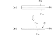
- 10A to 10C are schematic diagrams showing a process of producing a first cover by removing a skin layer.
- FIG. 11 is a vertical cross-sectional view showing an enclosure housing a compressor according to a second embodiment of the present disclosure.
- FIG. 1 shows an enclosure (compressor enclosure) 1 that entirely covers a compressor 2.
- a main body 10 of the enclosure 1 has a shape corresponding to the outer shape of the compressor 2, and is divided at a dividing plane P into two divided bodies 10A and 10B on the left and right.
- the dividing plane P extends vertically when the mounting legs 3 of the compressor 2 are positioned downward.
- the mounting legs 3 of the compressor 2 are fixing parts for mounting the compressor to a fixing part on the vehicle side.
- the main body 10 of the enclosure 1 has a double structure consisting of a first cover 21 and a second cover 22, which will be described later using Figure 3.
- the left and right divided bodies 10A and 10B shown in FIG. 1 can be fixed to each other using various fixing methods, such as engagement using bolts and nuts, claws, etc.
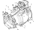
- FIG. 2 shows the compressor 2 with the enclosure 1 shown in FIG. 1 removed.
- the compressor 2 shown in the figure does not have an exact shape to the enclosure 1 shown in FIG. 1, for example in terms of the number of mounting legs 3, but there is no significant difference in terms of the description of the compressor that is soundproofed by the enclosure 1.
- the enclosure 1 of this embodiment can be widely applied to compressors with the structure described below.
- the compressor 2 constitutes part of the refrigeration cycle used in vehicle air conditioning, sucking in the refrigerant guided from the evaporator, compressing it, and discharging the compressed refrigerant to the condenser.
- the compressor 2 has a generally cylindrical shape with its longitudinal axis in the horizontal direction.
- the compressor 2 is an electric compressor, and includes a compression section 2A having a scroll mechanism, and a motor section (electric motor section) 2B equipped with an electric motor that drives the scroll mechanism.
- the compression section 2A is located at the front side of the compressor 2 (left side in FIG. 2) and has a fixed scroll and an orbiting scroll inside. Since the orbiting scroll orbits while partially contacting the fixed scroll, the compression section 2A is the main source of vibration and noise for the compressor 2.
- a cylindrical discharge port (extension) 5 for discharging the compressed refrigerant is provided at the top of the compression section 2A.
- the motor section 2B is connected to the rear of the compression section 2A and is located on the rear side of the compressor 2 (on the right side in FIG. 2).
- the motor section 2B includes an electric motor having a stator and a rotor, and an inverter section that supplies power to the electric motor.
- the diameter of the motor section 2B is larger than the diameter of the compression section 2A.
- a cylindrical suction port 7 is provided at the top of the motor section 2B to draw the refrigerant into the compressor 2.
- a cylindrical wiring guide tube (extension) 9 is provided at the top of the motor section 2B near the suction port (extension) 7 to guide harnesses such as power cables and signal lines to the outside of the compressor 2.
- FIG. 3 shows a vertical cross section of the compressor 2 in FIG. 2 with the enclosure 1 attached. Note that the compressor 2 in FIG. 3 is reversed from the compressor 2 shown in FIG. 2, with the compression section 2A on the right and the motor section 2B on the left. In other words, FIG. 3 is a vertical cross section seen from the rear side of FIG. 2.
- the main body 10 of the enclosure 1 has a double structure including a first cover 21 and a second cover 22.
- the first cover 21 houses and surrounds the entire compressor 2.
- the first cover 21 is rigid enough to bend under its own weight, and is made of a foamed resin material such as urethane foam (soft PUR foam). Therefore, the first cover 21 is softer and has a lower density (lower specific gravity and higher foaming rate) than rigid plastic materials such as PP (polypropylene) and PBT (polybutylene terephthalate).
- a gap of, for example, 5 mm to 20 mm is provided between the first cover 21 and the compressor 2, and the first cover 21 is in contact with the compressor 2 at multiple points via the first connection part 11.
- the first connection part 11 has a protruding shape that protrudes from the inner surface of the first cover 21, and the tip of the first connection part 11 is in contact with the outer surface of the compressor 2.
- the first connection part 11 is preferably made of a material softer than the material of the first cover 21, and may be, for example, a rubber sponge such as an EPDM (ethylene propylene diene rubber) foam material such as Eptsealer (registered trademark), open-cell polyethylene, or the like.
- the first connection part 11 is preferably fixed to the inner surface of the first cover 21 by adhesion or the like.
- the first connection parts 11 are mainly provided on the motor section 2B of the compressor 2. More specifically, they are provided on the front end A1, rear end A2, and intermediate section A3 of the motor section 2B. The first connection parts 11 on the intermediate section A3 can be omitted as appropriate.
- the first connection parts 11 are provided at multiple locations in the circumferential direction of the compressor 2. For example, as shown by arrow C in FIG. 2, they are provided on both the lower and upper sides of the compressor 2. As in this embodiment, it is preferable to provide more first connection parts 11 on the motor section 2B than on the compression section 2A.
- a hole is formed in the main body 10 at a position corresponding to the discharge port 5 so that the discharge port 5 can be inserted therethrough.
- a sealant 14 is provided as the first connection part 11 as shown in FIG. 3. The sealant 14 is arranged so as to wrap around the outer periphery of the cylindrical part of the discharge port 5.
- the second cover 22 encloses the entire first cover 21 inside.
- the second cover 22 has a higher density than the first cover 21 (higher specific gravity and lower air bubble rate) and is rigid enough to maintain its shape under its own weight.
- the material used for the first cover 21 is a hard resin material that does not foam or foams only to a small extent.
- the second cover 22 can be made of a rigid plastic material such as PP (polypropylene) or PBT (polybutylene terephthalate).
- the second connection parts 12 are protruding from the inner surface of the second cover 22, and the tip of the second connection parts 12 contacts the outer surface of the first cover 21.
- the second connection part 12 can be a resin integrated with the second cover 22.
- the tip of the second connection part 12 is connected to the outer surface of the first cover 21.
- the outer surface of the first cover 21 is a foamed surface 21c in which the skin layer 21a has been removed and numerous recesses are exposed, as shown in FIG. 4(a).
- foamed resin is molded in a mold at a high temperature of 60°C or higher using polyurethane or the like as a raw material, as shown in FIG. 4(a), a core layer 21b that becomes a foamed layer and skin layers 21a that become solid layers are formed on the front and back sides of the core layer 21b.
- a foamed surface 21c in which numerous recesses caused by foaming are exposed appears on the surface of the first cover 21, as shown in FIG. 4(b). Then, by resin-molding the second cover 22 onto the first cover 21, the resin of the second connection part 12 fills the numerous recesses in the foam surface 21c of the first cover 21, and the tip of the second connection part 12 can be mechanically and/or chemically bonded to the outer surface of the first cover 21.
- the second connection part 12 may be made of, for example, a rubber sponge such as an EPDM (ethylene propylene diene rubber) foam material such as EPTSEALER (registered trademark), open-cell polyethylene, or the like.
- EPDM ethylene propylene diene rubber
- EPTSEALER registered trademark
- open-cell polyethylene or the like.
- the second connection part 12 is provided at a different position from the first connection part 11 when the first connection part 11 is viewed from the second cover 22. In other words, the second connection part 12 does not overlap the area in which the first connection part 11 exists. This prevents the first connection part 11, the first cover 21, the second connection part 12, and the second cover 22 from being continuously present in the thickness direction of the main body part 10.
- the effects of the present embodiment described above are as follows. Since the plurality of first connection parts 11 can form a space between the compressor 2 and the inner surface of the first cover 21, noise generated by the compressor 2 can be effectively suppressed.
- the second cover 22 is provided to house the first cover 21. As a result, when sound generated by the compressor 2 propagates through the first cover 21, it is converted into thermal energy and attenuated. Then, the sound is reflected to the inside by the second cover 22, which has a higher density than the first cover 21. The reflected sound is further attenuated by the first cover 21. As a result, the first cover 21, which has a low density, and the second cover 22, which has a high density, can reduce the propagation of the sound of the compressor 2 to the outside of the enclosure 1.
- the second connection part 12 When the first connection part 11 is viewed from the second cover 22, the second connection part 12 is provided at a position different from the first connection part 11, so that it is possible to prevent sound (vibration) from the compressor 2 from being transmitted directly to the second cover 22 through the first connection part 11, the first cover 21 and the second connection part 12 in a solid state. Since the solid-borne sound propagating from the first connection portion 11 to the first cover 21 passes through the first cover 21 on the way to the second cover 22, the sound (vibration) can be absorbed and attenuated. In addition, since the second cover 22 is connected to the first cover 21 by the second connection portion 12, the first cover 21 can absorb and attenuate the vibration of the second cover 22.
- the second connection part 12 is mechanically and/or chemically bonded to the numerous depressions that appear on the surface of the foamed side of the first cover 21, improving the reliability of the bond and preventing the bond from peeling off and causing contact noise between the first cover 21 and the second connection part 12.
- a second embodiment of the present disclosure will be described with reference to Fig. 5.
- a space is formed between the first cover 21 and the second cover 22 by providing the second connection portion 12, but in this embodiment, no space is formed between the first cover 21 and the second cover 22.
- Other configurations of the second embodiment are similar to those of the first embodiment, so the same reference numerals are used and the description thereof will be omitted.
- the second connection portion 12 (see FIG. 3) of the first embodiment is not provided between the first cover 21 and the second cover 22, and the outer surface of the first cover 21 and the inner surface of the second cover 22 are in contact with each other.
- the first cover 21 and the second cover 22 may be joined together to form an integrated unit, or may simply be stacked on top of each other without being joined.
- the effects of the present embodiment described above are as follows.
- the first cover 21 and the second cover 22 are in contact with each other so as not to form a space between the first cover 21 and the second cover 22. This allows the first cover 21 to efficiently absorb and damp vibrations of the second cover 22.
- the multiple first connection parts 11 can form a space between the compressor 2 and the inner surface of the first cover 21, so that noise generated by the compressor 2 can be effectively suppressed.
- the second cover 22 is provided to house the first cover 21.
- the sound generated by the compressor 2 propagates through the first cover 21, it is converted into thermal energy and attenuated.
- the sound is then reflected to the inside by the second cover 22, which has a higher density than the first cover 21.
- the reflected sound is further attenuated by the first cover 21.
- the low-density first cover 21 and the high-density second cover 22 can reduce the propagation of the sound of the compressor 2 to the outside of the enclosure 1.
- the skin layer 21a may be removed to create a large number of dents on the surface of the foamed side of the first cover 21. This allows the second cover 22 to be mechanically and/or chemically bonded, improving the reliability of the bond and preventing the bond from peeling off and causing contact noise between the first cover 21 and the second cover 22.
- the first cover 21 and the second cover 22 are described on the assumption that they are made of a foamed resin material, but other porous resin materials may be used.
- a porous resin material may be used in which nitrogen or carbon dioxide is blown in during kneading of the resin material without using a foaming agent, making the resin porous.
- nitrogen or carbon dioxide is not blown in during kneading of the resin.
- the compressor enclosure (1) includes a first cover (21) that houses and surrounds a compressor (2), a plurality of first connection parts (11) that connect the first cover and the compressor while forming a space between the first cover and the compressor, and a second cover (22) that houses and surrounds the first cover and has a higher density than the first cover.
- the second cover is provided to house the first cover.
- the second cover is provided to house the first cover.
- the first cover when sound generated by the compressor propagates through the first cover, it is converted to thermal energy and attenuated. Then, the sound is reflected to the inside by the second cover, which has a higher density than the first cover. The reflected sound is further attenuated by the first cover.
- the low-density first cover and the high-density second cover can reduce the propagation of the compressor sound to the outside of the enclosure.
- the material of the first cover has a rigidity sufficient to bend under its own weight, and may be, for example, a foamed resin material (such as soft PUR foam) made by foaming polyurethane, polyisocyanurate, or the like.
- the material for the second cover is, for example, rigid enough to maintain its shape without bending under its own weight, and may be, for example, a plastic material such as PP (polypropylene) or PBT (polybutylene terephthalate), or a hard resin material that does not foam or foams only to a small extent like the material used for the first cover.
- the first connection part and the second connection part need only connect two opposing members when the enclosure is attached to the compressor, and may be fixed to the opposing members by integral molding, adhesive bonding, etc., or may be fixed by being pressed down with a compressive force in a removable manner without using adhesive, etc.
- the compressor enclosure according to the second aspect of the present disclosure includes, in the first aspect, a plurality of second connection parts (12) that connect the first cover and the second cover while forming a space between the first cover and the second cover.
- the second connection parts form a space between the first cover and the second cover, so that the propagation of vibration from the first cover to the second cover can be reduced. Also, the reflection and attenuation of sound waves at the boundary between the second connection parts and the first cover can reduce the radiation of sound to the outside from the second cover. In addition, by forming a space between the first cover and the second cover using the second connection part, it is possible to prevent the first cover from vibrating due to vibrations of a vehicle body equipped with a compressor, etc., and coming into contact with the second cover and generating noise.
- the second connection portion is provided at a different position from the first connection portion when the first connection portion is viewed from the second cover.
- the second connection part is provided at a position different from the first connection part when viewed from the second cover, it is possible to prevent sound (vibration) from the compressor from being transmitted directly to the second cover through the first connection part, the first cover, and the second connection part. Since the solid-borne sound propagating from the first connection part to the first cover passes through the first cover on its way to the second cover, the sound (vibration) can be absorbed and attenuated. In addition, since the second cover is connected to the first cover by the second connection part, the first cover can absorb and attenuate the vibration of the second cover.
- the first cover is made of a foam
- the second connection portion is coupled to the foam surface (21c) of the first cover.
- the second connection part is mechanically and/or chemically bonded to the numerous depressions that appear on the surface of the foamed side of the first cover, improving the reliability of the bond and preventing the bond from peeling off and causing contact noise between the first cover and the second connection part.
- the first cover and the second cover are in contact with each other so that no space is formed between them.
- first cover and the second cover are in contact with each other so that no space is formed between them, which allows the first cover to efficiently absorb and damp vibrations of the second cover.
- "so as not to form a space” means that substantially no space is formed; for example, the space that inevitably occurs when the first cover and the second cover are brought into contact entirely is acceptable.
- the compressor enclosure according to the sixth aspect of the present disclosure is the fifth aspect, in which the first cover is made of foam and the second cover is bonded to the foam surface of the first cover.
- the second cover is mechanically and/or chemically bonded to the numerous depressions that appear on the surface of the foamed side of the first cover, improving the reliability of the bond and preventing the bond from peeling off and causing contact noise between the first cover and the second cover.
- the compressor enclosure according to the seventh aspect of the present disclosure is the fourth or sixth aspect, in which the foamed surface is formed by removing the surface of the first cover.
- the compressor unit according to the first aspect of the present disclosure includes a compressor enclosure according to any of the aspects described above, and the compressor housed within the compressor enclosure.
Landscapes
- Engineering & Computer Science (AREA)
- Mechanical Engineering (AREA)
- General Engineering & Computer Science (AREA)
- Compressor (AREA)
- Applications Or Details Of Rotary Compressors (AREA)
Abstract
圧縮機と第1カバーと第2カバーとの間の接触状態によって圧縮機から発生する騒音を低減できる圧縮機用エンクロージャを提供する。圧縮機用エンクロージャ(1)は、圧縮機(2)を内部に収容して包囲する第1カバー(21)と、第1カバー(21)と圧縮機(2)との間に空間を形成した状態で第1カバー(21)と圧縮機(2)とを接続する複数の第1接続部(11)と、第1カバー(21)を内部に収容して包囲するとともに、第1カバー(21)よりも密度が大きい第2カバー(22)と、を備えている。
Description
本開示は、圧縮機を内部に収容する圧縮機用エンクロージャ及び圧縮機ユニットに関するものである。
電気自動車やハイブリッド自動車の空調用冷凍サイクルに用いられる圧縮機として、電動圧縮機が用いられる。電動圧縮機は、スクロール機構等を備えた圧縮部を電動モータによって駆動する構成となっている。電動圧縮機は、車両の停止時にも空調の要求に応じて動作するので、さらなる騒音の低減が求められる。
圧縮機の騒音低減のためには、騒音源の音圧レベルを低減する方法と、発生する騒音を吸音・遮音する方法がある。後者の吸音・遮音する手段として、圧縮機に対して防音カバーを設ける構造が種々提案されている。例えば、特許文献1の防音カバーは、圧縮機を覆う吸音材であるカバー部と、カバー部を覆う遮音部材とを備えている。
しかし、特許文献1には、吸音材であるカバー部の外面を覆うように遮音部材を配置することが記載されているが、カバー部と遮音部材との間の接触状態に関しては具体的な記載がない。また、圧縮機とカバー部との間の接触状態に関しての具体的な記載はない。
本発明者等は、鋭意検討した結果、圧縮機と第1カバー(吸音部材)と第2カバー(遮音部材)との間の接触状態によって圧縮機から発生する騒音を有効に低減できることを見出した。
本開示は、このような事情に鑑みてなされたものであって、圧縮機と第1カバーと第2カバーとの間の接触状態によって圧縮機から発生する騒音を低減できる圧縮機用エンクロージャ及び圧縮機ユニットを提供することを目的とする。
本開示の一態様に係る圧縮機用エンクロージャは、圧縮機を内部に収容して包囲する第1カバーと、前記第1カバーと前記圧縮機との間に空間を形成した状態で該第1カバーと該圧縮機とを接続する複数の第1接続部と、前記第1カバーを内部に収容して包囲するとともに、前記第1カバーよりも密度が大きい第2カバーと、を備えている。
本開示の一態様に係る圧縮機ユニットは、上記の圧縮機用エンクロージャと、前記圧縮機用エンクロージャ内に収容された前記圧縮機と、を備えている。
圧縮機と第1カバーと第2カバーとの間の接触状態によって圧縮機から発生する騒音を低減できる。
[第1実施形態]
以下に、本開示に係る第1実施形態について、図面を参照して説明する。
図1には、圧縮機2の全体を覆うエンクロージャ(圧縮機用エンクロージャ)1が示されている。エンクロージャ1の本体部10は、圧縮機2の外形に対応した形状とされており、分割面Pにて左右に2つの分割体10A,10Bに分割されている。
以下に、本開示に係る第1実施形態について、図面を参照して説明する。
図1には、圧縮機2の全体を覆うエンクロージャ(圧縮機用エンクロージャ)1が示されている。エンクロージャ1の本体部10は、圧縮機2の外形に対応した形状とされており、分割面Pにて左右に2つの分割体10A,10Bに分割されている。
分割面Pは、圧縮機2の取付脚部3を下方とした場合に、鉛直方向に延在して設けられている。圧縮機2の取付脚部3は、車両側の固定部に対して圧縮機を取り付けるための固定部である。
エンクロージャ1の本体部10は、図3を用いて後述するが、第1カバー21と第2カバー22との二重構造とされている。
図1に示した左右の分割体10A,10B同士の固定は、種々の固定方法を用いることができ、例えば、ボルト及びナット、爪部等を用いた係合などが用いられる。
図2には、図1に示したエンクロージャ1を取り外した状態の圧縮機2が示されている。同図に示された圧縮機2は、図1に示されたエンクロージャ1に対して、例えば取付脚部3の数など厳密に一致する形状ではないが、エンクロージャ1によって遮音される圧縮機の説明としては大きな相違はない。すなわち、本実施形態に係るエンクロージャ1は、以下に説明する構造の圧縮機であれば広く適用することができる。
圧縮機2は、車両の空調に用いられる冷凍サイクルの一部を構成し、蒸発器から導かれた冷媒を吸い込んだ後に圧縮し、凝縮器へと圧縮した冷媒を吐出する。圧縮機2は、図2に示すように水平方向に長手軸線を有する略円筒形状とされている。圧縮機2は、電動圧縮機とされており、スクロール機構を有する圧縮部2Aと、スクロール機構を駆動する電動モータを備えたモータ部(電動モータ部)2Bとを備えている。
圧縮部2Aは、圧縮機2の前側(図2において左側)に位置しており、内部に固定スクロール及び旋回スクロールを備えている。旋回スクロールが固定スクロールに対して部分的に接触しつつ旋回運動を行うので、圧縮部2Aが主として圧縮機2の振動源ないし騒音源となっている。圧縮部2Aの上部には、圧縮した冷媒を吐出するための筒形状とされた吐出口(延出部)5が設けられている。
モータ部2Bは、圧縮部2Aの後部に接続されており、圧縮機2の後側(図2において右側)に位置する。モータ部2Bは、固定子及び回転子を有する電動モータと、電動モータに電力を供給するインバータ部とを備えている。モータ部2Bの径は、圧縮部2Aの径よりも大きい。モータ部2Bの上部には、冷媒を圧縮機2内に吸い込むための筒形状とされた吸込口7が設けられている。さらに、モータ部2Bの上部でかつ吸込口(延出部)7の近傍には、圧縮機2の外部に対して電力ケーブルや信号線等のハーネスを導くための筒形状とされた配線ガイド筒(延出部)9が設けられている。
図3には、図2の圧縮機2に対してエンクロージャ1を取り付けた状態の縦断面が示されている。なお、図3は、図2に示した圧縮機2とは左右が逆となっており、右側に圧縮部2A、左側にモータ部2Bが位置している。すなわち、図3は、図2の背面側から見た縦断面図となっている。
図3に示すように、エンクロージャ1の本体部10は、第1カバー21と第2カバー22とを備え、二重構造とされている。
第1カバー21は、圧縮機2の全体を内部に収容して包囲する。第1カバー21は、自重で撓む程度の剛性とされており、例えば発泡ウレタン(軟質PURフォーム)等の発泡樹脂材料が用いられる。したがって、第1カバー21は、PP(ポリプロピレン)、PBT(ポリブチレンテレフタレート)のような剛性のあるプラスチック材料よりも柔らかく密度が小さい(比重が小さく気泡率が大きい)。
第1カバー21と圧縮機2との間には、例えば5mm~20mm程度の隙間が設けられた上で、複数ヶ所で第1接続部11を介して圧縮機2と接触している。第1接続部11は、第1カバー21の内面から突出した突起形状とされており、第1接続部11の先端が圧縮機2の外面と接触している。第1接続部11は、好ましくは、第1カバー21の材質よりも柔らかい材料が用いられ、例えば、エプトシーラー(登録商標)等のEPDM(エチレンプロピレンジエンゴム)発泡材のようなゴムスポンジ、連続気泡ポリエチレン等を用いることができる。第1接続部11は、好ましくは、第1カバー21の内面に対して接着等によって固定されている。
第1接続部11は、主として圧縮機2のモータ部2Bに設けられている。より具体的には、モータ部2Bの前端部A1と、後端部A2と、これらの間の中間部A3とのそれぞれに設けられている。なお、中間部A3の第1接続部11は適宜省略することができる。また、第1接続部11は、圧縮機2の円周方向に対して複数ヶ所設けられている。例えば、図2に矢印Cで示すように、圧縮機2の下側と上側のそれぞれに設けられる。本実施形態のように、圧縮部2Aよりもモータ部2Bの方に多くの第1接続部11を設けることが好ましい。
吐出口5に相当する位置には、吐出口5を挿通されるために本体部10に穴部が形成されている。この穴部の縁部と吐出口5の側周面との間の隙間を埋めるために、図3に示すように第1接続部11としてシール材14が設けられている。シール材14は、吐出口5の筒部の外周を巻回するように配置される。
第2カバー22は、第1カバー21の全体を内部に収容して包囲する。第2カバー22は、第1カバー21よりも大きい密度とされており(比重が大きく気泡率が小さい)、自重で形状を保持できる程度の剛性とされている。例えば第1カバー21で用いられる材料を発泡させない又は発泡の程度が小さい硬質樹脂材料が用いられる。または、第2カバー22として、PP(ポリプロピレン)、PBT(ポリブチレンテレフタレート)のような剛性のあるプラスチック材料を用いることができる。
第2カバー22と第1カバー21との間には、例えば5mm~20mm程度の隙間が設けられた上で、複数ヶ所で第2接続部12を介して第1カバー21と接触している。第2接続部12は、第2カバー22の内面から突出した突起形状とされており、第2接続部12の先端が第1カバー21の外面と接触している。
第2接続部12は、第2カバー22と一体とされた樹脂とすることができる。この場合、第1カバー21の外面に対して第2接続部12の先端が接続される。第1カバー21として発泡樹脂を用いた場合、第1カバー21の外表面は、図4(a)のように、スキン層21aが除去されて多数の凹みが露出された発泡面21cとされていることが好ましい。金型で60℃以上の高温でポリウレタン等を原材料として発泡樹脂を成型すると、図4(a)に示すように、発泡層となるコア層21bと、コア層21bの表面側及び裏面側に中実層となるスキン層21aとが形成される。これらスキン層21aをブラスト処理や機械加工等によって除去することにより、図4(b)に示すように第1カバー21の表面に発泡による多数の凹みが露出した発泡面21cが現れる。そして、第1カバー21に対して第2カバー22を樹脂成型することによって、第1カバー21の発泡面21cの多数の凹みに第2接続部12の樹脂が埋まり、第2接続部12の先端を第1カバー21の外面に対して機械的および/または化学的に結合することができる。
なお、第2接続部12を第2カバー22と一体成型することに代えて、第2接続部12として、例えば、エプトシーラー(登録商標)等のEPDM(エチレンプロピレンジエンゴム)発泡材のようなゴムスポンジ、連続気泡ポリエチレン等を用いても良い。この場合第2接続部12は、第2カバー22の内面及び第1カバー21の外面のそれぞれに対して接着等によって固定されている。
第2接続部12は、第1接続部11を第2カバー22から見たときに、第1接続部11とは異なる位置に設けられている。すなわち、第1接続部11が存在する面積領域に対して第2接続部12が重なっていない。これにより、本体部10の厚さ方向に、第1接続部11、第1カバー21、第2接続部12及び第2カバー22が連続して存在することを回避している。
以上説明した本実施形態の作用効果は以下の通りである。
複数の第1接続部11によって圧縮機2と第1カバー21の内面との間に空間を形成することができるので、圧縮機2から発生する騒音を効果的に抑制することができる。
第1カバー21を収容するように第2カバー22を設けた。これにより、圧縮機2で発生した音が第1カバー21を伝搬する際に熱エネルギに変換されて減衰する。そして、第1カバー21よりも密度が大きい第2カバー22で音が内部側に反射される。反射音は第1カバー21でさらに減衰する。これにより、低密度とされた第1カバー21と高密度とされた第2カバー22とによってエンクロージャ1の外部に圧縮機2の音が伝播することを低減できる。
複数の第1接続部11によって圧縮機2と第1カバー21の内面との間に空間を形成することができるので、圧縮機2から発生する騒音を効果的に抑制することができる。
第1カバー21を収容するように第2カバー22を設けた。これにより、圧縮機2で発生した音が第1カバー21を伝搬する際に熱エネルギに変換されて減衰する。そして、第1カバー21よりも密度が大きい第2カバー22で音が内部側に反射される。反射音は第1カバー21でさらに減衰する。これにより、低密度とされた第1カバー21と高密度とされた第2カバー22とによってエンクロージャ1の外部に圧縮機2の音が伝播することを低減できる。
複数の第2接続部12によって第1カバー21と第2カバー22との間に空間を形成することができるので、第1カバー21から第2カバー22への振動伝搬を低減できる。また、第2接続部12と第1カバー21の境界面での音波の反射と減衰により、第2カバー22から外部への音の放射を低減することができる。
また、第2接続部12によって第1カバー21と第2カバー22との間に空間を形成することで、圧縮機2を備えた車体等の振動によって第1カバー21が振動し、第2カバー22と接触して音を発生することを防ぐことができる。
また、第2接続部12によって第1カバー21と第2カバー22との間に空間を形成することで、圧縮機2を備えた車体等の振動によって第1カバー21が振動し、第2カバー22と接触して音を発生することを防ぐことができる。
第1接続部11を第2カバー22から見たときに、第2接続部12を第1接続部11とは異なる位置に設けることとしたので、圧縮機2からの音(振動)が第1接続部11、第1カバー21及び第2接続部12を介して第2カバー22に直接的に固体伝播することを回避できる。
第1接続部11から第1カバー21へ伝播する固体伝播音が第2カバー22に伝わる間に第1カバー21を通るため、音(振動)を吸収・減衰することができる。また、第2カバー22が第1カバー21と第2接続部12で接続されていることで、第2カバー22の振動を第1カバー21が吸収・減衰させることができる。
第1接続部11から第1カバー21へ伝播する固体伝播音が第2カバー22に伝わる間に第1カバー21を通るため、音(振動)を吸収・減衰することができる。また、第2カバー22が第1カバー21と第2接続部12で接続されていることで、第2カバー22の振動を第1カバー21が吸収・減衰させることができる。
第1カバー21の発泡面の表面に現れる多数の凹みに対して第2接続部12が機械的および/または化学的に結合されることで、結合部の信頼性が向上し、結合部が剥離して第1カバー21と第2接続部12との接触音が発生することを防ぐことができる。
第1カバー21の製造時に形成された比較的密度が高い第1カバー21のスキン層21aを除去することによって表面での音の反射を減らすことで、圧縮機2からの音や、第2カバー22からの反射音、圧縮機2や第2カバー22の固体伝播音を効率的に吸音することができる。
[第2実施形態]
次に、本開示の第2実施形態について、図5を用いて説明する。第1実施形態では第1カバー21と第2カバー22との間に第2接続部12を設けることで空間を形成されていたが、本実施形態は第1カバー21と第2カバー22との間に空間が形成されていない。それ以外の構成については、第2実施形態は第1実施形態と同様なので、同一符号を付しその説明を省略する。
次に、本開示の第2実施形態について、図5を用いて説明する。第1実施形態では第1カバー21と第2カバー22との間に第2接続部12を設けることで空間を形成されていたが、本実施形態は第1カバー21と第2カバー22との間に空間が形成されていない。それ以外の構成については、第2実施形態は第1実施形態と同様なので、同一符号を付しその説明を省略する。
図5に示すように、第1カバー21と第2カバー22との間に第1実施形態の第2接続部12(図3参照)を設けず、第1カバー21の外面と第2カバー22の内面とが接触している。第1カバー21と第2カバー22とは接合されて一体化されていても良いし、接合させずに単に重ね合わせることとしても良い。
なお、第1カバー21と第2カバー22との間には、実質的に空間が形成されていないことで足り、例えば、第1カバー21と第2カバー22とを全体的に接触させる場合に不可避的に生じる空間については許容される。
以上説明した本実施形態の作用効果は以下の通りである。
第1カバー21と第2カバー22との間に空間を形成しないように第1カバー21と第2カバー22とを接触させるようにした。これにより、第2カバー22の振動を第1カバー21が効率良く吸収・減衰させることができる。
第1カバー21と第2カバー22との間に空間を形成しないように第1カバー21と第2カバー22とを接触させるようにした。これにより、第2カバー22の振動を第1カバー21が効率良く吸収・減衰させることができる。
第1実施形態と同様に、複数の第1接続部11によって圧縮機2と第1カバー21の内面との間に空間を形成することができるので、圧縮機2から発生する騒音を効果的に抑制することができる。
第1実施形態と同様に、第1カバー21を収容するように第2カバー22を設けた。これにより、圧縮機2で発生した音が第1カバー21を伝搬する際に熱エネルギに変換されて減衰する。そして、第1カバー21よりも密度が大きい第2カバー22で音が内部側に反射される。反射音は第1カバー21でさらに減衰する。これにより、低密度とされた第1カバー21と高密度とされた第2カバー22とによってエンクロージャ1の外部に圧縮機2の音が伝播することを低減できる。
第1実施形態と同様に、スキン層21a(図4(a)参照)を除去して第1カバー21の発泡面の表面に多数の凹みを出現させても良い。これにより、第2カバー22が機械的および/または化学的に結合されることで、結合部の信頼性が向上し、結合部が剥離して第1カバー21と第2カバー22との接触音が発生することを防ぐことができる。
なお、上述した実施形態では、第1カバー21及び第2カバー22として発泡樹脂材料を前提として説明したが、他の多孔質樹脂材料であっても良い。例えば、発泡材を用いずに樹脂材料の混練時に窒素や二酸化炭素を吹き込んで多孔質とした多孔質樹脂材料であっても良い。この場合、第2カバー22を成型する際には、樹脂の混練時に窒素や二酸化炭素を吹き込まない。
以上説明した各実施形態に記載の圧縮機用エンクロージャ及び圧縮機ユニットは、例えば以下のように把握される。
本開示の第1態様に係る圧縮機用エンクロージャ(1)は、圧縮機(2)を内部に収容して包囲する第1カバー(21)と、前記第1カバーと前記圧縮機との間に空間を形成した状態で該第1カバーと該圧縮機とを接続する複数の第1接続部(11)と、前記第1カバーを内部に収容して包囲するとともに、前記第1カバーよりも密度が大きい第2カバー(22)と、を備えている。
複数の第1接続部によって圧縮機と第1カバーの内面との間に空間を形成することができるので、圧縮機から発生する騒音を効果的に抑制することができる。
第1カバーを収容するように第2カバーを設けた。これにより、圧縮機で発生した音が第1カバーを伝搬する際に熱エネルギに変換されて減衰する。そして、第1カバーよりも密度が大きい第2カバーで音が内部側に反射される。反射音は第1カバーでさらに減衰する。これにより、低密度とされた第1カバーと高密度とされた第2カバーとによってエンクロージャの外部に圧縮機の音が伝播することを低減できる。
第1カバーの材質としては、例えば自重で撓む程度の剛性とされており、例えば、ポリウレタンやポリイソシアヌレート等を発泡させた発泡樹脂材料(軟質PURフォームなど)を用いることができる。
第2カバーの材質としては、例えば自重で撓まずに形状を保持できる剛性とされており、例えば、PP(ポリプロピレン)、PBT(ポリブチレンテレフタレート)等のプラスチック材料や、第1カバーで用いられる材料を発泡させない又は発泡の程度が小さい硬質樹脂材料が用いられる。
第1接続部及び第2接続部は、エンクロージャを圧縮機に対して取り付けた状態で対向する2つの部材を接続していれば足り、一体成型や接着等によって対向する部材に固定されていても良いし、接着等を用いずに取り外し可能に圧縮力で押さえつけられて固定されていても良い。
第1カバーを収容するように第2カバーを設けた。これにより、圧縮機で発生した音が第1カバーを伝搬する際に熱エネルギに変換されて減衰する。そして、第1カバーよりも密度が大きい第2カバーで音が内部側に反射される。反射音は第1カバーでさらに減衰する。これにより、低密度とされた第1カバーと高密度とされた第2カバーとによってエンクロージャの外部に圧縮機の音が伝播することを低減できる。
第1カバーの材質としては、例えば自重で撓む程度の剛性とされており、例えば、ポリウレタンやポリイソシアヌレート等を発泡させた発泡樹脂材料(軟質PURフォームなど)を用いることができる。
第2カバーの材質としては、例えば自重で撓まずに形状を保持できる剛性とされており、例えば、PP(ポリプロピレン)、PBT(ポリブチレンテレフタレート)等のプラスチック材料や、第1カバーで用いられる材料を発泡させない又は発泡の程度が小さい硬質樹脂材料が用いられる。
第1接続部及び第2接続部は、エンクロージャを圧縮機に対して取り付けた状態で対向する2つの部材を接続していれば足り、一体成型や接着等によって対向する部材に固定されていても良いし、接着等を用いずに取り外し可能に圧縮力で押さえつけられて固定されていても良い。
本開示の第2態様に係る圧縮機用エンクロージャは、前記第1態様において、前記第1カバーと前記第2カバーとの間に空間を形成した状態で該第1カバーと該第2カバーとを接続する複数の第2接続部(12)を備えている。
複数の第2接続部によって第1カバーと第2カバーとの間に空間を形成することができるので、第1カバーから第2カバーへの振動伝搬を低減できる。また、第2接続部と第1カバーの境界面での音波の反射と減衰により、第2カバーから外部への音の放射を低減することができる。
また、第2接続部によって第1カバーと第2カバーとの間に空間を形成することで、圧縮機を備えた車体等の振動によって第1カバーが振動し、第2カバーと接触して音を発生することを防ぐことができる。
また、第2接続部によって第1カバーと第2カバーとの間に空間を形成することで、圧縮機を備えた車体等の振動によって第1カバーが振動し、第2カバーと接触して音を発生することを防ぐことができる。
本開示の第3態様に係る圧縮機用エンクロージャは、前記第1態様において、前記第2接続部は、前記第1接続部を該第2カバーから見たときに、該第1接続部とは異なる位置に設けられている。
第1接続部を第2カバーから見たときに、第2接続部を第1接続部とは異なる位置に設けることとしたので、圧縮機からの音(振動)が第1接続部、第1カバー及び第2接続部を介して第2カバーに直接的に固体伝播することを回避できる。
第1接続部から第1カバーへ伝播する固体伝播音が第2カバーに伝わる間に第1カバーを通るため、音(振動)を吸収・減衰することができる。また、第2カバーが第1カバーと第2接続部で接続されていることで、第2カバーの振動を第1カバーが吸収・減衰させることができる。
第1接続部から第1カバーへ伝播する固体伝播音が第2カバーに伝わる間に第1カバーを通るため、音(振動)を吸収・減衰することができる。また、第2カバーが第1カバーと第2接続部で接続されていることで、第2カバーの振動を第1カバーが吸収・減衰させることができる。
本開示の第4態様に係る圧縮機用エンクロージャは、前記第2態様又は前記第3態様において、前記第1カバーは、発泡体とされ、前記第1カバーの発泡面(21c)に対して前記第2接続部が結合されている。
第1カバーの発泡面の表面に現れる多数の凹みに対して第2接続部が機械的および/または化学的に結合されることで、結合部の信頼性が向上し、結合部が剥離して第1カバーと第2接続部との接触音が発生することを防ぐことができる。
本開示の第5態様に係る圧縮機用エンクロージャは、前記第1態様において、前記第1カバーと前記第2カバーとの間に空間を形成しないように該第1カバーと該第2カバーとが接触している。
第1カバーと第2カバーとの間に空間を形成しないように第1カバーと第2カバーとを接触させるようにした。これにより、第2カバーの振動を第1カバーが効率良く吸収・減衰させることができる。
なお、「空間を形成しないように」とは、実質的に空間を形成しないことを意味し、例えば、第1カバーと第2カバーとを全体的に接触させる場合に不可避的に生じる空間については許容されるものである。
なお、「空間を形成しないように」とは、実質的に空間を形成しないことを意味し、例えば、第1カバーと第2カバーとを全体的に接触させる場合に不可避的に生じる空間については許容されるものである。
本開示の第6態様に係る圧縮機用エンクロージャは、前記第5態様において、前記第1カバーは、発泡体とされ、前記第1カバーの発泡面に対して前記第2カバーが結合されている。
第1カバーの発泡面の表面に現れる多数の凹みに対して第2カバーが機械的および/または化学的に結合されることで、結合部の信頼性が向上し、結合部が剥離して第1カバーと第2カバーとの接触音が発生することを防ぐことができる。
本開示の第7態様に係る圧縮機用エンクロージャは、前記第4態様又は前記第6態様において、前記発泡面は、前記第1カバーの表面が除去されて形成されている。
第1カバーの製造時に形成された比較的密度が高い第1カバーの表面を除去することによって表面での音の反射を減らすことで、圧縮機からの音や、第2カバーからの反射音、圧縮機や第2カバーの固体伝播音を効率的に吸音することができる。
なお、第1カバーの表裏の両面のスキン層を除去することが好ましい。これにより、第1カバーの表裏面での音の反射を抑制できるからである。
なお、第1カバーの表裏の両面のスキン層を除去することが好ましい。これにより、第1カバーの表裏面での音の反射を抑制できるからである。
本開示の第1態様に係る圧縮機ユニットは、前記のいずれかの態様の圧縮機用エンクロージャと、前記圧縮機用エンクロージャ内に収容された前記圧縮機と、を備えている。
1 エンクロージャ(圧縮機用エンクロージャ)
2 圧縮機
2A 圧縮部
2B モータ部(電動モータ部)
3 取付脚部
5 吐出口(延出部)
7 吸込口(延出部)
9 配線ガイド筒(延出部)
10 本体部
10A,10B 分割体
11 第1接続部
12 第2接続部
14 シール材
21 第1カバー
21a スキン層
21b コア層
21c 発泡面
22 第2カバー
P 分割面
2 圧縮機
2A 圧縮部
2B モータ部(電動モータ部)
3 取付脚部
5 吐出口(延出部)
7 吸込口(延出部)
9 配線ガイド筒(延出部)
10 本体部
10A,10B 分割体
11 第1接続部
12 第2接続部
14 シール材
21 第1カバー
21a スキン層
21b コア層
21c 発泡面
22 第2カバー
P 分割面
Claims (8)
- 圧縮機を内部に収容して包囲する第1カバーと、
前記第1カバーと前記圧縮機との間に空間を形成した状態で該第1カバーと該圧縮機とを接続する複数の第1接続部と、
前記第1カバーを内部に収容して包囲するとともに、前記第1カバーよりも密度が大きい第2カバーと、
を備えている圧縮機用エンクロージャ。 - 前記第1カバーと前記第2カバーとの間に空間を形成した状態で該第1カバーと該第2カバーとを接続する複数の第2接続部を備えている請求項1に記載の圧縮機用エンクロージャ。
- 前記第2接続部は、前記第1接続部を該第2カバーから見たときに、該第1接続部とは異なる位置に設けられている請求項2に記載の圧縮機用エンクロージャ。
- 前記第1カバーは、発泡体とされ、
前記第1カバーの発泡面に対して前記第2接続部が結合されている請求項2に記載の圧縮機用エンクロージャ。 - 前記第1カバーと前記第2カバーとの間に空間を形成しないように該第1カバーと該第2カバーとが接触している請求項1に記載の圧縮機用エンクロージャ。
- 前記第1カバーは、発泡体とされ、
前記第1カバーの発泡面に対して前記第2カバーが結合されている請求項5に記載の圧縮機用エンクロージャ。 - 前記発泡面は、前記第1カバーの表面が除去されて形成されている請求項4又は6に記載の圧縮機用エンクロージャ。
- 請求項1に記載された圧縮機用エンクロージャと、
前記圧縮機用エンクロージャ内に収容された前記圧縮機と、
を備えている圧縮機ユニット。
Priority Applications (2)
| Application Number | Priority Date | Filing Date | Title |
|---|---|---|---|
| DE112024002513.7T DE112024002513T5 (de) | 2023-06-12 | 2024-06-07 | Kompressorgehäuse und kompressoreinheit |
| CN202480034362.4A CN121285691A (zh) | 2023-06-12 | 2024-06-07 | 压缩机用机壳及压缩机单元 |
Applications Claiming Priority (2)
| Application Number | Priority Date | Filing Date | Title |
|---|---|---|---|
| JP2023096262A JP2024177878A (ja) | 2023-06-12 | 2023-06-12 | 圧縮機用エンクロージャ及び圧縮機ユニット |
| JP2023-096262 | 2023-06-12 |
Publications (1)
| Publication Number | Publication Date |
|---|---|
| WO2024257701A1 true WO2024257701A1 (ja) | 2024-12-19 |
Family
ID=93851945
Family Applications (1)
| Application Number | Title | Priority Date | Filing Date |
|---|---|---|---|
| PCT/JP2024/020857 Ceased WO2024257701A1 (ja) | 2023-06-12 | 2024-06-07 | 圧縮機用エンクロージャ及び圧縮機ユニット |
Country Status (4)
| Country | Link |
|---|---|
| JP (1) | JP2024177878A (ja) |
| CN (1) | CN121285691A (ja) |
| DE (1) | DE112024002513T5 (ja) |
| WO (1) | WO2024257701A1 (ja) |
Citations (3)
| Publication number | Priority date | Publication date | Assignee | Title |
|---|---|---|---|---|
| JP2009014228A (ja) * | 2007-07-03 | 2009-01-22 | Daikin Ind Ltd | 冷凍装置 |
| JP2020007975A (ja) * | 2018-07-09 | 2020-01-16 | イビデン株式会社 | コンプレッサー用防音材 |
| JP2022147641A (ja) * | 2021-03-23 | 2022-10-06 | 株式会社豊田自動織機 | 電動圧縮機 |
-
2023
- 2023-06-12 JP JP2023096262A patent/JP2024177878A/ja active Pending
-
2024
- 2024-06-07 DE DE112024002513.7T patent/DE112024002513T5/de active Pending
- 2024-06-07 WO PCT/JP2024/020857 patent/WO2024257701A1/ja not_active Ceased
- 2024-06-07 CN CN202480034362.4A patent/CN121285691A/zh active Pending
Patent Citations (3)
| Publication number | Priority date | Publication date | Assignee | Title |
|---|---|---|---|---|
| JP2009014228A (ja) * | 2007-07-03 | 2009-01-22 | Daikin Ind Ltd | 冷凍装置 |
| JP2020007975A (ja) * | 2018-07-09 | 2020-01-16 | イビデン株式会社 | コンプレッサー用防音材 |
| JP2022147641A (ja) * | 2021-03-23 | 2022-10-06 | 株式会社豊田自動織機 | 電動圧縮機 |
Also Published As
| Publication number | Publication date |
|---|---|
| CN121285691A (zh) | 2026-01-06 |
| DE112024002513T5 (de) | 2026-04-16 |
| JP2024177878A (ja) | 2024-12-24 |
Similar Documents
| Publication | Publication Date | Title |
|---|---|---|
| CN103339669B (zh) | 隔音材料及其制造方法、以及隔音成型体和隔音方法 | |
| CN102019885B (zh) | 隔音罩及其制造方法 | |
| JP3833909B2 (ja) | 防音カバー | |
| US5199846A (en) | Centrifugal fan with noise suppressing arrangement | |
| CN113464438B (zh) | 电动压缩机 | |
| US7249654B2 (en) | Heat insulating acoustical structure and carbody shell structure using the same | |
| JP7129553B2 (ja) | 自動車用空調装置のコンプレッサ | |
| CN110870327A (zh) | 扬声器系统及车辆车门 | |
| JP7468384B2 (ja) | 電動圧縮機 | |
| CN1332801C (zh) | 用于形成吸音层系统的直接发泡背衬的方法 | |
| JP2024177878A (ja) | 圧縮機用エンクロージャ及び圧縮機ユニット | |
| US11358543B2 (en) | Shielding element | |
| WO2024257702A1 (ja) | 圧縮機用エンクロージャの製造方法 | |
| JP7830304B2 (ja) | 圧縮機用エンクロージャ及び圧縮機ユニット | |
| JP2001138771A (ja) | ダッシュパネル用防音部材 | |
| JP4745117B2 (ja) | ハードディスク内蔵テレビ | |
| JP3615215B1 (ja) | 鉄道車両の床板 | |
| CN220236323U (zh) | 低噪声升降立柱 | |
| JP3235203B2 (ja) | 密閉型電動圧縮機 | |
| JP3905350B2 (ja) | 防音カバーの製造方法 | |
| CN115427222A (zh) | 机动车的带有气垫膜的全包围的发动机罩或机组罩 | |
| KR100765842B1 (ko) | 흡차음 기능을 갖는 대쉬패널 | |
| JP7572845B2 (ja) | 発泡成形品およびその製造方法と、カバー付き音源 | |
| CN215672607U (zh) | 一种用于充气泵的降噪壳体 | |
| JP6851479B2 (ja) | シール部材の製造方法 |
Legal Events
| Date | Code | Title | Description |
|---|---|---|---|
| 121 | Ep: the epo has been informed by wipo that ep was designated in this application |
Ref document number: 24823317 Country of ref document: EP Kind code of ref document: A1 |
|
| WWE | Wipo information: entry into national phase |
Ref document number: CN2024800343624 Country of ref document: CN |
|
| WWE | Wipo information: entry into national phase |
Ref document number: 112024002513 Country of ref document: DE |
|
| WWP | Wipo information: published in national office |
Ref document number: 112024002513 Country of ref document: DE |