WO2024257535A1 - 摺動部材および摺動部材を製造する方法 - Google Patents
摺動部材および摺動部材を製造する方法 Download PDFInfo
- Publication number
- WO2024257535A1 WO2024257535A1 PCT/JP2024/017877 JP2024017877W WO2024257535A1 WO 2024257535 A1 WO2024257535 A1 WO 2024257535A1 JP 2024017877 W JP2024017877 W JP 2024017877W WO 2024257535 A1 WO2024257535 A1 WO 2024257535A1
- Authority
- WO
- WIPO (PCT)
- Prior art keywords
- porous layer
- sliding
- layer
- mass
- resin composition
- Prior art date
- Legal status (The legal status is an assumption and is not a legal conclusion. Google has not performed a legal analysis and makes no representation as to the accuracy of the status listed.)
- Ceased
Links
Images









Classifications
-
- C—CHEMISTRY; METALLURGY
- C22—METALLURGY; FERROUS OR NON-FERROUS ALLOYS; TREATMENT OF ALLOYS OR NON-FERROUS METALS
- C22C—ALLOYS
- C22C9/00—Alloys based on copper
-
- F—MECHANICAL ENGINEERING; LIGHTING; HEATING; WEAPONS; BLASTING
- F16—ENGINEERING ELEMENTS AND UNITS; GENERAL MEASURES FOR PRODUCING AND MAINTAINING EFFECTIVE FUNCTIONING OF MACHINES OR INSTALLATIONS; THERMAL INSULATION IN GENERAL
- F16C—SHAFTS; FLEXIBLE SHAFTS; ELEMENTS OR CRANKSHAFT MECHANISMS; ROTARY BODIES OTHER THAN GEARING ELEMENTS; BEARINGS
- F16C33/00—Parts of bearings; Special methods for making bearings or parts thereof
- F16C33/02—Parts of sliding-contact bearings
- F16C33/04—Brasses; Bushes; Linings
- F16C33/06—Sliding surface mainly made of metal
- F16C33/12—Structural composition; Use of special materials or surface treatments, e.g. for rust-proofing
- F16C33/128—Porous bearings, e.g. bushes of sintered alloy
-
- B—PERFORMING OPERATIONS; TRANSPORTING
- B22—CASTING; POWDER METALLURGY
- B22F—WORKING METALLIC POWDER; MANUFACTURE OF ARTICLES FROM METALLIC POWDER; MAKING METALLIC POWDER; APPARATUS OR DEVICES SPECIALLY ADAPTED FOR METALLIC POWDER
- B22F5/00—Manufacture of workpieces or articles from metallic powder characterised by the special shape of the product
- B22F5/10—Manufacture of workpieces or articles from metallic powder characterised by the special shape of the product of articles with cavities or holes, not otherwise provided for in the preceding subgroups
- B22F5/106—Tube or ring forms
-
- B—PERFORMING OPERATIONS; TRANSPORTING
- B22—CASTING; POWDER METALLURGY
- B22F—WORKING METALLIC POWDER; MANUFACTURE OF ARTICLES FROM METALLIC POWDER; MAKING METALLIC POWDER; APPARATUS OR DEVICES SPECIALLY ADAPTED FOR METALLIC POWDER
- B22F7/00—Manufacture of composite layers, workpieces, or articles, comprising metallic powder, by sintering the powder, with or without compacting wherein at least one part is obtained by sintering or compression
- B22F7/002—Manufacture of composite layers, workpieces, or articles, comprising metallic powder, by sintering the powder, with or without compacting wherein at least one part is obtained by sintering or compression of porous nature
- B22F7/004—Manufacture of composite layers, workpieces, or articles, comprising metallic powder, by sintering the powder, with or without compacting wherein at least one part is obtained by sintering or compression of porous nature comprising at least one non-porous part
-
- B—PERFORMING OPERATIONS; TRANSPORTING
- B22—CASTING; POWDER METALLURGY
- B22F—WORKING METALLIC POWDER; MANUFACTURE OF ARTICLES FROM METALLIC POWDER; MAKING METALLIC POWDER; APPARATUS OR DEVICES SPECIALLY ADAPTED FOR METALLIC POWDER
- B22F7/00—Manufacture of composite layers, workpieces, or articles, comprising metallic powder, by sintering the powder, with or without compacting wherein at least one part is obtained by sintering or compression
- B22F7/06—Manufacture of composite layers, workpieces, or articles, comprising metallic powder, by sintering the powder, with or without compacting wherein at least one part is obtained by sintering or compression of composite workpieces or articles from parts, e.g. to form tipped tools
- B22F7/08—Manufacture of composite layers, workpieces, or articles, comprising metallic powder, by sintering the powder, with or without compacting wherein at least one part is obtained by sintering or compression of composite workpieces or articles from parts, e.g. to form tipped tools with one or more parts not made from powder
-
- C—CHEMISTRY; METALLURGY
- C22—METALLURGY; FERROUS OR NON-FERROUS ALLOYS; TREATMENT OF ALLOYS OR NON-FERROUS METALS
- C22C—ALLOYS
- C22C30/00—Alloys containing less than 50% by weight of each constituent
- C22C30/02—Alloys containing less than 50% by weight of each constituent containing copper
-
- F—MECHANICAL ENGINEERING; LIGHTING; HEATING; WEAPONS; BLASTING
- F16—ENGINEERING ELEMENTS AND UNITS; GENERAL MEASURES FOR PRODUCING AND MAINTAINING EFFECTIVE FUNCTIONING OF MACHINES OR INSTALLATIONS; THERMAL INSULATION IN GENERAL
- F16C—SHAFTS; FLEXIBLE SHAFTS; ELEMENTS OR CRANKSHAFT MECHANISMS; ROTARY BODIES OTHER THAN GEARING ELEMENTS; BEARINGS
- F16C17/00—Sliding-contact bearings for exclusively rotary movement
- F16C17/02—Sliding-contact bearings for exclusively rotary movement for radial load only
-
- F—MECHANICAL ENGINEERING; LIGHTING; HEATING; WEAPONS; BLASTING
- F16—ENGINEERING ELEMENTS AND UNITS; GENERAL MEASURES FOR PRODUCING AND MAINTAINING EFFECTIVE FUNCTIONING OF MACHINES OR INSTALLATIONS; THERMAL INSULATION IN GENERAL
- F16C—SHAFTS; FLEXIBLE SHAFTS; ELEMENTS OR CRANKSHAFT MECHANISMS; ROTARY BODIES OTHER THAN GEARING ELEMENTS; BEARINGS
- F16C33/00—Parts of bearings; Special methods for making bearings or parts thereof
- F16C33/02—Parts of sliding-contact bearings
- F16C33/04—Brasses; Bushes; Linings
- F16C33/06—Sliding surface mainly made of metal
- F16C33/10—Construction relative to lubrication
-
- F—MECHANICAL ENGINEERING; LIGHTING; HEATING; WEAPONS; BLASTING
- F16—ENGINEERING ELEMENTS AND UNITS; GENERAL MEASURES FOR PRODUCING AND MAINTAINING EFFECTIVE FUNCTIONING OF MACHINES OR INSTALLATIONS; THERMAL INSULATION IN GENERAL
- F16C—SHAFTS; FLEXIBLE SHAFTS; ELEMENTS OR CRANKSHAFT MECHANISMS; ROTARY BODIES OTHER THAN GEARING ELEMENTS; BEARINGS
- F16C33/00—Parts of bearings; Special methods for making bearings or parts thereof
- F16C33/02—Parts of sliding-contact bearings
- F16C33/04—Brasses; Bushes; Linings
- F16C33/06—Sliding surface mainly made of metal
- F16C33/12—Structural composition; Use of special materials or surface treatments, e.g. for rust-proofing
-
- F—MECHANICAL ENGINEERING; LIGHTING; HEATING; WEAPONS; BLASTING
- F16—ENGINEERING ELEMENTS AND UNITS; GENERAL MEASURES FOR PRODUCING AND MAINTAINING EFFECTIVE FUNCTIONING OF MACHINES OR INSTALLATIONS; THERMAL INSULATION IN GENERAL
- F16C—SHAFTS; FLEXIBLE SHAFTS; ELEMENTS OR CRANKSHAFT MECHANISMS; ROTARY BODIES OTHER THAN GEARING ELEMENTS; BEARINGS
- F16C33/00—Parts of bearings; Special methods for making bearings or parts thereof
- F16C33/02—Parts of sliding-contact bearings
- F16C33/04—Brasses; Bushes; Linings
- F16C33/06—Sliding surface mainly made of metal
- F16C33/14—Special methods of manufacture; Running-in
-
- F—MECHANICAL ENGINEERING; LIGHTING; HEATING; WEAPONS; BLASTING
- F16—ENGINEERING ELEMENTS AND UNITS; GENERAL MEASURES FOR PRODUCING AND MAINTAINING EFFECTIVE FUNCTIONING OF MACHINES OR INSTALLATIONS; THERMAL INSULATION IN GENERAL
- F16C—SHAFTS; FLEXIBLE SHAFTS; ELEMENTS OR CRANKSHAFT MECHANISMS; ROTARY BODIES OTHER THAN GEARING ELEMENTS; BEARINGS
- F16C33/00—Parts of bearings; Special methods for making bearings or parts thereof
- F16C33/02—Parts of sliding-contact bearings
- F16C33/04—Brasses; Bushes; Linings
- F16C33/20—Sliding surface consisting mainly of plastics
Definitions
- the present disclosure relates to a sliding member and a method for manufacturing a sliding member.
- TRAMI Automotive Power Transmission Technology Research Association
- EV electric vehicle
- TRAMI The Automotive Power Transmission Technology Research Association
- TRAMI electric vehicle
- the rotation speed of EV motors is mainly around 13,000 rpm, but it is predicted that in the near future this will reach 20,000 rpm or more, and research is being conducted with an eye toward ultra-high rotation speeds of 30,000 to 50,000 rpm.
- EV drive motors and electric compressors are required to be able to rotate at high speeds in order to achieve both compactness and light weight as well as high output.
- the sealed refrigerant and refrigeration oil are used to lubricate the sliding bearings used in compressors, but the lubrication state changes greatly depending on the operating conditions of the compressor, and severe lubrication states such as when there is only a liquefied refrigerant or when it is close to dry are expected.
- plain bearings with excellent wear resistance and seizure resistance are required. Furthermore, since the dimensional accuracy of the bearing, such as the gap between the shaft and the bearing, the shape of the bearing inner surface that comes into contact with the shaft, and the presence or absence of protrusions due to joints, greatly affects the machine life, plain bearings also require high assembly accuracy.
- JP 2018-179049 A proposes using rolling bearings in places where high speed rotation is required, such as in automotive parts.
- rolling bearings have a shorter lifespan than plain bearings, so there is a demand for longer-life plain bearings that can be used even under high speed rotation.
- the applicant has already proposed a sliding member with no seams on the sliding surface and a manufacturing method thereof as a sliding member with excellent wear resistance and seizure resistance in the high-speed rotation range (Patent Application No. 2023-026107).
- a sliding member and a method for manufacturing a sliding member that suppresses temperature rise in the high-speed rotation range more than the sliding member proposed in Japanese Patent Application No. 2023-026107 are desired.
- the sliding member includes: A cylindrical metal substrate; A porous layer formed on the inner circumferential surface of the metal substrate; A sliding layer is provided to cover the porous layer, The porous layer is formed of a metal or an alloy composition, The sliding layer is formed of a resin composition, The resin composition is not present on a part of the inner circumferential surface, and the non-porous layer formed of the metal element or alloy composition is exposed in the region.
- a bearing according to one embodiment includes: A cylindrical metal substrate; A porous layer formed on the inner circumferential surface of the metal substrate; A sliding layer is provided to cover the porous layer, The porous layer is formed of a metal or an alloy composition, The sliding layer is formed of a resin composition, The resin composition is not present on a part of the inner circumferential surface, and the non-porous layer formed of the metal element or alloy composition is exposed in the region.
- a method for manufacturing a slide member includes the steps of: forming a porous layer made of a metal element or an alloy composition on one surface of a metal substrate; rolling the metal substrate with the porous layer on the inside to form a cylindrical shape; a step of welding a joint portion from an outer diameter side of the metal substrate, the porous layer on the joint portion being melted to form a non-porous layer formed of the metal or alloy composition; a step of forming a sliding layer made of a resin composition by impregnating a surface of the porous layer with a raw resin of a sliding layer and baking the raw resin to cover the porous layer, wherein the surface of the non-porous layer is not impregnated with the raw resin, so that the resin composition is not present on a part of the inner circumferential surface of the sliding member, and a region where the non-porous layer is exposed is formed; Includes.
- a method for manufacturing a slide member includes the steps of: forming a porous layer made of a metal element or an alloy composition on one surface of a metal substrate; a step of forming a sliding layer made of a resin composition by impregnating a surface of the porous layer with a raw material resin of a sliding layer and baking the raw material resin to cover the porous layer; rolling the metal substrate with the sliding layer on the inside to form a cylindrical shape; a step of welding a seam portion from an outer diameter side of the metal base material, in which the porous layer on the seam portion is melted to form a non-porous layer formed of the metal element or alloy composition, and the sliding layer on the seam portion is peeled off, thereby forming a region in which the resin composition is not present on a part of the inner circumferential surface of the sliding member and the non-porous layer is exposed; Includes.
- FIG. 1 is a perspective view showing a schematic configuration of a sliding member according to an embodiment.
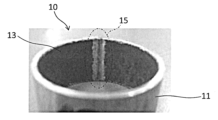
- FIG. 2 is a photographic image of a welded portion of a sliding member according to one embodiment, taken from the outer periphery side.
- FIG. 3 is a photographic image taken from the inner periphery side of an area corresponding to a welded portion of a sliding member according to one embodiment.
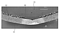
- FIG. 4 is an optical microscope photograph of the cross-sectional structure of the area corresponding to the weld before the sliding layer is formed (resin impregnation and baking).
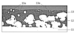
- FIG. 5 is a backscattered electron composition image of a cross-sectional structure of a region other than the welded portion of a sliding member according to one embodiment.
- FIG. 1 is a perspective view showing a schematic configuration of a sliding member according to an embodiment.
- FIG. 2 is a photographic image of a welded portion of a sliding member according to one embodiment, taken from the outer periphery side.
- FIG. 3 is
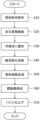
- FIG. 6 is a flow chart showing an example of a method for manufacturing a slide member according to an embodiment.
- FIG. 7 is a flow chart showing another example of the method for producing the slide member according to the embodiment.
- FIG. 8 is a diagram for explaining the raw material powder scattering step and the porous layer sintering step.
- FIG. 9 is a diagram for explaining the raw material resin impregnation step.
- FIG. 10 is a diagram for explaining the burnishing process.
- FIG. 11 is a diagram showing a schematic configuration of a high-speed rotation abrasion tester.
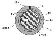
- FIG. 12 is a diagram for explaining the position of the load point (load category A) during measurement in the high-speed rotation wear test for the sliding member according to the example.
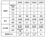
- FIG. 13 is a table showing the compositions and the like of the sliding members according to the examples and comparative examples 1 to 3.
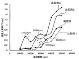
- FIG. 14 is a graph showing the change over time in the bearing temperature measured for the sliding members according to the example and comparative examples 1 to 3 when the shaft rotation speed N was 15,000 rpm.
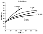
- FIG. 15 is a graph showing the change over time in the bearing temperature measured for the sliding members according to the example and comparative examples 1 to 3 when the shaft rotation speed N was 20,000 rpm.
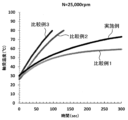
- FIG. 16 is a graph showing the change over time in the bearing temperature measured for the sliding members according to the example and comparative examples 1 to 3 when the shaft rotation speed N was 25,000 rpm.
- FIG. 14 is a graph showing the change over time in the bearing temperature measured for the sliding members according to the example and comparative examples 1 to 3 when the shaft rotation speed N was 15,000 rpm.
- FIG. 15 is a graph showing the change over time in the bearing temperature measured for the sliding members according to the example and comparative examples 1 to 3 when the shaft
- FIG. 17 is a graph showing the change over time in the bearing temperature measured for the sliding members according to the example and comparative examples 1 to 3 when the shaft rotation speed N was 30,000 rpm.
- FIG. 18 is a graph showing the change over time in the bearing temperature measured for the sliding members according to the example and comparative example 1 when the shaft rotation speed N was 35,000 rpm.
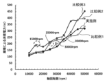
- FIG. 19 is a graph showing the change in temperature rise rate versus shaft rotation speed in the shaft rotation speed range of 10,000 to 50,000 rpm for the sliding members according to the example and comparative examples 1 to 3.
- FIG. 20 is a graph showing the change in power consumption with respect to the shaft rotation speed in the range of 10,000 to 50,000 rpm for the sliding members according to the example and comparative examples 1 to 3.
- FIG. 21 is a graph showing the change in the rate of temperature rise versus the shaft rotation speed in the range near the shaft rotation speed at which a sudden increase in the rate of temperature rise and power consumption occurs for the sliding members according to the example and comparative examples 1 to 3.
- FIG. 22 is a graph showing the change in power consumption with respect to the shaft rotation speed in the range near the shaft rotation speed at which a rapid increase in the temperature increase rate occurs for the sliding members according to the example and comparative examples 1 to 3.
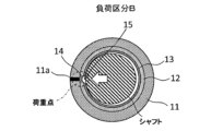
- FIG. 23 is a diagram for explaining the position of the load point (load category B) during measurement in a high-speed rotation wear test for the sliding member according to the example.
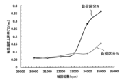
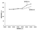
- FIG. 24 is a graph showing the change in temperature rise rate versus shaft rotation speed measured in load sections A and B for the sliding member according to the example.
- FIG. 25 is a graph showing the change in power consumption with respect to the shaft rotation speed measured in each of load categories A and B for the sliding member according to the example.
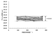
- FIG. 26 is a graph showing the inner diameter accuracy of the sliding member according to the example.
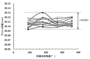
- FIG. 27 is a graph showing the inner diameter accuracy of the sliding member according to Comparative Example 1.
- the slide member according to the first aspect of the embodiment includes: A cylindrical metal substrate; A porous layer formed on the inner circumferential surface of the metal substrate; A sliding layer is provided to cover the porous layer, The porous layer is formed of a metal or an alloy composition, The sliding layer is formed of a resin composition, The resin composition is not present on a part of the inner circumferential surface, and the non-porous layer formed of the metal element or alloy composition is exposed in the region.
- a region is provided in which the resin composition is not present on a part of the inner circumferential surface of the sliding member and the non-porous layer formed of a metal simple substance or an alloy composition is exposed. Since the resin composition is not present in the surrounding area and the non-porous layer does not contain a large number of voids like the porous layer, this region has a concave shape compared to the surrounding area and plays a role like a groove.
- the inner surface of the groove does not contact the shaft that is the sliding object, which contributes to reducing heat generation due to friction. This suppresses temperature rise in the high-speed rotation area and improves the performance of the bearing itself.
- the oil film formation on the sliding surface is maintained by the groove, so that further heat generation reduction is expected compared to use in a dry environment.
- the resin composition is not present on a part of the inner circumferential surface of the sliding member, and a non-porous layer formed of a metal or alloy composition is exposed, and no protrusions due to seams appear on the sliding surface, reducing the torque generated by friction at the seams. This contributes to reducing power consumption and energy loss, and therefore contributes to carbon neutrality.
- an inner diameter cutting step i.e., surface alignment of the inner surface at the seam portion
- the resin composition is not present on a part of the inner peripheral surface of the sliding member, and an area is provided where a non-porous layer formed of a simple metal or an alloy composition is exposed. Therefore, no protrusions due to the seam appear on the sliding surface, and therefore the inner diameter cutting step can be eliminated.
- a slide member according to a second aspect of the embodiment is the slide member according to the first aspect, The region is provided so as to extend from one end to the other end in the axial direction of the sliding member.
- a slide member according to a third aspect of the embodiment is the slide member according to the first or second aspect, In the sliding layer, hard particle powder containing a Laves phase composed of Co, Mo and Si is dispersed.
- a slide member according to a fourth aspect of the embodiment is the slide member according to the third aspect, At least one of MoS2 powder and Laves phase-free bronze powder is further dispersed in the sliding layer.
- a slide member according to a fifth aspect of the embodiment is the slide member according to the first or second aspect
- the resin composition is composed of copper sulfide, a thermoplastic resin, molybdenum disulfide, graphite, aramid fibers, and the balance is a fluororesin, and contains more than 3 mass% and less than 40 mass% of the copper sulfide, 0 mass% or more and less than 4 mass% of the thermoplastic resin, 0 mass% or more and 36 mass% or less of the molybdenum disulfide, 0 mass% or more and 10 mass% or less of the graphite, 0 mass% or more and 10 mass% or less of the aramid fibers, and the balance is the fluororesin.
- a slide member according to a sixth aspect of the embodiment is the slide member according to any one of the first to fifth aspects,
- the porous layer is A matrix phase containing Cu and Sn; and hard particles dispersed in the matrix phase, the hard particles including a Laves phase having a composition of Co, Mo and Si.
- a slide member according to a seventh aspect of the embodiment is the slide member according to the sixth aspect,
- the porous layer is
- the alloy further comprises a compound phase dispersed in the matrix phase, the compound phase including Co, Fe, Ni, Si and Cr.
- a slide member according to an eighth aspect of the embodiment is the slide member according to any one of the first to seventh aspects,
- the ratio of the thickness of the porous layer to the thickness of the sliding layer is 6:4 to 8:2.
- a bearing according to a ninth aspect of the embodiment comprises: A cylindrical metal substrate; A porous layer formed on the inner circumferential surface of the metal substrate; A sliding layer is provided to cover the porous layer, The porous layer is formed of a metal or an alloy composition, The sliding layer is formed of a resin composition, The resin composition is not present on a part of the inner circumferential surface, and the non-porous layer formed of the metal element or alloy composition is exposed in the area.
- a method for producing a slide member includes the steps of: forming a porous layer made of a metal element or an alloy composition on one surface of a metal substrate; rolling the metal substrate with the porous layer on the inside to form a cylindrical shape; a step of welding a joint portion from an outer diameter side of the metal substrate, the porous layer on the joint portion being melted to form a non-porous layer formed of the metal or alloy composition; a step of forming a sliding layer made of a resin composition by impregnating a surface of the porous layer with a raw resin of a sliding layer and baking the raw resin to cover the porous layer, wherein the surface of the non-porous layer is not impregnated with the raw resin, so that the resin composition is not present on a part of the inner circumferential surface of the sliding member, and a region where the non-porous layer is exposed is formed; Includes.
- a method for producing a slide member includes the steps of: forming a porous layer made of a metal element or an alloy composition on one surface of a metal substrate; a step of forming a sliding layer made of a resin composition by impregnating a surface of the porous layer with a raw material resin of a sliding layer and baking the raw material resin to cover the porous layer; rolling the metal substrate with the sliding layer on the inside to form a cylindrical shape; a step of welding a seam portion from an outer diameter side of the metal base material, in which the porous layer on the seam portion is melted to form a non-porous layer formed of the metal element or alloy composition, and the sliding layer on the seam portion is peeled off, thereby forming a region in which the resin composition is not present on a part of the inner circumferential surface of the sliding member and the non-porous layer is exposed; Includes.
- a method according to a twelfth aspect of the embodiment is a method according to the tenth or eleventh aspect, comprising: a step of burnishing the inner circumferential surface of the sliding layer by pressing a cylindrical core metal into the inside of the sliding layer while constraining the outer circumferential surface of the metal base material with a die; Further includes:
- % in relation to the composition means “mass %” unless otherwise specified.
- a to B both A and B are numbers
- main component refers to a component that is contained in an amount of 50 mass % or more of the entire composition.
- hard particle powder refers to a powder in the mixed powder before sintering or a powder dispersed in the resin composition of the sliding layer, and “hard particles” refers to particles in the porous layer after sintering.
- the content of the hard particles in the porous layer varies from the blending amount of the hard particle powder in the mixed powder, and the content of each constituent element in the hard particles differs from the content of each constituent element in the hard particle powder (hard particles are particles with a composition in which the content of Sn and Cu among the chemical components is somewhat lower than that of the hard particle powder).
- the term "seam” refers to a part that connects two objects (or two ends of one object) so that they are continuous, and includes both cases where the object is welded and cases where the object is not welded.
- the term “seam” refers to both cases where the two objects (or two ends of one object) are in contact and cases where the two objects are separated by a small gap.
- the "small gap” is not particularly limited in its specific width, as long as it can be regarded as being connected in a continuous manner when viewed as a whole, but it may be, for example, 1/10 or less of the overall length, 1/50 or less, or 1/100 or less.
- a "seam” that is not welded may also be called a "joint.”
- Fig. 1 is a perspective view showing a schematic configuration of a slide member 10 according to an embodiment.
- Fig. 2 is a photographic image of a welded portion of the slide member 10 taken from the outer periphery side
- Fig. 3 is a photographic image of a region corresponding to the welded portion of the slide member 10 taken from the inner periphery side
- Fig. 4 is an optical microscope photograph of a cross-sectional structure of a region corresponding to the welded portion before forming a sliding layer (resin impregnation and baking).
- Fig. 5 is a backscattered electron composition image of a cross-sectional structure of a region other than the welded portion of the slide member according to an embodiment.
- the upper side of the paper corresponds to the inner periphery side of the slide member 10
- the lower side of the paper corresponds to the outer periphery side of the slide member 10.
- the sliding member 10 is, for example, a sliding bearing, and includes a cylindrical metal substrate 11, a porous layer 12 formed on the inner peripheral surface of the metal substrate 11, and a sliding layer 13 that covers the porous layer 12.
- the porous layer 12 is formed of a simple metal or an alloy composition
- the sliding layer 13 is formed of a resin composition.
- the sliding member 10 as a plain bearing is configured to support the shaft 20, which is the object to be slid, with the sliding layer 13 forming a cylindrical inner peripheral surface.
- the inner diameter roundness of the sliding layer 13 may be 50 ⁇ m or less, or may be 20 ⁇ m or less. In this case, friction on the inner peripheral surface of the sliding layer 13 is reduced, thereby achieving further reductions in wear and heat generation.
- the sliding member 10 can be applied whether the shaft 20 rotates or moves linearly.
- the sliding member 10 may be used in a sliding part where oil is used in a linear motion, such as a shock absorber for an automobile.
- the sliding member 10 may also be used in a sliding part where oil is used in a rotational motion, such as a gear pump that delivers oil by rotating a gear-shaped member.
- a gear pump that delivers oil by rotating a gear-shaped member.
- the metal substrate 11 has a cylindrical shape.
- the metal substrate 11 can be manufactured, for example, by rolling a metal sheet material into a cylindrical shape and then welding the joint portion 11a (see Figure 2).
- the material of the metal substrate 11 is not particularly limited as long as it has sufficient strength and shape stability to be used as a backing metal base material for a bearing, but it can be, for example, low carbon steel (SPCC, SS400, etc.) or a copper-plated steel sheet in which an Fe-based sheet material is plated with Cu.
- the porous layer 12 has a cylindrical shape and is formed by sintering metal powder (a mixed powder described below, or an alloy powder obtained by alloying the mixed powder during spraying) onto the surface of the metal substrate 11.
- the thickness of the porous layer 12 may be a thickness that allows at least two or more pieces of metal powder to be sintered together, and may be, for example, 0.5 mm or less.
- the sliding layer 13 is formed by impregnating the porous layer 12 with a resin composition to a predetermined thickness, and then baking the resin composition impregnated into the porous layer 12.
- the thickness of the sliding layer 13 may be set to be thicker on average than the thickness of the porous layer 12 so that the porous layer 12 is not exposed.
- the ratio of the thickness of the porous layer 12 to the thickness of the sliding layer 13 may be 6:4 to 8:2, and may be, for example, 7:3.
- the resin composition of the sliding layer 13 contains a fluororesin as the main component.
- fluororesin that can be used as the base resin of the resin composition include PTFE (polytetrafluoroethylene), PFA (perfluoroalkoxyalkane), FEP (perfluoroethylene-propylene copolymer), and EFFE (ethylene-tetrafluoroethylene copolymer).
- the resin composition contains PTFE as a main component of the fluororesin, and may contain other fluororesins other than PTFE, such as PFA, as optional additives.
- the content of the other fluororesins contained as optional components may be 0 vol% or more and 20 vol% or less in the resin composition.
- PTFE resin products include Polyflon (registered trademark) D-210C and F-201 (manufactured by Daikin Industries, Ltd.), Fluon (registered trademark) AD911D (manufactured by Asahi Glass Co., Ltd.), and Teflon (registered trademark) 31JR and 6C-J (manufactured by Mitsui DuPont Fluorochemicals Co., Ltd.).
- the resin composition of the sliding layer 13 may have dispersed therein hard particle powder 13a including a Laves phase composed of Co, Mo, and Si.
- the Laves phase is an intermetallic compound based on AB 2 type composed of A element and B element with an atomic radius ratio of about 1.2:1, and has three types of structures: MgZn 2 (C14), MgCu 2 (C15), and MgNi 2 (C36).
- the Laves phase composed of Co, Mo, and Si (more specifically, Co 3 Mo 2 Si) is a Laves phase in which the A element is Mo, the B element is Co, and 25 at % of Co is replaced by Si, and is an MgZn 2 type having a hexagonal crystal structure.
- the Vickers hardness of the Laves phase composed of Co 3 Mo 2 Si is Hv1000 to 1200.
- the hard particle powder 13a dispersed in the sliding layer 13 is considered to receive a higher load than the resin composition forming the sliding layer 13.
- the hard Laves phase composed of Co, Mo, and Si precipitates on the friction surface and supports the load, which can be advantageous in reducing wear of the sliding layer 13.
- a sulfide film of MoS2 can be formed on the friction surface by Mo in the Laves phase and S in the lubricating oil.
- MoS2 is a material known as a sulfide that replaces the solid lubricity of lead and contributes to improving friction characteristics. Compared to the bonds between molybdenum and between molybdenum and sulfur, the bonds between sulfur are weaker when friction occurs, so that lubrication occurs by selectively breaking the bonds between sulfur, which can effectively act to suppress wear.
- Mo oxides generated on the friction surface by oxidation of Mo in the Laves phase during sliding can also exert a lubricating effect and effectively act to suppress wear.
- MoS 2 molybdenum disulfide
- bronze powder not containing a Laves phase may be further dispersed in the resin composition of the sliding layer 13.
- MoS 2 is a material known as a sulfide that substitutes for the solid lubricity of lead and contributes to improving friction characteristics, and since the bond between sulfur is weaker than the bond between molybdenum and between molybdenum and sulfur, when friction occurs, the bond between sulfur is selectively broken, causing lubrication and effectively suppressing wear.
- the resin composition of the sliding layer 13 may be composed of copper sulfide (CuS), thermoplastic resin, molybdenum disulfide ( MoS2 ), graphite, aramid fiber, and the remainder being fluororesin (however, the resin composition does not contain lithium phosphate).
- the resin composition may contain more than 3 mass% and less than 40 mass% copper sulfide, 0 mass% to less than 4 mass% thermoplastic resin, 0 mass% to 36 mass% molybdenum disulfide, 0 mass% to 10 mass% graphite, 0 mass% to 10 mass% aramid fiber, and the remainder being fluororesin.
- the heat dissipation characteristics of the sliding layer 13 are improved. This suppresses the temperature rise of the sliding layer 13 caused by the sliding of the sliding object, and suppresses deformation of the sliding layer 13 due to the temperature rise.
- the strength of the sliding layer 13 is improved. It is known that the strength of the resin layer is improved by including a carbon fiber filler in the resin composition that forms the sliding layer. In contrast, by including copper sulfide in the resin composition, the strength is improved in the same way as when a carbon fiber filler is included, even if no carbon fiber filler is included. The improvement in the strength of the sliding layer 13 also suppresses deformation of the sliding layer 5 due to the sliding of the sliding object.
- Copper sulfide is known as copper (I) sulfide (Cu 2 S) and copper (II) sulfide (CuS). Copper (I) sulfide (Cu 2 S) is stable even at 1000° C. or higher. In contrast, copper (II) sulfide (CuS) changes to copper (I) sulfide (Cu 2 S) at around 200° C.
- the resin composition 4 is heated at a temperature exceeding 327° C. in the step of baking the sliding layer 13. Therefore, when the resin composition contains copper (II) sulfide (CuS), copper (II) sulfide (CuS) changes to copper (I) sulfide (Cu 2 S) in the step of baking the sliding layer 13.
- the slide layer 13 of the slide member 10 which is the manufactured product, contains cuprous sulfide (Cu 2 S).
- cuprous sulfide (Cu 2 S) or cupric sulfide (CuS) may be used as the raw material for copper sulfide, it is preferable to use cupric sulfide (CuS) in view of processability.
- the resin composition forming the sliding layer 13 preferably contains copper sulfide in an amount of more than 8% by mass and less than 40% by mass in order to improve heat dissipation characteristics and strength. If the amount of copper sulfide added is 3% by mass or less or 40% by mass or more, the heat dissipation characteristics deteriorate and the wear resistance characteristics are impaired.
- cupric sulfide manufactured by Terada Yakusen Kogyo Co., Ltd.
- cupric sulfide manufactured by Kanto Kagaku Co., Ltd.
- cuprous sulfide manufactured by Kojundo Kagaku Kenkyusho Co., Ltd.
- thermoplastic resin 0% by mass or more and 4% by mass or less
- a thermoplastic resin is not an essential additive.
- thermoplastic resin When adding thermoplastic resin, if the amount exceeds 4% by mass, it will hinder the low friction characteristics of the fluororesin.
- PPS resins as thermoplastic resins include PQ-208 manufactured by DIC Corporation and Fortron (registered trademark) KPS manufactured by Kureha Corporation.
- graphite 0% by mass or more and 10% by mass or less
- graphite is not an essential additive, but it is expected to contribute to improving self-lubrication and heat resistance, low friction characteristics, and wear resistance characteristics. When graphite is added in an amount exceeding 10 mass %, the low friction characteristics are impaired.
- Commercially available graphite products include UCP and CPB manufactured by Nippon Graphite Industries Co., Ltd., and AT series manufactured by Oriental Sangyo Co., Ltd. can be done.
- Molybdenum sulfide 0 mass% or more and 36 mass% or less
- MoS 2 molybdenum disulfide
- aramid fiber is not an essential additive, but is added to obtain mechanical strength. When aramid fiber is added in an amount of 10 mass% or more, it inhibits uniform dispersion, resulting in a decrease in wear resistance.
- Examples of commercially available products include Kevlar (registered trademark) manufactured by DuPont-Toray Co., Ltd. and Twaron (registered trademark) manufactured by Teijin Co., Ltd.
- the resin composition of the sliding layer 13 may be a zinc compound (ZnS (zinc sulfide), ZnO (zinc oxide), ZnSO 4 (zinc sulfate, etc.), carbon fiber, iron oxide, barium sulfate, aramid fiber, graphite, a calcium compound (CaCO 3 (calcium carbonate), CaSO 4 (calcium sulfate), Ca(OH) 2
- the resin composition may contain any one or more of zinc, zinc alloy, or zinc compound (calcium hydroxide, etc.) as an optional additive.
- the elastic modulus is improved, and deformation of the sliding layer 13 is suppressed, and the sliding layer 13 is deformed by an external force, and the increase or decrease in the contact area can be suppressed.
- the resin composition contains carbon fiber
- the value of the dynamic friction force and the change between the static friction force and the dynamic friction force can be improved, and the sliding characteristics can be improved.
- the resin composition contains iron oxide
- the elastic modulus can be improved in addition to the wear resistance.
- the wear resistance can be increased without inhibiting the improvement of the elastic modulus by the addition of a zinc compound.
- the friction resistance can be reduced without inhibiting the improvement of the elastic modulus by the addition of a zinc compound.
- the resin composition contains a calcium compound, zinc, or zinc alloy, the wear resistance can be improved without inhibiting the improvement of the elastic modulus by the addition of a zinc compound.
- the porous layer 12 may have a matrix phase containing Cu and Sn, and hard particles dispersed in the matrix phase.
- the porous layer 12 may be formed by sintering an alloy powder obtained by alloying the mixed powder when spraying. By making it into an alloy powder, the sintering of the powder is promoted to form necks, and the powders can be sufficiently bonded together. In addition, by making it into an alloy powder, the hard particles are refined and uniformly dispersed in the matrix phase. Note that, when the hard particle powder 13a is dispersed in the sliding layer 13 described above, the porous layer 13 does not need to contain hard particles.
- the matrix phase is a bronze-based alloy containing Cu as the main component and further containing Sn.
- the matrix phase may be composed of a solid solution of Cu, Sn, and Ni.
- Bi particles may be distributed in the crystal grain boundaries of the matrix phase.
- Bi exerts a self-lubricating effect similar to that of Pb in conventional lead bronze at the friction surface where the sliding layer 4 wears and part of the porous layer 3 is exposed, and acts as a lubricant between the two rubbing surfaces, thereby reducing friction.
- the hard particles may contain a Laves phase composed of Co, Mo, and Si.
- the hard particles dispersed in the matrix phase are considered to receive a higher load than the soft bronze that becomes the matrix phase, but the hard Laves phase composed of Co, Mo, and Si precipitates on the friction surface and supports the load, which can be advantageous in reducing wear of the porous layer 12.
- a sulfide film of MoS 2 can be formed on the friction surface by Mo in the Laves phase and S in the lubricating oil.
- MoS 2 is a material known as a sulfide that replaces the solid lubricity of lead and contributes to improving friction characteristics, and since the bond between sulfur is weaker than the bond between molybdenum and between molybdenum and sulfur, when friction occurs, the bond between sulfur is selectively broken, causing lubrication, which can be effective in suppressing wear.
- Mo oxides generated on the friction surface by oxidation of Mo in the Laves phase during sliding can also exert a lubricating effect and can be effective in suppressing wear.
- the content of the hard particles may be, for example, 40% by mass or less when the entire porous layer 12 is taken as 100% by mass.
- the content of the hard particles may be, for example, 0.1% by mass or more. If the content of the hard particles is 0.1% by mass or more, the effect of reducing wear of the porous layer 12 as described above can be obtained.
- the content of the Laves phase composed of Co, Mo, and Si may be, for example, 0.1 to 20% by mass.
- the total content of Cu and Sn may be 99.9% or more when the entire porous layer 12 is taken as 100% by mass.
- the porous layer 3 may further have a compound phase dispersed in the matrix phase.
- the compound phase may contain Co, Fe, Ni, Si, and Cr.
- the formation of the compound phase in the matrix phase can increase the hardness of the matrix phase, which can be advantageous in improving seizure resistance.
- the sliding member 10 has four configurations: (1) a configuration in which the porous layer 12 contains hard particles, but the sliding layer 13 does not contain hard particle powder 13a; (2) a configuration in which the porous layer 12 does not contain hard particles, but the sliding layer 13 contains hard particle powder 13a; (3) a configuration in which the porous layer 12 contains hard particles, and the sliding layer 13 contains hard particle powder 13a; and (4) a configuration in which the porous layer 12 does not contain hard particles, and the sliding layer 13 does not contain hard particle powder 13a.
- the total content of the hard particles and the content of the hard particle powder 13a may be 1 to 20% by mass, for example, 15% by mass.
- the sliding member 10 has a region 15 where the resin composition is not present on a part of the inner circumferential surface, and a non-porous layer 14 (see FIG. 4) formed of a metal element or an alloy composition is exposed.
- a non-porous layer 14 (see FIG. 4) formed of a metal element or an alloy composition is exposed.
- the region 15 where the resin composition is not present may be provided so as to extend from one end to the other end in the axial direction of the sliding member 10.
- the region 15 where the resin composition is not present may be provided on the seam portion 11a (see FIG. 2) of the metal substrate 11.
- the non-porous layer 14 may be formed of the same metal element or alloy composition as the porous layer 12.
- the non-porous layer 14 has a concave inner surface compared to the surrounding area because the metal or alloy composition that constitutes the porous layer 12 has melted.
- the depth D of the concave space in the non-porous layer 14 may be, for example, 0.2 to 0.3 mm.
- the width (length in the circumferential direction) W of the non-porous layer 14 may be 0.1 to 10% of the inner circumference of the sliding member 10. For example, when the inner circumference of the sliding member 10 is 60 to 70 mm, the width W of the non-porous layer 14 may be 1.0 mm to 3.0 mm.
- Fig. 6 is a flow diagram showing an example of a method for manufacturing the slide member 10.
- Fig. 8 is a diagram for explaining the raw material powder scattering step and the porous layer sintering step.
- Fig. 9 is a diagram for explaining the raw material resin impregnation step, and
- Fig. 10 is a diagram for explaining the burnishing step.
- the raw material powder of the porous layer 12 is spread onto one surface of the plate-shaped metal substrate (step S10).
- the raw powder may be a first powder containing Cu and Sn, a mixed powder obtained by mixing the first powder with a hard particle powder containing a Laves phase composed of Co, Mo and Si, or a mixed powder obtained by mixing the first powder, the hard particle powder and a second powder containing Cu, Co, Fe, Ni, Si and Cr.
- the first powder is a bronze-based alloy powder containing Cu as a main component and further containing Sn.
- the first powder may further contain Bi or P. If the first powder contains Bi, Bi particles are precipitated in the matrix phase 10 during sintering of the raw material powder described later (i.e., step S20), and Bi exhibits a self-lubricating effect similar to that of Pb in conventional lead bronze, thereby reducing friction. If the first powder contains P, oxygen mixed in copper can be removed (deoxidized) to suppress hydrogen embrittlement.
- the content of each constituent element of the first powder may be Sn: 10 to 11 mass%, Cu: balance. If Bi is further contained, Bi: 7 to 9 mass%, and if P is contained, P: 0.02 mass% or less is preferable.
- the blending amount of the first powder in the raw material powder is the remainder obtained by subtracting the total blending amount of powders other than the first powder from the blending amount of the entire raw material powder.
- the hard particle powder is an alloy powder containing Cu and a Laves phase composed of Co, Mo, and Si, and contains Cu, Si, Fe, Mo, Co, and Cr.
- the hard particle powder may further contain Sn, for example, 1 mass% or more of Sn.
- the solid phase temperature of hard particle powder that does not contain Sn reaches nearly 1450°C, but by containing Sn, the solid phase temperature of the hard particle powder can be reduced, and the hard particle powder can be solid-phase sintered to the backing metal base material at nearly 800°C.
- the Sn contained in the hard particle powder is dissolved into the Cu-Sn matrix phase side of the first powder during sintering, and is diffusion-bonded.
- the content of each of the constituent elements in the hard particle powder may be Co: 14-20% by mass, Mo: 24-28% by mass, Si: 3-7% by mass, Fe: 2-16% by mass, Cr: 1-10% by mass, and Cu: remainder, when the entire hard particle powder is taken as 100% by mass.
- the content of each of the constituent elements in the hard particle powder may be Co: 14-20% by mass, Mo: 24-28% by mass, Si: 3-7% by mass, Fe: 2-16% by mass, Cr: 1-10% by mass, Sn: 1-15% by mass, and Cu: remainder, when the entire hard particle powder is taken as 100% by mass.
- the blending amount of the hard particle powder may be 1-40% by mass, and preferably 1-3% by mass, when the entire raw material powder is taken as 100% by mass (i.e., when the entire sliding layer 12 is taken as 100% by mass). Because Cu and Sn dissolve from the hard particle powder during sintering, the content of hard particles in the sliding layer 12 varies depending on the amount of hard particle powder mixed in the raw material powder.
- the second powder is an alloy powder containing Cu as the main component, and further containing Co, Fe, Ni, Si and Cr.
- the second powder may further contain Sn, for example, 1 mass% or more of Sn.
- the solidus temperature of the second powder not containing Sn reaches nearly 1240°C, but by containing Sn, the solidus temperature of the second powder can be reduced, and the second powder can be solid-phase sintered to the backing metal base material at nearly 800°C.
- the content of each constituent element in the second powder may be Co: 0.6 to 4.6 mass%, Fe: 1.6 to 5.6 mass%, Ni: 10 to 14 mass%, Si: 0.5 to 4.5 mass%, Cr: 0.5 to 1.5 mass%, Sn: 1 to 15 mass%, and Cu: balance, when the entire second powder is taken as 100 mass%.
- the amount of the second powder may be 2 to 38% by mass, preferably 10 to 38% by mass, and more preferably 17 to 19% by mass, when the raw material powder as a whole is taken as 100% by mass.
- the first powder, the hard particle powder, and the second powder can each be produced by spraying using, for example, a gas atomization method.
- the heat source for melting may be high frequency
- the crucible (with a nozzle at the bottom) may be made of zirconia.
- the particle size of the first powder may be, for example, 45 ⁇ m to 180 ⁇ m.
- the particle size of the hard particle powder may be a fine powder of 53 ⁇ m or less.
- the particle size of the second powder may be 53 ⁇ m to 150 ⁇ m.
- particle size refers to the particle size distribution measured by the laser diffraction/scattering method using a particle size distribution measuring device MT3300EXII manufactured by Microtrac-Bell. This measurement method conforms to the test procedure after the process of extracting powder from paste in "4.2.3 Laser diffraction type particle size distribution measurement test" of JIS Z3284-2.
- the raw powder scattered on the metal substrate 11 is sintered at 800 to 900°C to form the porous layer 12 (step S20).
- the solid-phase temperatures of the hard particle powder and the second powder that do not contain Sn reach approximately 1450°C and 1240°C, respectively.
- the solid-phase temperatures of the hard particle powder and the second powder can be reduced, and the hard particle powder and the second powder can be solid-phase sintered to the metal substrate (backing metal base material) at approximately 800°C.
- the Sn contained in the hard particle powder dissolves in the Cu-Sn matrix phase 10 side of the first powder during sintering, and is diffusion-bonded. As sintering progresses due to powder shrinkage via Sn, solid-solution strengthening by the Sn in the matrix phase 10 and the Sn contained in the hard particle powder occurs, and ultimately a high-strength alloy can be formed.
- the metal substrate 11 is rolled up with the porous layer 12 on the inside to form a cylindrical shape (step S30), and the seam portion 11a is welded from the outer diameter side of the metal substrate 11 (step S40).
- the welding method may be TIG welding (argon gas welding) or laser welding (pulse welding).
- the porous layer 12 above the seam portion 11a melts due to the heat during welding, and the many voids contained in the porous layer 12 are crushed, forming a non-porous layer 14 formed of a simple metal or an alloy composition. No seam appears on the inner diameter surface. In the non-porous layer 14, the apparent volume is reduced by the amount of the voids contained in the porous layer 12, so the inner diameter surface has a concave shape compared to the surrounding porous layer 12.
- the inner surface of the porous layer 12 may be burnished by pressing a cylindrical core metal 42 into the inside of the porous layer 12 while restraining the outer surface of the metal substrate 11 with a die 41 (see FIG. 10).
- the surface of the porous layer 12 is impregnated with the raw resin of the sliding layer 13 (step S50).
- a predetermined amount of the resin composition may be supplied onto the porous layer 12 formed on the inner circumferential surface of the metal substrate 11, and the resin composition may be pressed against the porous layer 12 by the rotation pressure of the impregnation roll, thereby impregnating the porous layer 12 with the resin composition.
- the resin composition supplied onto the porous layer 12 may have at least one of a hard particle powder 13a containing a Laves phase composed of Co, Mo, and Si, and a molybdenum disulfide (MoS 2 ) powder dispersed therein.
- MoS 2 molybdenum disulfide
- the resin composition may contain copper sulfide as an additive, and may further contain molybdenum disulfide, or may contain graphite and aramid fibers as other additives.
- the amount of the resin composition supplied onto the porous layer 12 is an amount that covers the porous layer 12 with a thickness that does not expose the porous layer 12 from the surface of the sliding layer 13 after the resin composition is baked as described below.
- the surface of the non-porous layer 14 is not in a state where the raw resin is impregnated between the pores, but rather the raw resin is simply placed on top of the non-porous layer 14.
- the resin composition is heated at a temperature exceeding the melting point of the resin contained in the resin composition to melt the resin and volatilize the organic solvent, and then the resin is cured to form the sliding layer 13 made of the resin composition that covers the porous layer 12 (step S60).
- Heating the resin composition at a predetermined temperature to form the sliding layer 13 is called baking.
- the melting point of polytetrafluoroethylene used as the resin is 327°C.
- the sliding layer 13 may be baked by heating the resin composition at a temperature exceeding the melting point of polytetrafluoroethylene (for example, 400 to 500°C) using a baking furnace.
- the outer peripheral surface of the metal substrate 11 is constrained by a die 41 while a cylindrical core metal 42 is pressed into the inside of the sliding layer 13, thereby burnishing the inner peripheral surface of the sliding layer 13 to set the inner diameter roundness to 50 ⁇ m or less (step S70).
- FIG. 7 is a flow diagram showing another example of a method for manufacturing the sliding member 10.
- the raw material powder of the porous layer 12 is spread on one surface of the metal substrate (step S10), and then the raw material powder spread on the metal substrate 11 is sintered to form the porous layer 12 (step S20).
- a predetermined amount of resin composition is supplied onto the porous layer 12, and the resin composition is pressed against the porous layer 12 to impregnate the porous layer 12 (step S150).
- the amount of resin composition supplied onto the porous layer 12 is an amount that covers the porous layer 12 to a thickness that prevents the porous layer 12 from being exposed from the surface of the sliding layer 13 after the resin composition is baked, which will be described later.
- the resin composition is heated to a temperature exceeding the melting point of the resin contained in the resin composition to melt the resin and volatilize the organic solvent, and then the resin is cured to form a sliding layer 13 made of the resin composition that covers the porous layer 12 (step S160).
- the metal substrate 11 is rolled up with the sliding layer 13 on the inside to form a cylindrical shape (step S130), and the seam portion 11a is welded from the outer diameter side of the metal substrate 11 (step S140).
- the welding method may be TIG welding (argon gas welding) or laser welding (pulse welding).
- the heat from the welding melts the porous layer 12 above the seam portion 11a, crushing many voids contained in the porous layer 12 and forming a non-porous layer 14 formed of a simple metal or an alloy composition, and the resin composition on the seam portion 11a peels off, forming a region 15 where the resin composition is not present on part of the inner circumferential surface and the non-porous layer 14 is exposed.
- the outer peripheral surface of the metal substrate 11 is constrained by a die 41 while a cylindrical core metal 42 is pressed into the inside of the sliding layer 13, thereby burnishing the inner peripheral surface of the sliding layer 13 to set the inner diameter roundness to 50 ⁇ m or less (step S70).
- the resin composition is not present on a portion of the inner circumferential surface of the sliding member 10, and a region 15 is provided in which the non-porous layer 14 formed of a metal element or an alloy composition is exposed.
- This region is recessed compared to the surrounding area because there is no resin composition present in the surrounding area, and the non-porous layer does not contain many voids like a porous layer, and plays a role like a groove.
- the inner surface of the groove does not come into contact with the shaft that is being slid against, which contributes to reducing heat generation due to friction. This suppresses temperature rise in the high-speed rotation area, and improves the performance of the bearing itself.
- the groove maintains the formation of an oil film on the sliding surface, so heat generation is expected to be further reduced compared to use in a dry environment.
- the resin composition is not present on a portion of the inner circumferential surface of the sliding member 10, and an area 15 is provided where a non-porous layer 14 formed of a metal alone or an alloy composition is exposed, and no protrusions due to seams appear on the sliding surface, reducing the torque generated during friction at the seams. This contributes to reducing power consumption and energy loss, and therefore contributes to carbon neutrality.
- an inner diameter cutting process i.e., surface alignment of the inner surface at the seam portion
- a part of the inner peripheral surface of the sliding member 10 is free of the resin composition, and an area 15 is provided where the non-porous layer 14 formed of a simple metal or alloy composition is exposed, and no protrusions due to the seam appear on the sliding surface, so the inner diameter cutting process can be eliminated.
- the region 15 where the resin composition is not present is provided so as to extend from one end to the other end in the axial direction of the sliding member 10, so that the effect of reducing heat generation due to friction is obtained continuously from one end to the other end in the axial direction. This makes it possible to further suppress temperature rise in the high-speed rotation region.
- the region 15 where the resin composition is not present has a recessed shape compared to the surrounding area and acts like a groove.
- the region 15 is formed by the heat generated during welding when the joint portion 11a of the metal base material 11 is welded, so the number of steps can be reduced compared to when the sliding layer is formed and then processed into an uneven shape.
- bronze powder (irregular shape, brand: CP-301) manufactured by Fukuda Metal Foil and Powder Co., Ltd. was prepared by removing coarse powder having a particle size of 150 ⁇ m or more as the raw material powder for the porous layer 12.
- the chemical composition of the bronze powder was Cu-10Sn.
- the raw powder of the porous layer 12 was spread on a copper-plated steel sheet, and then sintered at 880°C to form the porous layer 12.
- the steel sheet on which the porous layer 12 was formed was slit to a slit width of 67.6 mm.
- the slit steel sheet was shaped into a cylindrical shape from the width direction while applying pressure via a side roll, and the seam of the steel sheet was argon gas welded from the outer diameter side. After welding, the sheet was shaped by water cooling, deburring, and sizing, and cut to a total length of 10 mm to obtain a cylindrical metal substrate 11 on whose inner surface the porous layer 12 was formed.
- an Amsler tester was used to apply a load to the inner surface of the porous layer 12 by pressing a core metal 42 into the inside of the porous layer 12 while restraining the outer surface of the metal substrate 11 with a die 41, thereby correcting the inner surface of the porous layer 12 (burnishing).
- the impregnated resin had a composition of 1.1% by mass of graphite powder, 15% by mass of hard particle powder containing a Laves phase composed of Co, Mo, and Si, and the remainder being PTFE resin, with 15% by mass of MoS2 powder added for the purpose of improving self-lubrication.
- the chemical composition of the hard particle powder was Cu-4.5Sn-5Si-15Fe-16Co-4Cr-26Mo, the particle size was a fine powder under 53 ⁇ m, and the graphite powder was made by Nippon Graphite Co., Ltd. (brand: CPBW-5).
- the resin impregnation method involved applying resin to the inner surface of the porous layer 12 with a spatula, and pressing it with a rolling core of ⁇ 11.7 while impregnating the porous layer 12 with the resin by the rotational pressure of the rolling. After that, the product was fired in a firing furnace at a firing temperature of 480°C and a conveyor speed of 1000 mm/min.
- an Amsler tester was used to apply a load to the inner surface of the sliding layer 13 by pressing a core bar 42 into the inside of the sliding layer 13 while restraining the outer surface of the metal substrate 11 with a die 41, thereby correcting the inner surface of the sliding layer 13 (burnishing).
- the sliding member according to the embodiment was obtained by the above manufacturing process.
- the sliding member according to the embodiment has a weld mark on the outer peripheral surface of the metal substrate 11, which extends from one end to the other end in the axial direction of the sliding member 10, and an area 15 where a non-porous layer 14 where no resin composition is present is exposed on the inner peripheral surface behind the weld mark, which extends from one end to the other end in the axial direction of the sliding member 10.
- Figure 26 is a graph showing the inner diameter measured at angles of 90°, 180°, 270°, and 360° in the circumferential direction for the sliding member according to the embodiment. As shown in Figure 26, the inner diameter precision of the sliding member according to the embodiment was 0.018 mm or less.
- the sliding members according to Comparative Examples 1 and 2 were produced by the manufacturing process described in Japanese Patent Application No. 2023-026107. That is, in Comparative Example 1, a carbon steel round bar was machined on a lathe to an outer diameter of ⁇ 22 mm, an inner diameter of ⁇ 20.62 mm, and a total length of 10.35 mm to obtain a seamless, thin-walled cylindrical metal substrate. In Comparative Example 2, a carbon steel plate material with a length of 67 mm, a width of 11 mm, and a thickness of 0.75 mm was machined into a rolled bushing to obtain a cylindrical metal substrate with a seam of 2 mm or less in width (seam type).
- the metal substrate is pressed into the inside of the housing to bring the seam (joint) into close contact, and then the carbon steel jig is coaxially placed inside the metal substrate pressed into the housing, and the same bronze powder as in the Example was poured into the annular gap of 0.3 mm between the inner surface of the metal substrate and the outer surface of the jig.
- a rotating shaft was connected to the jig and the powder was filled while rotating the jig with a motor. In this state, sintering was performed in a sintering furnace at a sintering temperature of 880°C and a conveyor speed of 230 mm/min.
- the inside of a cylindrical metal substrate in which bronze powder was sintered was impregnated with resin.
- the composition of the impregnated resin was 1.1 mass% graphite powder, 15 mass% hard particle powder containing a Laves phase composed of Co, Mo and Si, and the remainder PTFE resin, and 15 mass% MoS2 powder was added for the purpose of improving self-lubrication.
- the chemical composition of the hard particle powder was Cu-4.5Sn-5Si-15Fe-16Co-4Cr-26Mo, the particle size was 53 ⁇ m or less fine powder, and the graphite powder was made by Nippon Graphite Co., Ltd. (brand: CPBW-5).
- the resin impregnation method was the same as in the above-mentioned examples, and the explanation will be omitted.
- an Amsler tester was used to apply a load to the inner surface of the sliding layer 13, correcting it (burnishing) by pressing a core bar 42 into the inside of the sliding layer while restraining the outer surface of the metal substrate with a die 41.
- FIG. 27 is a graph showing the inner diameter of the sliding member according to Comparative Example 1 measured at angles of 90°, 180°, 270°, and 360° in the circumferential direction. As shown in Figure 27, the inner diameter precision of the sliding member according to the Example was 0.037 mm or less. It is presumed that the powder filling method in which bronze powder particles are filled one by one and sintered, as in Comparative Examples 1 and 2, results in greater variation in the inner diameter compared to the method in which bronze powder is sintered and then shaped into a cylindrical shape, as in the Example.
- Comparative Example 3 the same bronze powder as in the Example and Comparative Examples 1 and 2 was spread on a carbon steel plate material (metal substrate) and sintered to form a porous layer.
- the porous layer was impregnated with a resin composed of 4 mass% graphite powder, 7.25 mass% MoS2 powder, and the remainder PTFE resin, and then the resin was baked to form a sliding layer covering the porous layer, and then rolling was performed.
- the rolled metal substrate was processed into a rolled bush shape with the sliding layer on the inside, to produce a sliding member in which the metal substrate, the porous layer, and the sliding layer all had seams (joints).
- Figure 13 is a table summarizing the compositions of the sliding members of the examples and comparative examples 1 to 3 produced using the above-mentioned procedure.
- FIG. 11 shows a high-speed rotation wear tester. This tester measures the temperature at the back of the bearing when a load and speed are applied to the test material via the mating shaft, and is mainly suitable for evaluating the amount of wear and heat generation in the high-speed range.
- An oil bath is provided in the test section, and the tester is designed to enable evaluation in both oil and non-lubricated environments.
- a spindle motor (model S262B-SJ03, rated output 1.2 kW, rated voltage 200 V, rated current 4.8 A) manufactured by Shino Electric Co., Ltd.
- the spindle motor is water-cooled via a chiller at a flow rate of 0.7 L/min.
- the outer diameter of the mating shaft is ⁇ 11.957mm to 11.975mm, and the inner diameter of the housing is ⁇ 14.000mm to 14.018mm. Both are made of SKD-11 material, with a hardness of HRC58 after full hardening.
- the temperature of the back of the bearing was measured every second with a data logger at a position 1.5mm from the back of the bearing by inserting a thermocouple into a ⁇ 6mm hole.
- this test was evaluated in an unlubricated environment, and frictional heat generation and wear amount were measured against the number of rotations of the shaft.
- the frictional heat generation was evaluated using the bearing temperature rise rate as an evaluation index, and the temperature slope against the time until the bearing back temperature reached 80°C was analyzed by regression analysis.
- the wear amount was calculated by measuring the thickness of the sliding parts before and after the test with a tube micrometer and calculating the thickness change at the load point.
- the shaft rotation speed is said to reach a maximum of 10,000 rpm for the compressor's main shaft and a maximum of around 30,000 rpm for the EV motor. Taking this into consideration, the range was set to 10,000 to 50,000 rpm.
- a radial load of 10 N was applied to the bearing in one direction, taking into account the usage limits of the spindle motor at high speed rotation and safety.
- the target clearance between the bearing and the shaft was set to 0.1 mm, and the shaft was polished to a surface roughness of Ra 0.17 ⁇ m before being subjected to testing.
- the sliding member according to the embodiment has an area 15 on the inner circumferential surface where the resin composition is not present, and as shown in FIG. 12, a position 90° away from the area 15 in the circumferential direction was set as the load point (hereinafter, the position of this load point is referred to as load category A).
- the power can be converted into electric power, and can be expressed as in the following equation (1).
- R is the radius of rotation (m)
- F is the frictional force (N)
- N is the shaft rotation speed (rpm)
- T is the torque (N ⁇ m)
- E is the power (W)
- P is the power rate (W).
- FIG. 14 is a graph showing the change over time of the bearing back temperature measured when the shaft rotation speed N is 15,000 rpm for the sliding members according to the embodiment and comparative examples 1 to 3
- FIG. 15 is a graph showing the change over time of the bearing back temperature measured when the shaft rotation speed N is 20,000 rpm
- FIG. 16 is a graph showing the change over time of the bearing back temperature measured when the shaft rotation speed N is 25,000 rpm
- FIG. 17 is a graph showing the change over time of the bearing back temperature measured when the shaft rotation speed N is 30,000 rpm
- FIG. 18 is a graph showing the change over time of the bearing back temperature measured when the shaft rotation speed N is 35,000 rpm.
- Figure 19 is a graph showing the change in temperature rise rate versus shaft rotation speed in the range of 10,000 to 50,000 rpm for the sliding members of the example and comparative examples 1 to 3, and Figure 20 is a graph showing the change in power consumption versus shaft rotation speed in the same range.
- the shaft rotation speed at which a sudden increase in the temperature rise rate and power consumption occurs is 15,000 rpm for the sliding member of Comparative Example 3, 25,000 rpm for the sliding member of Comparative Example 2, and 30,000 rpm for the sliding member of Comparative Example 1, while it is 35,000 rpm for the sliding member of the Example. Therefore, it was confirmed that the sliding member of the Example has a higher allowable limit rotation speed than the sliding members of Comparative Examples 1 to 3.
- Figure 21 is a graph showing the change in temperature rise rate versus shaft rotation speed in the range close to the shaft rotation speed where the temperature rise rate and power consumption suddenly increase for the sliding members according to the embodiment and comparative examples 1 to 3
- Figure 22 is a graph showing the change in power consumption versus shaft rotation speed in the same range.
- the sliding member of Comparative Example 3 has a nearly constant temperature rise rate and power consumption in the shaft rotation speed range of 7,000 to 8,000 rpm, but rises sharply when the shaft rotation speed exceeds 8,000 rpm, so it can be determined that the allowable limit rotation speed is 8,000 ⁇ 1,000 rpm.
- the sliding member of Comparative Example 2 has a nearly constant temperature rise rate and power consumption in the shaft rotation speed range of 22,000 to 25,000 rpm, but rises sharply when the shaft rotation speed exceeds 25,000 rpm, so it can be determined that the allowable limit rotation speed is 23,500 ⁇ 1,500 rpm.
- the temperature rise rate and power consumption are almost constant in the shaft rotation speed range of 27,000 to 30,000 rpm, but rise sharply when the shaft rotation speed exceeds 30,000 rpm, so it can be determined that the allowable limit rotation speed is 28,500 ⁇ 1,500 rpm.
- the temperature rise rate and power consumption are almost constant in the shaft rotation speed range of 30,000 to 33,000 rpm, but rise sharply when the shaft rotation speed exceeds 33,000 rpm, so it can be determined that the allowable limit rotation speed is 31,500 ⁇ 1,500 rpm.
- Figure 25 is a graph showing the change in temperature rise rate versus shaft rotation speed measured for load categories A and B for the sliding member of the embodiment
- Figure 26 is a graph showing the change in power consumption versus shaft rotation speed.
- load categories A and B have approximately the same temperature rise rate and power consumption changes, but in the shaft rotation speed range of 33,000 rpm or more, load category A has a higher temperature rise rate and power consumption than load category B.
- load category A the temperature rise occurs due to the accumulation of frictional heat at the contact area
- load category B it is presumed that the frictional heat at the contact area is mitigated by the grooves in area 15 where no resin composition is present, making it easier to dissipate, thereby suppressing the temperature rise.
Landscapes
- Engineering & Computer Science (AREA)
- General Engineering & Computer Science (AREA)
- Mechanical Engineering (AREA)
- Chemical & Material Sciences (AREA)
- Materials Engineering (AREA)
- Metallurgy (AREA)
- Manufacturing & Machinery (AREA)
- Composite Materials (AREA)
- Organic Chemistry (AREA)
- Sliding-Contact Bearings (AREA)
- Powder Metallurgy (AREA)
Abstract
Description
円筒状の金属基材と、
前記金属基材の内周面に形成される多孔質層と、
前記多孔質層を被覆する摺動層を備え、
前記多孔質層は、金属単体または合金組成物で形成され、
前記摺動層は、樹脂組成物で形成され、
内周面の一部に前記樹脂組成物が存在せず、前記金属単体または合金組成物で形成された非多孔質な層が露出した領域を有する。
円筒状の金属基材と、
前記金属基材の内周面に形成される多孔質層と、
前記多孔質層を被覆する摺動層を備え、
前記多孔質層は、金属単体または合金組成物で形成され、
前記摺動層は、樹脂組成物で形成され、
内周面の一部に前記樹脂組成物が存在せず、前記金属単体または合金組成物で形成された非多孔質な層が露出した領域を有する。
金属基材の一の面に金属単体または合金組成物からなる多孔質層を形成するステップと、
前記多孔質層を内側として前記金属基材を巻いて円筒状に整形するステップと、
前記金属基材の外径側から継目部分を溶接するステップであって、前記継目部分の上の前記多孔質層が溶融して前記金属単体または合金組成物で形成された非多孔質な層が形成されるステップと、
前記多孔質層の表面に摺動層の原料樹脂を含浸させ、前記原料樹脂を焼成させることで、前記多孔質層を被覆する、樹脂組成物からなる摺動層を形成するステップであって、前記非多孔質な層の表面は前記原料樹脂が含浸された状態にならないため、前記摺動部材の内周面の一部に前記樹脂組成物が存在せず、前記非多孔質な層が露出した領域が形成されるステップと、
を含む。
金属基材の一の面に金属単体または合金組成物からなる多孔質層を形成するステップと、
前記多孔質層の表面に摺動層の原料樹脂を含浸させ、前記原料樹脂を焼成させることで、前記多孔質層を被覆する、樹脂組成物からなる摺動層を形成するステップと、
前記摺動層を内側として前記金属基材を巻いて円筒状に整形するステップと、
前記金属基材の外径側から継目部分を溶接するステップであって、前記継目部分の上の前記多孔質層が溶融して前記金属単体または合金組成物で形成された非多孔質な層が形成されるとともに、前記継目部分の上の前記摺動層が剥離することで、前記摺動部材の内周面の一部に前記樹脂組成物が存在せず、前記非多孔質な層が露出した領域が形成されるステップと、
を含む。
円筒状の金属基材と、
前記金属基材の内周面に形成される多孔質層と、
前記多孔質層を被覆する摺動層を備え、
前記多孔質層は、金属単体または合金組成物で形成され、
前記摺動層は、樹脂組成物で形成され、
内周面の一部に前記樹脂組成物が存在せず、前記金属単体または合金組成物で形成された非多孔質な層が露出した領域を有する。
また、摺動部材の内周面の一部に樹脂組成物が存在せず、金属単体または合金組成物で形成された非多孔質な層が露出した領域が設けられており、摺動面に合わせ目による突起が現れないため、継目での摩擦時に発生するトルクが低減する。これにより、消費電力の低減に貢献し、エネルギーロスを削減する。したがって、カーボンニュートラルに貢献できる。
また、EVモータや電動コンプレッサ等の高回転環境下で使用される軸受について、従来の転がり軸受から本実施形態に係る摺動部材に置き換えることが可能となり、これにより、小型軽量化につながる。
さらに、摺動面に合わせ目のある従来の摺動部材をモータやコンプレッサに適用する際には、内径切削工程(すなわち、継目部分での内面の面合わせ)が必要であったが、本実施形態に係る摺動部材であれば、摺動部材の内周面の一部に樹脂組成物が存在せず、金属単体または合金組成物で形成された非多孔質な層が露出した領域が設けられており、摺動面には合わせ目による突起が現れないため、内径切削工程を削減できる。
前記領域は前記摺動部材の軸方向の一端から他端まで延びるように設けられている。
前記摺動層中には、Co、MoおよびSiの組成で構成されるラーベス相を含む硬質粒子粉末が分散されている。
前記摺動層中には、MoS2粉末と、ラーベス相を含まない青銅粉末のうちの少なくと
も1つ以上がさらに分散されている。
前記樹脂組成物は、硫化銅、熱可塑性樹脂、二硫化モリブデン、黒鉛、アラミド繊維、残部がフッ素樹脂からなり、前記硫化銅を3質量%超40質量%未満、前記熱可塑性樹脂を0質量%以上4質量%未満、前記二硫化モリブデンを0質量%以上36質量%以下、前記黒鉛を0質量%以上10質量%以下、前記アラミド繊維を0質量%以上10質量%以下で含み、残部が前記フッ素樹脂である。
前記多孔質層は、
CuおよびSnを含むマトリックス相と、
前記マトリックス相中に分散している硬質粒子であって、Co、MoおよびSiの組成で構成されるラーベス相を含む硬質粒子と、を有する。
前記多孔質層は、
前記マトリックス相中に分散している化合物相であって、Co、Fe、Ni、SiおよびCrを含む化合物相をさらに有する。
前記多孔質層の厚みと前記摺動層の厚みの比率は、6:4~8:2である。
円筒状の金属基材と、
前記金属基材の内周面に形成される多孔質層と、
前記多孔質層を被覆する摺動層を備え、
前記多孔質層は、金属単体または合金組成物で形成され、
前記摺動層は、樹脂組成物で形成され、
内周面の一部に前記樹脂組成物が存在せず、前記金属単体または合金組成物で形成された非多孔質な層が露出した領域を有する。
金属基材の一の面に金属単体または合金組成物からなる多孔質層を形成するステップと、
前記多孔質層を内側として前記金属基材を巻いて円筒状に整形するステップと、
前記金属基材の外径側から継目部分を溶接するステップであって、前記継目部分の上の前記多孔質層が溶融して前記金属単体または合金組成物で形成された非多孔質な層が形成されるステップと、
前記多孔質層の表面に摺動層の原料樹脂を含浸させ、前記原料樹脂を焼成させることで、前記多孔質層を被覆する、樹脂組成物からなる摺動層を形成するステップであって、前記非多孔質な層の表面は前記原料樹脂が含浸された状態にならないため、前記摺動部材の内周面の一部に前記樹脂組成物が存在せず、前記非多孔質な層が露出した領域が形成されるステップと、
を含む。
金属基材の一の面に金属単体または合金組成物からなる多孔質層を形成するステップと、
前記多孔質層の表面に摺動層の原料樹脂を含浸させ、前記原料樹脂を焼成させることで、前記多孔質層を被覆する、樹脂組成物からなる摺動層を形成するステップと、
前記摺動層を内側として前記金属基材を巻いて円筒状に整形するステップと、
前記金属基材の外径側から継目部分を溶接するステップであって、前記継目部分の上の前記多孔質層が溶融して前記金属単体または合金組成物で形成された非多孔質な層が形成されるとともに、前記継目部分の上の前記摺動層が剥離することで、前記摺動部材の内周面の一部に前記樹脂組成物が存在せず、前記非多孔質な層が露出した領域が形成されるステップと、
を含む。
前記金属基材の外周面をダイスにより拘束しつつ前記摺動層の内側に円柱状の芯金を押し込むことにより、前記摺動層の内周面をバニシ仕上げ(burnishing)するステップ、
をさらに含む。
図1は、一実施の形態に係る摺動部材10の概略構成を示す斜視図である。図2は、摺動部材10の溶接部を外周側から撮影した写真画像であり、図3は、摺動部材10の溶接部に対応する領域を内周側から撮影した写真画像であり、図4は、摺動層形成(樹脂の含浸および焼成)前の溶接部に対応する領域の断面組織の光学顕微鏡写真である。図5は、一実施の形態に係る摺動部材の溶接部以外の領域の断面組織の反射電子組成像である。図4および図5では、紙面上側が摺動部材10の内周側、紙面下側が摺動部材10の外周側に対応している。
摺動層13を形成する樹脂組成物は、放熱特性及び強度を向上させるため、硫化銅を8質量%超40質量%未満で含むことが好ましい。硫化銅の添加量は、3質量%以下及び40質量%以上であれば放熱特性が悪化し、耐摩耗特性を阻害するようになる。なお、市販品としては、寺田薬泉工業社製の硫化第二銅(CuS)、関東化学社製の硫化第二銅(CuS)、高純度化学研究所社製の硫化第一銅(Cu2S)等を挙げることができる。
一変形例に係る摺動層13の樹脂組成物において、熱可塑性樹脂は必須の添加剤ではないが、添加する場合は、フッ素樹脂の欠点である耐摩耗性、耐クリープ特性が改善できるので添加することが好ましい。
一変形例に係る摺動層13の樹脂組成物において、黒鉛は必須の添加剤ではないが、自己潤滑性及び、耐熱性の向上、低摩擦特性と耐摩耗特性に寄与することが期待できる。黒鉛を添加する場合、10質量%を超えると低摩擦特性を阻害するようになる。なお、市販品としては、日本黒鉛工業社製のUCP、CPB、オリエンタル産業社製のATシリーズ等を挙げることができる。
一変形例に係る摺動層13の樹脂組成物において、二硫化モリブデン(MoS2)は必須の添加剤ではないが、添加することにより摩擦抵抗を低下させることが出来る。
一変形例に係る摺動層13の樹脂組成物において、アラミド繊維は必須の添加剤ではないが、機械的強度を得るために添加する。アラミド繊維を添加する場合、10質量%以上添加すると、均一な分散を阻害するようになるので、その結果、耐摩耗特性が低下する。なお、市販品としては、東レ・デュポン社製のケブラー(登録商標)、帝人のトワロン(登録商標)等を挙げることができる。
次に、このような構成を有する摺動部材10を製造する方法の一例について、図6、図8~図10を参照して説明する。図6は、摺動部材10を製造する方法の一例を示すフロー図である。図8は原料粉末散布工程および多孔質層焼結工程を説明するための図である。図9は、原料樹脂含浸工程を説明するための図であり、図10は、バニシ仕上げ工程を説明するための図である。
次に、本実施の形態に係る具体的な実施例について説明する。
まず、多孔質層12の原料粉末として、福田金属箔粉工業(株)製青銅粉末(不定形、銘柄;CP-301)において、粒度150μm以上の粗粉をカットした粉末を準備した。青銅粉末の化学成分はCu-10Snである。
次に、実施例および比較例1~3の摺動部材の性能を高速回転摩耗試験により比較した。図11に高速回転摩耗試験機を示す。本試験機は、供試材に相手軸を介して荷重と速度を与えたときの軸受背面温度を計測し、主に高速領域における摩耗量や発熱評価に適する。試験部にオイルバスを設け、油中と無潤滑双方の環境での評価を可能に設計してある。また高回転評価を実現するため、相手軸Φ6h7にコレクトチャックを介して進桜電機(株)製スピンドルモータ(型式S262B-SJ03、定格出力1.2kW、定格電圧200V、定格電流4.8A)を先端部に直結させた。これにより、軸振れ0.002mm以下の精度で最大60,000rpmまでの評価が可能な装置に設計した。スピンドルモータにはチラーを介して流量0.7L/minで水冷している。
E=P=2π・N・T/60=2π・N・F・R/60・・・式(1)
ここに、Rは回転半径(m)、Fは摩擦力(N)、Nは軸回転速度(rpm)、Tはトルク(N・m)、Eは電力(W)、Pは仕事率(W)である。
図14は、実施例および比較例1~3に係る摺動部材について、軸回転数N=15,000rpmの場合に計測された軸受背面温度の時間変化を示すグラフであり、図15は、軸回転数N=20,000rpmの場合に計測された軸受背面温度の時間変化を示すグラフであり、図16は、軸回転数N=25,000rpmの場合に計測された軸受背面温度の時間変化を示すグラフであり、図17は、軸回転数N=30,000rpmの場合に計測された軸受背面温度の時間変化を示すグラフであり、図18は、軸回転数N=35,000rpmの場合に計測された軸受背面温度の時間変化を示すグラフである。
Claims (12)
- 円筒状の金属基材と、
前記金属基材の内周面に形成される多孔質層と、
前記多孔質層を被覆する摺動層を備え、
前記多孔質層は、金属単体または合金組成物で形成され、
前記摺動層は、樹脂組成物で形成され、
内周面の一部に前記樹脂組成物が存在せず、前記金属単体または合金組成物で形成された非多孔質な層が露出した領域を有する
ことを特徴とする摺動部材。 - 前記領域は前記摺動部材の軸方向の一端から他端まで延びるように設けられている
ことを特徴とする請求項1に記載の摺動部材。 - 前記摺動層中には、Co、MoおよびSiの組成で構成されるラーベス相を含む硬質粒子粉末が分散されている
ことを特徴とする請求項1または2に記載の摺動部材。 - 前記摺動層中には、MoS2粉末と、ラーベス相を含まない青銅粉末のうちの少なくとも1つ以上がさらに分散されている
ことを特徴とする請求項3に記載の摺動部材。 - 前記樹脂組成物は、硫化銅、熱可塑性樹脂、二硫化モリブデン、黒鉛、アラミド繊維、残部がフッ素樹脂からなり、前記硫化銅を3質量%超40質量%未満、前記熱可塑性樹脂を0質量%以上4質量%未満、前記二硫化モリブデンを0質量%以上36質量%以下、前記黒鉛を0質量%以上10質量%以下、前記アラミド繊維を0質量%以上10質量%以下で含み、残部が前記フッ素樹脂である
ことを特徴とする請求項1または2に記載の摺動部材。 - 前記多孔質層は、
CuおよびSnを含むマトリックス相と、
前記マトリックス相中に分散している硬質粒子であって、Co、MoおよびSiの組成で構成されるラーベス相を含む硬質粒子と、を有する
ことを特徴とする請求項1または2に記載の摺動部材。 - 前記多孔質層は、
前記マトリックス相中に分散している化合物相であって、Co、Fe、Ni、SiおよびCrを含む化合物相をさらに有する
ことを特徴とする請求項6に記載の摺動部材。 - 前記多孔質層の厚みと前記摺動層の厚みの比率は、6:4~8:2である、
ことを特徴とする請求項1または2に記載の摺動部材。 - 円筒状の金属基材と、
前記金属基材の内周面に形成される多孔質層と、
前記多孔質層を被覆する摺動層を備え、
前記多孔質層は、金属単体または合金組成物で形成され、
前記摺動層は、樹脂組成物で形成され、
内周面の一部に前記樹脂組成物が存在せず、前記金属単体または合金組成物で形成された非多孔質な層が露出した領域を有する
ことを特徴とする軸受。 - 摺動部材を製造する方法であって、
金属基材の一の面に金属単体または合金組成物からなる多孔質層を形成するステップと、
前記多孔質層を内側として前記金属基材を巻いて円筒状に整形するステップと、
前記金属基材の外径側から継目部分を溶接するステップであって、前記継目部分の上の前記多孔質層が溶融して前記金属単体または合金組成物で形成された非多孔質な層が形成されるステップと、
前記多孔質層の表面に摺動層の原料樹脂を含浸させ、前記原料樹脂を焼成させることで、前記多孔質層を被覆する、樹脂組成物からなる摺動層を形成するステップであって、前記非多孔質な層の表面は前記原料樹脂が含浸された状態にならないため、前記摺動部材の内周面の一部に前記樹脂組成物が存在せず、前記非多孔質な層が露出した領域が形成されるステップと、
を含むことを特徴とする方法。 - 摺動部材を製造する方法であって、
金属基材の一の面に金属単体または合金組成物からなる多孔質層を形成するステップと、
前記多孔質層の表面に摺動層の原料樹脂を含浸させ、前記原料樹脂を焼成させることで、前記多孔質層を被覆する、樹脂組成物からなる摺動層を形成するステップと、
前記摺動層を内側として前記金属基材を巻いて円筒状に整形するステップと、
前記金属基材の外径側から継目部分を溶接するステップであって、前記継目部分の上の前記多孔質層が溶融して前記金属単体または合金組成物で形成された非多孔質な層が形成されるとともに、前記継目部分の上の前記摺動層が剥離することで、前記摺動部材の内周面の一部に前記樹脂組成物が存在せず、前記非多孔質な層が露出した領域が形成されるステップと、
を含むことを特徴とする方法。 - 前記金属基材の外周面をダイスにより拘束しつつ前記摺動層の内側に円柱状の芯金を押し込むことにより、前記摺動層の内周面をバニシ仕上げするステップ、
をさらに含むことを特徴とする請求項10または11に記載の方法。
Priority Applications (3)
| Application Number | Priority Date | Filing Date | Title |
|---|---|---|---|
| US19/470,360 US20260117823A1 (en) | 2023-06-13 | 2024-05-15 | Sliding member and method for producing sliding member |
| EP24823157.3A EP4692578A1 (en) | 2023-06-13 | 2024-05-15 | Sliding member and method for producing sliding member |
| CN202480031091.7A CN121285703A (zh) | 2023-06-13 | 2024-05-15 | 滑动构件和制造滑动构件的方法 |
Applications Claiming Priority (2)
| Application Number | Priority Date | Filing Date | Title |
|---|---|---|---|
| JP2023096877A JP7372585B1 (ja) | 2023-06-13 | 2023-06-13 | 摺動部材および摺動部材を製造する方法 |
| JP2023-096877 | 2023-06-13 |
Publications (1)
| Publication Number | Publication Date |
|---|---|
| WO2024257535A1 true WO2024257535A1 (ja) | 2024-12-19 |
Family
ID=88510011
Family Applications (1)
| Application Number | Title | Priority Date | Filing Date |
|---|---|---|---|
| PCT/JP2024/017877 Ceased WO2024257535A1 (ja) | 2023-06-13 | 2024-05-15 | 摺動部材および摺動部材を製造する方法 |
Country Status (5)
| Country | Link |
|---|---|
| US (1) | US20260117823A1 (ja) |
| EP (1) | EP4692578A1 (ja) |
| JP (1) | JP7372585B1 (ja) |
| CN (1) | CN121285703A (ja) |
| WO (1) | WO2024257535A1 (ja) |
Citations (5)
| Publication number | Priority date | Publication date | Assignee | Title |
|---|---|---|---|---|
| JP2002039183A (ja) * | 2000-05-19 | 2002-02-06 | Asmo Co Ltd | 焼結含油軸受 |
| WO2010134458A1 (ja) * | 2009-05-19 | 2010-11-25 | Ntn株式会社 | 焼結金属軸受と滑り軸受ユニット用軸部材、およびこの軸部材を備えた滑り軸受ユニット |
| JP2018071710A (ja) * | 2016-10-31 | 2018-05-10 | 千住金属工業株式会社 | 摺動部材及び軸受 |
| JP2018179049A (ja) | 2017-04-06 | 2018-11-15 | 日本精工株式会社 | 転がり軸受 |
| JP2023026107A (ja) | 2021-08-12 | 2023-02-24 | テルモ株式会社 | 超音波カテーテル及びプライミング方法 |
Family Cites Families (6)
| Publication number | Priority date | Publication date | Assignee | Title |
|---|---|---|---|---|
| JPH04160224A (ja) * | 1990-10-22 | 1992-06-03 | Nippon Seiko Kk | すべり軸受 |
| JP3446810B2 (ja) * | 1998-04-08 | 2003-09-16 | 株式会社小松製作所 | 複層焼結摺動部材とその製造方法 |
| JP2007263311A (ja) * | 2006-03-29 | 2007-10-11 | Ntn Corp | 動圧軸受装置 |
| JP5267756B1 (ja) * | 2011-12-22 | 2013-08-21 | 千住金属工業株式会社 | 摺動部材及び軸受 |
| JP6313052B2 (ja) * | 2014-01-21 | 2018-04-18 | オイレス工業株式会社 | 滑り軸受 |
| KR20190052694A (ko) * | 2016-09-28 | 2019-05-16 | 에누티에누 가부시기가이샤 | 활주 부재 |
-
2023
- 2023-06-13 JP JP2023096877A patent/JP7372585B1/ja active Active
-
2024
- 2024-05-15 CN CN202480031091.7A patent/CN121285703A/zh active Pending
- 2024-05-15 US US19/470,360 patent/US20260117823A1/en active Pending
- 2024-05-15 EP EP24823157.3A patent/EP4692578A1/en active Pending
- 2024-05-15 WO PCT/JP2024/017877 patent/WO2024257535A1/ja not_active Ceased
Patent Citations (5)
| Publication number | Priority date | Publication date | Assignee | Title |
|---|---|---|---|---|
| JP2002039183A (ja) * | 2000-05-19 | 2002-02-06 | Asmo Co Ltd | 焼結含油軸受 |
| WO2010134458A1 (ja) * | 2009-05-19 | 2010-11-25 | Ntn株式会社 | 焼結金属軸受と滑り軸受ユニット用軸部材、およびこの軸部材を備えた滑り軸受ユニット |
| JP2018071710A (ja) * | 2016-10-31 | 2018-05-10 | 千住金属工業株式会社 | 摺動部材及び軸受 |
| JP2018179049A (ja) | 2017-04-06 | 2018-11-15 | 日本精工株式会社 | 転がり軸受 |
| JP2023026107A (ja) | 2021-08-12 | 2023-02-24 | テルモ株式会社 | 超音波カテーテル及びプライミング方法 |
Non-Patent Citations (1)
| Title |
|---|
| See also references of EP4692578A1 |
Also Published As
| Publication number | Publication date |
|---|---|
| EP4692578A1 (en) | 2026-02-11 |
| JP7372585B1 (ja) | 2023-11-01 |
| US20260117823A1 (en) | 2026-04-30 |
| CN121285703A (zh) | 2026-01-06 |
| JP2024178609A (ja) | 2024-12-25 |
Similar Documents
| Publication | Publication Date | Title |
|---|---|---|
| US10077807B2 (en) | Composite plain bearing, cradle guide, and sliding nut | |
| JP2010216639A (ja) | 冷凍機用圧縮機の軸受装置 | |
| KR102672968B1 (ko) | 미끄럼 이동 부재, 베어링, 미끄럼 이동 부재의 제조 방법, 베어링의 제조 방법 | |
| WO2012147780A1 (ja) | 摺動材料、軸受用合金及び軸受用複層金属材 | |
| JP4122305B2 (ja) | 内燃機関用すべり軸受 | |
| KR101339745B1 (ko) | 소결 금속재 및 이 금속재로 형성된 소결 함유 베어링, 및유체 베어링 장치 | |
| WO2016158373A1 (ja) | 焼結軸受及びその製造方法 | |
| JP7372585B1 (ja) | 摺動部材および摺動部材を製造する方法 | |
| JP7707221B2 (ja) | 摺動部材および摺動部材を製造する方法 | |
| JP5085035B2 (ja) | 焼結金属材、焼結含油軸受、流体軸受装置、及びモータ | |
| JP7125647B1 (ja) | 摺動部材および軸受 | |
| HK40130689A (zh) | 滑动构件和制造滑动构件的方法 | |
| HK40128574A (zh) | 滑动构件和制造滑动构件的方法 | |
| JPH11293304A (ja) | 複層焼結摺動部材とその製造方法 | |
| JP5640885B2 (ja) | スクロール型圧縮機 | |
| JP7862757B1 (ja) | 摺動部材および軸受の製造方法 | |
| HK40111559A (zh) | 滑动构件及轴承 | |
| JP5214555B2 (ja) | 焼結含油軸受 | |
| CN110475982B (zh) | 烧结轴承及其制造方法 | |
| JP2020193626A (ja) | 冷凍機用圧縮機の軸受 | |
| JP2021011626A (ja) | 摺動部材及びそれに用いる分割片 | |
| TWI490421B (zh) | 保持器、深溝球軸承以及密封軸承 | |
| JP2024049227A (ja) | 摺動部材および摺動体 | |
| KR200220116Y1 (ko) | 엔진 크랭크축 베어링 | |
| Gebretsadik | Tribological Behaviour of Pb-free Engine Bearing Materials |
Legal Events
| Date | Code | Title | Description |
|---|---|---|---|
| 121 | Ep: the epo has been informed by wipo that ep was designated in this application |
Ref document number: 24823157 Country of ref document: EP Kind code of ref document: A1 |
|
| WWE | Wipo information: entry into national phase |
Ref document number: 2024823157 Country of ref document: EP |
|
| ENP | Entry into the national phase |
Ref document number: 2024823157 Country of ref document: EP Effective date: 20251104 |
|
| ENP | Entry into the national phase |
Ref document number: 2024823157 Country of ref document: EP Effective date: 20251104 |
|
| ENP | Entry into the national phase |
Ref document number: 2024823157 Country of ref document: EP Effective date: 20251104 |
|
| ENP | Entry into the national phase |
Ref document number: 2024823157 Country of ref document: EP Effective date: 20251104 |
|
| ENP | Entry into the national phase |
Ref document number: 2024823157 Country of ref document: EP Effective date: 20251104 |
|
| ENP | Entry into the national phase |
Ref document number: 2024823157 Country of ref document: EP Effective date: 20251104 |
|
| ENP | Entry into the national phase |
Ref document number: 2024823157 Country of ref document: EP Effective date: 20251104 |
|
| ENP | Entry into the national phase |
Ref document number: 2024823157 Country of ref document: EP Effective date: 20251104 |
|
| NENP | Non-entry into the national phase |
Ref country code: DE |
|
| WWP | Wipo information: published in national office |
Ref document number: 2024823157 Country of ref document: EP |