WO2024257150A1 - 羽根車、送風機及び空気調和機 - Google Patents
羽根車、送風機及び空気調和機 Download PDFInfo
- Publication number
- WO2024257150A1 WO2024257150A1 PCT/JP2023/021682 JP2023021682W WO2024257150A1 WO 2024257150 A1 WO2024257150 A1 WO 2024257150A1 JP 2023021682 W JP2023021682 W JP 2023021682W WO 2024257150 A1 WO2024257150 A1 WO 2024257150A1
- Authority
- WO
- WIPO (PCT)
- Prior art keywords
- chord
- impeller
- blade
- section
- camber
- Prior art date
- Legal status (The legal status is an assumption and is not a legal conclusion. Google has not performed a legal analysis and makes no representation as to the accuracy of the status listed.)
- Ceased
Links
Images





Classifications
-
- F—MECHANICAL ENGINEERING; LIGHTING; HEATING; WEAPONS; BLASTING
- F04—POSITIVE - DISPLACEMENT MACHINES FOR LIQUIDS; PUMPS FOR LIQUIDS OR ELASTIC FLUIDS
- F04D—NON-POSITIVE-DISPLACEMENT PUMPS
- F04D29/00—Details, component parts, or accessories
- F04D29/26—Rotors specially for elastic fluids
- F04D29/32—Rotors specially for elastic fluids for axial flow pumps
- F04D29/38—Blades
- F04D29/384—Blades characterised by form
-
- F—MECHANICAL ENGINEERING; LIGHTING; HEATING; WEAPONS; BLASTING
- F04—POSITIVE - DISPLACEMENT MACHINES FOR LIQUIDS; PUMPS FOR LIQUIDS OR ELASTIC FLUIDS
- F04D—NON-POSITIVE-DISPLACEMENT PUMPS
- F04D17/00—Radial-flow pumps, e.g. centrifugal pumps; Helico-centrifugal pumps
- F04D17/02—Radial-flow pumps, e.g. centrifugal pumps; Helico-centrifugal pumps having non-centrifugal stages, e.g. centripetal
- F04D17/04—Radial-flow pumps, e.g. centrifugal pumps; Helico-centrifugal pumps having non-centrifugal stages, e.g. centripetal of transverse-flow type
-
- F—MECHANICAL ENGINEERING; LIGHTING; HEATING; WEAPONS; BLASTING
- F04—POSITIVE - DISPLACEMENT MACHINES FOR LIQUIDS; PUMPS FOR LIQUIDS OR ELASTIC FLUIDS
- F04D—NON-POSITIVE-DISPLACEMENT PUMPS
- F04D29/00—Details, component parts, or accessories
- F04D29/26—Rotors specially for elastic fluids
- F04D29/28—Rotors specially for elastic fluids for centrifugal or helico-centrifugal pumps for radial-flow or helico-centrifugal pumps
- F04D29/281—Rotors specially for elastic fluids for centrifugal or helico-centrifugal pumps for radial-flow or helico-centrifugal pumps for fans or blowers
-
- F—MECHANICAL ENGINEERING; LIGHTING; HEATING; WEAPONS; BLASTING
- F04—POSITIVE - DISPLACEMENT MACHINES FOR LIQUIDS; PUMPS FOR LIQUIDS OR ELASTIC FLUIDS
- F04D—NON-POSITIVE-DISPLACEMENT PUMPS
- F04D29/00—Details, component parts, or accessories
- F04D29/26—Rotors specially for elastic fluids
- F04D29/28—Rotors specially for elastic fluids for centrifugal or helico-centrifugal pumps for radial-flow or helico-centrifugal pumps
- F04D29/281—Rotors specially for elastic fluids for centrifugal or helico-centrifugal pumps for radial-flow or helico-centrifugal pumps for fans or blowers
- F04D29/282—Rotors specially for elastic fluids for centrifugal or helico-centrifugal pumps for radial-flow or helico-centrifugal pumps for fans or blowers the leading edge of each vane being substantially parallel to the rotation axis
- F04D29/283—Rotors specially for elastic fluids for centrifugal or helico-centrifugal pumps for radial-flow or helico-centrifugal pumps for fans or blowers the leading edge of each vane being substantially parallel to the rotation axis rotors of the squirrel-cage type
-
- F—MECHANICAL ENGINEERING; LIGHTING; HEATING; WEAPONS; BLASTING
- F04—POSITIVE - DISPLACEMENT MACHINES FOR LIQUIDS; PUMPS FOR LIQUIDS OR ELASTIC FLUIDS
- F04D—NON-POSITIVE-DISPLACEMENT PUMPS
- F04D29/00—Details, component parts, or accessories
- F04D29/26—Rotors specially for elastic fluids
- F04D29/28—Rotors specially for elastic fluids for centrifugal or helico-centrifugal pumps for radial-flow or helico-centrifugal pumps
- F04D29/30—Vanes
-
- F—MECHANICAL ENGINEERING; LIGHTING; HEATING; WEAPONS; BLASTING
- F04—POSITIVE - DISPLACEMENT MACHINES FOR LIQUIDS; PUMPS FOR LIQUIDS OR ELASTIC FLUIDS
- F04D—NON-POSITIVE-DISPLACEMENT PUMPS
- F04D29/00—Details, component parts, or accessories
- F04D29/26—Rotors specially for elastic fluids
- F04D29/32—Rotors specially for elastic fluids for axial flow pumps
- F04D29/325—Rotors specially for elastic fluids for axial flow pumps for axial flow fans
- F04D29/326—Rotors specially for elastic fluids for axial flow pumps for axial flow fans comprising a rotating shroud
-
- F—MECHANICAL ENGINEERING; LIGHTING; HEATING; WEAPONS; BLASTING
- F04—POSITIVE - DISPLACEMENT MACHINES FOR LIQUIDS; PUMPS FOR LIQUIDS OR ELASTIC FLUIDS
- F04D—NON-POSITIVE-DISPLACEMENT PUMPS
- F04D29/00—Details, component parts, or accessories
- F04D29/26—Rotors specially for elastic fluids
- F04D29/32—Rotors specially for elastic fluids for axial flow pumps
- F04D29/38—Blades
-
- F—MECHANICAL ENGINEERING; LIGHTING; HEATING; WEAPONS; BLASTING
- F04—POSITIVE - DISPLACEMENT MACHINES FOR LIQUIDS; PUMPS FOR LIQUIDS OR ELASTIC FLUIDS
- F04D—NON-POSITIVE-DISPLACEMENT PUMPS
- F04D29/00—Details, component parts, or accessories
- F04D29/26—Rotors specially for elastic fluids
- F04D29/32—Rotors specially for elastic fluids for axial flow pumps
- F04D29/38—Blades
- F04D29/384—Blades characterised by form
- F04D29/386—Skewed blades
Definitions
- This disclosure relates to impellers, blowers, and air conditioners.
- impellers in which multiple blades are arranged radially (see, for example, Patent Document 1).
- the center in the circumferential direction of the root of the blade is R1
- the center in the circumferential direction of the outer periphery of the blade is R2
- the center of rotation of the blade is O.
- the angle between the line connecting O and R1 and the line connecting O and R2 is 18 to 22 degrees
- the line P connecting R1 and R2 is inclined at an angle of 22 to 27 degrees toward the suction side with respect to a plane perpendicular to the rotation axis passing through R1.
- the impeller of Patent Document 1 has an inflection point within the blade cross section in the shape of the cross section in the circumferential direction of the blade.
- the impeller of Patent Document 1 has a convex shape with a convex discharge side between the leading edge of the blade in the rotation direction and the inflection point, and a concave shape with a concave discharge side between the inflection point and the trailing edge of the blade in the rotation direction.
- the impeller in Patent Document 1 has these convex and concave shapes formed over the entire length of the blades, from the base to the outer periphery.
- the efficiency of an impeller is improved by suppressing separation that occurs on the blade surface.
- the impeller of Patent Document 1 has blades formed in the above-mentioned configuration, and is therefore said to be able to reduce noise caused by the rotation of the blades when the impeller is rotating.
- the impeller of Patent Document 1 has a convex shape on the leading edge side and a concave shape on the trailing edge side over the entire length from the base of the blade to the outer periphery, so there is a risk that separation of the airflow will occur due to the convex shape on the outer periphery side, where the airflow is faster than on the inner periphery side of the impeller, resulting in a deterioration of the air blowing performance.
- the present disclosure is intended to solve the problems described above, and aims to provide an impeller, a blower, and an air conditioner that suppress airflow separation and improve blowing performance.
- the impeller according to the present disclosure comprises a boss portion provided on a rotating shaft and a plurality of blades provided on the outer periphery of the boss portion, and each of the plurality of blades has a leading edge portion which is the edge portion on the forward side in the direction of rotation, a trailing edge portion which is the edge portion on the rearward side in the direction of rotation, an outer peripheral end portion which is the edge portion on the outer periphery, and an inner peripheral edge portion which is the edge portion on the inner periphery.
- each imaginary cross section of the multiple blades corresponding to the cylindrical portion is defined as a chord direction cross section
- a straight line connecting the leading edge portion and the trailing edge portion in the chord direction cross section is defined as a blade chord
- the center line of the blade cross section is defined as a camber line
- the camber line in a direction perpendicular to the blade chord and the blades in the chord direction cross section are defined as a camber line.
- the camber midpoint the position on the camber line where the distance from the leading edge and the trailing edge is equal is defined as the camber midpoint
- the point on the camber line where the camber height is maximum is defined as the maximum extreme point
- the camber line has at least one inflection point between the leading edge and the maximum extreme point, and in a chord direction cross section at a position closer to the outer periphery than the inner periphery of the blade, the maximum extreme point is located on the leading edge side of the camber midpoint and on the air intake side of the chord.
- the blower according to the present disclosure includes a casing having a bellmouth, and an impeller of the above configuration housed inside the casing, and when the extension length of the casing in the axial direction of the rotating shaft is defined as length Hb and the coefficient ⁇ is defined as 0 ⁇ 0.5, the impeller is disposed in a region inside an imaginary plane located a length ⁇ Hb away from the casing on the air suction side and on the air blowing side in the axial direction of the rotating shaft.
- the air conditioner disclosed herein includes an impeller having the above-described configuration and a heat exchanger that exchanges heat between the air supplied by the impeller and the refrigerant circulating inside.
- the impeller, and the impeller of the blower and air conditioner are configured as follows.
- the maximum extreme point is located on the trailing edge side of the camber midpoint and on the air intake side of the blade chord.
- the camber line also has at least one inflection point between the leading edge and the maximum extreme point.
- the maximum extreme point is located on the leading edge side of the camber midpoint and on the air intake side of the blade chord.
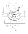
- FIG. 1 is a perspective view showing a configuration of an impeller and a blower including the impeller according to a first embodiment of the present invention
- 1 is a conceptual diagram for explaining the basic configuration of an impeller according to a first embodiment, showing the impeller projected onto a plane perpendicular to the rotation axis.
- FIG. 3 is a conceptual diagram showing a cross section taken along line III-III in FIG. 2 as viewed in the direction of the arrows.
- 2 is a conceptual diagram showing an example of a cross section in the chord direction of a blade of an impeller according to embodiment 1.
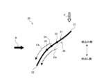
- FIG. 4 is a conceptual diagram showing a chord and a camber line in a section in the chord direction taken along line IV-IV in FIG. 2.
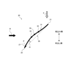
- FIG. 3 is a conceptual diagram showing the chord and camber lines in a section in the chord direction taken along the line VV in FIG. 2.
- FIG. 4 is a conceptual diagram showing the chord and camber lines in a cross section in the chord direction taken along line IV-IV in FIG. 2 for explaining the operation of the impeller and the flow of air currents according to the first embodiment.
- 3 is a conceptual diagram showing the chord and camber lines in a cross section in the chord direction taken along line VV in FIG. 2 for explaining the operation of the impeller and the flow of air currents according to the first embodiment.
- FIG. FIG. 4 is a conceptual diagram showing an impeller according to a second embodiment, illustrating a chord and a camber line in a cross section in the chord direction taken along line IV-IV in FIG.
- FIG. 3 is a conceptual diagram showing an impeller according to a second embodiment, illustrating the chord and camber lines in a cross section in the chord direction taken along line VV in FIG. 2.
- 13 is a graph showing the relationship between the flow coefficient and the fan efficiency of the impeller according to the second embodiment and an impeller of the prior art.
- 13 is a graph showing the relationship between the flow coefficient and the pressure coefficient of the impeller according to the second embodiment and an impeller of the prior art.
- FIG. 4 is a conceptual diagram showing an impeller according to a third embodiment, illustrating a chord and a camber line in a cross section in the chord direction taken along line IV-IV in FIG. 2 .
- FIG. 11 is a conceptual diagram showing the chord and camber lines in a cross section in the chord direction taken along line VV in FIG. 2 of an impeller according to a third embodiment. 1.
- FIG. 11 is a conceptual diagram showing a cross section of a blower according to a fourth embodiment of the present invention, taken along a plane parallel to and passing through a rotation axis of the blower shown in FIG.
- FIG. 13 is a perspective view showing the configuration of an air conditioner according to a fifth embodiment.
- the shape is not chamfered, but the same effect can be obtained even if chamfering is performed. That is, for example, the impeller, blower, and air conditioner can obtain the same effect whether C-chamfering is performed or R-chamfering is performed.
- FIG. 1 is a perspective view showing the configuration of an impeller 10 and a blower 100 including the same according to the first embodiment.
- Fig. 1 shows a part of the configuration of the blower 100 as viewed from the suction side, i.e., the negative pressure surface 26 side of the blade 20.
- a thick black arrow R indicates the rotation direction of the impeller 10, i.e., the rotation direction of the boss portion 12 and the blade 20 which are part of the impeller 10.
- a double-pointed arrow CD in the drawing indicates the circumferential direction of the impeller 10.
- the hollow thick arrow F indicates the overall direction of air flow when the impeller 10 rotates.
- the Y1 side with respect to the impeller 10 is the upstream side of the airflow with respect to the impeller 10
- the Y2 side with respect to the impeller 10 is the downstream side of the airflow with respect to the impeller 10.
- the Y1 side is the air intake side with respect to the impeller 10
- the Y2 side is the air blowing side with respect to the impeller 10.
- the X-axis shown in FIG. 1 is a direction perpendicular to the rotation shaft 11 of the impeller 10, and represents the radial direction of the impeller 10.
- the X2 side portion is located on the outer periphery side of the X1 side portion
- the X1 side portion is located on the inner periphery side of the X2 side portion.
- the X1 side of the impeller 10 is the inner periphery side of the impeller 10
- the X2 side of the impeller 10 is the outer periphery side of the impeller 10.
- the rotation shaft 11 is an imaginary rotation shaft when the impeller 10 rotates.
- the blower 100 according to embodiment 1 is a device that creates an air flow, and is used to blow air.
- the blower 100 according to embodiment 1 is an axial flow blower that blows air in a direction along the rotating shaft 11.
- the blower 100 is used in an air conditioner 200 (see FIG. 16) described below.
- the blower 100 has a casing 80 and an impeller 10.
- the casing 80 forms the outer shell of the blower 100.
- the casing 80 is formed, for example, in a box shape (not shown).
- the casing 80 has a substantially cylindrical bell mouth 81.
- the impeller 10 is disposed on the inner periphery of the bell mouth 81.
- the impeller 10 is arranged so as to be freely rotatable about a rotating shaft 11.
- the blower 100 also has a drive unit (not shown), such as a motor, that rotates the impeller 10.
- Fig. 2 is a conceptual diagram for explaining the basic configuration of the impeller 10 according to the first embodiment, and is a diagram in which the impeller 10 is projected onto a plane perpendicular to the rotation shaft 11. Note that the impeller 10 shown in Fig. 2 is a conceptual diagram used for explaining the basic configuration, and the relative dimensional relationships and shapes of each component may differ from the actual ones. Fig. 2 shows the configuration of the impeller 10 as viewed from the negative pressure surface 26 side of the blade 20. The impeller 10 according to the first embodiment will be explained using Figs. 1 and 2.
- the impeller 10 is an axial flow impeller, and is a device that creates a flow of a fluid such as air.
- the impeller 10 creates a flow of air by rotating around the rotating shaft 11 in the direction of rotation indicated by the thick black arrow R.
- the impeller 10 has a boss portion 12 provided on the rotating shaft 11, and a plurality of blades 20 provided on the outer periphery of the boss portion 12.
- the boss portion 12 has a generally cylindrical shape.
- a drive shaft (not shown) provided in the drive unit is connected to the center of the boss portion 12.
- the boss portion 12 rotates about the rotation axis 11 by a rotational driving force transmitted from the drive unit via the drive shaft.
- the boss portion 12 is rotationally driven by the drive unit to form the rotation axis 11.
- the multiple blades 20 transport air by pushing the air present between the blades 20 as the impeller 10 rotates.
- the multiple blades 20 are arranged at approximately equal angular intervals on the outer circumferential side of the boss portion 12.
- Each of the multiple blades 20 protrudes approximately radially from the outer circumferential wall of the boss portion 12.
- Each of the multiple blades 20 is formed around the boss portion 12 and extends radially outward from the boss portion 12.
- each of the multiple blades 20 protrudes from the outer peripheral wall of the boss portion 12 toward the outer periphery so as to incline forward in the direction of rotation of the impeller 10 with respect to the radial direction centered on the rotating shaft 11. While FIG. 2 illustrates an impeller 10 having four blades 20, the number of blades 20 that the impeller 10 has is not limited to four, and may be less than four or more than four.
- Each of the blades 20 has a leading edge 21, a trailing edge 22, an outer peripheral end 23, and an inner peripheral edge 24.
- the leading edge 21 is the edge of the peripheral edge of the blade 20 that is on the forward side in the direction of rotation.
- the trailing edge 22 is the edge of the peripheral edge of the blade 20 that is on the rearward side in the direction of rotation.
- the outer peripheral end 23 is the edge on the outer peripheral side of the peripheral edge of the blade 20.
- the outer peripheral end 23 forms the outer edge between the leading edge 21 and the trailing edge 22.
- the inner peripheral edge 24 is the edge on the inner peripheral side of the peripheral edge of the blade 20.
- the inner peripheral edge 24 has a shape that follows the outer peripheral wall of the boss portion 12 and is connected to the outer peripheral wall.
- the outer peripheral end 23 and the leading edge 21 are adjacent to each other via the outer peripheral front end 23a.
- the outer peripheral front end 23a is the front end of the outer peripheral end 23 in the rotational direction, and is the outer peripheral end of the leading edge 21 in the radial direction of the rotating shaft 11.
- the outer peripheral end 23 and the trailing edge 22 are adjacent to each other via the outer peripheral rear end 23b.
- the outer peripheral rear end 23b is the rear end of the outer peripheral end 23 in the rotational direction, and is the outer peripheral end of the trailing edge 22 in the radial direction of the rotating shaft 11.
- the inner peripheral edge 24 and the leading edge 21 are adjacent via the inner peripheral front end 24a.
- the inner peripheral front end 24a is the front end of the inner peripheral edge 24 in the rotational direction, and is the inner end of the leading edge 21 in the radial direction of the rotating shaft 11.
- the inner peripheral edge 24 and the trailing edge 22 are adjacent via the inner peripheral rear end 24b.
- the inner peripheral rear end 24b is the rear end of the inner peripheral edge 24 in the rotational direction, and is the inner end of the trailing edge 22 in the radial direction of the rotating shaft 11.
- Each of the multiple blades 20 has a pressure surface 25 and a negative pressure surface 26 as blade surfaces 35.
- the pressure surface 25 is the surface on the front side in the direction of rotation of the two blade surfaces 35 that the blade 20 has. When the blade 20 rotates, the air is pushed by the pressure surface 25.
- the negative pressure surface 26 is the surface on the rear side in the direction of rotation of the two blade surfaces 35 that the blade 20 has, and is the surface behind the pressure surface 25.
- Figures 1 and 2 show the configuration of the blower 100 and the impeller 10, respectively, as seen from the negative pressure surface 26 side, and therefore the pressure surface 25 is indicated by a dashed leading line.
- the surface of the blade 35 facing the upstream side (Y1 side) of the blade 20 becomes the negative pressure surface 26, and the surface facing the downstream side (Y2 side) becomes the pressure surface 25.
- the pressure surface 25 is the surface facing the rotation direction of the blade 20, and the negative pressure surface 26 is the surface facing the opposite side to the rotation direction of the blade 20.
- the multiple blades 20 rotate around the rotating shaft 11 together with the boss portion 12.
- air flows from the front side of the page along the rotating shaft 11 and is sucked into the blower 100.
- the air sucked into the blower 100 flows along the rotating shaft 11 and is blown out from the blower 100 to the back side of the page.
- FIG. 3 is a conceptual diagram of a cross section taken along line III-III in FIG. 2, viewed in the direction of the arrows.
- FIG. 4 is a conceptual diagram showing an example of a chord-direction cross section CS of the blade 20 of the impeller 10 according to embodiment 1.
- FIG. 5 is a conceptual diagram showing the chord 30 and camber line 31 in the chord-direction cross section CS1 taken along line IV-IV in FIG. 2.
- FIG. 6 is a conceptual diagram showing the chord 30 and camber line 31 in the chord-direction cross section CS2 taken along line V-V in FIG. 2.
- the vertical direction represents the direction along the rotating shaft 11
- the upper side represents the suction side
- the lower side represents the blowing side.
- each imaginary cross section of the multiple blades 20 that corresponds to the cylindrical portion is defined as a "chord direction cross section CS.”
- the cross section of the imaginary blade 20 is defined as a "chord direction cross section CS.”
- the blade 20 has a plurality of chord direction cross sections CS in the radial direction centered on the rotating shaft 11.
- chord direction cross section CS shown in FIG. 4 is an example.
- the blade surfaces 35 such as the pressure surface 25 and the suction surface 26 shown in FIG. 4 are an example, and the blade surfaces 35 are not limited to the illustrated form.
- the cross section at the position of line IV-IV in FIG. 2 is the chord direction cross section CS1
- the cross section at the position of line V-V in FIG. 2 is the chord direction cross section CS2.
- the straight line connecting the leading edge 21 and the trailing edge 22 in the chord direction cross section CS is defined as the "chord 30”
- the center line of the blade cross section connecting the leading edge 21 and the trailing edge 22 in the chord direction cross section CS is defined as the "camber line 31”.
- the center line of the blade cross section is the line that passes through the center between the pressure surface 25 and the suction surface 26 in the chord direction cross section CS. Note that in Figures 5 and 6, in order to show the relationship between the chord 30 and the camber line 31, the blade surfaces 35 such as the pressure surface 25 and the suction surface 26 of the blade 20 are not shown, and only the chord 30 and the camber line 31 are shown.
- each of the multiple cord direction cross sections CS the point where the ratio of the distance from the leading edge 21 to the distance from the trailing edge 22 is a constant value is defined as an "imaginary point P.”
- the line connecting each imaginary point P in the multiple cord direction cross sections CS from the inner peripheral edge 24 to the outer peripheral end 23 is defined as a "span line 27" (see Figure 2).
- the ratio of the distance from the leading edge 21 to the distance from the trailing edge 22 is determined based on the required design objectives.
- the distance from each of the leading edge 21 and the trailing edge 22 to the imaginary point P is measured, for example, along the camber line of the blade 20 on the cylindrical cross section. That is, the distance from each of the leading edge 21 and the trailing edge 22 to the imaginary point P is measured, for example, along the camber line 31 of the blade 20 on the chord direction cross section CS. Note that the position of point P shown in Figures 5 and 6 is an example, and is not limited to the position in Figures 5 and 6.
- the direction from the inner peripheral edge 24 toward the outer peripheral end 23 along the span line 27 is defined as the "span direction.”
- a cross section of the blade 20 cut parallel to the rotation axis 11 along the span line 27 is defined as the “span direction cross section SS.”
- the cross section shown in Figure 3 is the span direction cross section SS cut through the blade 20 along one span line 27.
- Span lines 27a, 27b, and 27c shown in FIG. 2 are examples of span lines 27 showing the spanwise cross section SS of the blade 20.
- Span line 27b shown in FIG. 2 is a span line 27 passing through imaginary point P, which is the midpoint between the leading edge 21 and the trailing edge 22 in the chordwise cross section CS, which is the cylindrical cross section of the blade 20.
- the distance between the leading edge 21 and span line 27b is equal to the distance between the trailing edge 22 and span line 27b.
- the distance between the leading edge 21 and imaginary point P is equal to the distance between the trailing edge 22 and imaginary point P.
- Span line 27a shown in FIG. 2 is one of the span lines 27 located closer to the leading edge 21 than span line 27b.
- Span line 27a shown in FIG. 2 is a span line 27 that passes through imaginary point P that is closer to the leading edge 21 than the midpoint between the leading edge 21 and the trailing edge 22 in the chord direction cross section CS, which is a cylindrical cross section of the blade 20.
- the distance between the leading edge 21 and span line 27a is smaller than the distance between the trailing edge 22 and span line 27a.
- the distance between the leading edge 21 and imaginary point P is smaller than the distance between the trailing edge 22 and imaginary point P.
- Span line 27c shown in FIG. 2 is one of the span lines 27 located closer to the trailing edge 22 than span line 27b.
- Span line 27c shown in FIG. 2 is a span line 27 that passes through imaginary point P that is closer to the trailing edge 22 than the midpoint between the leading edge 21 and the trailing edge 22 in the chord direction cross section CS, which is a cylindrical cross section of the blade 20.
- the distance between the leading edge 21 and span line 27c is greater than the distance between the trailing edge 22 and span line 27c.
- the distance between the leading edge 21 and imaginary point P is greater than the distance between the trailing edge 22 and imaginary point P.
- the spanwise cross section SS of the blade 20 on the trailing edge 22 side is convex on the suction side from the inner peripheral edge 24 to the outer peripheral end 23, for example in the entire area between the inner peripheral edge 24 and the outer peripheral end 23.
- the blade 20 on the trailing edge 22 side is curved in the area between the radial intermediate portion 28 and the outer peripheral end 23, such that the suction side is convex from the radial intermediate portion 28 to the outer peripheral end 23 and the blowing side is concave.
- the midpoint between the connection part of the boss 12 with the leading edge 21 and the connection part of the boss 12 with the trailing edge 22 is defined as the "boss midpoint 12a", and the cross section perpendicular to the axial direction of the rotation shaft 11 that passes through the boss midpoint 12a is defined as the "boss midsection 40".
- the distance between the boss midsection 40 and the spanwise cross section SS on the trailing edge 22 side in the axial direction of the rotation shaft 11 is defined as the "trailing edge side blade height Sh”.
- the distance from the chord 30 on the camber line 31 is defined as the "camber height H".
- the camber height H is the distance between the camber line 31 and the chord 30 in a direction perpendicular to the chord 30 in the chord direction cross section CS.
- the point on the camber line 31 where the camber height H is maximum is defined as the "maximum extreme point 33", and the position on the camber line 31 where the distance from the leading edge 21 and the trailing edge 22 are equal is defined as the "camber midpoint 34".
- the maximum extreme point 33 is located closer to the trailing edge 22 than the camber midpoint 34 and closer to the air intake side than the chord 30.
- the camber line 31 has at least one inflection point 32 between the leading edge 21 and the maximum extreme point 33.
- the inflection point 32 is the point where the camber line 31 changes from convex toward the intake side to convex toward the outlet side, or from convex toward the outlet side to convex toward the intake side, as it moves from the leading edge 21 to the trailing edge 22.
- the maximum extreme point 33 is located closer to the leading edge 21 than the camber midpoint 34 and closer to the air intake side than the chord 30.
- the impeller 10 is configured as follows.
- a chord-direction cross section CS1 located closer to the inner circumferential edge 24 of the blade 20 than the outer circumferential edge 23, the maximum extreme point 33 is located closer to the trailing edge 22 than the camber midpoint 34 and closer to the air intake side than the chord 30.
- the camber line 31 has at least one inflection point 32 between the leading edge 21 and the maximum extreme point 33.
- a chord-direction cross section CS2 located closer to the outer circumferential edge 23 of the blade 20 than the inner circumferential edge 24, the maximum extreme point 33 is located closer to the leading edge 21 than the camber midpoint 34 and closer to the air intake side than the chord 30.
- the impeller 10 has this configuration, so that the airflow can be made to follow the blade 20, and therefore separation of the airflow at the leading edge 21 side on the outer circumferential side of the blade 20 can be suppressed. Therefore, the impeller 10 can improve the air blowing performance and increase the air blowing efficiency, thereby achieving high efficiency in fan efficiency.
- the efficiency of the impeller is improved by suppressing separation that occurs on the blade surface.
- the impeller can increase the air volume by increasing the impeller blade area or the rotation speed. However, it is not possible to increase the blade area so that the height of the impeller blades becomes larger than the design constraint, nor is it possible to increase the rotation speed so that the impeller rotates beyond the maximum rotation speed determined by the impeller strength and the upper limit of the motor capacity.
- the circumferential center of the base of the blade is R1
- the circumferential center of the outer periphery of the blade is R2
- the center of rotation of the blade is O.
- the angle between the line connecting O and R1 and the line connecting O and R2 is 18 to 22°
- the line P connecting R1 and R2 is inclined at an angle of 22 to 27° toward the suction side with respect to a plane perpendicular to the rotation axis that passes through R1.
- the impeller blades described in Patent Document 1 have an inflection point within the cross section of the blade in the circumferential cross section of the blade.
- the impeller of Patent Document 1 has a convex shape with a convex surface on the discharge side between the leading edge of the blade in the rotation direction and the inflection point, and a concave shape with a concave surface on the discharge side between the inflection point and the trailing edge of the blade in the rotation direction.
- the impeller of Patent Document 1 is formed so that this convex and concave shape is formed over the entire length from the base of the blade to the outer periphery, so it is said that it can reduce noise caused by the rotation of the blades when the impeller rotates without increasing the height of the blades.
- the magnitude of the rotational component of the airflow passing through the leading edge of the blade is proportional to the radius. Therefore, the magnitude of the rotational component of the airflow passing through the leading edge of the blade is smaller at a position closer to the inner peripheral edge than to the outer peripheral edge than to the inner peripheral edge, and is larger at a position closer to the outer peripheral edge than to the inner peripheral edge than to the outer peripheral edge. In other words, the magnitude of the rotational component of the airflow passing through the leading edge of the blade becomes smaller in the radial direction as it approaches the inner peripheral edge, and becomes larger as it approaches the outer peripheral edge.
- the impeller blades described in Patent Document 1 have a convex shape on the leading edge side and a concave shape on the trailing edge side over the entire length of the blade from the base to the outer periphery, so the convex shape on the outer periphery side, where the airflow is faster, can cause airflow separation and deteriorate the blowing performance. Therefore, it is necessary for the impeller to suppress airflow separation on the leading edge side of the outer periphery of the blade.
- FIG. 7 is a conceptual diagram showing the chord 30 and camber line 31 in the chord-direction cross section CS1 at line IV-IV in FIG. 2 to explain the operation of the impeller 10 and the airflow in embodiment 1.
- the up-down direction in FIG. 7 represents the direction along the rotating shaft 11, with the upper side representing the air intake side and the lower side representing the air blowing side.
- the dashed arrow FA indicates the airflow around the blade 20.
- the maximum extreme point 33 is located closer to the trailing edge 22 than the camber midpoint 34 and closer to the air intake side than the chord 30.
- the impeller 10 can increase the air volume at the same rotation speed of the blade 20 compared to a case not having this configuration.
- the camber line 31 has at least one inflection point 32 between the leading edge 21 and the maximum extreme point 33.
- the impeller 10 can reduce the radius of curvature on the trailing edge 22 side of the blade 20 compared to a case not having this configuration, while at the same time suppressing airflow separation on the leading edge 21 side of the blade 20, thereby increasing the airflow efficiency of the blade 20.
- the impeller 10 can reduce the radius of curvature in the portion of the blade 20 closer to the trailing edge 22 than the leading edge 21, while at the same time suppressing airflow separation in the portion of the blade 20 closer to the leading edge 21 than the trailing edge 22, thereby increasing the airflow efficiency of the blade 20. Therefore, the impeller 10 can achieve higher fan efficiency compared to a case not having the above configuration.
- the impeller 10 can achieve the above effects, such as improving the fan efficiency of the impeller 10 and increasing the air volume at the same rotation speed, without changing the size of the impeller 10.
- FIG. 8 is a conceptual diagram showing the chord 30 and camber line 31 in the chord-direction cross section CS2 at line V-V in FIG. 2 to explain the operation of the impeller 10 and the airflow in embodiment 1.
- the up-down direction in FIG. 8 represents the direction along the rotating shaft 11, with the upper side representing the air intake side and the lower side representing the air blowing side.
- the dashed arrow FA indicates the airflow around the blade 20.
- the maximum extreme point 33 is located closer to the leading edge 21 than the camber midpoint 34 and closer to the air intake side than the chord 30.
- the magnitude of the rotational component of the airflow passing through the leading edge of the blade is proportional to the radius, so the magnitude of the rotational component of the airflow passing through the leading edge of the blade on the outer peripheral end side is greater than the magnitude of the rotational component of the airflow passing through the leading edge of the blade on the inner peripheral edge side.
- the impeller 10 can reduce the radius of curvature on the leading edge 21 side of the blade 20 by having the maximum extreme point 33 located closer to the leading edge 21 than the camber midpoint 34 and closer to the air intake side than the chord 30.
- the impeller 10 can reduce the radius of curvature in the portion closer to the leading edge 21 than the trailing edge 22 of the blade 20 by having the maximum extreme point 33 located closer to the leading edge 21 than the camber midpoint 34 and closer to the air intake side than the chord 30.
- the impeller 10 can increase the static pressure rise on the leading edge 21 side of the blade 20, thereby reducing the pressure gradient from the leading edge 21 side to the trailing edge 22 side of the blade 20.
- the impeller 10 can increase the air volume at the same rotation speed of the blade 20. Therefore, the impeller 10 can achieve higher fan efficiency compared to a case not having the above configuration.
- the impeller 10 can achieve the above effects, such as improving the fan efficiency of the impeller 10 and increasing the air volume at the same rotation speed, without changing the size of the impeller 10.
- FIG. 9 is a conceptual diagram of the impeller 10 according to embodiment 2, showing the chord 30 and the camber line 31 at the chord direction cross section CS1 taken along line IV-IV in Figure 2.
- Figure 10 is a conceptual diagram of the impeller 10 according to embodiment 2, showing the chord 30 and the camber line 31 at the chord direction cross section CS2 taken along line V-V in Figure 2.
- the impeller 10 according to embodiment 2 will be described.
- the impeller 10 according to the second embodiment is characterized by the chord-direction cross section CS of the blades 20 centered on the rotating shaft 11.
- the impeller 10 according to the second embodiment is similar to the impeller 10 according to the first embodiment in terms of configuration other than that described below.
- the characteristics of the impeller 10 according to the second embodiment will be described with reference to the already shown Figures 2, 9, and 10.
- the components having the same functions and actions as those in the first embodiment are given the same reference numerals and their description will be omitted.
- the impeller 10 is formed so that the camber line 31 is located on the air intake side of the chord 30 over the entire area of the blade 20 in the radial direction of the rotating shaft 11.
- the impeller 10 is formed so that the camber line 31 is located on the air intake side of the chord 30 in any chord direction cross section CS from the inner peripheral edge 24 to the outer peripheral end 23 of the blade 20.
- the impeller 10 is formed such that the camber line 31 is located on the air suction side of the blade chord 30 over the entire area of the blade 20 in the radial direction of the rotating shaft 11. Since the impeller 10 is formed such that the camber line 31 is located on the air suction side of the blade chord 30 over the entire area of the blade 20, the amount of pressure rise of the impeller 10 can be increased and the fan efficiency can be improved compared to an impeller not having this configuration.
- the camber line of a part of the blade is formed so that it is located on the air blowing side of the blade chord, the airflow is bent significantly in the opposite direction to the direction in which the boost effect is obtained by that part, and the impeller does not perform the work of the blade. Therefore, if the camber line of a part of the blade is formed so that it is located on the air blowing side of the blade chord, the impeller will have a small boost in pressure. Or, the airflow will not follow the blade at that part, and separation of the airflow will occur, resulting in a deterioration in the fan efficiency of the impeller.
- the blade 20 of the impeller 10 according to embodiment 2 is formed so that the camber line 31 is located on the air intake side of the blade chord 30 over the entire blade 20, so that the boost in pressure of the impeller 10 can be increased and the fan efficiency can be improved compared to an impeller that does not have this configuration.
- FIG. 11 is a graph showing the relationship between flow coefficient and fan efficiency for the impeller 10 according to embodiment 2 and an impeller of the prior art.
- circles indicate the impeller of the prior art, and crosses indicate the impeller 10 of embodiment 2.
- the impeller of the prior art is a general impeller that does not have the characteristics of the impeller 10 of embodiment 2.
- the impeller 10 of embodiment 2 has a higher fan efficiency relative to the flow coefficient in all regions compared to the impeller of the prior art, and therefore has improved fan efficiency compared to the impeller of the prior art.
- FIG. 12 is a graph showing the relationship between the flow coefficient and the pressure coefficient for the impeller 10 according to embodiment 2 and an impeller of the prior art.
- circles indicate the impeller of the prior art
- crosses indicate the impeller 10 according to embodiment 2.
- the impeller of the prior art is a general impeller that does not have the characteristics of the impeller 10 according to embodiment 2.
- the impeller 10 according to embodiment 2 has a higher pressure coefficient relative to the flow coefficient in all regions compared to the impeller of the prior art, and therefore can increase the air volume at the same rotation speed compared to the impeller of the prior art.
- FIG. 13 is a conceptual diagram of the impeller 10 according to embodiment 3, showing the chord 30 and the camber line 31 at the chord direction cross section CS1 taken along line IV-IV in Figure 2.
- Figure 14 is a conceptual diagram of the impeller 10 according to embodiment 3, showing the chord 30 and the camber line 31 at the chord direction cross section CS2 taken along line V-V in Figure 2.
- the impeller 10 according to the third embodiment is characterized by a chord-direction cross section CS of the blades 20 centered on the rotating shaft 11 in the areas close to the inner peripheral edge 24 and the outer peripheral end 23.
- the impeller 10 according to the third embodiment is similar to the impeller 10 according to the first or second embodiment in terms of configuration other than that described below.
- the characteristics of the impeller 10 according to the third embodiment will be described with reference to the already shown Figures 2, 13, and 14.
- the components having the same functions and actions as those in the first or second embodiment are denoted by the same reference numerals and their description will be omitted.
- the camber height H is the distance between the camber line 31 and the chord 30 in the direction perpendicular to the chord 30 in the chord direction cross section CS.
- the distance between the maximum extreme point 33 in the direction perpendicular to the chord 30 and the chord 30 is defined as “distance H h ”.
- the distance between the maximum extreme point 33 in the direction perpendicular to the chord 30 and the chord 30 is defined as “distance Ht ”.
- the impeller 10 is formed so that the distance Ht is greater than the distance Hh . That is, the impeller 10 is formed so as to satisfy the relationship of distance Hh ⁇ distance Ht .
- the magnitude of the rotational component of the airflow passing through the leading edge of the blade is proportional to the radius, so the magnitude of the rotational component of the airflow passing through the leading edge of the blade on the outer peripheral end side is greater than the magnitude of the rotational component of the airflow passing through the leading edge of the blade on the inner peripheral edge side.
- the chord-direction cross section CS is defined, the area of multiple cylindrical cross sections of the blade 20 centered on the rotation axis 11 is proportional to the radius when the axial height is constant, so the chord length can be increased from the inner peripheral edge 24 to the outer peripheral edge 23.
- the impeller 10 can increase the air volume at the same rotation speed. Therefore, by forming the impeller 10 so as to satisfy the relationship of distance Hh ⁇ distance Ht , the static pressure can be further increased on the outer circumferential side of the blades 20 where the magnitude of the airflow is larger than that on the inner circumferential side, compared to a configuration not having this configuration. Therefore, the impeller 10 can increase the air volume at the same rotation speed of the blades 20, compared to a configuration not having this configuration. Therefore, the impeller 10 can achieve high fan efficiency, compared to a configuration not having the above configuration.
- FIG. 15 is a conceptual diagram showing a cross section of blower 100 according to embodiment 4, taken along an arbitrary plane parallel to and passing through rotation shaft 11 of blower 100 shown in Fig. 1. Blower 100 according to embodiment 4 will be described with reference to Fig. 15 and already shown Fig. 1. Note that components having the same functions and actions as those in embodiments 1 to 3 are given the same reference numerals, and description thereof will be omitted.
- the blower 100 according to the fourth embodiment includes a casing 80 having a bellmouth 81, and an impeller 10 according to any one of the first to third embodiments housed inside the casing 80.
- the blower 100 according to the fourth embodiment includes a casing 80 having a bellmouth 81, and an impeller 10 according to any one of the first to third embodiments arranged on the inner circumferential side of the bellmouth 81 when viewed in the axial direction of the rotating shaft 11.
- the casing 80 is formed in a box shape that houses the impeller 10 inside.
- the casing 80 has a bell mouth 81 of a roughly cylindrical shape on both the air blowing side and the air suction side.
- the bell mouth 81 is shaped such that, for example, in the axial direction of the rotating shaft 11, the distance from the rotating shaft 11 increases the further away from the center of the casing 80.
- the casing 80 is shaped such that, for example, in the axial direction of the rotating shaft 11, the distance from the rotating shaft 11 increases due to the bell mouth 81 the further away from the center of the casing 80.
- the bellmouth 81 and the casing 80 are not limited to the above shapes, and may have any shape as long as the distance from the rotating shaft 11 does not decrease as the distance from the center of the casing 80 increases in the axial direction of the rotating shaft 11.
- the casing 80 may have an overall cylindrical shape.
- the length of extension of the casing 80 in the axial direction of the rotating shaft 11 is defined as length Hb .
- the length Hb of the casing 80 is the height of the casing 80.
- the impeller 10 can exert its effect in an area inside an imaginary surface SF that is separated from the casing 80 by a length ⁇ Hb on the air suction side and the air blowing side in the axial direction of the rotating shaft 11.
- the coefficient ⁇ may be greater than 0 and less than or equal to 0.5 (0 ⁇ 0.5).
- the impeller 10 is disposed in an area inside an imaginary surface SF that is separated from the casing 80 by a length ⁇ Hb on the air suction side and the air blowing side in the axial direction of the rotating shaft 11.
- blower 100 can exhibit the effects of impeller 10 by disposing impeller 10 in an area inside a surface that is separated from casing 80 by length ⁇ H b on the air suction side and air blowing side in the axial direction of rotating shaft 11.
- blower 100 according to embodiment 4 can obtain a blower that enables high fan efficiency of impeller 10 and an increase in air volume at the same rotation speed without changing the size.
- FIG. 16 is a perspective view showing the configuration of an air conditioner 200 pertaining to embodiment 5.
- the air conditioner 200 pertaining to embodiment 5 will be described with reference to Fig. 16. Note that components having the same functions and actions as those in embodiments 1 to 4 are given the same reference numerals and descriptions thereof will be omitted.
- an outdoor unit of a multi-air conditioner for a building is exemplified as the air conditioner 200, but the air conditioner 200 is not limited to an outdoor unit of a multi-air conditioner for a building.
- the air conditioner 200 has an impeller 10 according to any one of the first to third embodiments and a blower 100 according to the fourth embodiment that is equipped with the impeller 10.
- the air conditioner 200 also has a housing 203.
- the air conditioner 200 also has a heat exchanger 204 that exchanges heat between the air supplied by the impeller 10 inside the housing 203 and the refrigerant circulating inside.
- the housing 203 is formed in a box shape, for example, in a rectangular parallelepiped shape.
- the shape of the housing 203 is not limited to a rectangular parallelepiped.
- An air outlet 202 is formed in the upper part of the housing 203 for expelling the outdoor air sucked into the inside of the housing 203 to the outside of the air conditioner 200 of the housing 203.
- Each side of the housing 203 is formed with an intake port 201 for drawing in outside air into the housing 203.
- the intake port 201 may be formed on all four sides of the housing 203, or may be formed on one or more of the four sides instead of all four sides.
- the intake port 201 may also be formed on a part of the side of the housing 203, or on the entire side.
- a blower 100 and a heat exchanger 204 are provided in the air passage extending from the intake 201 to the exhaust 202.
- the blower 100 is disposed upstream of the exhaust 202 and downstream of the heat exchanger 204 in the direction of the air flow formed by the blower 100.
- the heat exchanger 204 exchanges heat between the outdoor air and the refrigerant flowing inside the heat exchanger 204 to produce conditioned air.
- the air conditioner 200 when the impeller 10 of the blower 100 rotates, outdoor air is drawn into the interior of the housing 203 through the intake port 201. As this outdoor air passes through the heat exchanger 204, it is heated or cooled by heat exchange with the refrigerant to become conditioned air. This conditioned air that has undergone heat exchange is blown out from the exhaust port 202 to the area to be conditioned.
- blower 100 is more efficient and produces a larger air volume than conventional blowers without changing the size of the impeller. Therefore, air conditioner 200 according to embodiment 5 can operate with improved power efficiency and a larger air volume than conventional blowers without increasing the dimensions of air conditioner 200 compared to conventional air conditioners having a blower other than blower 100.
- the air conditioner 200 includes an impeller 10 according to any one of embodiments 1 to 3, and a heat exchanger 204 that exchanges heat between the air supplied by the impeller 10 and the refrigerant circulating therein.
- the air conditioner 200 includes the impeller 10, and therefore, compared to conventional air conditioners that include an impeller other than the impeller 10, the air conditioner 200 can operate at a large air volume with improved power efficiency without increasing the dimensions of the air conditioner 200.
Landscapes
- Engineering & Computer Science (AREA)
- Mechanical Engineering (AREA)
- General Engineering & Computer Science (AREA)
- Structures Of Non-Positive Displacement Pumps (AREA)
Priority Applications (4)
| Application Number | Priority Date | Filing Date | Title |
|---|---|---|---|
| EP23941462.6A EP4726213A1 (en) | 2023-06-12 | 2023-06-12 | Impeller, blower, and air conditioner |
| CN202380098830.XA CN121285700A (zh) | 2023-06-12 | 2023-06-12 | 叶轮、送风机以及空调机 |
| JP2024501537A JP7483171B1 (ja) | 2023-06-12 | 2023-06-12 | 羽根車、送風機及び空気調和機 |
| PCT/JP2023/021682 WO2024257150A1 (ja) | 2023-06-12 | 2023-06-12 | 羽根車、送風機及び空気調和機 |
Applications Claiming Priority (1)
| Application Number | Priority Date | Filing Date | Title |
|---|---|---|---|
| PCT/JP2023/021682 WO2024257150A1 (ja) | 2023-06-12 | 2023-06-12 | 羽根車、送風機及び空気調和機 |
Publications (1)
| Publication Number | Publication Date |
|---|---|
| WO2024257150A1 true WO2024257150A1 (ja) | 2024-12-19 |
Family
ID=91030965
Family Applications (1)
| Application Number | Title | Priority Date | Filing Date |
|---|---|---|---|
| PCT/JP2023/021682 Ceased WO2024257150A1 (ja) | 2023-06-12 | 2023-06-12 | 羽根車、送風機及び空気調和機 |
Country Status (4)
| Country | Link |
|---|---|
| EP (1) | EP4726213A1 (https=) |
| JP (1) | JP7483171B1 (https=) |
| CN (1) | CN121285700A (https=) |
| WO (1) | WO2024257150A1 (https=) |
Citations (6)
| Publication number | Priority date | Publication date | Assignee | Title |
|---|---|---|---|---|
| JPH02298695A (ja) * | 1989-05-12 | 1990-12-11 | Matsushita Electric Ind Co Ltd | 羽根車 |
| JPH0968200A (ja) | 1995-08-29 | 1997-03-11 | Matsushita Electric Works Ltd | プロペラファン |
| JP2002021798A (ja) * | 2000-06-09 | 2002-01-23 | Lg Electronics Inc | 軸流ファンとモーターが一体化したファンモーター |
| JP2005307788A (ja) * | 2004-04-20 | 2005-11-04 | Mitsubishi Electric Corp | 軸流ファン |
| JP2012052443A (ja) * | 2010-08-31 | 2012-03-15 | Daikin Industries Ltd | プロペラファン |
| JP2022056022A (ja) * | 2020-09-29 | 2022-04-08 | ダイキン工業株式会社 | プロペラファン |
-
2023
- 2023-06-12 JP JP2024501537A patent/JP7483171B1/ja active Active
- 2023-06-12 CN CN202380098830.XA patent/CN121285700A/zh active Pending
- 2023-06-12 EP EP23941462.6A patent/EP4726213A1/en active Pending
- 2023-06-12 WO PCT/JP2023/021682 patent/WO2024257150A1/ja not_active Ceased
Patent Citations (6)
| Publication number | Priority date | Publication date | Assignee | Title |
|---|---|---|---|---|
| JPH02298695A (ja) * | 1989-05-12 | 1990-12-11 | Matsushita Electric Ind Co Ltd | 羽根車 |
| JPH0968200A (ja) | 1995-08-29 | 1997-03-11 | Matsushita Electric Works Ltd | プロペラファン |
| JP2002021798A (ja) * | 2000-06-09 | 2002-01-23 | Lg Electronics Inc | 軸流ファンとモーターが一体化したファンモーター |
| JP2005307788A (ja) * | 2004-04-20 | 2005-11-04 | Mitsubishi Electric Corp | 軸流ファン |
| JP2012052443A (ja) * | 2010-08-31 | 2012-03-15 | Daikin Industries Ltd | プロペラファン |
| JP2022056022A (ja) * | 2020-09-29 | 2022-04-08 | ダイキン工業株式会社 | プロペラファン |
Also Published As
| Publication number | Publication date |
|---|---|
| JPWO2024257150A1 (https=) | 2024-12-19 |
| JP7483171B1 (ja) | 2024-05-14 |
| CN121285700A (zh) | 2026-01-06 |
| EP4726213A1 (en) | 2026-04-15 |
Similar Documents
| Publication | Publication Date | Title |
|---|---|---|
| CN103597288B (zh) | 空气调节机 | |
| US8668460B2 (en) | Turbo fan and air conditioner with turbo fan | |
| US4222710A (en) | Axial flow fan having auxiliary blade | |
| CN108700086B (zh) | 轴流式鼓风机以及室外机 | |
| CN103790859B (zh) | 螺旋桨式风机和具有该螺旋桨式风机的空调 | |
| CN104981365B (zh) | 车辆用空调装置的室外冷却单元 | |
| WO2017026143A1 (ja) | 送風機および空気調和装置 | |
| CN110914553A (zh) | 叶轮、送风机及空调装置 | |
| JP7337308B1 (ja) | 羽根車、送風機及び空気調和機 | |
| CN110506164B (zh) | 螺旋桨式风扇及空调装置用室外机 | |
| JP7483171B1 (ja) | 羽根車、送風機及び空気調和機 | |
| JP6723434B2 (ja) | プロペラファン | |
| CN104685218A (zh) | 螺旋桨式风扇 | |
| JP4423921B2 (ja) | 遠心送風機及びこれを用いた空気調和機 | |
| CN110892201B (zh) | 空气调节机 | |
| CN113167291B (zh) | 螺旋桨式风扇 | |
| WO2015063850A1 (ja) | 貫流ファン及び空気調和機 | |
| WO2022158108A1 (ja) | プロペラファン、及び空気調和機 | |
| WO2017068724A1 (ja) | 空気調和装置の室外ユニット | |
| WO2026023105A1 (ja) | 羽根車、送風機、及び、空気調和機 | |
| CN113167290B (zh) | 叶轮、送风机以及空调机 | |
| CN113056612B (zh) | 螺旋桨式风扇 | |
| CN110748984B (zh) | 送风风机、空调室外机和空调器 | |
| WO2022249270A1 (ja) | プロペラファン及び空気調和機 | |
| WO2025094261A1 (ja) | 送風機及び室外機 |
Legal Events
| Date | Code | Title | Description |
|---|---|---|---|
| WWE | Wipo information: entry into national phase |
Ref document number: 2024501537 Country of ref document: JP |
|
| 121 | Ep: the epo has been informed by wipo that ep was designated in this application |
Ref document number: 23941462 Country of ref document: EP Kind code of ref document: A1 |
|
| ENP | Entry into the national phase |
Ref document number: 2023941462 Country of ref document: EP Effective date: 20260112 |
|
| WWE | Wipo information: entry into national phase |
Ref document number: 2023941462 Country of ref document: EP |
|
| NENP | Non-entry into the national phase |
Ref country code: DE |
|
| ENP | Entry into the national phase |
Ref document number: 2023941462 Country of ref document: EP Effective date: 20260112 |
|
| ENP | Entry into the national phase |
Ref document number: 2023941462 Country of ref document: EP Effective date: 20260112 |
|
| ENP | Entry into the national phase |
Ref document number: 2023941462 Country of ref document: EP Effective date: 20260112 |
|
| ENP | Entry into the national phase |
Ref document number: 2023941462 Country of ref document: EP Effective date: 20260112 |
|
| WWP | Wipo information: published in national office |
Ref document number: 2023941462 Country of ref document: EP |