WO2024253115A1 - 薬剤包装切り離し装置 - Google Patents
薬剤包装切り離し装置 Download PDFInfo
- Publication number
- WO2024253115A1 WO2024253115A1 PCT/JP2024/020455 JP2024020455W WO2024253115A1 WO 2024253115 A1 WO2024253115 A1 WO 2024253115A1 JP 2024020455 W JP2024020455 W JP 2024020455W WO 2024253115 A1 WO2024253115 A1 WO 2024253115A1
- Authority
- WO
- WIPO (PCT)
- Prior art keywords
- drug packaging
- drug
- strip
- pair
- piece
- Prior art date
- Legal status (The legal status is an assumption and is not a legal conclusion. Google has not performed a legal analysis and makes no representation as to the accuracy of the status listed.)
- Ceased
Links
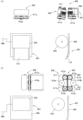
Images

















Classifications
-
- B—PERFORMING OPERATIONS; TRANSPORTING
- B65—CONVEYING; PACKING; STORING; HANDLING THIN OR FILAMENTARY MATERIAL
- B65B—MACHINES, APPARATUS OR DEVICES FOR, OR METHODS OF, PACKAGING ARTICLES OR MATERIALS; UNPACKING
- B65B61/00—Auxiliary devices, not otherwise provided for, for operating on sheets, blanks, webs, binding material, containers or packages
- B65B61/04—Auxiliary devices, not otherwise provided for, for operating on sheets, blanks, webs, binding material, containers or packages for severing webs, or for separating joined packages
- B65B61/12—Auxiliary devices, not otherwise provided for, for operating on sheets, blanks, webs, binding material, containers or packages for severing webs, or for separating joined packages by tearing along perforations or lines of weakness
-
- B—PERFORMING OPERATIONS; TRANSPORTING
- B65—CONVEYING; PACKING; STORING; HANDLING THIN OR FILAMENTARY MATERIAL
- B65B—MACHINES, APPARATUS OR DEVICES FOR, OR METHODS OF, PACKAGING ARTICLES OR MATERIALS; UNPACKING
- B65B2220/00—Specific aspects of the packaging operation
- B65B2220/22—Interconnected packages concurrently produced from the same web, the packages not being separated from one another
Definitions
- the present invention relates to a drug packaging separation device that separates individual drug packages from a drug packaging band in which drug packages are connected in a band shape.
- the medicine packaging device 100 disclosed in Patent Document 1 has a medicine packaging paper holding means 102 that holds roll-shaped packaging paper 101 (medicine packaging paper), a hopper 103, and a bag forming device 105, as shown in Figure 17 (a).
- the drug packaging device 100 is a device that folds a packing paper 101 in half and presses, fuses, or otherwise seals the folded packing paper 101 so that it cannot be separated, forming a bag shape. Drugs are then poured from a hopper 103 into the space between the inner surfaces of the folded packing paper 101, and the area around the part where the drug has been poured is closed (sealed) to create the drug package 110.
- a plurality of medicine packages are discharged in the form of a medicine packaging band 120 in which the medicine packages are connected in a band shape.
- Medicine packaging strip 120 has a plurality of storage sections 121 for storing medicines that are provided continuously with joint regions 122 interposed therebetween.
- One side of medicine packaging strip 120 has common seal section 125 formed by overlapping and fusing the long sides of packing papers 101.
- Joint region 122 is formed by overlapping and fusing the middle sections of packing papers 101.
- a perforation 126 is provided in the joint region 122 of the drug packaging strip 120. The perforation 126 is a tear-off line with low strength.
- the perforation 126 extends in the width direction of the drug packaging strip 120 and is provided in a region corresponding to the storage section 121.
- the perforation 126 does not reach the common seal section 125, and the common seal section 125 becomes a seal section 130 without a tear-off line. That is, the perforation (weak separation line) 126 is provided from the portion 131 corresponding to the bottom of the bag to just before the common seal portion 125 , and there is no perforation 126 in the common seal portion 125 .
- the drug packages were separated from the drug packaging strip 120 by hand. That is, the joining area 122 was divided by hand at the perforations 126, and the drug packages 110 were individually separated from the drug packaging strip 120.
- the present invention is made to meet this demand, and has an object to provide a drug package separation device that separates individual drug packages from a drug package band in which drug packages are connected in a band shape.
- a pharmaceutical packaging separation device that separates pharmaceutical packages from a pharmaceutical packaging band in which the pharmaceutical packages are connected in a band-like shape
- the pharmaceutical packaging separation device having a pair of contact parts that contact the same surface of the pharmaceutical packaging band, a contact piece, one of the contact parts being on the contact piece, a pressing means for pressing the contact piece against the pharmaceutical packaging band, the contact piece moving or changing its position due to the force applied by the pressing means to the contact piece, and the spacing between the contact parts increasing.
- the drug packaging separation device of this embodiment has a pair of abutting parts that contact the drug packaging strip. Although not limited thereto, it is preferable that the pair of abutting parts are set so as to contact the same surface of the drug packaging strip with the perforation of the drug packaging strip sandwiched between them.
- the abutting parts widen the distance between the abutting parts when they are in contact with the drug packaging strip. Therefore, the drug packaging strip is biased in a direction to separate the drug packaging. As a result, the drug packaging strip is pulled left and right with the perforation sandwiched between them, and is torn off from the perforation.
- the force applied by the pressing means to the abutment piece causes the abutment piece to move or change position, thereby widening the space between the abutment portions, so no power is required to widen the space between the abutment portions.
- each of the pair of abutment pieces moves or changes its position to increase the distance between the abutment parts.
- abutment pieces it is desirable to have a pair of abutment pieces, the abutment pieces having the abutment portions, a pressing means for pressing the abutment pieces against the drug packaging strip, and the abutment pieces moving or changing position due to the force of the pressing means pressing the abutment pieces, widening the gap between the abutment portions.
- abutment pieces having the abutment portions, the abutment portions being biased in a direction in which they approach each other by an elastic member, a pressing means for pressing the abutment pieces against the drug packaging strip, and the force of the pressing means pressing the abutment pieces causing the abutment pieces to move or change position against the elastic member, widening the distance between the abutment portions.
- the contact portion rotates around a rotation axis, the contact portion is offset from the rotation axis, and the contact portion moves due to the force of the contact portion being pressed against the drug packaging strip.
- a lateral component force is generated in the medicine packaging strip at the contact portion, and the distance between the contact portions is increased.
- a component force is generated at the contact portion toward the upstream or downstream side of the transport direction of the medicine packaging strip. Therefore, the distance between the contact portions is increased.
- the drug packaging strip is torn into an upstream portion and a downstream portion.
- the contact portion prefferably has a length at least equivalent to the width of the drug packaging strip.
- the drug packaging can be completely separated.
- the abutting portions have a certain length, and that the normal spacing between the abutting portions and/or the spacing between the abutting portions when the spacing widens varies in the longitudinal direction of the abutting portions.
- the medicine packaging strip tears first in the area where the abutting parts are spaced apart, and the area that can be separated gradually expands. Therefore, the pulling force is not dispersed, and the medicine packaging can be separated with a small force.
- the normal distance between the abutting parts and the distance between the abutting parts when the distance is widened are different, so that the drug packaging can be suitably separated with a simple operation and without a lot of time.
- the abutting portions have a certain length, and that the normal spacing between the abutting portions and/or the spacing between the abutting portions when the spacing is increased is narrower at one end and wider at the other end, and that the protruding piece is located on the side where the spacing is narrower.
- the pharmaceutical packaging strip tears first in the areas where the contact parts are spaced apart, and the area that can be separated gradually expands.
- the contact portion holds the front and back of the drug packaging strip and pulls the drug packaging strip in this state, allowing the drug packaging to be separated more reliably.
- a separation section and a feed device the separation section having the pair of abutment sections, the feed device moving the drug packaging strip toward the separation section, and a pressing means for pressing the drug packaging strip upstream of the separation section.
- the pharmaceutical packaging separation device of this embodiment has a feed device, which moves the pharmaceutical packaging strip toward the separation section.
- a pressing means for pressing the pharmaceutical packaging strip is provided upstream of the separation section, so that the pharmaceutical packaging strip is not likely to float up and can be cut smoothly.
- the drug packaging strip has a weak separation line along which the drug packages are separated into individual pieces, and that the drug packaging strip has a feed device that moves the drug packaging strip so that the separation line is positioned between the pair of contact portions.
- the separation line of the drug packaging strip is positioned between a pair of contact parts, so the drug packaging strip is pulled by the pair of contact parts, sandwiching the separation line. This allows the drug packaging strip to be cut smoothly.
- the distance between the contact parts increases when the contact parts are in contact with the medicine packaging strip, and the medicine packaging strip is biased in a direction to separate the medicine packaging.
- the medicine packaging strip is pulled left and right across the perforation and torn off from the perforation.
- the drug packaging separation device of this embodiment has a protruding piece that biases a part of the drug packaging strip. Therefore, the protruding piece forms a tearing starting point in the part of the drug packaging strip. Therefore, even if there is a sealed portion without a perforation, the tearing will proceed from the starting point, and the drug packaging will be separated from the drug packaging strip.
- the drug packaging separation device of this embodiment has a protruding piece, which forms a cut in part of the drug packaging strip.
- the protruding piece forms a cut in part of the drug packaging strip that serves as the starting point for tearing. Therefore, even if there is a sealed portion without perforations, the cut formed by the protruding piece will be used as a starting point to continue tearing, and the drug packaging will be separated from the drug packaging strip.
- the protruding piece is located between the pair of abutment portions.
- the pair of abutting parts are set so as to contact the same side of the pharmaceutical packaging strip, sandwiching the perforation of the pharmaceutical packaging strip.
- the protruding piece since there is a protruding piece between the abutting parts, the protruding piece is on the perforation or on an extension of the perforation. Therefore, even if there is a sealed portion without a perforation, the cut formed by the protruding piece will be used as a starting point to cut and separate the pharmaceutical packaging from the pharmaceutical packaging strip.
- the protruding piece prefferably be a plate-like piece with a pointed tip.
- the protruding piece has a sharp tip, so it is easy to make a cut in the drug packaging strip. Also, when tearing the drug packaging strip, the area held down by the protruding piece can be used as the starting point to tear the strip cleanly.
- the contact portion has a length at least equivalent to the width of the drug packaging strip, and that the protruding piece is located near the end of the contact portion.
- the protruding piece creates a cut in the sealed portion or in its vicinity. This cut then acts as a starting point for further cutting, separating the drug packaging from the drug packaging strip.
- the drug packaging strip has a plurality of storage sections for storing drugs that are arranged continuously with a joint area therebetween, the joint area has a weak separation line that extends in the width direction of the drug packaging strip, there is a seal section near the end of the drug packaging strip in the width direction where the separation line is not present, and it is desirable that the protruding piece is provided at a position that abuts at least a part of the seal section.
- the protruding piece creates a cut in the seal portion. This cut then acts as a starting point for further cutting, separating the drug packaging from the drug packaging strip.
- a reel storage area in which multiple reels with drug packaging strips wound around them are installed, a separation section in which an abutment is installed and which separates the drug packaging from the drug packaging strip supplied from the reel, and a transport means for transporting the drug packaging separated by the separation section, with the reel storage area being located above the separation section and the transport means being located below the separation section.
- the drug packaging separation device of this embodiment has a reel storage area in which multiple reels with drug packaging strips wound around them are installed, so that, for example, drug packages for multiple patients can be loaded at one time, and operation can be performed continuously.
- the medicine packaging separation device of this aspect the medicine packaging separated by the separation section can be transported by the transport means.
- the medicine packaging separating device of this embodiment has a structure in which parts each having an individual function are stacked vertically, and therefore occupies a small area.
- the separation section is movable and can be moved to the lower side of any reel.
- multiple reels can be selected and the drug packaging strip wound on the reels can be separated into individual drug packages.
- the conveying means to hold the drug packaging, move it in a straight line, and release the drug packaging at a predetermined position.
- the drug packaging can be moved to a specified position.
- a holding member that holds one side of the drug packaging and a position change means that changes the position of the holding member, and to hold the drug packaging in a vertical position with the holding member and then change the position of the drug packaging to a horizontal position with the position change means.
- the drug packaging can be moved to a specified position.
- the device has a straightening means that continuously folds a portion of the drug packaging strip.
- This embodiment can remove any bending of the drug packaging strip.
- the straightening means is composed of a roller having a ridge on its circumferential surface and a roller having a groove on its circumferential surface.
- This embodiment allows the medicine packaging strip to be continuously straightened out.
- the drug packaging separation device of the present invention makes it possible to separate individual drug packages from a drug packaging band in which drug packages are connected in a band-like shape without manual intervention.
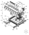
- FIG. 1 is a perspective view of a medicine packaging separation device according to an embodiment of the present invention.
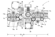
- FIG. 2 is a front view of the medicine packaging separating device of FIG. 1 .
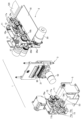
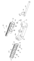
- FIG. 2 is an exploded perspective view of the drug packaging and separating device of FIG. 1.
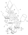
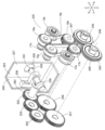
- FIG. 2 is a mechanical diagram of a feeding device of the medicine packaging separating device of FIG. 1 .
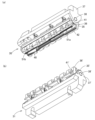
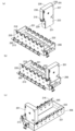
- 2 is a perspective view of the separating portion of the medicine packaging separating device of FIG. 1, observed from the discharge side of the medicine packaging strip.
- FIG. 2 is a perspective view of the separating portion of the medicine packaging separating device of FIG. 1, observed from the entrance side of the medicine packaging strip.
- FIG. 2A and 2B are diagrams showing the mechanism of the separating unit of the medicine packaging separating device of FIG. 1, in which FIG.
- FIG. 2A shows a state in which the upper and lower contact piece pairs are separated
- FIG. 2B shows a state in which the upper and lower contact piece pairs are brought together.
- FIG. 2 is a mechanism diagram of a discharge device of the medicine packaging and separating device of FIG. 1 .
- 13A and 13B are perspective views of a pair of upper and lower contact pieces.
- FIG. 1A is a plan view of the upper contact piece pair and its AA end view, where (a) shows a state in which the distance between the contact pieces is narrow, and (b) shows a state in which the distance between the contact pieces is wide.
- FIG. FIG. 4 is an exploded perspective view of the upper contact piece pair.
- 1A is an exploded perspective view of the contact piece
- 1B is a cross-sectional view of a main body portion of the contact piece.
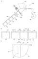
- This is an explanatory diagram showing the first and second stages when the drug packaging strip is separated, in which the center is a front view showing the state of the upper and lower abutment piece pairs, the left figure shows the state of the drug packaging strip at that time, and the right figure is a plan view showing the state of the upper and lower abutment piece pairs at that time.
- FIG. 13 is an explanatory diagram for explaining a method for positioning the medicine packaging strip.
- 1A is an explanatory diagram showing the main parts of a medicine packaging device
- FIG. 1B is a front view of a medicine packaging strip and medicine packages
- FIG. 1C is an enlarged view of a part of the medicine packaging strip.
- FIG. 11 is a perspective view of a medicine packaging separating device according to another embodiment of the present invention.
- FIG. 19 is a perspective view of the medicine packaging and separating device of FIG. 18, showing a state in which the upper drawer and the lower drawer are pulled out.
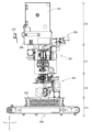
- FIG. FIG. 20 is a front view showing the internal structure of the medicine dispensing device of FIG. 18.
- FIG. 20 is a side view showing the internal structure of the medicine dispensing device of FIG. 18.
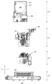
- 19 is a front view showing the internal structure of the medicine dispensing device of FIG. 18 separated into a cassette storage area, a separation area, and a distribution area.
- 19 is a side view showing the internal structure of the medicine dispensing device of FIG. 18 separated into a cassette storage area, a separation area, and a distribution area.
- FIG. 20 is a perspective view showing the internal structure of the medicine dispensing device of FIG. 18.
- FIG. 20 is a perspective view conceptually showing the internal structure of the medicine dispensing device of FIG. 18, illustrating the mechanism and arrangement of the main components.
- 1A is an oblique view of the cassette storage area with the cassette tray and roll cassette separated
- FIG. 1B is an oblique view of the cassette tray with the roll cassette attached, viewed from one direction
- FIG. 1C is an oblique view of the cassette tray with the roll cassette attached, viewed from the opposite side to FIG. 1B.
- FIG. 2 is a perspective view of a roll cassette and a drive device that drives the roll cassette.
- FIG. 1 is a front view showing the path of the drug packaging strip within the roll cassette.
- This is an oblique view showing the state when the drug packaging strip passes through a pair of straightening rollers, where (a) shows the state where the leading end of the drug packaging strip is near the pair of straightening rollers, and (b) shows the state where the leading end of the drug packaging strip is sandwiched between the pair of straightening rollers.
- 1 is a front view showing a state in which the leading end of the medicine packaging strip is caught between a pair of straightening rollers.
- FIG. 20 is a perspective view of the medicine dispensing device of FIG. 18 in a separated state from the separation area and the distribution area.
- FIG. 20 is a perspective view conceptually illustrating a dispensing area of the medicine dispensing device of FIG. 18.
- FIG. 20 is an exploded perspective view conceptually showing a multi-function block in the distribution area of the medicine dispensing device of FIG. 18.
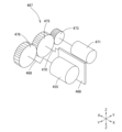
- FIG. 36 is a mechanism diagram of the dispensing section of the multifunction block of FIG. 35 .
- 5A and 5B are explanatory diagrams illustrating the coordinated operation of the take-up unit and the delivery unit, where (a) is a front view and a side view of the first stage, and (b) is a front view and a side view of the second stage.
- 10A and 10B are explanatory diagrams illustrating the coordinated operation of the take-up unit and the dispensing unit, where (c) is a front view and a side view of the third stage, and (d) is a front view and a side view of the fourth stage.
- 13A and 13B are explanatory diagrams illustrating the coordinated operation of the take-up unit and the dispensing unit, where (e) is a front view and a side view of the fifth stage, and (f) is a front view and a side view of the sixth stage.
- 1A is a perspective view showing a state in which the distribution box and the medicine setting device are separated
- FIG. 1B is a perspective view showing a state in which the medicine setting device is attached to the distribution box.
- the medicine packaging and separating device 1 of the present embodiment is used alone or incorporated into other equipment. 2 and 3, the medicine packaging separation device 1 is composed of a feed device 2, a separation section 3, and a discharge device 5. Each of these will be described below individually.
- the feed device 2 is composed of a transport path member 10 and a feed mechanism 11 .
- the transport path member 10 is a metal plate, and serves as a platform on which the medicine packaging strip 120 is placed and slid.
- the feed mechanism 11 is composed of a transport mechanism section 12 and a pressing section 15 .
- the transport mechanism 12 has a pair of upper and lower transport belts 16a, 16b, and moves the drug packaging strip 120 by sandwiching one side of the drug packaging strip 120 between the transport belts 16a, 16b.
- the conveyor belts 16a, 16b are each suspended around a pair of pulleys 17a, 17b and a pair of pulleys 18a, 18b.
- Tension pulleys 13a, 13b (not shown in FIG. 4) are provided outside the suspension paths of the conveyor belts 16a, 16b.
- the conveying mechanism 12 moves the drug packaging strip 120 by sandwiching one side of the drug packaging strip 120 between a conveying belt 16a suspended on a pair of pulleys 17a, 17b and a conveying belt 16b suspended on a pair of pulleys 18a, 18b.
- the pressing portion 15 has a pair of upper and lower rollers 26a, 26b.
- the lower roller 26a rotates by power, while the upper roller 26b rotates freely and is pressed against the lower roller 26a by a spring 27.
- the feed mechanism 11 has a geared motor 20 disposed at the bottom of the transport path member 10, and the rotational force of the geared motor 20 drives the transport belts 16a, 16b and the roller 26a on the lower side of the pressing portion 15.
- the rotational force of the geared motor 20 is transmitted to a gear train 23 consisting of gears 21a and 21b.
- the rotational force of one gear 21a of the gear train 23 is transmitted to a roller 26a on the lower side of the pressing unit 15.
- the rotational force of the gear 21a is also transmitted to the conveyor belts 16a and 16b via a gear train 22. That is, the rotational force of the gear 21 a is directly transmitted to the roller 26 a on the lower side of the pressing portion 15 .
- power is transmitted to the conveyor belts 16a and 16b via a gear train 22 consisting of gears 28a, 28b, and 28c. That is, the torque is transmitted to the lower pulley 18b from the gear 28c of the gear train 22.
- the torque of the pulley 18a is also transmitted to the upper pulley 17a via the gear train 25 consisting of the gears 24a and 24b. Therefore, when the geared motor 20 is driven, the lower surface of the upper conveyor belt 16a and the upper surface of the lower conveyor belt 16b move in the same direction.
- the feed device 2 is arranged so that the transport path members 10 are in a substantially parallel position, and the feed mechanism 11 is disposed on one side of the transport path members 10.
- the pressing unit 15 is provided at the most downstream position.
- the feeding device 2 is a device that feeds the medicine packaging strip 120 toward the separation section 3.
- the medicine packaging strip 120 is placed on the transport path member 10, and the common seal portion 125 of the medicine packaging strip 120 is sandwiched between a pair of upper and lower conveyor belts 16a, 16b.
- the geared motor 20 is driven to run the conveyor belts 16a, 16b, and the medicine packaging strip 120 sandwiched between them is fed toward the separation section 3 as the conveyor belts 16a, 16b run.
- the drug packaging strip 120 is fed in an amount corresponding to one drug package 110 .
- the separation section 3 is a section where the drug package 110 is separated from the drug package band 120 .
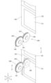
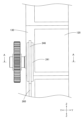
- the separation section 3 is composed of a pair of one-side contact pieces 30, a pair of other-side contact pieces 31, and a lifting mechanism 32 for lifting these.
- the drug packaging band 120 is transported horizontally, and the one-side abutment piece pair 30 is located at the upper part of the drug packaging band 120, so in the following description, the one-side abutment piece pair 30 will be referred to as the upper-side abutment piece pair 30.
- the other-side abutment piece pair 31 will be referred to as the lower-side abutment piece pair 31.
- the upper contact piece pair 30 is composed of a right contact piece 35, a left contact piece 36, a protruding piece 40 and a base 37.
- the base 37 has a common shaft 38 to which the right contact piece 35 and the left contact piece 36 are attached so as to be able to swing.
- the protruding piece 40 is provided between the right contact piece 35 and the left contact piece 36 and at one end in the longitudinal direction. It is desirable to change the position and length of the protruding piece 40 as appropriate depending on the width of the medicine packaging strip 120, etc.
- the right and left contact pieces 35 and 36 are the same except for being symmetrical, so the right contact piece 35 will be described in detail below.
- the right contact piece 35 is composed of a swing piece 41 and a plurality of thick members 42 . 12 and 13, the rocking piece 41 has a main body 43, and a plurality of attachment portions 45 are provided on one surface of the main body 43.
- the main body 43 is a long and thin bar-shaped portion.
- the cross-sectional shape of the main body 43 is as shown in FIG. 13( b ), and has an outer wall surface 56 , an inner wall surface 57 opposing the outer wall surface 56 , a top wall surface 68 , and an attachment portion arrangement surface 58 .
- the above-mentioned mounting portions 45 are formed on the mounting portion arrangement surface 58. As shown in Fig. 12, the mounting portions 45 are arranged in a straight line on one side of the main body portion 43. The mounting portions 45 are provided with a through hole 46 through which the common shaft 38 is inserted.
- the thickness member 42 is a rectangular thin plate and is attached to the inner wall surface 57 of the main body 43 by screws (not shown). 11 and 13, the main body 43 is divided into four areas in the longitudinal direction, and the number of the thickness members 42 varies depending on the area. Also, in this embodiment, the main body 43 itself has a different thickness depending on the area. That is, the second area has a large number of the thickness members 42, and the number of the thickness members 42 stacked decreases as the area progresses. The first area is irregular, and the number of the thickness members 42 is small in order to secure a space for the protruding pieces 40, as described later.
- the base portion 37 has a plate-shaped base body 48, and shaft support portions 50a, 50b are provided at both ends in the longitudinal direction of the base body 48.
- the common shaft 38 is supported by the shaft support portions 50a, 50b.
- the protruding piece 40 is provided on the common shaft 38 and is a plate-like member made of a hard material such as metal.
- the protruding piece 40 is a thin plate that is approximately trapezoidal in front view and has a pointed tip. That is, the protruding piece 40 has a vertical line 90 and an inclined line 91 that is connected to the vertical line 90, and the intersection of the vertical line 90 and the inclined line 91 is sharp at an acute angle.
- the thickness of the protruding piece 40 is uniform, but the inclined line 91 may be blade-shaped.
- each side of the protruding piece 40 is linear, but may be arc-shaped.
- the common shaft 38 is inserted through the through holes 46 in the mounting portions 45 of the right abutment piece 35 and the left abutment piece 36.
- the right abutment piece 35 and the left abutment piece 36 can swing relative to the common shaft 38.
- the right abutment piece 35 and the left abutment piece 36 are biased in a direction to approach each other by a spring (elastic member) 47.
- the right abutment piece 35 and the left abutment piece 36 do not approach each other beyond a certain limit.
- the state in which the right contact piece 35 and the left contact piece 36 are attached to the base portion 37 is as shown in FIGS. 9, 10 and 11, and the thickness members 42 of the right contact piece 35 and the left contact piece 36 are positioned opposite each other.
- the main body 43 of the right contact piece 35 and the left contact piece 36 is divided into four areas in the longitudinal direction, and the number of overlapping thick members 42 decreases as the area numbers from the second area onwards progress.
- the right contact piece 35 and the left contact piece 36 are biased in a direction in which they approach each other by the spring (elastic member) 47. Therefore, as shown in Fig.
- the distance between the right contact piece 35 and the left contact piece 36 is narrow, and in an area where the number of thick members 42 is small, the distance between the right contact piece 35 and the left contact piece 36 is wide.
- the interval in the second area is the narrowest, and the interval in the fourth area is the widest.
- the thickness of the main body 43 of the oscillating piece 41 varies from area to area, and the number of thickness members 42 also varies.
- the distance between the right abutment piece 35 and the left abutment piece 36 varies depending on the area by changing both the thickness of the main body 43 and the number of thickness members 42, but the distance between the right abutment piece 35 and the left abutment piece 36 may also be made to vary depending on the area simply by changing the thickness of the main body 43.
- the distance between the right abutment piece 35 and the left abutment piece 36 may also be made to vary depending on the area simply by changing the number of thickness members 42.
- one surface of the right contact piece 35 and the entire surface of the left contact piece 36 serve as contact portions 51 a, 51 b that come into contact with the medicine packaging strip 120. That is, the top wall surface 68 of the oscillating piece 41 of the right-side contact piece 35 and the side surfaces of the plurality of thickness members 42 function as a contact portion 51a that contacts the drug packaging band 120 of the right-side contact piece 35. Similarly, the top wall surface 68 of the oscillating piece 41 of the left-side contact piece 36 and the side surfaces of the plurality of thickness members 42 function as a contact portion 51b that contacts the drug packaging band 120 of the left-side contact piece 36.
- the contact portions 51a, 51b are generally inclined inwardly.
- the right contact piece 35 and the left contact piece 36 swing around the common shaft 38.
- the straight line Z is inclined with respect to the perpendicular line Y.
- the left and right contact portions 51a, 51b are offset from each other with respect to the perpendicular line Y that passes through the center of the common shaft 38.
- a protruding piece 40 is fixed between the right contact piece 35 and the left contact piece 36.
- the protruding piece 40 is provided in a first area where the distance between the right contact piece 35 and the left contact piece 36 is narrow. In the first area, like the second area, the distance between the contact portions 51a, 51b is narrow, and by interposing the protruding piece 40, there is almost no gap when the contact portions 51a, 51b are closed.
- the protruding piece 40 is located between the pair of contact portions 51a, 51b.
- the contact portions 51a, 51b have a length at least equivalent to the width of the drug packaging strip 120, and the protruding piece 40 is located near the ends of the contact portions 51a, 51b.
- the lower abutment pair 31 is the same as the upper abutment pair 30 described above except that it does not have the protruding piece 40, so only a brief description will be given.
- the components of the lower abutment pair 31 are marked with "'". Note that, for illustration purposes, some of the components of the lower abutment pair 31 are not shown. Components that are not shown are marked with parentheses, such as (42').
- the lower contact piece pair 31 has a right contact piece 35' and a left contact piece 36' which are attached to a common shaft 38' of a base portion 37' so as to be able to swing.
- the right abutment piece 35' and the left abutment piece 36' are identical except that they are symmetrical.
- the right contact piece 35' is configured by attaching a thickness member (42') to a swing piece 41'.
- the swing piece 41' has a main body portion (43') and a plurality of mounting portions (45').
- the main body portion (43') is divided into four areas in the longitudinal direction.
- the second area has a large number of thickness members 42, and the number of layers decreases as the area progresses.
- the right contact piece 35' and the left contact piece 36' are pivotable about a common shaft 38'.
- a spring (47) biases the right contact piece 35' and the left contact piece 36' in a direction in which they approach each other.
- the thickness members (42') of the right contact piece 35' and the left contact piece 36' are located opposite each other.
- the entire surface of the right contact piece 35' and the entire surface of the left contact piece 36' form contact portions 51'a, 51'b that contact the drug packaging strip 120.
- the right abutment piece 35, 35' and the left abutment piece 36, 36' rotate to change position, opening up the gap between the right abutment piece 35, 35' and the left abutment piece 36, 36', but the structure may also be such that the right abutment piece 35, 35' and the left abutment piece 36, 36' move horizontally to open up the gap between them.
- the oscillating piece 41 used in this embodiment has a thickness member 42, and the number of thickness members 42 is varied depending on the location to make the distance between the right-side abutment piece 35 and the left-side abutment piece 36 different depending on the location, but the distance between the right-side abutment piece 35 and the left-side abutment piece 36 may also be changed by changing the thickness of the thickness member 42 itself. Moreover, the distance between the right contact piece 35 and the left contact piece 36 may be changed by changing the thickness of the swing piece 41 itself.
- the thickness members 4 are overlapped to provide an anti-slip effect when they come into contact with the medicine packaging strip 120 . If the thick member 4 is not used, it is recommended to roughen the tip of the contact portion 51 to provide an anti-slip treatment.
- the lifting mechanism 32 moves the upper contact piece pair 30 and the lower contact piece pair 31 in the vertical direction to move them closer to or away from each other.
- the lifting mechanism 32 is a pressing means that presses the upper contact piece pair 30 and the lower contact piece pair 31 against the drug packaging band 120.
- the lifting mechanism 32 has one geared motor 52 and a link mechanism, and by rotating the geared motor 52, the upper contact piece pair 30 and the lower contact piece pair 31 are lifted and lowered.
- the mechanical portion of the lifting mechanism 32 is as shown in FIG. 7, and has a crank portion 61 on the lower side and a lever member 62 on the upper side, and the crank portion 61 and the lever member 62 are linked by an interlocking member 63.
- the lifting mechanism 32 has a pair of guide poles 60, and the upper contact piece pair 30 and the lower contact piece pair 31 are attached to the guide pole 60 via holding members 65, 66, respectively, so that they can be raised and lowered. That is, the holding members 65, 66 each have a linear bearing 67, which engages with the guide pole 60.
- the upper contact piece pair 30 is fixed to the holding member 65
- the lower contact piece pair 31 is fixed to the holding member 66.
- the interlocking member 63 is a part of the lower holding member 66 and is a plate-shaped member.
- the crank portion 61 is provided between the geared motor 52 and a lower holding member 65 .
- the lever member 62 is provided between the interlocking member 63 and the upper holding member 65 .
- the intermediate portion 95 of the lever member 62 is supported by the bearing 70 so as to be able to swing on a fixed portion (not shown). Therefore, the force application side 80 and the action point 81 side of the lever member 62 swing about the intermediate portion 95. That is, when the force application side 80 rises, the action point 81 descends, and when the force application side 80 descends, the action point 81 rises.
- the force application side 80 of the lever member 62 is connected to the interlocking member 63.
- the action point 81 side of the lever member 62 is connected to the upper holding member 65.
- the connection portion between the action point 81 side of the lever member 62 and the interlocking member 63 is rotatable and has a degree of freedom in the lateral direction.
- the connection portion between the action point 81 side of the lever member 62 and the upper holding member 65 is also rotatable and has a degree of freedom in the lateral direction.
- the crank portion 61 provided on the lower side and the lever member 62 provided on the upper side are out of phase with each other.
- the interlocking member 63 is a part of the lower holding member 66, and the two are joined together. Therefore, when the lower holding member 66 moves up and down, the interlocking member 63 also moves up and down.
- the crank portion 61 is provided between the geared motor 52 and the lower holding member 66, and when the crank portion 61 is rotated by the geared motor 52, the rotational motion of the geared motor 52 is converted into linear motion by the crank portion 61, and the lower holding member 66 rises and falls along the guide pole 60.
- the interlocking member 63 integrated with the holding member 66 also rises and falls, and the force point side 80 of the lever member 62 rises and falls.
- the action point 81 side of the lever member 62 falls, and the upper holding member 65 falls.
- the lifting mechanism 32 of this embodiment uses a crank portion 61 and a lever member 62 that are out of phase with each other, and by rotating one geared motor 52, the upper abutment piece pair 30 and the lower abutment piece pair 31 are raised and lowered in opposite directions.
- the present invention is not limited to this configuration, and the upper contact piece pair 30 and the lower contact piece pair 31 may be raised and lowered by separate motors. Also, mechanisms other than a crank or lever may be used.
- the discharge device 5 is composed of a transport path member 53 and a feed mechanism 72, as shown in FIGS.
- the transport path member 53 is a metal plate, and serves as a platform on which the medicine packaging strip 120 is placed and slid.
- the feed mechanism 72 includes a discharge roller 71 and a conveying mechanism 73 formed by a belt. The upper surface of the discharge roller 71 comes into contact with the medicine packaging strip 120 and moves the medicine packaging strip 120 .
- the basic configuration of the conveying mechanism 73 of the discharge device 5 is the same as that of the conveying mechanism 12 of the feeding device 2 described above, and has a pair of upper and lower conveying belts 75a, 75b, and moves the drug packaging band 120 by sandwiching one side of the drug packaging band 120 between the conveying belts 75a, 75b.
- the conveyor belts 75a, 75b are each suspended around a pair of pulleys 77a, 77b and a pair of pulleys 78a, 78b.
- Tension pulleys 76a, 76b are provided outside the suspension paths of the conveyor belts 75a, 75b (not shown in FIG. 8).
- the conveying mechanism 73 moves the drug packaging strip 120 by sandwiching one side of the drug packaging strip 120 between a conveying belt 75a suspended on a pair of pulleys 77a, 77b and a conveying belt 75b suspended on a pair of pulleys 78a, 78b.
- the feed mechanism 72 has a geared motor 85 at its upper part, and the rotational force of the geared motor 85 is transmitted to a gear train 88 consisting of gears 87a and 87b by a belt 86.
- the rotational force of the upper gear 87a of the gear train 88 is transmitted to the pulley 77a, causing the upper conveyor belt 75a to run.
- the rotational force of the lower gear 87b of the gear train 88 is transmitted to the pulley 78a, causing the lower conveyor belt 75b to run. Furthermore, the rotational force of the gear 87 b on the lower side is transmitted to the discharge roller 71 . Therefore, when the geared motor 85 is driven, the lower surface of the upper conveyor belt 75a and the upper surface of the lower conveyor belt 75b move in the same direction. The upper surface of the discharge roller 71 also rotates in the same direction.
- the medicine packaging separation device 1 is composed of the feeding device 2, the separation section 3, and the discharge device 5, which are arranged in this order. That is, the feeding device 2 is located upstream of the separation section 3, and the discharge device 5 is located downstream of the separation section 3.
- the conveyor belts 16a, 16b of the feeding device 2 and the conveyor belts 75a, 75b of the discharge device 5 are both located at the rear side in Figures 1 and 2.
- the first areas of the upper contact piece pair 30 and the lower contact piece pair 31 are located at the rear side in Figures 1 and 2.
- the conveyor belts 16a, 16b of the feed device 2 a part of the first area of the upper contact piece pair 30 and the lower contact piece pair 31, and the conveyor belts 75a, 75b of the discharge device 5 are aligned in a straight line.
- the protruding piece 40 is provided in the first area.
- the distance between the right contact piece 35 and the left contact piece 36 is narrow, and the distance becomes wider as the area number increases.
- the distance between the right abutment piece 35 and the left abutment piece 36 is narrow near the area on the extension of the conveying belts 16a, 16b of the feed device 2, and the distance between the right abutment piece 35 and the left abutment piece 36 becomes narrower and wider as it moves away from the extension line of the conveying belts 16a, 16b.
- the discharge device 5 is provided with an edge sensor 92 ( Figure 16).
- the edge sensor 92 detects the leading edge of the drug packaging strip 120.
- a photoelectric sensor is used as the edge sensor 92.
- the medicine packaging strip 120 is introduced from the feeder 2 and sent to the separation section 3. At this time, the upper contact piece pair 30 and the lower contact piece pair 31 are separated from each other.
- the drug packaging strip 120 is fed frame-by-frame with the common seal portion 125 sandwiched between a pair of upper and lower conveyor belts 16a, 16b and enters the cutting section 3, and stops when the joining area 122 of the drug packaging strip 120 reaches the cut section between the upper side abutment piece pair 30 and the lower side abutment piece pair 31.
- the edge sensor 92 is installed at a position that is one packet's worth of drug packaging 110 away from the cutting section. Then, the drug packaging strip 120 is moved from left to right in Fig. 16, and when the edge sensor 92 detects the leading edge as shown in Fig. 16(a), the feeding of the drug packaging strip 120 is stopped. As a result, the joint area 122 of the drug packaging strip 120 stops between the upper contact piece pair 30 and the lower contact piece pair 31 .
- the upper abutment piece pair 30 and the lower abutment piece pair 31 both have a right abutment piece 35 and a left abutment piece 36, and the boundary line between the right abutment pieces 35, 35' and the left abutment pieces 36, 36' is positioned so that it coincides in plan with the perforation 126 of the drug packaging strip 120.
- the geared motor 52 of the cutting section 3 is driven to raise and lower the upper abutment piece pair 30 and the lower abutment piece pair 31 so that the upper abutment piece pair 30 and the lower abutment piece pair 31 come into contact with the drug packaging band 120. That is, as in the second stage of Figure 14, the upper abutment piece pair 30 is lowered to bring the upper abutment piece pair 30 into contact with the front of the drug packaging strip 120, and the lower abutment piece pair 31 is raised to bring the lower abutment piece pair 31 into contact with the back of the drug packaging strip 120.
- the right abutment piece 35 of the upper abutment piece pair 30 abuts against the right side (the feed device 2 side) of the perforation 126 of the drug packaging strip 120
- the left abutment piece 36 of the upper abutment piece pair 30 abuts against the left side (the discharge device 5 side) of the perforation 126 of the drug packaging strip 120.
- the right abutment piece 35' of the lower abutment piece pair 31 abuts against the right side (the feed device 2 side) of the perforation 126 of the drug packaging strip 120
- the left abutment piece 36' of the upper abutment piece pair 30 abuts against the left side (the discharge device 5 side) of the perforation 126 of the drug packaging strip 120. Therefore, the upper and lower right contact pieces 35, 35' hold the right side (the side of the feeding device 2) of the perforation 126 of the medicine packaging strip 120.
- the upper and lower left contact pieces 36, 36' hold the left side (the side of the discharge device 5) of the perforation 126 of the medicine packaging strip 120.
- the tip of the protruding piece 40 of the upper contact piece pair 30 biases the drug packaging strip 120 to create a cut.
- the tip of the protruding piece 40 scratches the end of the perforation 126 of the drug packaging strip 120. That is, the tip of the protruding piece 40 presses against the perforation 126 in the vicinity of the common seal portion 125 in the storage portion 121, scratches it, and creates a cut. Since the perforation 126 is present in that portion and the tip of the protruding piece 40 is sharp, the protruding piece 40 can be easily torn.
- the geared motor 52 of the separating section 3 further rotates, so that the upper contact piece pair 30 and the lower contact piece pair 31 press against each other.
- the right contact piece 35 and the left contact piece 36 of the upper contact piece pair 30 are pivotable about the common shaft 38, and the contact portions 51a, 51b are offset from a perpendicular line Y passing through the center of the common shaft 38.
- the contact portions 51a, 51b are generally inclined inward.
- the right contact piece 35' and the left contact piece 36' of the lower contact piece pair 31 are also capable of swinging about the common shaft 38', and the contact portions 51'a, 51'b are offset from the perpendicular line Y passing through the center of the common shaft 38.
- the contact portions 51'a, 51'b are generally inclined inward.
- the upper contact piece pair 30 and the lower contact piece pair 31 are pressed against each other, so that the right contact pieces 35, 35' and the left contact pieces 36, 36' rotate and change their posture as shown in the third stage of Fig. 15, and the distance between the contact parts 51a, 51b and the distance between the contact parts 51'a, 51'b increase while holding both ends of the perforation 126. Therefore, while both sides of the perforation 126 are held, they are pulled left and right, and the perforation 126 tears. Protruding piece 40 is pushed even deeper into the packaging paper.
- protruding piece 40 has inclined line 91 that connects to straight line 90, when protruding piece 40 is pushed even deeper, it becomes susceptible to tearing (creating a cut) to the left and right starting from the length of inclined line 91, and the cut continuing to perforation 126 extends toward common seal portion 125, creating a cut that reaches seal portion 130.
- the main body 43 of the right contact piece 35 and the left contact piece 36 is divided into four areas in the longitudinal direction, with the second area having the narrowest spacing and the fourth area having the widest spacing.
- the spacing is narrow on the common seal portion 125 side and wide on the bottom side of the bag (the fold side of the packaging paper).
- the bottom side of the bag is pulled more strongly left and right, and the perforation 126 tears from the bottom side of the bag.
- the protruding piece 40 pierces the vicinity of the upper contact piece pair 30, creating a cut in the common seal portion 125. After being cut away sequentially from the perforation on the bottom side (the fold side of the packaging paper), both sides of the protruding piece 40 are pulled apart. Therefore, as the upper contact piece pair 30 and the lower contact piece pair 31 approach each other, all of the perforations 126 are cut, and the common seal portion 125 is also cut off.
- the separated drug packaging 110 is discharged to the outside by the discharge device 5.
- the geared motor 52 of the separating section 3 is driven, the upper contact piece pair 30 and the lower contact piece pair 31 are separated from each other, and a new drug package 110 is transported from the feed device 2 to the separating section 3 and separated.
- an edge sensor 92 is installed at the exit side of the cutting unit 3, at a position spaced from the cutting unit 3 by the width of one pharmaceutical package 110, and the edge sensor 92 monitors the presence or absence of the pharmaceutical package strip 120.
- a tearing operation is performed while the edge sensor 92 detects (turns on) the pharmaceutical package strip 120, and when the pharmaceutical package strip 120 is torn by the upper contact piece pair 30 and the lower contact piece pair 31, the pharmaceutical package 110 cut off by the discharge device 5 is discharged to the outside. That is, the conveyor belts 75a, 75b and rollers 71 of the discharge device 5 rotate, and the pharmaceutical package 110 on the cut side is discharged.
- the edge sensor 92 turns off, as shown in FIG. 16(b). If the edge sensor 92 remains on, an error is reported as the separation of the medication package 110 was not successful.
- the above-mentioned first to fourth steps are repeated in sequence, and the drug packaging strip 120 is cut into drug packages 110. That is, when the first drug package 110 is normally separated and discharged to the outside, the edge sensor 92 turns off. At that point, the feeding of the drug packaging strip 120 remaining upstream is resumed, and when the leading edge of the next drug package 110 reaches the position of the edge sensor 92 and the edge sensor 92 turns on, the feeding of the drug packaging strip 120 stops (first stage). At this time, since the tear-off portion 3 is located near the perforation 126 between the next packet and the packet after that, the drug packaging strip 120 is torn by the upper contact piece pair 30 and the lower contact piece pair 31 in the same manner as described above (second to fourth stages).
- the mechanism of the drug packaging separation device 1 of this embodiment is mainly to separate adjacent drug packages 110 on the drug packaging strip 120 and tear the space between them. That is, the mechanism of the drug packaging separation device 1 of this embodiment is a mechanism that separates adjacent drug packages 110, rather than cutting by inserting a blade aimed at the perforations 126 of the drug packaging strip 120. Therefore, in the drug packaging separation device 1 of this embodiment, it is sufficient to position the drug packaging strip 120 so that the abutment portions 51a and 51b are located on either side of the perforation 126, and there is an advantage that high positioning accuracy is not required.
- the length of the drug packaging 110 varies depending on the amount of drug contained in the prescription, such as 80 mm, 70 mm, 60 mm, etc., but in the drug packaging separation device 1 of this embodiment, after the previous drug packaging 110 is separated, when the leading edge of the next drug packaging 110 reaches the position of the edge sensor 92 and the edge sensor 92 turns on, the feeding of the drug packaging strip 120 stops, so the distance between the edge sensor 92 and the separation unit 3 is set in principle to be the same as the length of the drug packaging 110.
- the position of the edge sensor 92 is fixed, but multiple edge sensors 92 may be provided depending on the length of the drug packaging 110, or the edge sensor 92 may be made movable so that the edge sensor 92 can be moved to a position depending on the length of the drug packaging 110.
- the medicine packaging separation device 1 of the embodiment described above has upper and lower contact piece pairs 30, 31, and the upper and lower contact piece pairs 30, 31 move to clamp the medicine packaging strip 120.
- the present invention is not limited to this configuration, and only one of the contact piece pairs may move to clamp the medicine packaging strip 120.
- the medicine packages 110 can be separated by pressing only one contact piece pair against the medicine packaging strip 120.
- the perforations 126 do not reach the common seal portion 125, and the common seal portion 125 is a seal portion 130 where there is no tear line.
- the drug packaging separation device of the present invention can be used not only for drug packaging strips 120 in which the perforations 126 end halfway as described above, but also for drug packaging strips in which the perforations 126 are formed to the full width of the drug packaging strip 120.
- a cut is made in the drug packaging strip 120 by the protruding piece 40 on the upper contact piece pair 30.
- the protruding piece 40 is not essential, and may be omitted.
- the protruding piece 40 is present, so that the distance between the right contact piece 35 and the left contact piece 36 in the second area is narrowest, but in the absence of the protruding piece 40, it is desirable to make the distance between the right contact piece 35 and the left contact piece 36 in the first area narrowest.
- the drug packaging strip 120 is transported horizontally and sandwiched between the upper abutment piece pair 30 and the lower abutment piece pair 31 to tear the drug packaging strip 120 to the upstream and downstream sides, but the transport direction of the drug packaging strip 120 may be diagonal or vertical.
- the drug packaging strip 120 may be moved vertically to hang down the drug packaging strip 120, and the front and back sides of the drug packaging strip 120 may be sandwiched between the one-side abutment piece pair 30 and the other-side abutment piece pair 31 to tear the drug packaging strip 120.
- the drug packaging separation device 1 described above is a drug packaging separation device that separates individual drug packages from a drug packaging band in which drug packages are connected in a band shape, and is characterized in that it has a pair of contact parts that contact the same surface of the drug packaging band and a protruding piece, and when the contact parts are in contact with the drug packaging band, the distance between the contact parts widens to bias the drug packages in a direction to separate them, and the protruding piece cuts a portion of the drug packaging band.
- the drug packaging separation device of this embodiment has a pair of abutting parts that contact the same surface of the drug packaging strip. Although not limited thereto, it is preferable that the pair of abutting parts are set so as to contact the same surface of the drug packaging strip across the perforation of the drug packaging strip.
- the abutting parts widen the distance between the abutting parts when they are in contact with the drug packaging strip. Therefore, the drug packaging strip is biased in a direction to separate the drug packaging. As a result, the drug packaging strip is pulled left and right across the perforation and torn off from the perforation.
- the drug packaging separation device of this embodiment has a protruding piece that forms a cut in part of the drug packaging strip. Therefore, even if there is a sealed portion without a perforation, the cut formed by the protruding piece will be used as a starting point to cut and separate the drug packaging from the drug packaging strip.
- the medicine packaging separater 200 of the second embodiment operates three-dimensionally, the X-axis, Y-axis, and Z-axis may be used in the description.
- the left-right direction is the X-axis
- the depth direction is the Y-axis
- the height direction is the Z-axis.
- the drug packaging separation device 200 of the second embodiment incorporates the separation unit 3 of the first embodiment.
- the drug packaging separation device 200 of this embodiment has a configuration in which the separation unit 3 is installed horizontally (XY plane) as shown in Figure 33, and the drug packaging strip 120 is moved vertically (Z-axis direction) as shown in Figures 30 and 31 to hang down the drug packaging strip 120, and the front side and back side of the drug packaging strip 120 are sandwiched between a pair of one-side contact pieces 30 and a pair of other-side contact pieces 31 to tear the drug packaging strip 120.
- the drug packaging separation device 200 can also be equipped with a plurality of roll cassettes 201 for storing drug packaging strips 120, and supplies the drug packaging strip 120 from a selected roll cassette 201 to the separation section 3, where the drug packages 110 are separated from the drug packaging strip 120. Furthermore, in the second embodiment of the drug packaging separation device 200, a distribution box 202 can be installed at the bottom (below in the Z-axis direction) and the separated drug packages 110 can be inserted into a specified compartment 203 of the distribution box 202.
- the external appearance of the medicine packaging and separating device 200 of this embodiment is as shown in Figures 18 and 19, and is covered with a vertical rectangular outer shell 205.
- a vertical rectangular outer shell 205 On the upper side of the side of the outer shell 205, as shown in Figure 19, an upper door 208 for inserting and removing a cassette tray 206 is provided. 19, a lower door 207 for inserting and removing the distribution box 202 is provided on the lower side of the front of the outer shell 205.
- the drug packaging separation device 200 has a cassette storage area 210, a separation area 211, a distribution area 212, and a distribution box installation area 213. Each will be described individually below.
- the cassette housing area 210 is a portion where a plurality of roll cassettes 201 are placed via cassette trays 206 . 24, 26(a) and 26(b), the cassette housing area 210 has a pull-out rail 215, and a cassette tray 206 is installed on the pull-out rail 215.
- the cassette tray 206 moves linearly in the X-axis direction along the pull-out rail 215, and can be stored in the outer body 205 as shown in FIG. 18 or pulled out from the outer body 205 as shown in FIG.
- the structure of the drawer rail 215 is the same as that of a known sliding drawer rail, and therefore a detailed description thereof will be omitted.
- the cassette tray 206 is a container that is rectangular in plan view and has an open upper side.
- a plurality of notches 216 and holes 265 are provided on one side of the cassette tray 206.
- An engagement hook 220 is provided near the notch 216.
- a hole 221 is provided on the other side of the cassette tray 206.
- a plurality of through holes 222 are provided in the bottom of the cassette tray 206.
- the roll cassette 201 will be described with reference to FIGS.
- the roll cassette 201 accommodates a reel 160 on which a continuous drug packaging strip 120 that has been packaged by a packaging machine based on prescription information is wound in a roll shape, as shown in FIG.
- the roll cassette 201 employed in this embodiment has a function corresponding to the "feeding device 2" in the previous embodiment.
- the roll cassette 201 has a pair of straightening rollers 240, as described below, and has a function of straightening the medicine packaging strip 120 by sandwiching the sealed portion 130 of the medicine packaging strip 120 with the pair of straightening rollers 240 to form a crease therebetween, thereby straightening the medicine packaging strip 120.
- the roll cassette 201 has a thin case member 223 that is generally rectangular when viewed from the front.
- the case member 223 has a notch 225 formed in a lower corner based on the mounting posture.
- the case member 223 has a main body 230 having a rear wall 226 and a peripheral wall 227 based on the mounting posture, and a front wall 231 is provided on the front side.
- the front wall 231 is transparent and is attached to the main body 230 via a hinge 238. Therefore, the front wall 231 of the case member 223 can be opened and closed.
- a through hole 228 is provided in the side surface of the case member 223.
- a toggle-type engagement member 218 is provided above the cutout portion 225 of the case member 223, as shown in FIG.
- a reel mounting shaft 233 As shown in Figures 25, 27 and 29, a reel mounting shaft 233, a guide roller 237, a feed device 235 and a straightening roller pair 240 are provided within the case member 223. That is, a reel mounting shaft 233 is provided on the upper side of the case member 223 with reference to the mounting posture. The reel mounting shaft 233 protrudes in a cantilever shape from the rear wall 226 of the case member 223. The reel mounting shaft 233 is supported by a bearing (not shown) and is freely rotatable.
- a guide roller 237 is provided directly below the reel mounting shaft 233.
- the guide roller 237 is supported by a bearing (not shown) and can rotate freely.
- a feed device 235 is provided at the bottom of the case member 223.
- the feed device 235 is similar to the feed device 2 of the first embodiment, and as shown in FIG. 29, moves the drug packaging band 120 by sandwiching one side of the drug packaging band 120 between a conveyor belt 16a suspended on a pair of pulleys 17a, 17b and a conveyor belt 16b suspended on a pair of pulleys 18a, 18b.
- Tension pulleys 13a, 13b are provided outside the suspension path of the conveyor belts 16a, 16b (not shown in FIG. 25).
- a pair of straightening rollers 240 is provided below the feed device 235.
- the pair of straightening rollers 240 is composed of a convex roller 241 and a grooved roller 242, as shown in FIGS.
- the ridge roller 241 has an integrated meshing portion 243 and a holding portion 245, and the meshing portion 243 is provided on the base side.
- the meshing portion 243 is a thin roller and is provided with a ridge 246 on its periphery.
- the holding portion 245 has a considerable length.
- the ridge 246 has a rectangular cross-sectional shape.
- the grooved roller 242 has a recessed groove 247 formed on its periphery.
- the pair of pulleys 17a, 17b of the feed device 235 and the convex roller 241 of the straightening roller pair 240 are attached to a common movable plate 261 as shown in FIG. That is, the pair of pulleys 17a, 17b of the feed device 235 are pressed against the other pair of pulleys 18a, 18b. Also, the convex roller 241 of the straightening roller pair 240 is pressed against the grooved roller 242, and the protrusions 246 of the meshing portion 243 fit into the concave grooves 247 of the grooved roller 242.
- a power transmission shaft 250 is rotatably installed inside the case member 223 on the axis of a through hole 228 provided in the side surface of the case member 223.
- a clutch piece 251 is provided on one end of the power transmission shaft 250.
- a bevel gear 248 is attached to one end of the power transmission shaft 250.
- gear 252 is provided on the outside of the case member 223 of the through-hole transmission shaft 263.
- gears 253, 255, 256, and 257 are provided on the rear side of the case member 223.
- the gears 253 and 255 on the rear side drive the feed device 235 inside the case member 223 , with the gear 253 being connected to a pulley 18 b of the feed device 235 and the gear 255 being connected to a pulley 17 b of the feed device 235 .
- the gears 256 and 257 on the rear side drive the straightening roller pair 240 inside the case member 223, with the gear 256 being connected to the grooved roller 242 of the straightening roller pair 240 and the gear 257 being connected to the convex roller 241 of the straightening roller pair.
- the rotational force of the bevel gear 248 of the power transmission shaft 250 is transmitted to a gear 252 provided on the back side of the case member 223 via a bevel gear 258 provided on the through-hole transmission shaft 263 .
- the gear 252 also engages with the gear 253, which in turn engages with the gear 255. Therefore, when the gear 252 rotates, the gear 253 rotates and the pulley 18b of the feed device 235 rotates. Furthermore, the gear 255 rotates upon receiving power transmission from the gear 253, and the pulley 17b of the feed device 235 rotates. Therefore, when the power transmission shaft 250 rotates, the feed device 235 in the case member 223 is driven.
- gear 252 engages with gear 256, which in turn engages with gear 257. Therefore, when gear 252 rotates, gear 256 rotates and causes grooved roller 242 of straightening roller pair 240 to rotate. Gear 257 also rotates upon receiving power from gear 256, and causes convex roller 241 of straightening roller pair 240 to rotate. Therefore, when power transmission shaft 250 rotates, straightening roller pair 240 inside case member 223 is driven.
- a reel 160 on which the medicine packaging strip 120 is wound in a roll is attached to the roll cassette 201. That is, the front wall 231 is opened and the reel 160 is attached to the reel attachment shaft 233. Then, the end of the medicine packaging strip 120 is clamped by the feeding device 235. When the power transmission shaft 250 is rotated in this state, the medicine packaging strip 120 is fed downward.
- the drug packaging strip 120 discharged from the feed device 235 advances to a pair of downstream straightening rollers 240, and the sealed portion 130 of the drug packaging strip 120 is sandwiched between the meshing portion 243 of the convex roller 241 and the grooved roller 242, as shown in Figures 30 and 31.
- the meshing portion 243 has a circumferential protrusion 246, and the grooved roller 242 has a circumferential recess 247.
- the protrusion roller 241 is pressed towards the grooved roller 242, and the protrusion 246 of the meshing portion 243 fits into the recess 247 of the grooved roller 242.
- the sealed portion 130 of the drug packaging strip 120 is folded between the ridge 246 of the meshing portion 243 and the groove 247 of the grooved roller 242. Therefore, as shown in Figures 31 and 32(c), a continuous fold 260 is formed in the sealed portion 130 of the drug packaging strip 120 in the longitudinal direction.
- the straightening roller pair 240 of this embodiment is for straightening out any bends in the medicine packaging strip 120.
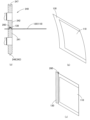
- the bends in the medicine packaging strip 120 are straightened out to give it a straight shape. That is, the medicine packaging strip 120 sent out from the reel 160 has a tendency to bend and curl as shown in Fig. 32(b).
- the medicine packaging strip 120 is straightened as shown in Fig. 32(c).
- the pharmaceutical wrapper strip 120 with the crease 260 is allowed to hang down out of the cassette tray 206 .
- a plurality of roll cassettes 201 are mounted on a cassette tray 206 as shown in FIG.
- a toggle-type engagement member 218 is provided on the side of the roll cassette 201
- an engagement hook 220 is provided on the cassette tray 206.
- the roll cassette 201 is inserted into the accommodation portion of the cassette tray 206, and the toggle-type engagement member 218 of the roll cassette 201 engages with the engagement hook 220 of the cassette tray 206 to fix the roll cassette 201 to the cassette tray 206.
- a number of photoelectric sensors 270 are installed in the cassette storage area 210, and the photoelectric sensors 270 monitor the inside of the cassette tray 206 through holes 265 in the cassette tray 206.
- the photoelectric sensors 270 confirm the presence or absence of the drug packaging strip 120. That is, information on which storage section of the cassette tray 206 the cassette tray 206 is in is detected, and transmitted to a control device (not shown). It is also possible to provide a sensor that confirms the presence or absence of the roll cassette 201.
- the separation area 211 is an area having functions corresponding to the separation unit 3 and the transport mechanism unit 73 of the first embodiment.
- the separation area 211 is also provided with a traverse function 217 for moving the separation unit 3 and the like to the position of the cassette tray 206 in the upper cassette housing area 210.
- the separation area 211 is equipped with a drive unit 300 for driving the cassette tray 206 as shown in Figure 33.
- a lateral block 301 is configured by integrating three components: an apparatus equivalent to the separation unit 3 in the first embodiment, a transport mechanism unit 73, and a drive unit 300 that drives the cassette tray 206.
- a lateral rail 310 is installed in the separation area 211, and the lateral block 301 moves horizontally along the lateral rail 310. That is, a travel motor 311 is attached to the lateral rail 310, and the lateral block 301 moves laterally by driving the travel motor 311.
- the lateral block 301 has a rectangular parallelepiped main body 302 and an overhanging portion 303 provided above the main body 302.
- the separating section 3 is installed in a horizontal position at the upper end of the main body section 302.
- the separating section 3 is composed of a one-side abutment piece pair 30, an other-side abutment piece pair 31, and a lifting mechanism 32 for lifting and lowering them. It also has an approach/separation mechanism (not shown) for moving the one-side abutment piece pair 30 and the other-side abutment piece pair 31 in the horizontal direction to bring them closer to and away from each other.
- the approach/separation mechanism (not shown) is substantially the same as the lifting mechanism 32 in the first embodiment, and is merely a modified version of the lifting mechanism 32. That is, it has a pair of guide poles 60 , a holding member 65 that holds the one-side abutment piece pair 30 , and a holding member 66 that holds the other-side abutment piece pair 31 .
- the discharge device includes a first conveying mechanism 73a and a second conveying mechanism 73b.
- the conveying mechanism 73a moves the medicine packaging strip 120 by sandwiching one side of the medicine packaging strip 120 between a conveying belt 75a suspended on a pair of pulleys 77a, 77b and a conveying belt 75b suspended on a pair of pulleys 78a, 78b.
- a tension pulley is provided on the outside of the suspension path of the conveying belts 75a, 75b.
- the second conveying mechanism 73b is also a similar mechanism, which moves the drug packaging band 120 by clamping one side of the drug packaging band 120 between a conveying belt suspended on a pair of pulleys and a conveying belt suspended on a pair of pulleys.
- the protruding portion 303 of the traverse block 301 has a horizontally installed mounting table 320, and a geared motor 305 is installed on the mounting table 320 via a linear movement mechanism 306.
- the drive unit 300 includes the geared motor 305 and has a long output shaft 321.
- a clutch piece 307 is provided at the tip of the output shaft 321.
- the driving device 300 is located higher than the separating unit 3, and the height of the output shaft 321 of the geared motor 305 matches the height of the through hole 228 of the roll cassette 201 in the cassette accommodating area 210.
- the driving device 300 is moved toward and away from the roll cassette 201 by a linear movement mechanism 306.
- the traverse block 301 is moved in the X-axis direction and stopped at the position of a specific roll cassette 201, and the driving device 300 is moved toward the roll cassette 201 (to the front in the Y-axis direction) by the linear movement mechanism 306, the output shaft 321 of the geared motor 305 enters the through-hole 228 of the roll cassette 201. Then, the clutch piece 307 of the driving device 305 engages with the clutch piece 251 of the power transmission shaft 250 inside the case member 223. When the clutch piece 307 of the driving device 300 rotates, the power transmission shaft 250 in the case member 223 rotates, and the feed device 235 and the straightening roller pair 240 in the roll cassette 201 are driven.
- the traverse block 301 moves horizontally along the traverse rails 310, and the traverse block 301 is positioned below a specific roll cassette 201. That is, a traverse mechanism is operated by a control device (not shown), and the traverse block 301 moves to below the specific roll cassette 201. Then, the upper roll cassette 201 is driven, and the drug packaging strip 120 discharged from the roll cassette 201 is pulled into the separation area 211, and as in the above-mentioned embodiment, the drug packaging 110 is separated and discharged to the lower part.
- the distribution area 212 receives the drug packages 110 from the upper separation area 211, moves them laterally (in the X-axis direction), stops them at a predetermined position, and inserts the drug packages 110 into the compartments of the distribution box 202 below.
- a multi-function block 401 is installed on a lateral rail 400.
- the multi-function block 401 is an integrated unit of a holding device 402 that receives and holds drug packages 110 from the upper separation area 211, a turning mechanism 405 that turns the holding device 402 by 90 degrees to change the position of the drug packages 110, a release mechanism 406 that releases the holding of the holding device 402, and an insertion device 407 that pulls out the drug packages 110 from the holding device 402 and drops them.
- a motor 403 that moves the multi-function block 401 along the lateral rail 400 is installed at the end of the lateral rail 400.
- Holding device 402 is a mechanism similar to conveying mechanisms 12 and 73 described above, and holds common seal portion 125 of drug package 110 by sandwiching it between conveyor belts 411a and 411b. Then, while holding drug package 110, holding device 402 is rotated 90 degrees by rotating mechanism 405. In this state, multifunction block 401 is moved laterally (in the X-axis direction) and stopped at a predetermined position. Next, holding device 402 releases drug package 110, and drug package 110 is held by insertion device 407 and sent downward, where drug package 110 is placed in a predetermined compartment 203 of distribution box 202 waiting below. The specific structure is described below.
- the multi-function block 401 has a linear motion frame 420 as shown in FIGS.
- the linear motion frame 420 is engaged with the traverse rail 400 and is moved in a linear direction along the traverse rail 400 by the motor 403 .
- the linear motion frame 420 has a back plate 421, and a first side plate 422 and a second side plate 423 are provided at the ends of the back plate 421.
- a flange portion 425 is provided on the end face of the first side plate 422.
- the holding device 402 is attached via a swivel frame 426 to a recess surrounded by the back plate 421, first side plate 422, and second side plate 423 of the linear motion frame 420.
- An insertion device 407 is disposed below the flange portion 425 of the linear motion frame 420.
- a turning mechanism 405 for turning the turning frame 426 is provided between the second side plate 423 of the linear motion frame 420 and the turning frame 426.
- the rotating frame 426 has a groove-like cross section, and the holding device 402 described above is supported by the rotating frame 426 .
- the rotating frame 426 has a back plate 443, and a first side plate 432 and a second side plate 428 are provided at the ends thereof.
- the holding device 402 is a mechanism similar to the conveying mechanism 12, 73 described above, and as shown in Figs. 34, 35, 38 to 40, it pulls in the drug package 110 by pinching one side of the drug package 110 between a conveyor belt 411a suspended on a pair of pulleys 412a, 412b and a conveyor belt 411b suspended on a pair of pulleys 413a, 413b.
- the conveyor belts 411a, 411b are then stopped with the drug package 110 pulled in, and as a result, the end of the drug package 110 is pinched and held.
- tension pulleys 416a, 416b are provided on the outside of the suspension path of the conveyor belts 411a, 411b as shown in Figs. 38 and 40, but for ease of illustration, the tension pulleys are omitted in Figs. 34 to 36.
- the pair of pulleys 412a, 412b, the conveyor belt 411a, and the tension pulley 416a are unitized and attached to the movable plate 417.
- the pulleys 412a, 412b, the conveyor belt 411a, and the tension pulley 416a attached to the movable plate 417 will be referred to as a movable-side holding unit 430.
- the other pair of pulleys 413a, 413b, the conveyor belt 411b, and the tension pulley 416b are unitized and attached to a fixed plate 480.
- the pulleys 413a, 413b, the conveyor belt 411b, and the tension pulley 416b attached to the fixed plate 480 will be referred to as a fixed side holding unit 431.
- a geared motor 482 is provided on the outside of the rear plate 443 of the swivel frame 426, and the geared motor 482 rotates the pulley 412a on the movable holding unit 430 side.
- the pulley 412a of the movable holding unit 430 and the pulley 413a of the fixed holding unit 431 are engaged with gears 433 and 435 as shown in Figure 35. Therefore, by driving the geared motor 482, the pulleys 412a, 412b and the conveyor belt 411a of the movable holding unit 430, and the pulleys 413a, 413b and the conveyor belt 411b of the fixed holding unit 431 are driven.
- the movable holding unit 430 is attached to the swivel frame 426 via a support member (not shown).
- the movable holding unit 430 has a degree of freedom in the direction of approaching and receding from the fixed holding unit 431.
- the movable holding unit 430 is biased toward the fixed holding unit 431 by a spring 418.
- a release mechanism 406 is provided which moves the movable holding unit 430 in a direction away from the fixed holding unit 431 to release the holding of the drug package 110 by the holding device 402 .
- the release mechanism 406 is composed of a cam motor 460 , a cam 456 , and a drive member 438 attached to the movable side holding unit 430 .
- a driving member 438 is attached to the movable holding unit 430.
- the driving member 438 goes around the outside of the swivel frame 426 and protrudes outside the first side plate 432.
- the driving member 438 is plate-shaped, and a free end is bent to form an engagement portion 441.
- the driving member 438 is swung, the movable holding unit 430 moves in a direction approaching or moving away from the fixed holding unit 431.
- the movable holding unit 430 is urged toward the fixed holding unit 431 by a spring (urging member) 418.
- the driving member 438 is swung, the movable holding unit 430 moves away from the fixed holding unit 431.
- the cam 456 is provided on the flange portion 425 of the linear motion frame 420.
- the cam 456 has an engagement pin 458 provided on the surface of a rotating plate 457.
- the cam 456 is driven by a cam motor 460.
- the revolving frame 426 is rotatably supported on the second side plate 423 of the linear motion frame 420.
- a rotating shaft 448 of the revolving frame 426 protrudes to the outside of the second side plate 423 of the linear motion frame 420.
- a toothed pulley 451 is attached to the rotating shaft 448.
- a turning mechanism 405 for turning the turning frame 426 is provided between the second side plate 423 of the linear motion frame 420 and the turning frame 426 .
- the swivel mechanism 405 is composed of a swivel geared motor 450, a toothed pulley 452 attached to the output shaft of the swivel geared motor 450, a toothed pulley 451 attached to the rotating shaft 448 of the swivel frame 426, and a toothed belt 453 suspended between the toothed pulleys 451 and 452.
- FIGS. 36(a) and 38(a) show a preparation stage, in which the holding device 402 is oriented such that the open side of the swivel frame 426 faces horizontally (in the X-axis direction).
- the swivel gear motor 450 When the swivel gear motor 450 is rotated in this state, the rotational force is transmitted via a toothed pulley 452 and a toothed belt 453 to a toothed pulley 451 attached to the rotating shaft 448 of the swivel frame 426, and the swivel frame 426 rotates around the rotating shaft 448 as shown in Figures 36(b) and 38(b).
- the posture of the holding device 402 which was vertical, is changed to a horizontal posture. That is, the opening side of the swivel frame 426 faces downward (in the Z-axis direction). Furthermore, as the attitude of the swivel frame 426 changes, the position of the drive member 438 changes, and the engagement portion 441 of the drive member 438 reaches the vicinity of the cam 456 . In this state, when the cam motor 460 is started to rotate the cam 456, it engages with the engagement pin 458, the driving member 438 rises, and the movable side holding unit 430 separates from the fixed side holding unit 431 as shown in FIG. 39(d).
- the insertion device 407 is fixed to the second side plate 423 of the linear motion frame 420 via a connecting member 440.
- the connecting member 440 is a plate that is bent in a complex manner, and has an insertion device support plate 442 standing upright in the Y direction at one end.
- the insertion device 407 has a rotating roller 455, a backing plate member 466, and a drive device 467 which links these members.
- the insertion device 407 is located under the rotating frame 426.
- the rotating roller 455 is made of a soft material such as sponge or foamed resin, and has a slightly large diameter. The rotating roller 455 is longer than the length of the medicine package 110.
- the rotating roller 455 is attached to a crank shaft 468.
- the backing plate member 466 is a long and narrow plate that is attached to a linear guide (not shown) and has a degree of freedom only in the vertical direction.
- a crankshaft 470 is connected to the backing plate member 466.
- the drive device 467 of the insertion device 407 is composed of an insertion geared motor 471 and a triple gear train. That is, a drive gear 473 is attached to the output shaft of the insertion geared motor 471. It also has a first driven gear 475 that engages with the drive gear 473 and receives power transmission from the drive gear 473, and a second driven gear 476 that engages with the first driven gear 475 and receives power transmission from the first driven gear 475.
- the drive unit 467 of the insertion device 407 is located on the rear side of the flange portion 425 of the linear motion frame 420 , and the turning roller 455 and the contact plate member 466 are located on the front side of the flange portion 425 .
- the crankshaft 468 on the turning roller 455 side is attached to the second driven gear 476.
- the crankshaft 470 on the contact plate member 466 side is connected to the first driven gear 475. Therefore, when the insertion geared motor 471 of the drive device 467 is rotated, the first driven gear 475 and the second driven gear 476 rotate, and the crankshaft 468 on the turning roller 455 side and the crankshaft 470 on the backing plate member 466 side rotate synchronously. As a result, the turning roller 455 turns and the backing plate member 466 moves up and down.
- the distribution box installation area 213 is a portion where the distribution box 202 is installed. It is provided with a moving means 500 for moving in the front-rear direction (Y-axis direction).
- the moving means 500 is composed of toothed belts 502a, 502b arranged in parallel with a space therebetween.
- the toothed belts 502a and 502b are respectively suspended around a pair of pulleys 503a and 503b and a pair of pulleys 505a and 505b.
- the pulleys 502 and 503, which are located opposite to each other, are connected to a common shaft.
- the moving means 500 rotates synchronously with the moving means 500.
- the moving means 500 is driven by a geared motor 515.
- the geared motor 515 is pulse-controlled by a control device (not shown) and can rotate at a constant number of revolutions. Therefore, the distribution box 202 on the moving means 500 can be moved and stopped at a predetermined position in the forward/backward direction (Y-axis direction).
- the moving means 500 has a distribution box fixing member (not shown) so that the distribution box 202 can be fixed at a predetermined position on the moving means 500 .
- the distribution box 202 of this embodiment is a roughly rectangular box with a shallow depth and an open top.
- a medicine setting tool 280 is inserted into a distribution box 202, and the distribution box 202 is divided into a plurality of compartments 203 in a matrix by the medicine setting tool 280.
- the medicine setting tool 280 is disclosed in Japanese Patent Application Laid-Open No. 2024-11984 and is a foldable medicine calendar.
- the medicine setting tool 280 can be expanded to take the form of a wall-hanging medicine calendar, and can be shrunk to fit into the distribution box 202 as shown in FIG.
- the medicine setting device 280 of this embodiment is for separating medicines to be taken by one patient in a week, and has four sections in the horizontal direction (X-axis direction): "Morning,""Afternoon,””Evening," and "Before Bedtime.” In addition, there are seven sections in the vertical direction (Y-axis direction): Sunday, Monday, Tuesday, Wednesday, Thursday, Friday, and Saturday.
- the drug set device 280 is removed from the distribution box 202 and shipped to the patient.
- the compartment 203 of the distribution box 202 is surrounded by a bottom surface and four vertical walls 510, 511, 512, and 513.
- the vertical wall 511 provided on the far side in the Y direction is an inclined wall.
- the type of distribution box 202 and the type of medicine setting device 280 are not limited, and may be for one month or for multiple people.
- one of the vertical walls 511 constituting the compartment 203 is an inclined wall.
- the drug packages 110 are stored leaning against the inclined wall, so that the posture of the drug packages 110 in each compartment 203 is uniform.
- the previously contained pharmaceutical package 110 is always leaning against the inclined wall and tilted to one side, so that the leading end of the subsequent pharmaceutical package 110 does not collide with the trailing end of the previous pharmaceutical package.
- the inner walls of each compartment may all be vertical.
- the travel motor 311 ( Figure 25) of the lateral rail 310 in the separation area 211 is driven to move the lateral block 301 laterally (in the X-axis direction) to move the separation section 3 etc. under the cassette tray 206 containing the drug packaging 110 for a specific patient.
- the drive unit 300 (FIGS. 27 and 33) moves to the side of the cassette tray 206.
- the linear movement mechanism 306 of the mounting table 320 provided on the protruding portion 303 (FIGS. 27 and 33) of the traverse block 301 is driven to move the drive unit 300 closer to the roll cassette 201.
- the clutch piece 307 of the drive unit 300 engages with the clutch piece 251 of the power transmission shaft 250 in the case member 223.
- the geared motor 305 of the drive unit 300 (Figs. 27 and 33) rotates, driving the feed unit 235 and the straightening roller pair 240 in the roll cassette 201.
- the drug packaging strip 120 is unwound from the reel 160 and sent to the straightening roller pair 240 downstream.
- the drug packaging strip 120 is sandwiched between the meshing portion 243 of the convex roller 241 and the grooved roller 242, and a continuous fold 260 is formed in the longitudinal direction of the sealed portion 130 of the drug packaging strip 120.
- the medicine packaging strip 120 Since the medicine packaging strip 120 is wound in a roll shape, it may have a bent shape.
- a convex roller 241 is applied to the outside of the warp of the medicine packaging strip 120, and a grooved roller 242 with a recess is applied to the inside of the warp.
- the straightening roller pair 240 of this embodiment is for straightening the curves of the medicine packaging strip 120, and by passing the medicine packaging strip 120 through the straightening roller pair 240, the curves of the medicine packaging strip 120 are straightened to give it a straight shape.
- the warp of the drug packaging strip 120 is eliminated by passing it through the straightening roller pair 240. That is, in this embodiment, a method is adopted in which the drug packaging strip 120 is eliminated from the curl while being sent to the straightening roller pair 240.
- the curl is continuously removed by passing the drug packaging strip 120 between the convex roller 241 and the grooved roller 242 only once, so it is necessary for the straightening roller pair 240 and the drug packaging strip 120 to be in surface contact, and it is desirable that the contact area between the two is large. Therefore, it is desirable that the convex portion of the convex roller 241 protrudes greatly and the groove of the grooved roller 242 is deep.
- the warping can be eliminated by continuously feeding the drug packaging strip 120, but if tact feeding of the drug packaging strip 120 is permitted, the feeding of the drug packaging strip 120 may be stopped once, the drug packaging strip 120 may be fed out by a predetermined length, and the warping may be eliminated by squeezing it with a spatula.
- the member used for squeezing may be flat, but it is preferable that it has a curved surface.
- the medicine packaging strip 120 having passed through the straightening roller pair 240 and with the crease 260 formed therein leaves the cassette tray 206 and hangs down.
- the separation unit 3 is on standby immediately below the roll cassette 201, and the drug packaging strip 120 descending from the roll cassette 201 enters the separation unit 3.
- the drug packaging strip 120 is then separated into individual drug packages 110 in the separation unit 3, and these are discharged downward via the first conveying mechanism 73a and the second conveying mechanism 73b.
- the position of the medicine package 110 is vertical as shown in FIG. 38(a)
- the separation line (perforation 126) is horizontal
- the common seal portion 125 is the vertical side.
- the lateral rail 400 is driven to move the multi-function block 401 , and the multi-function block 401 is placed on standby at a position directly below the main body 302 of the lateral block 301 . That is, in the distribution area 212 of this embodiment, the lateral rail 400 is stretched across in the lateral direction (X direction), and the linear motion frame 420 of the multifunction block 401 is engaged with the lateral rail 400. Therefore, the multifunction block 401 can be moved in the lateral direction (X direction) along the lateral rail 400. As shown in Fig.
- the multifunction block 401 is in a standby position with the open side of the swivel frame 426 of the multifunction block 401 facing horizontally (X-axis direction). Therefore, as shown in Fig. 36(a), the conveyor belts 411a and 411b extend in the vertical direction (Z-axis direction) and run in the vertical direction (Z-axis direction). In this state, the movable holding unit 430 is biased toward the fixed holding unit 431 by a biasing means (not shown).
- the drug package 110 discharged from the separation area 211 is in a vertical position
- the separation line (perforation 126) is in a horizontal position
- the common seal portion 125 is a vertical side.
- the conveyor belts 411a and 411b of the holding device 402 extend in the vertical direction (Z-axis direction) and are in a position to run in the vertical direction (Z-axis direction). Therefore, the drug package 110 has the common seal portion 125 as a vertical side sandwiched between the conveyor belts 411a and 411b, and like a flag, one vertical side (common seal portion 125) is held and the other vertical side (folded back side) is a free end.
- the upper and lower separation lines (perforation 126) are also free.
- the conveyor belts 411a and 411b stop, and the medicine package 110 is supported in a flag-like position as shown in Figure 38(a).
- a sensor (not shown) confirms that the drug packaging 110 is completely held in the holding device 402
- the rotation mechanism 405 is activated and the holding device 402 rotates 90 degrees around the Y-axis, changing the position of the holding device 402, which was previously vertical, to a horizontal position as shown in Figure 38 (b). That is, the holding device 402 is attached to a revolving frame 426, and the revolving frame 426 is rotatably supported by the second side plate 423 of the linear motion frame 420.
- a toothed pulley 451 is provided on the rotation shaft 448 of the revolving frame 426, and a toothed belt 453 is suspended between the toothed pulley 451 and a toothed pulley 452 provided on a revolving geared motor 450.
- a sensor (not shown) confirms that drug package 110 is completely held by holding device 402
- turning gear motor 450 is activated to rotate turning frame 426 by 90 degrees, changing the position of holding device 402 from a vertical position to a horizontal position.
- the position of drug package 110 held by holding device 402 changes. That is, as shown in FIG. 38B, the common seal portion 125 is on top, in a horizontal position facing the X-axis direction, and the separation line (perforation 126) is a vertical side facing up and down.
- the multi-function block 401 is moved laterally to move the medicine package 110. That is, the multi-function block 401 is moved to a specific vertical column position in the distribution box 202, and the medicine package 110 is moved, for example, above the "morning use" column in the distribution box 202.
- a multi-function block 401 is installed on the lateral rail 400, and in addition to the holding device 402, the multi-function block 401 is provided with a rotation mechanism 405 that rotates the holding device 402 by 90 degrees to change the posture of the drug packaging 110, a release mechanism 406 that releases the holding device 402, and an insertion device 407 that pulls out the drug packaging 110 from the holding device 402 and drops it. Therefore, in this embodiment, the release mechanism 406 and the insertion device 407 also move together with the medicine packaging 110.
- the release mechanism 406 and the insertion device 407 are activated. That is, in the previous stage, the swivel frame 426 has been swiveled, and the fixed-side holding unit 431 and the movable-side holding unit 430 are in a position facing the horizontal direction. Therefore, the drive member 438 attached to the movable-side holding unit 430 also swivels.
- the cam 456 is attached to the flange portion 425 of the linear motion frame 420 and does not change its position.
- the rotation of the swivel frame 426 changes the position of the drive member 438 attached to the swivel frame 426, and the engagement portion 441 of the drive member 438 enters the rotation trajectory of the engagement pin 458 of the cam 456 as shown in FIG. 36(b).
- the cam motor 460 is started as shown in FIG. 36(c) to rotate the cam 456 and move the engagement portion 441 of the drive member 438.
- the drive member 438 rises and the movable side holding unit 430 separates from the fixed side holding unit 431.
- the holding device 402 is released and the medicine package 110 is released.
- crankshaft 468 on the turning roller 455 side and the crankshaft 470 on the backing plate member 466 side rotate synchronously, so that when the turning roller 455 moves toward the backing plate member 466 side, the turning roller 455 comes into contact with the backing plate member 466, and the two move downward in contact with each other. Therefore, the drug package 110 that has been released from the holding device 402 moves downward while being held by the rotating roller 455 and the backing plate member 466 , and is inserted into the compartment 203 .
- the pivot roller 455 then leaves the pad member 466, and the medicine package 110 enters the "morning" section 203 in the Sunday row of the lower dispensing box 202.
- This operation is then repeated, with a medicine package 110 being inserted into the "daytime” section of the distribution box 202 in the Sunday row, then a medicine package 110 being inserted into the "nighttime” section in the Sunday row, and then a medicine package 110 being inserted into the "before bed” section in the Sunday row.
- the moving means 500 is driven to move the distribution box 202 by one section in the Y direction. The same operation as above is then repeated, and the medicine packages 110 are placed in the Monday column of the distribution box 202 in sequence.
- the holding device 402 provided in the distribution area 212 was moved linearly in one direction, and the distribution box 202 provided in the distribution box installation area 213 was moved linearly in the other direction, thereby moving the drug packaging 110 relatively in a plane, and the drug packaging 110 was inserted into the desired compartment 203.
- the present invention is not limited to this configuration, and the holding device 402 may be moved two-dimensionally or three-dimensionally to insert the drug package 110 into the compartment 203 of the stationary distribution box 202. Conversely, the holding device 402 may be left in a specific position, and the distribution box 202 may be moved in a plane to insert the drug package 110 into the compartment 203 of the distribution box 202.
- the insertion device 407 employed in this embodiment utilizes a crankshaft, but a linear guide or a robot hand may also be used to insert the drug package 110 into the compartment 203.
- the drug package 110 may simply be released from its hold and allowed to fall naturally into the compartment 203.
- the common seal portion 125 may be held as in the above embodiment, but the edges of the left and right separation lines (perforations 126) may also be held.
- An air gun may be provided to blow air into compartment 203 of distribution box 202.
- an air gun is installed near holding device 402, and when an additional drug package 110 is added to compartment 203, air is blown onto the previous drug package 110 to move the drug package 110 toward the wall.
- the medicine packaging and separating device 200 described above has the following characteristic configuration.
- the drug packaging separation device 200 is a drug packaging separation device characterized in that a pair of abutment portions are arranged in the vertical direction, and the force applied by the pressing means to the abutment pieces causes the abutment pieces to move or change position in the vertical direction, causing the spacing between the abutment portions to expand vertically.
- the drug packaging separation device 200 has a reel storage area in which a plurality of reels 160 around which drug packaging strips 120 are wound are installed, a separation unit 3 which has a contact portion and separates the drug packaging from the drug packaging strip 120 supplied from the reel 160, and a transport means for transporting the drug packaging separated by the separation unit 3, with the reel storage area being located above the separation unit 3 and the transport means being located below the separation unit 3.
- the drug packaging separating device 200 has a movable separating section, which can move to the lower side of any of the reels 160 .
- the drug packaging separation device 200 has a removable roll cassette, which has a reel mounting shaft 233 on which a reel 160 with drug packaging strip 120 wound around it is mounted inside the case, and a built-in feed device, which is driven by power transmission from outside the case.
- the conveying means moves the medicine packaging in a straight line while holding the medicine packaging, and separates the medicine packaging at a predetermined position.
- the drug packaging separation device 200 has a holding member that holds one side of the drug packaging and an attitude change means that changes the attitude of the holding member, and the holding member holds the drug packaging in a vertical attitude, and then the attitude change means changes the attitude of the drug packaging to a horizontal attitude.
- the pharmaceutical packaging separation device 200 has an insertion means that moves while pinching the front and back sides of the pharmaceutical packaging.
- the insertion means of the medicine packaging separation device 200 is composed of a roll attached to a crankshaft and a contact member that moves up and down.
- the drug packaging separating device 200 has a straightening means, which continuously folds a portion of the drug packaging strip 120 .
- the straightening means of the medicine packaging separation device 200 is composed of a roller having a convex ridge on its circumferential surface and a roller having a concave groove on its circumferential surface.
Landscapes
- Engineering & Computer Science (AREA)
- Mechanical Engineering (AREA)
- Basic Packing Technique (AREA)
- Medical Preparation Storing Or Oral Administration Devices (AREA)
Priority Applications (3)
| Application Number | Priority Date | Filing Date | Title |
|---|---|---|---|
| AU2024284226A AU2024284226A1 (en) | 2023-06-07 | 2024-06-05 | Drug package separation device |
| EP24819343.5A EP4711294A1 (en) | 2023-06-07 | 2024-06-05 | Drug package separation device |
| JP2025526126A JPWO2024253115A1 (cg-RX-API-DMAC7.html) | 2023-06-07 | 2024-06-05 |
Applications Claiming Priority (4)
| Application Number | Priority Date | Filing Date | Title |
|---|---|---|---|
| JP2023-094221 | 2023-06-07 | ||
| JP2023094221 | 2023-06-07 | ||
| JP2024088779 | 2024-05-31 | ||
| JP2024-088779 | 2024-05-31 |
Publications (1)
| Publication Number | Publication Date |
|---|---|
| WO2024253115A1 true WO2024253115A1 (ja) | 2024-12-12 |
Family
ID=93796046
Family Applications (1)
| Application Number | Title | Priority Date | Filing Date |
|---|---|---|---|
| PCT/JP2024/020455 Ceased WO2024253115A1 (ja) | 2023-06-07 | 2024-06-05 | 薬剤包装切り離し装置 |
Country Status (4)
| Country | Link |
|---|---|
| EP (1) | EP4711294A1 (cg-RX-API-DMAC7.html) |
| JP (1) | JPWO2024253115A1 (cg-RX-API-DMAC7.html) |
| AU (1) | AU2024284226A1 (cg-RX-API-DMAC7.html) |
| WO (1) | WO2024253115A1 (cg-RX-API-DMAC7.html) |
Citations (4)
| Publication number | Priority date | Publication date | Assignee | Title |
|---|---|---|---|---|
| JP2021079965A (ja) * | 2019-11-15 | 2021-05-27 | 株式会社リコー | 薬剤一包化パック分離装置及び服薬支援装置 |
| JP2022047090A (ja) | 2020-09-11 | 2022-03-24 | 株式会社湯山製作所 | 薬剤包装作製装置 |
| JP2022176357A (ja) | 2017-04-11 | 2022-11-25 | 株式会社湯山製作所 | 薬剤配置確認システム |
| JP2024011984A (ja) | 2022-07-15 | 2024-01-25 | 株式会社湯山製作所 | 薬剤セット具、並びに、薬剤セット具を用いた薬剤の提供方法 |
-
2024
- 2024-06-05 JP JP2025526126A patent/JPWO2024253115A1/ja active Pending
- 2024-06-05 WO PCT/JP2024/020455 patent/WO2024253115A1/ja not_active Ceased
- 2024-06-05 EP EP24819343.5A patent/EP4711294A1/en active Pending
- 2024-06-05 AU AU2024284226A patent/AU2024284226A1/en active Pending
Patent Citations (4)
| Publication number | Priority date | Publication date | Assignee | Title |
|---|---|---|---|---|
| JP2022176357A (ja) | 2017-04-11 | 2022-11-25 | 株式会社湯山製作所 | 薬剤配置確認システム |
| JP2021079965A (ja) * | 2019-11-15 | 2021-05-27 | 株式会社リコー | 薬剤一包化パック分離装置及び服薬支援装置 |
| JP2022047090A (ja) | 2020-09-11 | 2022-03-24 | 株式会社湯山製作所 | 薬剤包装作製装置 |
| JP2024011984A (ja) | 2022-07-15 | 2024-01-25 | 株式会社湯山製作所 | 薬剤セット具、並びに、薬剤セット具を用いた薬剤の提供方法 |
Also Published As
| Publication number | Publication date |
|---|---|
| AU2024284226A1 (en) | 2026-01-15 |
| EP4711294A1 (en) | 2026-03-18 |
| JPWO2024253115A1 (cg-RX-API-DMAC7.html) | 2024-12-12 |
Similar Documents
| Publication | Publication Date | Title |
|---|---|---|
| JP3774152B2 (ja) | シートの連を梱包する梱包方法および梱包装置 | |
| TWI326263B (en) | Medicine packing apparatus | |
| US8978348B2 (en) | Medicine feeding device | |
| JPH0665575B2 (ja) | 伝票発行装置 | |
| JP7767643B2 (ja) | 薬剤供給装置 | |
| WO2024253115A1 (ja) | 薬剤包装切り離し装置 | |
| CN100422051C (zh) | 药剂包装装置 | |
| CN100554089C (zh) | 药剂供给装置 | |
| JP3880823B2 (ja) | 薬剤供給ユニット | |
| JP4420449B2 (ja) | 薬剤分包装置 | |
| US20080209856A1 (en) | Work Piece Wrapping Apparatus | |
| JP4278248B2 (ja) | 薬剤分包装置 | |
| JP2021073143A (ja) | 包装装置 | |
| JP2002019712A (ja) | 包装装置における包装シート用補助搬送装置 | |
| JP3438899B2 (ja) | 自動錠剤包装機の包装材送り装置 | |
| JP2001031003A (ja) | 薬剤包装装置 | |
| JP4844309B2 (ja) | 薬剤供給ユニット | |
| JPH0398835A (ja) | 薬剤包装機の薬包取出装置 | |
| JP2004114612A (ja) | 薬剤供給装置 | |
| JP4518545B2 (ja) | 薬剤分包装置 | |
| JP2947794B1 (ja) | ヒンジリッド型パックの包装機 | |
| JP2020018683A (ja) | 分包薬剤折畳み装置、薬剤分包装置、及び折畳まれた分包薬剤の製造方法 | |
| JP2000025708A (ja) | 梱包装置 | |
| JP4036414B2 (ja) | 上包み機の包装シート片供給装置 | |
| JP4278247B2 (ja) | 薬剤分包装置 |
Legal Events
| Date | Code | Title | Description |
|---|---|---|---|
| 121 | Ep: the epo has been informed by wipo that ep was designated in this application |
Ref document number: 24819343 Country of ref document: EP Kind code of ref document: A1 |
|
| ENP | Entry into the national phase |
Ref document number: 2025526126 Country of ref document: JP Kind code of ref document: A |
|
| WWE | Wipo information: entry into national phase |
Ref document number: 2025526126 Country of ref document: JP |
|
| WWE | Wipo information: entry into national phase |
Ref document number: AU2024284226 Country of ref document: AU Ref document number: 2024819343 Country of ref document: EP |
|
| ENP | Entry into the national phase |
Ref document number: 2024819343 Country of ref document: EP Effective date: 20251212 |
|
| ENP | Entry into the national phase |
Ref document number: 2024819343 Country of ref document: EP Effective date: 20251212 |
|
| ENP | Entry into the national phase |
Ref document number: 2024819343 Country of ref document: EP Effective date: 20251212 |
|
| NENP | Non-entry into the national phase |
Ref country code: DE |
|
| ENP | Entry into the national phase |
Ref document number: 2024819343 Country of ref document: EP Effective date: 20251212 |
|
| ENP | Entry into the national phase |
Ref document number: 2024284226 Country of ref document: AU Date of ref document: 20240605 Kind code of ref document: A |
|
| ENP | Entry into the national phase |
Ref document number: 2024819343 Country of ref document: EP Effective date: 20251212 |
|
| ENP | Entry into the national phase |
Ref document number: 2024819343 Country of ref document: EP Effective date: 20251212 |
|
| ENP | Entry into the national phase |
Ref document number: 2024819343 Country of ref document: EP Effective date: 20251212 |
|
| ENP | Entry into the national phase |
Ref document number: 2024819343 Country of ref document: EP Effective date: 20251212 |
|
| WWP | Wipo information: published in national office |
Ref document number: 2024819343 Country of ref document: EP |