WO2024253019A1 - 結晶性硫化物固体電解質 - Google Patents
結晶性硫化物固体電解質 Download PDFInfo
- Publication number
- WO2024253019A1 WO2024253019A1 PCT/JP2024/019908 JP2024019908W WO2024253019A1 WO 2024253019 A1 WO2024253019 A1 WO 2024253019A1 JP 2024019908 W JP2024019908 W JP 2024019908W WO 2024253019 A1 WO2024253019 A1 WO 2024253019A1
- Authority
- WO
- WIPO (PCT)
- Prior art keywords
- atoms
- solid electrolyte
- sulfide solid
- crystalline sulfide
- less
- Prior art date
- Legal status (The legal status is an assumption and is not a legal conclusion. Google has not performed a legal analysis and makes no representation as to the accuracy of the status listed.)
- Ceased
Links
Images





Classifications
-
- C—CHEMISTRY; METALLURGY
- C03—GLASS; MINERAL OR SLAG WOOL
- C03C—CHEMICAL COMPOSITION OF GLASSES, GLAZES OR VITREOUS ENAMELS; SURFACE TREATMENT OF GLASS; SURFACE TREATMENT OF FIBRES OR FILAMENTS MADE FROM GLASS, MINERALS OR SLAGS; JOINING GLASS TO GLASS OR OTHER MATERIALS
- C03C3/00—Glass compositions
- C03C3/32—Non-oxide glass compositions, e.g. binary or ternary halides, sulfides or nitrides of germanium, selenium or tellurium
- C03C3/321—Chalcogenide glasses, e.g. containing S, Se, Te
- C03C3/323—Chalcogenide glasses, e.g. containing S, Se, Te containing halogen, e.g. chalcohalide glasses
-
- C—CHEMISTRY; METALLURGY
- C03—GLASS; MINERAL OR SLAG WOOL
- C03C—CHEMICAL COMPOSITION OF GLASSES, GLAZES OR VITREOUS ENAMELS; SURFACE TREATMENT OF GLASS; SURFACE TREATMENT OF FIBRES OR FILAMENTS MADE FROM GLASS, MINERALS OR SLAGS; JOINING GLASS TO GLASS OR OTHER MATERIALS
- C03C10/00—Devitrified glass ceramics, i.e. glass ceramics having a crystalline phase dispersed in a glassy phase and constituting at least 50% by weight of the total composition
- C03C10/16—Halogen containing crystalline phase
-
- C—CHEMISTRY; METALLURGY
- C03—GLASS; MINERAL OR SLAG WOOL
- C03C—CHEMICAL COMPOSITION OF GLASSES, GLAZES OR VITREOUS ENAMELS; SURFACE TREATMENT OF GLASS; SURFACE TREATMENT OF FIBRES OR FILAMENTS MADE FROM GLASS, MINERALS OR SLAGS; JOINING GLASS TO GLASS OR OTHER MATERIALS
- C03C3/00—Glass compositions
- C03C3/32—Non-oxide glass compositions, e.g. binary or ternary halides, sulfides or nitrides of germanium, selenium or tellurium
- C03C3/321—Chalcogenide glasses, e.g. containing S, Se, Te
-
- H—ELECTRICITY
- H01—ELECTRIC ELEMENTS
- H01B—CABLES; CONDUCTORS; INSULATORS; SELECTION OF MATERIALS FOR THEIR CONDUCTIVE, INSULATING OR DIELECTRIC PROPERTIES
- H01B1/00—Conductors or conductive bodies characterised by the conductive materials; Selection of materials as conductors
- H01B1/06—Conductors or conductive bodies characterised by the conductive materials; Selection of materials as conductors mainly consisting of other non-metallic substances
-
- H—ELECTRICITY
- H01—ELECTRIC ELEMENTS
- H01B—CABLES; CONDUCTORS; INSULATORS; SELECTION OF MATERIALS FOR THEIR CONDUCTIVE, INSULATING OR DIELECTRIC PROPERTIES
- H01B1/00—Conductors or conductive bodies characterised by the conductive materials; Selection of materials as conductors
- H01B1/06—Conductors or conductive bodies characterised by the conductive materials; Selection of materials as conductors mainly consisting of other non-metallic substances
- H01B1/08—Conductors or conductive bodies characterised by the conductive materials; Selection of materials as conductors mainly consisting of other non-metallic substances oxides
-
- H—ELECTRICITY
- H01—ELECTRIC ELEMENTS
- H01B—CABLES; CONDUCTORS; INSULATORS; SELECTION OF MATERIALS FOR THEIR CONDUCTIVE, INSULATING OR DIELECTRIC PROPERTIES
- H01B1/00—Conductors or conductive bodies characterised by the conductive materials; Selection of materials as conductors
- H01B1/06—Conductors or conductive bodies characterised by the conductive materials; Selection of materials as conductors mainly consisting of other non-metallic substances
- H01B1/10—Conductors or conductive bodies characterised by the conductive materials; Selection of materials as conductors mainly consisting of other non-metallic substances sulfides
-
- H—ELECTRICITY
- H01—ELECTRIC ELEMENTS
- H01M—PROCESSES OR MEANS, e.g. BATTERIES, FOR THE DIRECT CONVERSION OF CHEMICAL ENERGY INTO ELECTRICAL ENERGY
- H01M10/00—Secondary cells; Manufacture thereof
- H01M10/05—Accumulators with non-aqueous electrolyte
- H01M10/056—Accumulators with non-aqueous electrolyte characterised by the materials used as electrolytes, e.g. mixed inorganic/organic electrolytes
- H01M10/0561—Accumulators with non-aqueous electrolyte characterised by the materials used as electrolytes, e.g. mixed inorganic/organic electrolytes the electrolyte being constituted of inorganic materials only
- H01M10/0562—Solid materials
-
- Y—GENERAL TAGGING OF NEW TECHNOLOGICAL DEVELOPMENTS; GENERAL TAGGING OF CROSS-SECTIONAL TECHNOLOGIES SPANNING OVER SEVERAL SECTIONS OF THE IPC; TECHNICAL SUBJECTS COVERED BY FORMER USPC CROSS-REFERENCE ART COLLECTIONS [XRACs] AND DIGESTS
- Y02—TECHNOLOGIES OR APPLICATIONS FOR MITIGATION OR ADAPTATION AGAINST CLIMATE CHANGE
- Y02E—REDUCTION OF GREENHOUSE GAS [GHG] EMISSIONS, RELATED TO ENERGY GENERATION, TRANSMISSION OR DISTRIBUTION
- Y02E60/00—Enabling technologies; Technologies with a potential or indirect contribution to GHG emissions mitigation
- Y02E60/10—Energy storage using batteries
Definitions
- the present invention relates to a crystalline sulfide solid electrolyte.
- Patent Document 1 discloses a solid electrolyte containing lithium (Li), phosphorus (P), sulfur (S), oxygen (O), and a halogen, with a sulfur/oxygen molar ratio of 0.2 to 100.
- Patent Document 2 discloses a solid electrolyte glass represented by L a M b P c S d X e O f (1') (L represents an alkali metal, M represents one or more halogen elements selected from B, Al, Si, Ge, etc., X represents one or more halogen elements selected from I, Cl, Br, and F, and X includes at least Br) and a method for producing the same.
- Patent Document 3 discloses a sulfide solid electrolyte material having an ion conductor having an ortho composition and LiI, in which the ion conductor contains oxygen.
- the present invention was made in consideration of these circumstances, and aims to provide a sulfide solid electrolyte that has high ionic conductivity and also reduces raw material costs.
- the present invention provides a sulfide solid electrolyte that has high ionic conductivity and also reduces raw material costs.
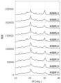
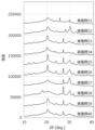
- 1 is an X-ray diffraction pattern of a crystalline sulfide solid electrolyte obtained in an example.
- 1 is an X-ray diffraction pattern of a crystalline sulfide solid electrolyte obtained in an example.
- 1 is an X-ray diffraction pattern of a crystalline sulfide solid electrolyte obtained in an example.
- 1 is an X-ray diffraction pattern of a crystalline sulfide solid electrolyte obtained in an example.
- 1 is an X-ray diffraction pattern of a crystalline sulfide solid electrolyte obtained in an example.
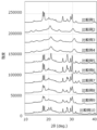
- 1 is an X-ray diffraction pattern of a crystalline sulfide solid electrolyte obtained in a comparative example.
- 1 is an X-ray diffraction pattern of a crystalline sulfide solid electrolyte obtained in a comparative example.
- 1 is a solid-state 31 P-NMR spectrum of a crystalline sulfide solid electrolyte obtained in an example.
- 1 is a solid-state 31 P-NMR spectrum of a crystalline sulfide solid electrolyte obtained in an example.
- the present embodiment The following describes an embodiment of the present invention (hereinafter, may be referred to as “the present embodiment”). Note that in this specification, the upper and lower limit values of the numerical ranges “greater than or equal to,” “less than or equal to,” and “to” can be arbitrarily combined, and the numerical values in the examples can also be used as the upper and lower limit values.
- the solid electrolyte disclosed in Patent Document 1 contains lithium (Li), phosphorus (P), sulfur (S), oxygen (O), and halogen elements, and the inclusion of oxygen improves hydrolysis resistance, i.e., suppresses the generation of hydrogen sulfide, while the inclusion of halogen elements improves ionic conductivity.
- the ionic conductivity is 0.21 to 2.2 mS/cm, which is not high compared to the amount of raw materials containing halogen elements used.
- Raw materials containing halogen elements are expensive among the raw materials for solid electrolytes, so the solid electrolyte disclosed in Patent Document 1 has room for improvement in terms of reducing raw material costs.
- the ionic conductivity is not high compared to the amount of halogen elements used, and there is room for improvement in terms of improving ionic conductivity.
- the solid electrolyte disclosed in Patent Document 1 does not have the diffraction peaks that the crystalline sulfide solid electrolyte of this embodiment has.
- the solid electrolyte glass disclosed in Patent Document 2 is a solid electrolyte glass represented by the above composition formula (1') that contains alkali metals such as lithium, phosphorus, sulfur, halogens, and oxygen, as well as metal elements such as B, Al, and Si.
- Patent Document 2 also describes a glass ceramic obtained by heat-treating the solid electrolyte glass, but the ionic conductivity is 0.80 to 2.2 mS/cm, which is not high considering the amount of raw materials containing halogens used. Therefore, like the solid electrolyte disclosed in Patent Document 1, there is room for improvement in terms of reducing raw material costs and improving ionic conductivity.
- the solid electrolyte disclosed in Patent Document 2 does not have the diffraction peaks that the crystalline sulfide solid electrolyte of this embodiment has.
- Patent Document 3 contains LiI and oxygen, and while the inclusion of LiI improves ionic conductivity, it also reduces chemical stability, but oxygen suppresses the reduction in chemical stability.
- Paragraph [0010] of Patent Document 3 states that the material is highly amorphous to the extent that it has a glass transition point, so that Li ion conductivity can be increased, and the examples disclose an amorphous material that exhibits a halo pattern by X-ray diffraction (XRD) measurement, which is different from crystalline sulfide solid electrolytes.
- XRD X-ray diffraction
- the ionic conductivity is 0.6 to 1.2 mS/cm, which is not high considering the amount of raw material containing halogen elements used. Therefore, like the solid electrolyte disclosed in Patent Document 1, there is room for improvement in terms of reducing raw material costs and improving ionic conductivity.
- Patent Documents 1 to 3 focus on improving ionic conductivity and hydrolysis resistance, but none of them can be said to have high ionic conductivity considering the amount of raw materials containing halogen elements used. Furthermore, Patent Documents 1 to 3 attempt to improve ionic conductivity by using halogen elements, but such a method is known as technical common sense without even needing to mention these patent documents. Considering these, Patent Documents 1 to 3 do not provide any motivation to reduce the amount of halogen elements used in order to improve ionic conductivity. Furthermore, these patent documents do not disclose any idea of adding oxygen atoms to a sulfide solid electrolyte to obtain high ionic conductivity and further reduce raw material costs. Thus, it cannot be said that the conventional techniques of Patent Documents 1 to 3 and the like have produced a sulfide solid electrolyte that has high ionic conductivity and also achieves reduced raw material costs.
- compositions required to obtain crystal structures that exhibit high ionic conductivity such as the thiolicon region II crystal structure and the LGPS crystal structure obtained in the examples described below, were limited to a very small number of compositions. Furthermore, as shown in the comparative examples described below, simply reducing the amount of halogen atoms used without including oxygen atoms does not result in these crystal structures and reduces ionic conductivity.
- the inventors focused on replacing some of the sulfur atoms in a sulfide solid electrolyte with oxygen atoms.
- a material that contains lithium atoms, phosphorus atoms, sulfur atoms, oxygen atoms, and halogen atoms and has a specified diffraction peak has high ionic conductivity and also reduces raw material costs; more specifically, it has high ionic conductivity while reducing raw material costs, and can further improve ionic conductivity when using a large amount of expensive raw materials such as lithium halides.
- Patent Documents 1 to 3 do not pay any attention to the fact that by replacing some of the sulfur atoms with oxygen atoms and by providing a material with a predetermined diffraction peak, it is possible to obtain high ionic conductivity and reduce raw material costs. In particular, they do not pay any attention to the reduction in raw material costs by incorporating oxygen atoms as a substitute for sulfur atoms. In this way, by containing lithium atoms, phosphorus atoms, sulfur atoms, oxygen atoms, and halogen atoms and having a predetermined diffraction peak, it is possible to obtain a material having high ionic conductivity while reducing raw material costs, which is a surprising phenomenon that has not been recognized until now.
- solid electrolyte refers to an electrolyte that maintains a solid state at 25°C under a nitrogen atmosphere.
- the “sulfide solid electrolyte” of this embodiment is a solid electrolyte that contains oxygen atoms in addition to lithium atoms, sulfur atoms, phosphorus atoms, and halogen atoms, and has ionic conductivity due to lithium atoms.
- sulfide solid electrolyte includes both crystalline sulfide solid electrolytes having a crystal structure and amorphous sulfide solid electrolytes.
- a crystalline sulfide solid electrolyte is a solid electrolyte in which a peak derived from a solid electrolyte is observed in the X-ray diffraction pattern in a powder X-ray diffraction (XRD) measurement, and is a material in which the presence or absence of a peak derived from the raw material of the solid electrolyte is not important.
- a crystalline sulfide solid electrolyte includes a crystal structure derived from a solid electrolyte, and may be a crystal structure derived from the solid electrolyte in part or entirely. And, as long as the crystalline sulfide solid electrolyte has the above-mentioned X-ray diffraction pattern, it may include an amorphous sulfide solid electrolyte (also called a "glass component") in part. Therefore, the crystalline sulfide solid electrolyte includes so-called glass ceramics obtained by heating an amorphous solid electrolyte (glass component) to a temperature above the crystallization temperature.
- amorphous sulfide solid electrolyte refers to a solid electrolyte having an X-ray diffraction pattern that is a halo pattern in which no peaks other than those derived from the material are observed in a powder X-ray diffraction (XRD) measurement, regardless of whether or not there are peaks derived from the raw materials of the solid electrolyte.
- XRD powder X-ray diffraction
- the crystalline sulfide solid electrolyte of this embodiment contains lithium atoms, phosphorus atoms, sulfur atoms, oxygen atoms, and halogen atoms, as described above, has the above-mentioned specified diffraction peak, and has a composition represented by the above-mentioned specified composition formula, so that it has high ionic conductivity and can also reduce raw material costs.
- the high ionic conductivity as described above, it is known that the use of lithium halide can improve ionic conductivity.
- lithium halide is expensive, and reducing its usage leads to reduced raw material costs, but usually leads to a decrease in ionic conductivity. In other words, it can be said that reduced raw material costs and high ionic conductivity are in a trade-off relationship.
- the crystalline sulfide solid electrolyte of this embodiment has a predetermined diffraction peak in X-ray diffraction measurement and a predetermined peak in solid 31 P-NMR measurement, while replacing some of the sulfur atoms with oxygen atoms, and has a composition represented by the above-mentioned predetermined composition formula, thereby reducing raw material costs. That is, even if the amount of raw material containing halogen atoms such as lithium halide is reduced, it has high ionic conductivity.
- the amount of raw material containing halogen atoms such as lithium halide when large, it has a higher ionic conductivity even if it is about the same as the amount used in the conventional technology such as Patent Documents 1 to 3 (hereinafter, when simply referred to in this specification as "high ionic conductivity", it means either a high ionic conductivity obtained even if the amount of raw material containing halogen atoms is reduced, a higher ionic conductivity obtained when the amount is large, or both of these.).
- the crystalline sulfide solid electrolyte of this embodiment can achieve high ionic conductivity and further reduction in raw material costs.
- the crystalline sulfide solid electrolyte according to the second aspect of the present embodiment is the same as the first aspect, In the composition formula (1), the product of x and y (x ⁇ y) is 0.0010 or more and 2.7 or less. That is it.
- x and y can each be any value selected from the above range, but if the product of x and y is within the above range, the value is well-balanced, making it easier to obtain a crystalline sulfide solid electrolyte with high ionic conductivity while reducing raw material costs. More specifically, this is considered as follows. As described below, x means the substitution rate of oxygen atoms when replacing a part of sulfur atoms with oxygen atoms, and y means the content of halogen atoms, so that if the product is within the above range, it means that the amount of oxygen atoms and the amount of halogen atoms can be well-balanced.
- the crystal lattice size can be reduced, and by further containing the amount of oxygen atoms and the amount of halogen atoms in a balanced manner, it is possible to stabilize crystal structures with high ionic conductivity, such as a thiolicon region II type crystal structure and a LGPS type crystal structure. Therefore, it is thought that the content of halogen atoms, which has been considered necessary for stabilizing these crystal structures that can exhibit high ionic conductivity, can be reduced, that is, it is easier to reduce raw material costs and achieve high ionic conductivity at the same time.
- the crystalline sulfide solid electrolyte according to the third aspect of the present embodiment is the first or second aspect described above, A peak due to PO 4 3- was observed at 9.2 ⁇ 5.0 ppm by solid-state 31 P-NMR measurement.
- the crystalline sulfide solid electrolyte according to the fourth aspect is any one of the first to third aspects described above, A peak due to PS 2 O 2 3- was observed at 70.3 ⁇ 5.0 ppm by solid-state 31 P-NMR measurement. That is it.
- the crystalline sulfide solid electrolyte according to the fifth aspect of the present embodiment is any one of the first to fourth aspects described above, At least two exothermic peaks are measured in a thermogravimetric differential calorimetry (measured at a heating rate of 10° C./min), and the temperature difference between the peak tops of the two exothermic peaks is 20° C. or more and 110° C. or less. That is it.
- the crystalline sulfide solid electrolyte according to the sixth aspect of the present embodiment is any one of the first to fifth aspects described above,
- the halogen atom is at least one halogen atom selected from a chlorine atom, a bromine atom, and an iodine atom.
- the crystalline sulfide solid electrolyte according to the seventh aspect is any one of the first to sixth aspects,
- the halogen atoms are bromine and iodine atoms. That is it.
- halogen atom selected from chlorine, bromine and iodine atoms as the halogen atom, that is, a chlorine atom, a bromine atom or an iodine atom alone or two or more halogen atoms selected from these atoms, it becomes easier to obtain a higher ionic conductivity.
- halogen atom selected from chlorine, bromine and iodine atoms that is, a chlorine atom, a bromine atom or an iodine atom alone or two or more halogen atoms selected from these atoms.
- bromine and iodine atoms simultaneously, it becomes easier to obtain a particularly high ionic conductivity.
- the crystalline sulfide solid electrolyte according to the eighth aspect of the present embodiment is any one of the first to seventh aspects, In the composition formula (1), y satisfies 14.0 ⁇ y ⁇ 25.0. That is it.
- composition formula (1) when y is 14.0 ⁇ y ⁇ 25.0, this means that the amount of raw material containing halogen atoms is greater, that is, the content of halogen atoms in the crystalline sulfide solid electrolyte is greater, and this is the amount of use that is also considered for sulfide solid electrolytes in the prior art.
- the crystalline sulfide solid electrolyte according to a ninth aspect of the present embodiment is any one of the first to eighth aspects described above,
- the ionic conductivity is 0.85 mS/cm or more.
- the crystalline sulfide solid electrolyte according to the tenth aspect is any one of the first to ninth aspects,
- the ionic conductivity is 2.5 mS/cm or more. That is it.
- the crystalline sulfide solid electrolyte of this embodiment contains lithium atoms, phosphorus atoms, sulfur atoms, oxygen atoms, and halogen atoms, and has a predetermined diffraction peak, so that the ionic conductivity is high and falls within the above range.
- a crystalline sulfide solid electrolyte according to an eleventh aspect of the present embodiment is any one of the first to tenth aspects described above, does not contain at least one metal atom selected from sodium atoms, boron atoms, aluminum atoms, silicon atoms, germanium atoms, arsenic atoms, selenium atoms, antimony atoms, tellurium atoms, lead atoms, and bismuth atoms; That is it.
- a crystalline sulfide solid electrolyte according to a twelfth aspect of the present embodiment is any one of the first to eleventh aspects,
- the oxygen atom is derived from P2O5 ; That is it.
- a crystalline sulfide solid electrolyte according to a thirteenth aspect of the present embodiment is any one of the first to twelfth aspects, It is a glass ceramic, That is it.
- glass ceramics are obtained by heating an amorphous solid electrolyte (glass component) to a temperature above the crystallization temperature.
- the crystalline sulfide solid electrolyte of this embodiment is an extremely useful solid electrolyte regardless of the amount of raw material containing halogen atoms.
- the crystalline sulfide solid electrolyte according to a fifteenth aspect of the present embodiment is the fourteenth aspect, A peak due to PO 4 3- was observed at 9.2 ⁇ 5.0 ppm by solid-state 31 P-NMR measurement.
- the crystalline sulfide solid electrolyte according to the sixteenth aspect is the crystalline sulfide solid electrolyte according to the fourteenth or fifteenth aspect, A peak due to PS 2 O 2 3- was observed at 70.3 ⁇ 5.0 ppm by solid-state 31 P-NMR measurement. That is it.
- composition formula (1) (100-y) (0.5) (Li 3+2z P(S 1-x O x ) 4+z )+(y)LiX (1)
- x, y, and z each satisfy 0.00060 ⁇ x ⁇ 0.15, 3.0 ⁇ y ⁇ 25.0, and ⁇ 0.17 ⁇ z ⁇ 1.5.
- X represents a halogen atom.
- the peak position of the diffraction peak of the crystalline sulfide solid electrolyte of this embodiment may vary depending on the peak position, but may vary within a range of ⁇ 0.6 ° to ⁇ 0.5 °.
- the measurement method of the X-ray diffraction measurement using CuK ⁇ radiation in this specification will be described in the examples.
- the crystalline sulfide solid electrolyte of this embodiment may have any of the above crystal structures as long as it has the above diffraction peak. And, since such a diffraction peak is expressed, even if the amount of raw material containing halogen atoms is small (i.e., the content of halogen atoms in the crystalline sulfide solid electrolyte is at least), high ionic conductivity can be obtained, and when the amount of raw material containing halogen atoms is large (i.e., when the content of halogen atoms in the crystalline sulfide solid electrolyte is large), it has a high ionic conductivity equal to or higher than that of a conventional sulfide solid electrolyte containing halogen atoms to the same extent.
- mainly having a thiolisicon region II type crystal structure means that all of the above diffraction peaks attributable to the thiolisicon region II type crystal structure can be confirmed
- mainly having an LGPS type crystal structure means that all of the above diffraction peaks attributable to the LGPS type crystal structure can be confirmed
- mixed means that both diffraction peaks can be confirmed, or that some of the both diffraction peaks overlap and cannot be separated.
- the certain crystal structure is mainly present, and if it is in between, i.e., more than 40% but less than 60%, it can be considered that the certain crystal structure is mixed.
- the term "mainly” can also be determined by the intensity of a certain diffraction peak when the thiolisicon region II type crystal structure and the LGPS type crystal structure coexist.
- Examples of the thio-LISICON region II type crystal structure include Li4 - xGe1 -xPxS4- based thio -LISICON region II type crystal structure (see Kanno et al., Journal of the Electrochemical Society, 148(7)A742-746(2001)), and crystal structures similar to Li4 -xGe1 -xPxS4 - based thio-LISICON region II type (see Solid State Ionics, 177(2006), 2721-2725).
- the LGPS type crystal structure may be a crystal structure having a composition represented by Li3 + xPS4 -yOy (wherein x satisfies -1 ⁇ x ⁇ 1 and y satisfies 0 ⁇ y ⁇ 4) (also referred to as "Li-P-S-O based sulfide solid electrolyte").
- the notation of the crystal structure as "Li 4-x Ge 1-x P x S 4 thio-LISICON Region II type” means that it was found in the above document as a crystal structure composed of Li, Ge, P and S atoms. Since the sulfide solid electrolyte obtained by the manufacturing method of this embodiment contains lithium atoms, phosphorus atoms, sulfur atoms and halogen atoms, it may not be represented by the composition formula of "Li 4-x Ge 1-x P x S 4 " in "Li 4-x Ge 1-x P x S 4 thio-LISICON Region II type".
- the sulfide solid electrolyte obtained by the manufacturing method of this embodiment has the same diffraction peak as the above-mentioned "thiolicon region II type crystal structure" (including the above-mentioned “similar crystal structure"), it can be said that the sulfide solid electrolyte has a thiolicon region II type crystal structure formed by lithium atoms, phosphorus atoms, sulfur atoms and halogen atoms. This is not limited to the thiolicon region II type crystal structure, but also applies to the LGPS type crystal structure.
- these peaks are expressed, and as a result, higher ionic conductivity is obtained.
- the positions of these diffraction peaks vary within the ranges of ⁇ 0.7°, ⁇ 0.6°, and ⁇ 0.5°.
- the thiolicon region II type crystal structure and the LGPS type crystal structure preferably possessed by the crystalline sulfide solid electrolyte of the present embodiment can be formed without using an amorphous solid electrolyte (glass component), or can be formed as a so-called glass ceramic obtained by heating an amorphous solid electrolyte (glass component) to a crystallization temperature or higher.
- the crystalline sulfide solid electrolyte of the present embodiment is preferably a glass ceramic.
- the crystalline sulfide solid electrolyte of the present embodiment contains lithium atoms, phosphorus atoms, sulfur atoms, oxygen atoms, and halogen atoms.
- halogen atoms include fluorine, chlorine, bromine and iodine atoms. Among these halogen atoms, chlorine, bromine and iodine atoms are preferred, and bromine and iodine atoms are preferred.
- the halogen atoms may include these atoms alone or multiple types of atoms.
- the oxygen atoms in the crystalline sulfide solid electrolyte of this embodiment are preferably derived from P 2 O 5.
- the method for producing the crystalline sulfide solid electrolyte of this embodiment is not particularly limited as long as it contains lithium atoms, phosphorus atoms, sulfur atoms, oxygen atoms, and halogen atoms and has the above-mentioned diffraction peak.
- P 2 O 5 it is preferable to use P 2 O 5 as a raw material containing oxygen atoms.
- the crystalline sulfide solid electrolyte of this embodiment preferably does not contain at least one metal atom selected from sodium atoms, boron atoms, aluminum atoms, silicon atoms, germanium atoms, arsenic atoms, selenium atoms, antimony atoms, tellurium atoms, lead atoms, and bismuth atoms.
- a crystalline sulfide solid electrolyte having high ionic conductivity can be easily obtained while reducing raw material costs.
- not containing metal atoms literally means not containing any metal atoms at all (i.e., 0 mass%), but also includes cases where metal atoms are unavoidably mixed in.
- the content is 3 mass% or less, 2 mass% or less, 1 mass%, 0.5 mass% or less, 0.3 mass% or less, or 0.1 mass% or less based on the total amount of the crystalline sulfide solid electrolyte.
- the type and composition of the atoms constituting the crystalline sulfide solid electrolyte of this embodiment can be confirmed, for example, by an ICP emission spectrometer.
- x, y, and z satisfy 0.00060 ⁇ x ⁇ 0.15, 3.0 ⁇ y ⁇ 25.0, and ⁇ 0.17 ⁇ z ⁇ 1.5.
- X represents a halogen atom.
- x means the substitution rate of oxygen atoms when some of the sulfur atoms are replaced with oxygen atoms.
- x satisfies 0.00060 ⁇ x ⁇ 0.15, and from the viewpoint of making it easier to express the above diffraction peak, thereby reducing raw material costs, and obtaining high ionic conductivity, it is preferably 0.0010 or more, more preferably 0.0030 or more, and even more preferably 0.0050 or more, and the upper limit is preferably 0.12 or less, more preferably 0.085 or less, even more preferably 0.065 or less, and even more preferably 0.045 or less.
- Typical numerical ranges for x are 0.00060 or more and 0.15 or less, 0.00060 or more and 0.12 or less, 0.00060 or more and 0.085 or less, 0.00060 or more and 0.065 or less, 0.00060 or more and 0.045 or less, 0.0010 or more and 0.15 or less, 0.0010 or more and 0.12 or less, 0.0010 or more and 0.085 or less, 0.0010 or more and 0.065 or less, 0.0010 or more and 0.
- Preferred examples include 0.045 or less, 0.0030 or more and 0.15 or less, 0.0030 or more and 0.12 or less, 0.0030 or more and 0.085 or less, 0.0030 or more and 0.065 or less, 0.0030 or more and 0.045 or less, 0.0050 or more and 0.15 or less, 0.0050 or more and 0.12 or less, 0.0050 or more and 0.085 or less, 0.0050 or more and 0.065 or less, and 0.0050 or more and 0.045 or less.
- composition formula (1) means the content of halogen atoms.
- the composition formula (1) is expressed in the form of LiX (lithium halide), but the raw material containing halogen atoms is not limited to lithium halide, and may be, for example, an elemental halogen, as described later.
- y satisfies 3.0 ⁇ y ⁇ 25.0, and from the viewpoint of making it easier to express the above diffraction peaks, thereby reducing raw material costs, and obtaining high ionic conductivity, is preferably 4.5 or more, more preferably 7.0 or more, even more preferably 9.0 or more, still more preferably 10.5 or more, particularly preferably more than 14.0, even more particularly preferably 14.5 or more, and the upper limit is preferably 22.0 or less, more preferably 21.0 or less, even more preferably 19.0 or less, and even more preferably 17.0 or less.
- Typical numerical ranges for y are 3.0 or more and less than 25.0, 3.0 or more and less than 22.0, 3.0 or more and less than 21.0, 3.0 or more and less than 19.0, 3.0 or more and less than 17.0, 4.5 or more and less than 25.0, 4.5 or more and less than 22.0, 4.5 or more and less than 21.0, 4.5 or more and less than 19.0, 4.5 or more and less than 17.0, 7.0 or more and less than 25.0, 7.0 or more and less than 22.0, 7.0 or more and less than 21.0, 7.0 or more and less than 19.0, 7.0 or more and less than 17.0, 9.0 or more and less than 25.0, 9.0 or more and less than 22.0, and 9.0 or more and less than 21.
- Preferred examples include 0 or less, 9.0 or more and 19.0 or less, 9.0 or more and 17.0 or less, 10.5 or more and less than 25.0, 10.5 or more and 22.0 or less, 10.5 or more and 21.0 or less, 10.5 or more and 19.0 or less, 10.5 or more and 17.0 or less, more than 14.0 and less than 25.0, more than 14.0 and 22.0 or less, more than 14.0 and 21.0 or less, more than 14.0 and 19.0 or less, more than 14.0 and 17.0 or less, 14.5 or more and less than 25.0, 14.5 or more and 22.0 or less, 14.5 or more and 21.0 or less, 14.5 or more and 19.0 or less, and 14.5 or more and 17.0 or less.
- the value z indicates the deviation of the ratio of lithium atoms to sulfur atoms from the Li 3 PS 4 structure which is the basic skeleton of the thiolicon region II type crystal structure and the LGPS type crystal structure.
- z satisfies -0.17 ⁇ z ⁇ 1.5, and from the viewpoint of easily expressing the above diffraction peak, thereby reducing raw material costs, and obtaining high ionic conductivity, it is preferably -0.15 or more, more preferably -0.11 or more, even more preferably -0.080 or more, still more preferably -0.040 or more, and particularly preferably -0.020 or more, and the upper limit is preferably 1.0 or less, more preferably 0.90 or less, even more preferably 0.60 or less, still more preferably 0.40 or less, and particularly preferably 0.20 or less.
- Typical numerical ranges for z are -0.17 or more and 1.5 or less, -0.17 or more and 1.0 or less, -0.17 or more and 0.90 or less, -0.17 or more and 0.60 or less, -0.17 or more and 0.40 or less, -0.17 or more and 0.20 or less, -0.15 or more and 1.5 or less, -0.15 or more and 1.0 or less, -0.15 or more and 0.90 or less, -0.15 or more and 0.60 or less, -0.15 or more and 0.40 or less, -0.15 or more and 0.20 or less, -0.11 or more and 1.5 or less, -0.11 or more and 1.0 or less, -0.11 or more and 0.90 or less, -0.11 or more and 0.60 or less, -0.11 or more and 0.40 or less, -0.11 or more and 0.20 or less, -0.080 Preferred examples include 1.5 or less, -0.080 or more and 1.0 or less, -0.080 or more and 0.
- the product of x and y (x x y) is preferably 0.0010 or more, more preferably 0.0050 or more, even more preferably 0.010 or more, even more preferably 0.025 or more, and particularly preferably 0.050 or more, and the upper limit is preferably 2.7 or less, more preferably 2.0 or less, even more preferably 1.25 or less, even more preferably 0.75 or less, particularly preferably 0.60 or less, even more particularly preferably 0.45 or less, and even more particularly preferably 0.28 or less.
- x and y can each take any value selected from the above range, but by adopting x and y such that the product of x and y (x x y) is within the above range, the above x and y take a balanced value, which makes it easier to express the above diffraction peak and makes it easier to obtain a crystalline sulfide solid electrolyte having high ionic conductivity while reducing raw material costs.
- typical numerical ranges for the product of x and y (x ⁇ y) are 0.0010 or more and 2.7 or less, 0.0010 or more and 2.0 or less, 0.0010 or more and 1.25 or less, 0.0010 or more and 0.75 or less, 0.0010 or more and 0.60 or less, 0.0010 or more and 0.45 or less, 0.0010 or more and 0.28 or less, 0.0050 or more and 2.7 or less, 0.0050 or more and 2.0 or less, 0.0050 or more and 1.25 or less, 0.0050 or more and 0.75 or less, 0.0050 or more and 0.60 or less, 0.0050 or more and 0.45 or less, 0.0050 or more and 0.28 or less, 0.010 or more and 2.7 or less, 0.010 or more and 2.0 or less, 0.010 or less Preferred examples include 1.25 or less, 0.010 to 0.75, 0.010 to 0.60, 0.010 to 0.45, 0.010 to 0.28, 0.025 to 2.7, 0.025 to 2.0, 0.025 or less
- X represents a halogen atom.
- the halogen atom is the same as the halogen atom described as the constituent atom of the crystalline sulfide solid electrolyte of this embodiment.
- the crystalline sulfide solid electrolyte of this embodiment is preferably one in which a peak due to PSO 3 3- is observed at 39.6 ⁇ 5.0 ppm by solid-state 31 P-NMR measurement. It is also preferable that a peak due to PO 4 3- is observed at 9.2 ⁇ 5.0 ppm, and further a peak due to PS 2 O 2 3- is observed at 70.3 ⁇ 5.0 ppm.
- the measurement method of solid-state 31 P-NMR measurement in this specification will be described in the examples.
- the peak by solid-state 31 P-NMR measurement may be within the range of ⁇ 5.0 ppm, and further within the range of ⁇ 4.0 ppm, ⁇ 3.0 ppm, and ⁇ 2.0 ppm.
- the peak due to PSO 3 3- , the peak due to PO 4 3- , and the peak due to PS 2 O 2 3- indicate that at least the crystalline sulfide solid electrolyte of this embodiment has oxygen atoms in its structure.
- a crystalline sulfide solid electrolyte having the above peaks in the solid-state 31 P-NMR spectrum has oxygen atoms incorporated into its structure, i.e., some of the sulfur atoms are replaced with oxygen atoms, and therefore has two diffraction peaks in the X-ray diffraction measurement using the CuK ⁇ ray. As a result, higher ionic conductivity is obtained.
- thermogravimetric differential calorimetry measured at a heating rate of 10° C./min
- the temperature difference between the peak tops of the two exothermic peaks is 20° C. or more and 110° C. or less.
- the lower limit of the temperature difference is preferably 30°C or more, more preferably 35°C or more, even more preferably 45°C or more, even more preferably 50°C or more, and particularly preferably 55°C or more, and the upper limit is preferably 100°C or less, more preferably 95°C or less, and even more preferably 90°C or less.
- the temperature (Tc1) of the peak top of the exothermic peak on the low temperature side is preferably 180°C or higher, more preferably 185°C or higher, even more preferably 190°C or higher, and even more preferably 195°C or higher, with the upper limit being preferably 330°C or lower, more preferably 325°C or lower, even more preferably 310°C or lower, and even more preferably 300°C or lower.
- the temperature (Tc2) of the peak top of the exothermic peak on the high temperature side is preferably 180°C or higher, more preferably 190°C or higher, even more preferably 220°C or higher, even more preferably 240°C or higher, and particularly preferably 255°C or higher.
- the fact that these two exothermic peaks are observed means that it is easy to obtain crystalline sulfide solid electrolytes, particularly crystalline sulfide solid electrolytes having a thiolicon region II crystal structure or an LGPS crystal structure that exhibits high ionic conductivity. Therefore, if the above two exothermic peaks are observed in thermogravimetric differential calorimetry, it is easy to obtain crystalline sulfide solid electrolytes having high ionic conductivity while reducing raw material costs.
- the ionic conductivity of the crystalline sulfide solid electrolyte of this embodiment can be 0.85 mS/cm or more, further 1.0 mS/cm or more, 1.5 mS/cm or more, 2.0 mS/cm or more, 2.5 mS/cm or more, 3.0 mS/cm or more, 3.5 mS/cm or more, 4.0 mS/cm or more, 4.4 mS/cm or more, or 5.0 mS/cm or more.
- the crystalline sulfide solid electrolyte of this embodiment has high ionic conductivity.
- the ionic conductivity can be 0.85 mS/cm or more, or even 1.0 mS/cm or more, 1.5 mS/cm or more, or 2.0 mS/cm or more.
- the ionic conductivity can be 2.0 mS/cm or more, 2.5 mS/cm or more, 3.0 mS/cm or more, 3.5 mS/cm or more, 4.0 mS/cm or more, 4.4 mS/cm or more, or 5.0 mS/cm or more.
- the lithium atom, phosphorus atom, sulfur atom, oxygen atom, and halogen atom are contained, and the predetermined diffraction peak in the X-ray diffraction measurement and the predetermined peak in the solid 31 P-NMR measurement are the same as those described in the crystalline sulfide solid electrolyte of the present embodiment.
- the peak due to PO 4 3- is observed at 9.2 ⁇ 5.0 ppm, and the peak due to PS 2 O 2 3- is observed at 0.3 ⁇ 5.0 ppm, for the predetermined peak in the solid 31 P-NMR measurement.
- high ionic conductivity can be obtained by having a structure in which the lithium atom, phosphorus atom, sulfur atom, oxygen atom, and halogen atom exhibit a predetermined diffraction peak in the X-ray diffraction measurement and a predetermined peak in the solid 31 P-NMR measurement.
- the composition of the crystalline sulfide solid electrolyte of another embodiment is not particularly limited as long as it contains lithium atoms, phosphorus atoms, sulfur atoms, oxygen atoms, and halogen atoms, has a predetermined diffraction peak, and a peak due to a predetermined PSO 3 3- is observed. From the viewpoint of facilitating the appearance of a predetermined diffraction peak in X-ray diffraction measurement and a predetermined peak in solid-state 31 P-NMR measurement, it is preferable to have a composition represented by the above composition formula (1).
- the crystalline sulfide solid electrolyte of the present embodiment has high ionic conductivity while reducing raw material costs, and has excellent battery performance. Therefore, for example, it is preferably used in combination with an electrode active material as an electrode mixture or in a lithium ion battery.
- the sulfide solid electrolyte of this embodiment When used in a lithium ion battery, it may be used in the positive electrode layer, the negative electrode layer, or the electrolyte layer. When used in a positive electrode layer, it can be used as an electrode mixture containing the crystalline sulfide solid electrolyte of this embodiment and a positive electrode active material, and when used in a negative electrode layer, it can be used as an electrode mixture containing the crystalline sulfide solid electrolyte of this embodiment and a negative electrode active material. In addition, the crystalline sulfide solid electrolyte may be used as it is in the electrolyte layer.
- the electrode mixture contains the crystalline sulfide solid electrolyte of the present embodiment and an electrode active material.
- the electrode active material a positive electrode active material or a negative electrode active material is adopted depending on whether the electrode mixture is used for a positive electrode or a negative electrode.
- the positive electrode active material can be any material that can promote a battery chemical reaction involving the movement of lithium ions resulting from atoms that are used to exhibit ionic conductivity in relation to the negative electrode active material, preferably lithium atoms, and is not particularly limited.
- positive electrode active materials that can insert and remove lithium ions include oxide-based positive electrode active materials and sulfide-based positive electrode active materials.
- LMO lithium manganese oxide
- LCO lithium cobalt oxide
- NMC lithium nickel manganese cobalt oxide
- NCA lithium nickel cobalt aluminate
- LNCO lithium nickel cobalt oxide
- sulfide-based positive electrode active materials include titanium sulfide (TiS 2 ), molybdenum sulfide (MoS 2 ), iron sulfide (FeS, FeS 2 ), copper sulfide (CuS), and nickel sulfide (Ni 3 S 2 ).
- TiS 2 titanium sulfide
- MoS 2 molybdenum sulfide
- FeS, FeS 2 iron sulfide
- CuS copper sulfide
- Ni 3 S 2 nickel sulfide
- the positive electrode active material may be used alone or in combination of two or more kinds.
- the negative electrode active material can be used without any particular limitation as long as it can promote a battery chemical reaction accompanied by the movement of lithium ions caused by lithium atoms, such as an atom that is used as an atom that exhibits ion conductivity, preferably a metal that can form an alloy with lithium atoms, an oxide thereof, an alloy of the metal with lithium atoms, etc.
- a negative electrode active material capable of inserting and removing lithium ions any material known as a negative electrode active material in the battery field can be used without any limitation.
- Examples of such negative electrode active materials that can be used in the case of constituting a lithium ion battery include silicon-based active materials such as Si, Si alloys, and silicon oxide; carbon-based active materials such as graphite and hard carbon; various oxide-based active materials such as lithium titanate; metals that can form metal lithium or alloys with metal lithium, such as metal lithium, indium metal, aluminum metal, silicon metal, and tin metal, oxides of these metals, and alloys of these metals with metal lithium.
- the electrode active material may have a coating layer on its surface.
- Materials for forming the coating layer include ion conductors such as nitrides, oxides, and composites of atoms, preferably lithium atoms, that exhibit ion conductivity in the sulfide solid electrolyte.
- conductors having a lysicone-type crystal structure such as Li 4-2x Zn x GeO 4 , which has a main structure of lithium nitride (Li 3 N) and Li 4 GeO 4
- conductors having a thiolysicone-type crystal structure such as Li 4-x Ge 1-x P x S 4, which has a Li 3 PO 4 type skeleton structure
- conductors having a perovskite-type crystal structure such as La 2/3-x Li 3x TiO 3
- conductors having a NASICON-type crystal structure such as LiTi 2 (PO 4 ) 3 .
- lithium titanates such as Li y Ti 3-y O 4 (0 ⁇ y ⁇ 3) and Li 4 Ti 5 O 12 (LTO)
- lithium metal oxides of metals belonging to Group 5 of the periodic table such as LiNbO 3 and LiTaO 3
- oxide-based conductors such as Li 2 O—B 2 O 3 —P 2 O 5 , Li 2 O—B 2 O 3 —ZnO, and Li 2 O—Al 2 O 3 —SiO 2 —P 2 O 5 —TiO 2 .
- An electrode active material having a coating layer can be obtained, for example, by applying a solution containing various atoms constituting the material forming the coating layer to the surface of an electrode active material, and then baking the electrode active material after application at a temperature of preferably 200° C. or higher and 400° C. or lower.
- the solution containing various atoms may be a solution containing alkoxides of various metals such as lithium ethoxide, titanium isopropoxide, niobium isopropoxide, tantalum isopropoxide, etc.
- the solvent may be an alcohol solvent such as ethanol or butanol, an aliphatic hydrocarbon solvent such as hexane, heptane, or octane, or an aromatic hydrocarbon solvent such as benzene, toluene, or xylene.
- the above attachment may be performed by immersion, spray coating, or the like.
- the firing temperature is preferably 200°C or higher and 400°C or lower, and more preferably 250°C or higher and 390°C or lower, and the firing time is usually about 1 minute to 10 hours, and preferably 10 minutes to 4 hours.
- the coverage of the coating layer is preferably 90% or more, more preferably 95% or more, and even more preferably 100% based on the surface area of the electrode active material, that is, the entire surface is preferably covered.
- the thickness of the coating layer is preferably 1 nm or more, more preferably 2 nm or more, and the upper limit is preferably 30 nm or less, more preferably 25 nm or less.
- the thickness of the coating layer can be measured by cross-sectional observation using a transmission electron microscope (TEM), and the coverage rate can be calculated from the thickness of the coating layer, the elemental analysis value, and the BET specific surface area.
- TEM transmission electron microscope
- Examples of the conductive material from the viewpoint of improving battery performance by improving electronic conductivity, include carbon-based materials such as artificial graphite, graphite carbon fiber, resin-calcined carbon, pyrolytic vapor-grown carbon, coke, mesocarbon microbeads, furfuryl alcohol resin-calcined carbon, polyacene, pitch-based carbon fiber, vapor-grown carbon fiber, natural graphite, and non-graphitizable carbon.
- carbon-based materials such as artificial graphite, graphite carbon fiber, resin-calcined carbon, pyrolytic vapor-grown carbon, coke, mesocarbon microbeads, furfuryl alcohol resin-calcined carbon, polyacene, pitch-based carbon fiber, vapor-grown carbon fiber, natural graphite, and non-graphitizable carbon.
- the binder is not particularly limited as long as it can impart functions such as binding property and flexibility, and examples thereof include fluorine-based polymers such as polytetrafluoroethylene and polyvinylidene fluoride, thermoplastic elastomers such as butylene rubber and styrene-butadiene rubber, and various resins such as acrylic resins, acrylic polyol resins, polyvinyl acetal resins, polyvinyl butyral resins, and silicone resins.
- fluorine-based polymers such as polytetrafluoroethylene and polyvinylidene fluoride
- thermoplastic elastomers such as butylene rubber and styrene-butadiene rubber
- various resins such as acrylic resins, acrylic polyol resins, polyvinyl acetal resins, polyvinyl butyral resins, and silicone resins.
- the compounding ratio (mass ratio) of the electrode active material to the crystalline sulfide solid electrolyte in the electrode mixture is preferably 99.5:0.5 to 40:60, more preferably 99:1 to 50:50, and even more preferably 98:2 to 60:40, in order to improve battery performance and take into consideration manufacturing efficiency.
- the content of the conductive material in the electrode mixture is not particularly limited, but in consideration of improving battery performance and production efficiency, the content is preferably 0.5 mass% or more, more preferably 1 mass% or more, and even more preferably 1.5 mass% or more, and the upper limit is preferably 10 mass% or less, preferably 8 mass% or less, and even more preferably 5 mass% or less.
- the content of the binder in the electrode mixture is not particularly limited, but in consideration of improving battery performance and production efficiency, the content is preferably 1 mass % or more, more preferably 3 mass % or more, and even more preferably 5 mass % or more, and the upper limit is preferably 20 mass % or less, preferably 15 mass % or less, and even more preferably 10 mass % or less.
- the crystalline sulfide solid electrolyte of the present embodiment can also be used in a lithium ion battery as described above.
- the lithium ion battery can include at least one selected from the sulfide solid electrolyte of the present embodiment and the electrode mixture.
- the lithium ion battery there are no particular limitations on the configuration of the lithium ion battery, so long as it contains the crystalline sulfide solid electrolyte of the present embodiment described above and an electrode composite material containing the same, and it may have the configuration of a commonly used lithium ion battery.
- the lithium ion battery preferably includes, for example, a positive electrode layer, a negative electrode layer, an electrolyte layer, and a current collector.
- the positive electrode layer and the negative electrode layer preferably use an electrode mixture containing the crystalline sulfide solid electrolyte of the present embodiment, and the electrolyte layer preferably uses the crystalline sulfide solid electrolyte of the present embodiment.
- the current collector may be any known material.
- a layer of a material that reacts with the solid electrolyte such as Au, Pt, Al, Ti, or Cu, coated with Au or the like can be used.
- the crystalline sulfide solid electrolyte of the present embodiment described above can be obtained by a production method including mixing raw material components including, for example, lithium atoms, sulfur atoms, phosphorus atoms, oxygen atoms, and halogen atoms.
- the raw material-containing material includes lithium atoms, phosphorus atoms, sulfur atoms, oxygen atoms, and halogen atoms. More specifically, the raw material-containing material includes a substance (hereinafter also referred to as "raw material") that includes one or more types of atoms selected from the group consisting of these atoms, and preferably includes two or more types of raw materials.
- the raw material include lithium sulfide; phosphorus sulfide such as diphosphorus trisulfide (P 2 S 3 ) and diphosphorus pentasulfide (P 2 S 5 ); and other raw materials containing at least two types of atoms selected from the above-mentioned atoms, as well as raw materials consisting of one type of atom selected from the above-mentioned atoms, such as elemental phosphorus and elemental sulfur.
- phosphorus sulfide such as diphosphorus trisulfide (P 2 S 3 ) and diphosphorus pentasulfide (P 2 S 5 )
- other raw materials containing at least two types of atoms selected from the above-mentioned atoms as well as raw materials consisting of one type of atom selected from the above-mentioned atoms, such as elemental phosphorus and elemental sulfur.
- lithium sulfide and phosphorus sulfides such as diphosphorus trisulfide (P 2 S 3 ) and diphosphorus pentasulfide (P 2 S 5 ) are preferred, and among the phosphorus sulfides, diphosphorus pentasulfide (P 2 S 5 ) is preferred.
- the raw material may preferably include a substance containing a halogen atom, for example, a lithium halide such as lithium fluoride, lithium chloride, lithium bromide, or lithium iodide; or an elemental halogen such as fluorine (F 2 ), chlorine (Cl 2 ), bromine (Br 2 ), or iodine (I 2 ).
- a lithium halide such as lithium fluoride, lithium chloride, lithium bromide, or lithium iodide
- an elemental halogen such as fluorine (F 2 ), chlorine (Cl 2 ), bromine (Br 2 ), or iodine (I 2 ).
- a substance containing an oxygen atom is also preferred.
- diphosphorus pentoxide (P 2 O 5 ), lithium oxide (Li 2 O), lithium hydroxide (LiOH), etc. are representatively preferred.
- diphosphorus pentoxide (P 2 O 5 ) is preferred as described above.
- the raw materials include substances containing at least one atom selected from the group consisting of lithium atoms, phosphorus atoms, sulfur atoms, oxygen atoms, and halogen atoms, such as phosphorus halides such as various phosphorus fluorides ( PF3 , PF5 ), various phosphorus chlorides ( PCl3 , PCl5 , P2Cl4 ), various phosphorus bromides ( PBr3 , PBr5 ), and various phosphorus iodides ( PI3 , P2I4 ); thiophosphoryl fluoride ( PSF3 ), thiophosphoryl chloride ( PSCl3 ), thiophosphoryl bromide ( PSBr3 ), thiophosphoryl iodide ( PSI3 ), thiophosphoryl fluoride dichloride ( PSCl2F ), thiophosphoryl fluoride dibromide ( PSBr2F ), and the like.
- phosphorus halides such
- thiophosphoryl halides such as thiophosphoryl halides F); lithium compounds such as lithium oxide, lithium hydroxide, and lithium carbonate; alkali metal sulfides such as sodium sulfide, potassium sulfide, rubidium sulfide, and cesium sulfide; metal sulfides such as silicon sulfide, germanium sulfide, boron sulfide, gallium sulfide, tin sulfide (SnS, SnS 2 ), aluminum sulfide, and zinc sulfide; phosphate compounds such as sodium phosphate and lithium phosphate; halides of alkali metals other than lithium, such as sodium halides such as sodium iodide, sodium fluoride, sodium chloride, and sodium bromide; metal halides such as aluminum halides, silicon halides, germanium halides, arsenic halides, selenium halides, tin
- a material that acts as a solid electrolyte such as Li 3 PS 4 or Li 7 P 3 S 11 , which includes a PS 4 structure, can be used as a raw material.
- Li 3 PS 4 when Li 3 PS 4 is used as a raw material, Li 3 PS 4 may be prepared in advance by producing it using, for example, lithium sulfide and diphosphorus pentasulfide, and this may be used as a raw material.
- the raw materials such as lithium sulfide are preferably in the form of particles, which makes it easier to mix the raw materials together and thus facilitates the production of a crystalline sulfide solid electrolyte.
- the average particle size ( D50 ) of the raw material particles may be, for example, 0.1 ⁇ m to 1000 ⁇ m, 0.5 ⁇ m to 100 ⁇ m, or 1 ⁇ m to 20 ⁇ m, taking into consideration the reaction of the raw material, handling, etc.
- the average particle size ( D50 ) is the particle size that reaches 50% (volume basis) of the total when the particle size distribution cumulative curve is drawn, starting from the smallest particle, and the volume distribution is the average particle size that can be measured using, for example, a laser diffraction/scattering type particle size distribution measuring device.
- the crystalline sulfide solid electrolyte of this embodiment may be made by appropriately combining the above raw materials, and may have a composition represented by the above composition formula (1).
- the composition contains lithium atoms, phosphorus atoms, sulfur atoms, oxygen atoms, and halogen atoms, and is easy to express the above diffraction peak, which results in a reduction in raw material costs and makes it easier to obtain high ionic conductivity.
- the composition of the crystalline sulfide solid electrolyte of this embodiment represented by the above composition formula (1) can be confirmed by an ICP optical emission spectrometer as described above, but since it contains oxygen atoms, there may be a discrepancy between the actual composition and the measured value.
- the ratio of lithium sulfide to the total of lithium sulfide and diphosphorus pentasulfide is, from the viewpoint of obtaining higher ionic conductivity, preferably 45.0 mol% or more, more preferably 60.0 mol% or more, even more preferably 67.0 mol% or more, still more preferably 70.0 mol% or more, and particularly preferably 73.0 mol% or more, with the upper limit being preferably 85.0 mol% or less, more preferably 80.0 mol% or less, even more preferably 78.0 mol% or less, and still more preferably 76.0 mol% or less.
- Representative numerical ranges are preferably 45.0 to 85.0 mol%, 55.0 to 85.0 mol%, 65.0 to 85.0 mol%, 67.0 to 85.0 mol%, 70.0 to 85.0 mol%, 73.0 to 85.0 mol%, 55.0 to 78.0 mol%, 65.0 to 78.0 mol%, 67.0 to 78.0 mol%, 70.0 to 78.0 mol%, 73.0 to 78.0 mol%, 70.0 to 76.0 mol%, and 73.0 to 76.0 mol%.
- the ratio of diphosphorus pentoxide to the total of these is, from the viewpoint of achieving higher ionic conductivity and reducing raw material costs, preferably 0.1 mol% or more, more preferably 0.3 mol% or more, even more preferably 0.5 mol% or more, and still more preferably 0.8 mol% or more, with the upper limit being preferably 22.0 mol% or less, more preferably 18.0 mol% or less, even more preferably 12.0 mol% or less, still more preferably 8.0 mol% or less, and particularly preferably 5.0 mol% or less.
- the numerical range is preferably 0.1 to 22.0 mol%, 0.1 to 18.0 mol%, 0.1 to 12.0 mol%, 0.1 to 8.0 mol%, 0.1 to 5.0 mol%, 0.3 to 22.0 mol%, 0.3 to 18.0 mol%, 0.3 to 12.0 mol%, 0.3 to 8.0 mol%, 0.3 to 5.0 mol%, 0.5 to 22.0 mol%, 0.5 to 18.0 mol%, 0.5 to 12.0 mol%, 0.5 to 8.0 mol%, 0.5 to 5.0 mol%, 0.8 to 22.0 mol%, 0.8 to 18.0 mol%, 0.8 to 12.0 mol%, 0.8 to 8.0 mol%, or 0.8 to 5.0 mol%.
- the raw material contents include lithium sulfide, diphosphorus pentasulfide, lithium halide, a raw material containing an oxygen atom, and other raw materials used as necessary
- the content of lithium sulfide and diphosphorus pentasulfide relative to the total of these is preferably 60.0 mol% or more, more preferably 65.0 mol% or more, even more preferably 70.0 mol% or more, still more preferably 80.0 mol% or more
- the upper limit is preferably less than 100 mol%, more preferably 95.0 mol% or less, even more preferably 90.0 mol% or less, and still more preferably 85.0 mol% or less.
- the content of lithium halide relative to the total of lithium sulfide, diphosphorus pentasulfide, lithium halide, and the raw material containing an oxygen atom is preferably 1.0 mol% or more, more preferably 3.0 mol% or more, even more preferably 5.0 mol% or more, still more preferably 8.0 mol% or more, and the upper limit is preferably 22.0 mol% or less, more preferably 21.0 mol% or less, even more preferably 20.0 mol% or less, still more preferably 19.0 mol% or less, and particularly preferably 17.5 mol% or less.
- the method for mixing the raw material containing lithium atoms, sulfur atoms, phosphorus atoms, oxygen atoms, and halogen atoms is not particularly limited as long as the raw materials can be mixed.
- the method can be performed using a grinder, mixer, stirrer, etc.
- a pulverizer is used, the raw materials are pulverized, but at the same time, mixing also occurs.
- mixing of raw materials can occur using a mixer and a stirrer.
- the crystalline sulfide solid electrolyte of this embodiment can be produced by stirring, mixing, pulverizing, or a combination of any of these processes using two or more raw materials selected from substances containing at least one atom of lithium atoms, sulfur atoms, phosphorus atoms, oxygen atoms, and halogen atoms.
- an agitator or mixer there is a mechanical agitation mixer that is equipped with an agitator blade inside the reaction tank and can agitate (also called mixing by agitation or agitation mixing).
- mechanical agitation mixers include high-speed agitation mixers and double-arm mixers.
- high-speed agitation mixers include vertical axis rotary mixers and horizontal axis rotary mixers, and either type of mixer may be used.
- the shapes of the impellers used in mechanically stirred mixers include blade type, arm type, anchor type, paddle type, full zone type, ribbon type, multi-stage blade type, double arm type, shovel type, double-shaft blade type, flat blade type, C-type blade type, etc., and from the viewpoint of promoting the reaction of the raw materials more efficiently, the shovel type, flat blade type, C-type blade type, anchor type, paddle type, full zone type, etc. are preferred, with the anchor type, paddle type, and full zone type being more preferred.
- the rotation speed of the stirring blades can be adjusted appropriately depending on the volume of the fluid in the reaction vessel, the temperature, the shape of the stirring blades, etc., and is not particularly limited. However, it is usually sufficient to set it to about 5 rpm or more and 400 rpm or less. From the viewpoint of promoting the reaction of the raw materials more efficiently, it is preferably 10 rpm or more and 300 rpm or less, more preferably 15 rpm or more and 250 rpm or less, and even more preferably 20 rpm or more and 200 rpm or less.
- the temperature conditions when mixing using a mixer or the like there are no particular limitations on the temperature conditions when mixing using a mixer or the like, and for example, it is usually -30 to 120°C, preferably -10 to 100°C, more preferably 0 to 80°C, and even more preferably 10 to 60°C.
- the mixing time is usually 0.1 to 500 hours, and from the viewpoint of making the raw materials more uniformly dispersed and promoting the reaction, it is preferably 1 to 450 hours, more preferably 10 to 425 hours, even more preferably 20 to 400 hours, and even more preferably 40 to 375 hours.
- the method of mixing with pulverization using a pulverizer has been conventionally adopted as a solid-phase method (mechanical milling method).
- a media-type pulverizer using a pulverizing medium can be used.
- Media-type pulverizers are broadly classified into container-driven pulverizers and media-agitation pulverizers. Examples of container-driven pulverizers include agitation tanks, grinding tanks, and combinations thereof such as ball mills and bead mills.
- media-agitation pulverizers include impact pulverizers such as cutter mills, hammer mills, and pin mills; tower-type pulverizers such as tower mills; agitation tank-type pulverizers such as attritors, aquamizers, and sand grinders; flow tank-type pulverizers such as visco mills and pearl mills; flow tube-type pulverizers; annular-type pulverizers such as co-ball mills; continuous dynamic-type pulverizers; and various pulverizers such as single-shaft or multi-shaft kneaders.
- impact pulverizers such as cutter mills, hammer mills, and pin mills
- tower-type pulverizers such as tower mills
- agitation tank-type pulverizers such as attritors, aquamizers, and sand grinders
- flow tank-type pulverizers such as visco mills and pearl mills
- the ball mills and bead mills exemplified as container-driven pulverizers are preferred, and planetary-type pulverizers are particularly preferred.
- grinders can be selected appropriately depending on the desired scale, etc.
- container-driven grinders such as ball mills and bead mills can be used, while for large-scale operations or mass production, other types of grinders may be used.
- wet mill that can handle wet milling.
- wet grinding machines include wet bead mills, wet ball mills, and wet vibration mills, among which wet bead mills using beads as grinding media are preferred because they allow the grinding conditions to be freely adjusted and are easy to handle smaller particle sizes.
- Dry grinding machines such as dry media grinding machines such as dry bead mills, dry ball mills, and dry vibration mills, and dry non-media grinding machines such as jet mills can also be used.
- a flow-through mill can be used, which allows for circulation operation as needed. Specifically, there is a mill that circulates the material between a mill (grinding mixer) that grinds the slurry and a temperature holding tank (reaction vessel).
- the rotation speed varies depending on the scale of processing and cannot be generally specified, but is usually 10 rpm or more, preferably 20 rpm or more, more preferably 50 rpm or more, and even more preferably 100 rpm or more, and the upper limit is usually 1,000 rpm or less, preferably 900 rpm or less, more preferably 800 rpm or less, even more preferably 700 rpm or less, and even more preferably 500 rpm or less.
- the milling time varies depending on the scale of treatment and cannot be generally stated, but is usually 0.5 hours or more, preferably 1 hour or more, more preferably 5 hours or more, even more preferably 10 hours or more, still more preferably 20 hours or more, and particularly preferably 25 hours or more, with the upper limit usually being 100 hours or less, preferably 72 hours or less, and more preferably 48 hours or less.
- the milling time is within the above range, the atoms contained in the raw material, particularly oxygen atoms and halogen atoms, are more efficiently and uniformly dispersed, making it easier to obtain high ionic conductivity.
- solvent In the above mixing, a solvent may be added to the above raw materials and mixed in.
- various solvents widely called organic solvents may be used.
- solvents that have traditionally been used in the production of solid electrolytes can be used as the solvent, including, for example, hydrocarbon solvents such as aliphatic hydrocarbon solvents, alicyclic hydrocarbon solvents, and aromatic hydrocarbon solvents.
- Aliphatic hydrocarbons include, for example, hexane, pentane, 2-ethylhexane, heptane, octane, decane, undecane, dodecane, tridecane, etc.
- alicyclic hydrocarbons include cyclohexane, methylcyclohexane, etc.
- aromatic hydrocarbon solvents include benzene, toluene, xylene, mesitylene, ethylbenzene, tert-butylbenzene, trifluoromethylbenzene, nitrobenzene, etc.
- examples of the solvents include those containing atoms other than carbon and hydrogen atoms, such as heteroatoms such as nitrogen, oxygen, sulfur, and halogen atoms.
- Such solvents have the property of easily forming complexes with the raw materials containing lithium, phosphorus, sulfur, oxygen, and halogen atoms (hereinafter, such solvents are also referred to as "complexing agents"), and are useful in that they make it easier to keep halogen atoms within the structure of the sulfide solid electrolyte, thereby enabling higher ionic conductivity to be obtained.
- complexing agents preferred examples include ether solvents, ester solvents, and alcohol solvents, aldehyde solvents, and ketone solvents that contain oxygen atoms as heteroatoms.
- ether solvents preferred examples include ether solvents, ester solvents, and alcohol solvents, aldehyde solvents, and ketone solvents that contain oxygen atoms as heteroatoms.
- ether solvents include aliphatic ethers such as dimethyl ether, diethyl ether, tert-butyl methyl ether, dimethoxymethane, dimethoxyethane, diethylene glycol dimethyl ether (diglyme), triethylene oxide glycol dimethyl ether (triglyme), diethylene glycol, and triethylene glycol; alicyclic ethers such as ethylene oxide, propylene oxide, tetrahydrofuran, tetrahydropyran, dimethoxytetrahydrofuran, cyclopentyl methyl ether, and dioxane; heterocyclic ethers such as furan, benzofuran, and benzopyran; and aromatic ethers such as methyl phenyl ether (anisole), ethyl phenyl ether, dibenzyl ether, and diphenyl ether.
- aliphatic ethers such as dimethyl ether, diethyl ether, tert-
- ester solvents include methyl formate, ethyl formate, methyl acetate, ethyl acetate, propyl acetate, isopropyl acetate; aliphatic esters such as methyl propionate, ethyl propionate, dimethyl oxalate, diethyl oxalate, dimethyl malonate, diethyl malonate, dimethyl succinate, and diethyl succinate; alicyclic esters such as methyl cyclohexanecarboxylate, ethyl cyclohexanecarboxylate, and dimethyl cyclohexanedicarboxylate; heterocyclic esters such as methyl pyridinecarboxylate, methyl pyrimidinecarboxylate, acetolactone, propiolactone, butyrolactone, and valerolactone; and aromatic esters such as methyl benzoate, ethyl benzoate, dimethyl phthalate,
- alcohol solvents such as ethanol and butanol
- aldehyde solvents such as formaldehyde, acetaldehyde and dimethylformamide
- ketone solvents such as acetone and methyl ethyl ketone.
- the solvent containing a nitrogen atom as a heteroatom examples include solvents having a group containing a nitrogen atom, such as an amino group, an amide group, a nitro group, and a nitrile group.
- Preferred examples of the solvent having an amino group include aliphatic amines such as ethylenediamine, diaminopropane, dimethylethylenediamine, diethylethylenediamine, dimethyldiaminopropane, tetramethyldiaminomethane, tetramethylethylenediamine (TMEDA), and tetramethyldiaminopropane (TMPDA); alicyclic amines such as cyclopropanediamine, cyclohexanediamine, and bisaminomethylcyclohexane; heterocyclic amines such as isophoronediamine, piperazine, dipiperidylpropane, and dimethylpiperazine; and aromatic amines such as phenyldiamine,
- Preferred examples of the solvent containing a halogen atom as a heteroatom include chloroform, carbon tetrachloride, dichloromethane, chlorobenzene, dichlorobenzene, trifluoromethylbenzene, chlorotoluene, and bromobenzene.
- Preferred examples of the solvent containing a sulfur atom include dimethyl sulfoxide and carbon disulfide.
- the amount of solvent used is preferably 100 mL or more, more preferably 200 mL or more, even more preferably 250 mL or more, and even more preferably 300 mL or more per 1 kg of the total amount of raw materials, and the upper limit is preferably 3000 mL or less, more preferably 2500 mL or less, even more preferably 2000 mL or less, and even more preferably 1550 mL or less.
- the amount of solvent used is within the above range, the raw materials can be reacted efficiently.
- the method may include drying the fluid (usually a slurry) obtained by mixing after the mixing.
- a complexing agent is used as a solvent
- the complexing agent is removed from a complex containing the complexing agent
- the complexing agent and a solvent are used in combination
- the complexing agent is removed from a complex containing the complexing agent and the solvent is removed
- the solvent is removed to obtain a sulfide solid electrolyte.
- the fluid obtained by mixing can be dried at a temperature that depends on the type of the solvent, for example, at a temperature equal to or higher than the boiling point of the complexing agent.
- drying under reduced pressure (vacuum drying) using a vacuum pump or the like is usually performed at 5 to 100° C., preferably 10 to 85° C., more preferably 15 to 70° C., and even more preferably at about room temperature (e.g., 23° C.) (e.g., about room temperature ⁇ 5° C.), thereby volatilizing the complexing agent and the solvent used as necessary.
- Drying may be performed by filtering the fluid using a glass filter or the like, by solid-liquid separation by decantation, or by solid-liquid separation using a centrifuge or the like.
- a solvent other than the complexing agent is used, the sulfide solid electrolyte is obtained by solid-liquid separation.
- the solid-liquid separation is followed by drying under the above-mentioned temperature conditions to remove the complexing agent incorporated in the complex.
- the solid-liquid separation can be easily carried out by transferring the fluid to a container, precipitating the sulfide (or a complex when a complexing agent is contained (which may also be referred to as a precursor of a sulfide solid electrolyte)), and then removing the complexing agent and the solvent that become the supernatant by decantation, or by filtration using, for example, a glass filter having a pore size of about 10 to 200 ⁇ m, preferably 20 to 150 ⁇ m.
- Drying may be carried out after mixing and before the hydrogen treatment described below, or after the hydrogen treatment.
- the sulfide solid electrolyte obtained by the above mixing is basically an amorphous sulfide solid electrolyte (glass component) unless the mixing is performed by pulverizing using a pulverizer to the extent that the sulfide solid electrolyte is crystallized.
- the sulfide solid electrolyte obtained by the above mixing may be an amorphous sulfide solid electrolyte (glass component) or a crystalline sulfide solid electrolyte, and can be appropriately selected as desired.
- the amorphous sulfide solid electrolyte obtained by the above mixing can be heated to form a crystalline sulfide solid electrolyte.
- the sulfide solid electrolyte may include a crystalline sulfide solid electrolyte having an amorphous component (glass component) formed on its surface as a result of performing a process such as pulverization described below in order to adjust the particle size of the powder of the crystalline sulfide solid electrolyte.
- the sulfide solid electrolyte containing an amorphous component includes an amorphous sulfide solid electrolyte, and also includes a crystalline sulfide solid electrolyte having an amorphous component formed on its surface.
- heating may be further included.
- an amorphous sulfide solid electrolyte (glass component) is obtained by the above mixing, a crystalline sulfide solid electrolyte is obtained by heating, and when a crystalline sulfide solid electrolyte is obtained, a crystalline sulfide solid electrolyte with improved crystallinity is obtained.
- heating can make the obtained sulfide solid electrolyte into a crystalline sulfide solid electrolyte, and can improve ionic conductivity.
- a complexing agent is used as a solvent during mixing, a complex containing the complexing agent is formed.
- the complexing agent can also be removed from the complex by heating without carrying out the above-mentioned drying, and a sulfide solid electrolyte can be obtained.
- the resulting solid electrolyte can be made amorphous or crystalline.
- the heating temperature may be determined according to the structure of the crystalline sulfide solid electrolyte. Specifically, a differential thermal analysis (DTA) is performed on an amorphous sulfide solid electrolyte corresponding to the crystalline sulfide solid electrolyte to be obtained using a differential thermal analyzer (DTA) at a temperature increase rate of 10°C/min.
- the heating temperature should be set at a range of preferably 5°C or higher, more preferably 10°C or higher, and even more preferably 20°C or higher, starting from the temperature at the top of the exothermic peak observed on the lowest temperature side. There is no particular upper limit, but it should be around 40°C or lower.
- the heating temperature for obtaining a crystalline sulfide solid electrolyte cannot be generally specified because it varies depending on the composition and structure of the resulting crystalline sulfide solid electrolyte, but is usually preferably 130°C or higher, more preferably 135°C or higher, and even more preferably 140°C or higher. There is no particular upper limit, but it is preferably 300°C or lower, more preferably 250°C or lower, and even more preferably 200°C or lower.
- the heating time is not particularly limited as long as it is a time that allows the desired amorphous sulfide solid electrolyte or crystalline sulfide solid electrolyte to be obtained, but for example, it is preferably 1 minute or more, more preferably 10 minutes or more, even more preferably 30 minutes or more, and even more preferably 1 hour or more.
- the upper limit of the heating time is not particularly limited, but it is preferably 24 hours or less, more preferably 10 hours or less, even more preferably 5 hours or less, and even more preferably 3 hours or less.
- the heating is preferably performed in an inert gas atmosphere (e.g., a nitrogen atmosphere or an argon atmosphere) or a reduced pressure atmosphere (particularly in a vacuum).
- an inert gas atmosphere containing a certain concentration of hydrogen may be used. This is because deterioration (e.g., oxidation) of the crystalline sulfide solid electrolyte can be prevented.
- the heating method is not particularly limited, and examples thereof include a method using a hot plate, a vacuum heating device, an argon gas atmosphere furnace, a baking furnace, etc.
- a horizontal dryer having a heating means and a feeding mechanism, a horizontal vibration fluidized dryer, etc. may be used, and may be selected according to the amount of processing to be heated.
- the ionic conductivity was measured as follows. From the crystalline solid electrolytes obtained in the Examples and Comparative Examples, circular pellets with a diameter of 10 mm (cross-sectional area S: 0.785 cm 2 ) and a height (L) of 0.1 to 0.3 cm were molded to prepare samples. Electrode terminals were attached to the top and bottom of the sample, and measurements were made at 25°C by an AC impedance method (frequency range: 7 MHz to 0.1 Hz, amplitude: 10 mV) to obtain a Cole-Cole plot.
- AC impedance method frequency range: 7 MHz to 0.1 Hz, amplitude: 10 mV
- Powder X-ray diffraction (XRD) measurements were carried out as follows.
- the powder of the solid electrolyte produced in each Example and Comparative Example was filled into a groove having a diameter of 20 mm and a depth of 0.2 mm, and the groove was smoothed with glass to prepare a sample.
- the sample was sealed with a Kapton film for XRD and measured without exposing it to air.
- the measurement was performed under the following conditions using a powder X-ray diffraction measurement device ("D2 PHASER (model number)" manufactured by BRUKER Japan Co., Ltd.).
- Tube voltage 30 kV
- Tube current 10mA
- X-ray wavelength Cu-K ⁇ ray (1.5418 ⁇ )
- Optical system focusing method
- Slit configuration Soller slit 4° (both incident and receiving sides), divergence slit 1 mm, K ⁇ filter (Ni plate 0.5%), air scatter screen 3 mm)
- Thermogravimetric differential thermal analysis was performed using a thermogravimetric differential thermal analyzer (TG-DTA apparatus) ("TGA/DSC3+ (model number)" manufactured by METTLER TOLEDO).
- TGA/DSC3+ model number
- METTLER TOLEDO thermogravimetric differential thermal analyzer
- Peak separation When peak separation is performed, the obtained solid-state 31P -NMR spectrum is analyzed using the software "FT-NMR" (software included in “Data Processing of FT-NMR Using a Personal Computer”, Revised Edition (Second Edition) (Sankyo Publishing)) to determine the separated peaks.
- the above software calculates the separated peaks, the calculated NMR signal values, and the residual sum of squares R2 from the NMR signals (experimental values) using the nonlinear least squares method. Peak separation is considered complete when the residual sum of squares R2 within the analysis range between the experimental values and the calculated values when the maximum peak height is 1 is 0.007 or less and the number of separated peaks is the smallest.
- Example 1 Lithium sulfide, diphosphorus pentasulfide, diphosphorus pentoxide, lithium bromide and lithium iodide were weighed to a molar ratio of 63.75:21.04:0.21:3.75:11.25 (total: 1.5 g), and placed in a 45 ml pot of zirconia of a planetary ball mill (manufactured by Fritsch: model number P-7) together with 10 zirconia balls having a diameter of 10 mm (about 32 g) under a nitrogen atmosphere, completely sealed, and the inside of the pot was placed under an inert atmosphere (nitrogen atmosphere).
- the planetary ball mill was rotated at 370 rpm and mechanical milling was performed for 40 hours.
- the temperature Tc1 of the peak top of the exothermic peak on the low temperature side was 208 ° C.
- the temperature Tc2 of the peak top of the exothermic peak on the high temperature side was 270 ° C.
- ⁇ Tc was 62 ° C.
- the above product was heated in an inert atmosphere (nitrogen atmosphere) at 208° C. (Tc1) for 2 hours to obtain a crystalline sulfide solid electrolyte.
- composition formula (1) of the obtained crystalline sulfide solid electrolyte x, y, and z are 0.00625, 15.0000, and 0.0000, respectively, and x ⁇ y is 0.09375.
- the ionic conductivity of the obtained crystalline sulfide solid electrolyte was measured to be 4.9 mS / cm.
- Examples 2 to 46 Crystalline sulfide solid electrolytes of Examples 2 to 46 were produced in the same manner as in Example 1, except that the types and blending ratios of raw materials and the pulverization conditions (production method) in Example 1 were as shown in Tables 1 to 4.
- x, y, and z in the above composition formula (1) are shown in Tables 1 to 4.
- ionic conductivity measurement, thermogravimetric differential calorimetry, and powder XRD diffraction measurement were performed. The results are shown in Tables 1 to 4, and the X-ray diffraction patterns of Examples 2 to 10, 11 to 20, 21 to 30, 31 to 40, and 41 to 46 are shown in Figures 1 to 5, respectively.
- Comparative Examples 1 to 15 Comparative sulfide solid electrolytes were prepared in the same manner as in Example 1, except that the types and blending ratios of raw materials and the pulverization conditions (production method) in Example 1 were changed to those shown in Tables 5 and 6.
- the crystalline sulfide solid electrolyte thus obtained was subjected to measurement of ionic conductivity, thermogravimetric differential calorimetry, and powder XRD diffraction measurement. The results are shown in Tables 5 and 6, and the X-ray diffraction patterns of Comparative Examples 1 to 10 are shown in FIG. 6 and the X-ray diffraction patterns of Comparative Examples 11 to 15 are shown in FIG.
- the crystal structures shown in Tables 1 to 6 are as follows: R: The main crystal structure has a thiolicon region II type crystal structure. L: The main crystal structure is the LGPS type crystal structure. ⁇ : The main crystal structure is ⁇ -Li 3 PS 4 (crystalline Li 3 PS 4 ). R+L: Has both the thiol complex II type crystal structure and the LGPS type crystal structure. R+ ⁇ : has a thiolisiconregion II type crystal structure and ⁇ -Li 3 PS 4 (crystalline Li 3 PS 4 ). ⁇ +4141: ⁇ -Li 3 PS 4 (crystalline Li 3 PS 4 ) and crystalline Li 4 PS 4 I are present. R+ ⁇ +4141: Thiolisiconregion II type crystal structure, ⁇ -Li 3 PS 4 (crystalline Li 3 PS 4 ) and crystalline Li 4 PS 4 I.
- the grinding conditions for Production Methods 1 and 2 shown in Tables 1 to 6 are as follows.
- Manufacturing method 1 The grinding conditions in Example 1.
- the raw material content was 1.5 g in total, and was placed in a 45 ml zirconia pot together with 10 zirconia balls (approximately 32 g) having a diameter of 10 mm under a nitrogen atmosphere.
- the pot was completely sealed and placed under an inert atmosphere (nitrogen atmosphere).
- Mechanical milling was carried out using a planetary ball mill (manufactured by Fritsch: model number P-7) at the rotation speed and for the time shown in the table without heating or cooling (room temperature).
- Production method 2 In Production method 1, the total amount of the raw materials was 10 g, 600 g of zirconia balls having a diameter of 10 mm were placed in a 500 ml zirconia pot, a planetary ball mill (manufactured by Fritsch: model number P-5) was used as the grinding device, and the rotation speed and time were as shown in the table. The same procedure as Production method 1 was followed.
- the crystalline sulfide solid electrolytes of Comparative Examples 2 to 4 and 11 to 13 had a thiolicon region II type crystal structure, but did not contain halogen atoms, so all of them had low ionic conductivity and did not reach the ionic conductivity of the crystalline sulfide solid electrolyte of the Examples.
- the fact that the ionic conductivity of the crystalline sulfide solid electrolytes of Comparative Examples 11 to 13 became small is thought to be due to the fact that the diffraction peak of the raw material lithium sulfide was confirmed.
- the crystalline sulfide solid electrolyte of Comparative Example 1 did not contain halogen atoms and had crystalline Li 3 PS 4 , so the ionic conductivity was small. Furthermore, among the crystalline sulfide solid electrolytes of Comparative Examples 5 to 10 that contain halogen atoms but do not contain oxygen atoms, the crystalline sulfide solid electrolytes of Comparative Examples 5, 6, and 8 to 10 also did not reach the ionic conductivity of the crystalline sulfide solid electrolyte of the Examples.
- the crystalline sulfide solid electrolyte of Comparative Example 14 has a composition in which z in the above composition formula (1) is -0.1818, which is a large deviation in the ratio of lithium atoms and sulfur atoms from the Li 3 PS 4 structure, but since the deviation in the basic skeleton is large, it does not have either a thiolicon region II type crystal structure or a LGPS type crystal structure, and the ionic conductivity is low.
- the crystalline sulfide solid electrolyte of Comparative Example 15 did not have a specific diffraction peak because it was not sufficiently pulverized during production. Therefore, the ionic conductivity was extremely low.
- the crystalline sulfide solid electrolyte of this embodiment contains lithium atoms, sulfur atoms, phosphorus atoms, oxygen atoms, and halogen atoms, and has a specific diffraction peak and composition in X-ray diffraction measurement. It was confirmed that high ionic conductivity can be obtained.
- Solid-state 31 P-NMR measurements were performed on the crystalline sulfide solid electrolytes of Examples 9, 11, 17, 19 and 23.
- the solid-state 31 P-NMR spectra of the crystalline sulfide solid electrolytes obtained in these Examples are shown in Figures 8 and 9.
- the phosphorus ratio (mol%) contained in each structure was calculated based on the peak area attributable to each structure using data obtained by solid-state 31P -NMR measurement. Specifically, the phosphorus ratio (mol%) contained in each structure was calculated from the ratio of the peak area of each structure to the total area of the peaks attributable to each structure shown in Table 7. The calculated phosphorus ratio (mol%) of each structure is shown in Table 7.
- the crystalline sulfide solid electrolytes of Examples 9, 11, 17, 19 and 23 have a thiolisicon region II type crystal structure, despite the use of a small amount of raw material containing halogen atoms, which is 10.0 to 15.0 mol%, and their ionic conductivities are high, respectively, at 3.7, 4.7, 2.5, 2.3 and 2.9 mS / cm.
- the crystalline sulfide solid electrolyte of this embodiment has high ionic conductivity, reduces raw material costs, and has excellent battery performance, so it is suitable for use, for example, in combination with an electrode active material as an electrode mixture, or in lithium ion batteries.
- Lithium ion batteries are suitable for use in information-related devices and communication devices such as personal computers, video cameras, and mobile phones.
Landscapes
- Chemical & Material Sciences (AREA)
- Engineering & Computer Science (AREA)
- Chemical Kinetics & Catalysis (AREA)
- General Chemical & Material Sciences (AREA)
- Life Sciences & Earth Sciences (AREA)
- Geochemistry & Mineralogy (AREA)
- Materials Engineering (AREA)
- Organic Chemistry (AREA)
- Condensed Matter Physics & Semiconductors (AREA)
- Physics & Mathematics (AREA)
- General Physics & Mathematics (AREA)
- Inorganic Chemistry (AREA)
- Manufacturing & Machinery (AREA)
- Electrochemistry (AREA)
- Crystallography & Structural Chemistry (AREA)
- Dispersion Chemistry (AREA)
- Ceramic Engineering (AREA)
- Conductive Materials (AREA)
Abstract
Description
従来、このような用途に用いられる電池において可燃性の有機溶媒を含む電解液が用いられていたため、短絡時の温度上昇を抑制する安全装置の取付、短絡防止のための構造、材料面での改善が必要となる。これに対して、電解液を固体電解質にかえて、電池を全固体化することで、電池内に可燃性の有機溶媒を用いず、安全装置の簡素化が図れ、製造コスト、生産性に優れることから、電解液を固体電解質層に換えた電池の開発が行われている。
リチウム原子、リン原子、硫黄原子、酸素原子及びハロゲン原子を含み、
CuKα線を用いたX線回折測定において、2θ=20.3±0.5°及び29.6±0.6°に回折ピークを有し、
固体31P-NMR測定により39.6±5.0ppmにPSO3 3-に起因するピークが観測され、
かつ下記の組成式(1)で表される組成を有する、
結晶性硫化物固体電解質、
である。
(100-y)(0.5)(Li3+2zP(S1-xOx)4+z)+(y)LiX (1)
(組成式(1)において、x、y及びzは、各々0.00060≦x≦0.15、3.0≦y<25.0、及び-0.17≦z≦1.5を満たす。また、Xはハロゲン原子を示す。)
リチウム原子、リン原子、硫黄原子、酸素原子及びハロゲン原子を含み、
CuKα線を用いたX線回折測定において、2θ=20.3±0.5°及び29.6±0.6°に回折ピークを有し、
固体31P-NMR測定により39.6±5.0ppmにPSO3 3-に起因するピークが観測される、
結晶性硫化物固体電解質、
である。
本発明者らは、上記の課題を解決すべく鋭意検討した結果、下記の事項を見出し、本発明を完成するに至った。
これまで、固体電解質の開発は、上記特許文献1~3にも開示されるように、主にイオン伝導度、また耐加水分解性等といった固体電解質の性能の向上に着目して行われてきた。しかし、近年の全固体電池の実用化に向けた開発においては、これらの各種性能の向上はもちろんのこと、原料コストの低減にも着目するようになっている。
このように、リチウム原子、リン原子、硫黄原子、酸素原子及びハロゲン原子を含み、かつ所定の回折ピークを有するものとすることで、原料コストの低減を図りつつ高いイオン伝導度を有するものとし得ることは、これまで全く認知されていない驚くべき事象である。
本実施形態の第一の形態に係る硫化物固体電解質は、
リチウム原子、リン原子、硫黄原子、酸素原子及びハロゲン原子を含み、
CuKα線を用いたX線回折測定において、2θ=20.3±0.5°及び29.6±0.6°に回折ピークを有し、
固体31P-NMR測定により39.6±5.0ppmにPSO3 3-に起因するピークが観測され、
かつ下記の組成式(1)で表される組成を有する、
結晶性硫化物固体電解質、
である。
(100-y)(0.5)(Li3+2zP(S1-xOx)4+z)+(y)LiX (1)
(組成式(1)において、x、y及びzは、各々0.00060≦x≦0.15、3.0≦y<25.0、及び-0.17≦z≦1.5を満たす。また、Xはハロゲン原子を示す。)
前記組成式(1)において、xとyとの積(x×y)が、0.0010以上2.7以下である、
というものである。
固体31P-NMR測定により、9.2±5.0ppmにPO4 3-に起因するピークが観測される、
というものであり、第四の形態に係る結晶性硫化物固体電解質は、上記第一~第三のいずれか一の形態において、
固体31P-NMR測定により、70.3±5.0ppmにPS2O2 3-に起因するピークが観測される、
というものである。
熱重量示差熱測定(昇温速度10℃/分で測定した。)において少なくとも2つの発熱ピークが測定され、前記2つの発熱ピークのピークトップの温度差が、20℃以上110℃以下である、
というものである。
前記ハロゲン原子が、塩素原子、臭素原子及びヨウ素原子から選ばれる少なくとも一種のハロゲン原子である、
というものであり、第七の形態に係る結晶性硫化物固体電解質は、上記第一~第六のいずれか一の形態において、
前記ハロゲン原子が、臭素原子及びヨウ素原子である、
というものである。
前記組成式(1)において、yが14.0<y<25.0を満たす、
というものである。
イオン伝導度が、0.85mS/cm以上である、
というものであり、第十の形態に係る結晶性硫化物固体電解質は、上記第一~第九のいずれか一の形態において、
イオン伝導度が、2.5mS/cm以上である、
というものである。
ナトリウム原子、ホウ素原子、アルミニウム原子、ケイ素原子、ゲルマニウム原子、ヒ素原子、セレン原子、アンチモン原子、テルル原子、鉛原子及びビスマス原子から選ばれる少なくとも一の金属原子を含まない、
というものである。
前記酸素原子が、P2O5に由来するものである、
というものである。
ガラスセラミックである、
というものである。
リチウム原子、リン原子、硫黄原子、酸素原子及びハロゲン原子を含み、
CuKα線を用いたX線回折測定において、2θ=20.3±0.5°及び29.6±0.6°に回折ピークを有し、
固体31P-NMR測定により39.6±5.0ppmにPSO3 3-に起因するピークが観測される、
結晶性硫化物固体電解質、
である。
固体31P-NMR測定により、9.2±5.0ppmにPO4 3-に起因するピークが観測される、
というものであり、第十六の形態に係る結晶性硫化物固体電解質は、上記第十四又は第十五の形態において、
固体31P-NMR測定により、70.3±5.0ppmにPS2O2 3-に起因するピークが観測される、
というものである。
本実施形態の結晶性硫化物固体電解質は、
リチウム原子、リン原子、硫黄原子、酸素原子及びハロゲン原子を含み、
CuKα線を用いたX線回折測定において、2θ=20.3±0.5°及び29.6±0.6°に回折ピークを有し、
かつ下記の組成式(1)で表される組成を有する、ものである。
(100-y)(0.5)(Li3+2zP(S1-xOx)4+z)+(y)LiX (1)
(組成式(1)において、x、y及びzは、各々0.00060≦x≦0.15、3.0≦y<25.0、及び-0.17≦z≦1.5を満たす。また、Xはハロゲン原子を示す。)
本実施形態の結晶性硫化物固体電解質は、CuKα線を用いたX線回折測定において、2θ=20.3±0.5°及び29.6±0.6°に回折ピークを有するものであるため、「結晶性」の硫化物固体電解質である。
本実施形態の結晶性硫化物固体電解質が有する回折ピークのピーク位置については、ピーク位置に応じて異なるものの、±0.6°、±0.5°の範囲内で前後していてもよい。また、本明細書におけるCuKα線を用いたX線回折測定の測定方法は、実施例において説明する。
後述する実施例でも示されているが、本実施形態の結晶性硫化物固体電解質には、主にチオリシコンリージョンII型結晶構造を有するもの、主にLGPS型結晶構造を有するもの、またこれらの結晶構造が混在したものが含まれる。本実施形態の結晶性硫化物固体電解質は、上記回折ピークを有するものであれば、上記いずれの結晶構造を有していてもよい。そして、このような回折ピークを発現することから、ハロゲン原子を含む原料の使用量が少なくても(すなわち、結晶性硫化物固体電解質中のハロゲン原子の含有量が少なくとも)、高いイオン伝導度が得られ、またハロゲン原子を含む原料の使用量が多い場合は(すなわち、結晶性硫化物固体電解質中のハロゲン原子の含有量が多い場合は)、従来の同程度にハロゲン原子を含有する硫化物固体電解質と同程度以上の高いイオン伝導度を有するものとなる。
また、LGPS型結晶構造としては、Li3+xPS4-yOy(xは-1≦x≦1を満たし、yは0<y<4を満たす。)で示される組成を有する結晶構造(「Li-P-S-O系硫化物固体電解質」とも称される。)が挙げられる。
結晶性をより向上させて、結果としてより高いイオン伝導度を得る観点から、本実施形態の結晶性硫化物固体電解質は、ガラスセラミックであることが好ましい。
本実施形態の結晶性硫化物固体電解質は、リチウム原子、リン原子、硫黄原子、酸素原子及びハロゲン原子を含む。
ハロゲン原子としては、フッ素原子、塩素原子、臭素原子及びヨウ素原子が挙げられる。これらのハロゲン原子の中でも、塩素原子、臭素原子及びヨウ素原子が好ましく、臭素原子及びヨウ素原子が好ましい。ハロゲン原子としては、これらの原子を単独で、又は複数種の原子を含むことができる。
ここで、金属原子を含まないことは、文字通りに全く含まない(すなわち、0質量%である。)ことを意味するほか、不可避的に混入してしまう場合も含まれ、この場合の含有量は結晶性硫化物固体電解質全量基準で3質量%以下、2質量%以下、1質量%、0.5質量%以下、0.3質量%以下、又は0.1質量%以下である。
本実施形態の結晶性硫化物固体電解質は、既述のようにリチウム原子、リン原子、硫黄原子、酸素原子及びハロゲン原子を含み、かつ上記2つの回折ピーク、すなわち2θ=20.3±0.5°及び29.6±0.6°の回折ピークを有し、かつ下記の組成式(1)で表される組成を有するものである。下記の組成式(1)で表される組成を有することで、2θ=20.3±0.5°及び29.6±0.6°の回折ピークが発現しやすいものとなるため、その結果として原料コストの低減を図り、高いイオン伝導度が得られる。本実施形態の結晶性硫化物固体電解質を構成する原子の種類及び組成は、例えばICP発光分光分析装置により確認することができる。
zは、-0.17≦z≦1.5を満たし、上記回折ピークを発現しやすくし、その結果として原料コストの低減を図り、高いイオン伝導度を得る観点から、好ましくは-0.15以上、より好ましくは-0.11以上、更に好ましくは-0.080以上、より更に好ましくは-0.040以上、特に好ましくは-0.020以上であり、上限として好ましくは1.0以下、より好ましくは0.90以下、更に好ましくは0.60以下、より更に好ましくは0.40以下、特に好ましくは0.20以下である。
本実施形態の結晶性硫化物固体電解質は、固体31P-NMR測定により、39.6±5.0ppmにPSO3 3-に起因するピークが観測されるものであることが好ましい。また9.2±5.0ppmにPO4 3-に起因するピーク、さらには70.3±5.0ppmにPS2O2 3-に起因するピークが観測されるものであることが好ましい。ここで、本明細書における固体31P-NMR測定の測定方法は、実施例において説明する。また、固体31P-NMR測定によるピークについては、±5.0ppmの範囲内、さらに±4.0ppm、±3.0ppm、±2.0ppmの範囲内で前後していてもよい。
本実施形態の結晶性硫化物固体電解質は、熱重量示差熱測定(昇温速度10℃/分で測定した。)において少なくとも2つの発熱ピークが測定され、その2つの発熱ピークのピークトップの温度差が、20℃以上110℃以下となることが好ましい。ここで、本明細書における熱重量示差熱測定の測定方法は、実施例において説明する。
本実施形態の結晶性硫化物固体電解質のイオン伝導度は、0.85mS/cm以上、さらには1.0mS/cm以上、1.5mS/cm以上、2.0mS/cm以上、2.5mS/cm以上、3.0mS/cm以上、3.5mS/cm以上、4.0mS/cm以上、4.4mS/cm以上、5.0mS/cm以上となり得る。
このように、本実施形態の結晶性硫化物固体電解質は、イオン伝導度が高いものである。
別の実施形態の結晶性硫化物固体電解質である、上記第十四の形態に係る結晶性硫化物固体電解質は、
リチウム原子、リン原子、硫黄原子、酸素原子及びハロゲン原子を含み、
CuKα線を用いたX線回折測定において、2θ=20.3±0.5°及び29.6±0.6°に回折ピークを有し、
固体31P-NMR測定により39.6±5.0ppmにPSO3 3-に起因するピークが観測される、ものである。
本実施形態の結晶性硫化物固体電解質は、原料コストの低減を図りつつもイオン伝導度が高いものであり、優れた電池性能を有しているため、例えば電極活物質と組み合わせて電極合材に、またリチウムイオン電池に好適に用いられる。
正極層に用いる場合は、本実施形態の結晶性硫化物固体電解質及び正極活物質を含む電極合材として用いることができ、負極層に用いる場合は、本実施形態の結晶性硫化物固体電解質及び負極活物質を含む電極合材として用いることができる。また電解質層には、結晶性硫化物固体電解質のまま用いればよい。
電極合材は、既述のように、本実施形態の結晶性硫化物固体電解質及び電極活物質を含む。電極活物質としては、電極合材が正極、負極のいずれに用いられるかに応じて、各々正極活物質、負極活物質が採用される。
硫化物系正極活物質としては、硫化チタン(TiS2)、硫化モリブデン(MoS2)、硫化鉄(FeS、FeS2)、硫化銅(CuS)、硫化ニッケル(Ni3S2)等が挙げられる。
また、上記正極活物質の他、セレン化ニオブ(NbSe3)等も使用可能である。
正極活物質は、一種単独で、又は複数種を組み合わせて用いることが可能である。
このような負極活物質としては、例えば、リチウムイオン電池を構成する場合は、Si、Si合金及び酸化ケイ素等のシリコン系活物質;グラファイト及びハードカーボン等の炭素系活物質;チタン酸リチウム等の各種酸化物系活物質;金属リチウム、金属インジウム、金属アルミ、金属ケイ素、金属スズ等の金属リチウム又は金属リチウムと合金を形成し得る金属、これら金属の酸化物、またこれら金属と金属リチウムとの合金等を用いることができる。
被覆層を形成する材料としては、硫化物固体電解質においてイオン伝導度を発現する原子、好ましくはリチウム原子の窒化物、酸化物、又はこれらの複合物等のイオン伝導体が挙げられる。具体的には、窒化リチウム(Li3N)、Li4GeO4を主構造とする、例えばLi4-2xZnxGeO4等のリシコン型結晶構造を有する伝導体、Li3PO4型の骨格構造を有する例えばLi4-xGe1-xPxS4等のチオリシコン型結晶構造を有する伝導体、La2/3-xLi3xTiO3等のペロブスカイト型結晶構造を有する伝導体、LiTi2(PO4)3等のNASICON型結晶構造を有する伝導体等が挙げられる。
また、LiyTi3-yO4(0<y<3)、Li4Ti5O12(LTO)等のチタン酸リチウム、LiNbO3、LiTaO3等の周期表の第5族に属する金属の金属酸リチウム、またLi2O-B2O3-P2O5系、Li2O-B2O3-ZnO系、Li2O-Al2O3-SiO2-P2O5-TiO2系等の酸化物系の伝導体等が挙げられる。
ここで、各種原子を含む溶液としては、例えばリチウムエトキシド、チタンイソプロポキシド、ニオブイソプロポキシド、タンタルイソプロポキシド等の各種金属のアルコキシドを含む溶液を用いればよい。この場合、溶媒としては、エタノール、ブタノール等のアルコール系溶媒、ヘキサン、ヘプタン、オクタン等の脂肪族炭化水素溶媒;ベンゼン、トルエン、キシレン等の芳香族炭化水素溶媒等を用いればよい。
また、上記の付着は、浸漬、スプレーコーティング等により行えばよい。
被覆層の厚さは、透過型電子顕微鏡(TEM)による断面観察により、被覆層の厚さを測定することができ、被覆率は、被覆層の厚さと、元素分析値、BET比表面積と、から算出することができる。
電極合材は、上記の本実施形態の結晶性硫化物固体電解質、電極活物質の他、例えば導電材、結着剤等のその他成分を含んでもよい。すなわち、電極合材は、上記の本実施形態の結晶性硫化物固体電解質、電極活物質の他、例えば導電材、結着剤等のその他成分を用いてもよい。導電剤、結着剤等のその他成分は、上記の結晶性硫化物固体電解質と、電極活物質と、を混合することにおいて、これらの結晶性硫化物固体電解質及び電極活物質に、さらに加えて混合して用いればよい。
導電材としては、電子伝導性の向上により電池性能を向上させる観点から、人造黒鉛、黒鉛炭素繊維、樹脂焼成炭素、熱分解気相成長炭素、コークス、メソカーボンマイクロビーズ、フルフリルアルコール樹脂焼成炭素、ポリアセン、ピッチ系炭素繊維、気相成長炭素繊維、天然黒鉛、難黒鉛化性炭素等の炭素系材料が挙げられる。
結着剤としては、結着性、柔軟性等の機能を付与し得るものであれば特に制限はなく、例えば、ポリテトラフルオロエチレン、ポリフッ化ビニリデン等のフッ素系ポリマー、ブチレンゴム、スチレン-ブタジエンゴム等の熱可塑性エラストマー、アクリル樹脂、アクリルポリオール樹脂、ポロビニルアセタール樹脂、ポリビニルブチラール樹脂、シリコーン樹脂等の各種樹脂が例示される。
また、結着剤を含有する場合、電極合材中の結着剤の含有量は特に制限はないが、電池性能を向上させ、かつ製造効率を考慮すると、好ましくは1質量%以上、より好ましくは3質量%以上、更に好ましくは5質量%以上であり、上限として好ましくは20質量%以下、好ましくは15質量%以下、更に好ましくは10質量%以下である。
本実施形態の結晶性硫化物固体電解質は、既述のようにリチウムイオン電池に用いることもできる。例えば、リチウムイオン電池は、上記の本実施形態の硫化物固体電解質及び上記の電極合材から選ばれる少なくとも一方を含むものとすることができる。
本実施形態の結晶性硫化物固体電解質の製造方法について説明する。上記の本実施形態の結晶性硫化物固体電解質は、例えば、リチウム原子、硫黄原子、リン原子、酸素原子及びハロゲン原子を含む原料含有物を混合することを含む、製造方法により得られる。
原料含有物は、リチウム原子、リン原子、硫黄原子、酸素原子及びハロゲン原子を含むものである。原料含有物は、より具体的には、これらの原子からなる群より選ばれる1種以上を含む物質(以下、「原料」とも称する。)を含む含有物であり、2種以上の原料を含有するものであることが好ましい。
原料の粒子の平均粒径(D50)としては、原料の反応、またハンドリング等を考慮すると、例えば0.1μm以上1000μm以下、0.5μm以上100μm以下、1μm以上20μm以下とするとよい。本明細書において、平均粒径(D50)は、粒子径分布積算曲線を描いた時に粒子径の最も小さい粒子から順次積算して全体の50%(体積基準)に達するところの粒子径であり、体積分布は、例えば、レーザー回折/散乱式粒子径分布測定装置を用いて測定することができる平均粒径のことである。
数値範囲としては、代表的に好ましくは0.1~22.0モル%、0.1~18.0モル%、0.1~12.0モル%、0.1~8.0モル%、0.1~5.0モル%、0.3~22.0モル%、0.3~18.0モル%、0.3~12.0モル%、0.3~8.0モル%、0.3~5.0モル%、0.5~22.0モル%、0.5~18.0モル%、0.5~12.0モル%、0.5~8.0モル%、0.5~5.0モル%、0.8~22.0モル%、0.8~18.0モル%、0.8~12.0モル%、0.8~8.0モル%、0.8~5.0モル%である。
また、硫化リチウム、五硫化二リン、ハロゲン化リチウム、酸素原子を含む原料、その他必要に応じて用いられる他の原料を含む場合の、硫化リチウム、五硫化二リン、ハロゲン化リチウム及び酸素原子を含む原料の合計に対するハロゲン化リチウムの含有量は、好ましくは1.0モル%以上、より好ましくは3.0モル%以上、更に好ましくは5.0モル%以上、より更に好ましくは8.0モル%以上であり、上限として好ましくは22.0モル%以下、より好ましくは21.0モル%以下、更に好ましくは20.0モル%以下、より更に好ましくは19.0モル%以下、特に好ましくは17.5モル%以下である。
リチウム原子、硫黄原子、リン原子、酸素原子及びハロゲン原子を含む原料含有物の混合は、例えば上記原料を混合できればその方法には特に制限はない。例えば、粉砕機、また混合機、撹拌機等を用いて行うこともできる。
粉砕機を用いると原料の粉砕が生じることとなるが、同時に混合も生じる。また、混合機及び撹拌機を用いても原料の混合は起こり得る。よって、本実施形態の結晶性硫化物固体電解質は、好ましくは、リチウム原子、硫黄原子、リン原子、酸素原子及びハロゲン原子の少なくとも一つの原子を含む物質から選ばれる二種以上の原料を、撹拌、混合、粉砕、又はこれらのいずれかを組合せた処理により製造することができる、ともいえる。
媒体式粉砕機は、容器駆動式粉砕機、媒体撹拌式粉砕機に大別される。容器駆動式粉砕機としては、撹拌槽、粉砕槽、あるいはこれらを組合せたボールミル、ビーズミル等が挙げられる。また、媒体撹拌式粉砕機としては、カッターミル、ハンマーミル、ピンミル等の衝撃式粉砕機;タワーミルなどの塔型粉砕機;アトライター、アクアマイザー、サンドグラインダー等の撹拌槽型粉砕機;ビスコミル、パールミル等の流通槽型粉砕機;流通管型粉砕機;コボールミル等のアニュラー型粉砕機;連続式のダイナミック型粉砕機;一軸又は多軸混練機などの各種粉砕機が挙げられる。中でも、得られる硫化物の粒径の調整のしやすさ等を考慮すると、容器駆動式粉砕機として例示したボールミル、ビーズミルが好ましく、中でも遊星型のものが好ましい。
湿式粉砕機としては、湿式ビーズミル、湿式ボールミル、湿式振動ミル等が代表的に挙げられ、粉砕操作の条件を自由に調整でき、より小さい粒径のものに対応しやすい点で、ビーズを粉砕メディアとして用いる湿式ビーズミルが好ましい。また、乾式ビーズミル、乾式ボールミル、乾式振動ミル等の乾式媒体式粉砕機、ジェットミル等の乾式非媒体粉砕機等の乾式粉砕機を用いることもできる。
粉砕時間としては、その処理する規模に応じてかわるため一概にはいえないが、通常0.5時間以上、好ましくは1時間以上、より好ましくは5時間以上、更に好ましくは10時間以上、より更に好ましくは20時間以上、特に好ましくは25時間以上であり、上限としては通常100時間以下、好ましくは72時間以下、より好ましくは48時間以下である。粉砕時間を上記範囲とすると、原料に含まれる各原子、とりわけ酸素原子及びハロゲン原子がより効率的に均一に分散するため、高いイオン伝導度が得られやすくなる。
上記の混合にあたり、上記の原料に、溶媒を加えて混合することができる。溶媒としては、広く有機溶媒と称される各種溶媒等を用いることができる。
例えば、アミノ基を有する溶媒としては、エチレンジアミン、ジアミノプロパン、ジメチルエチレンジアミン、ジエチルエチレンジアミン、ジメチルジアミノプロパン、テトラメチルジアミノメタン、テトラメチルエチレンジアミン(TMEDA)、テトラメチルジアミノプロパン(TMPDA)等の脂肪族アミン;シクロプロパンジアミン、シクロヘキサンジアミン、ビスアミノメチルシクロヘキサン等の脂環式アミン;イソホロンジアミン、ピペラジン、ジピペリジルプロパン、ジメチルピペラジン等の複素環式アミン;フェニルジアミン、トリレンジアミン、ナフタレンジアミン、メチルフェニレンジアミン、ジメチルナフタレンジアミン、ジメチルフェニレンジアミン、テトラメチルフェニレンジアミン、テトラメチルナフタレンジアミン等の芳香族アミンが好ましく挙げられる。
アセトニトリル、アクリロニトリル等のニトリル溶媒;ジメチルホルムアミド、ニトロベンゼン、ジメチルアセトアミド等の窒素原子を含む溶媒も好ましく挙げられる。
また、硫黄原子を含む溶媒としては、ジメチルスルホキシド、二硫化炭素等が好ましく挙げられる。
溶媒を用いて混合を行った場合は、混合を行った後、混合により得られた流体(通常、スラリー)を乾燥することを含んでもよい。溶媒として錯化剤を用いた場合は、錯化剤を含む錯体から当該錯化剤を除去することにより、錯化剤と溶媒とを併用した場合は、錯化剤を含む錯体から当該錯化剤を除去し、かつ溶媒を除去することにより、また錯化剤以外の溶媒を用いた場合は当該溶媒を除去することにより、硫化物固体電解質が得られる。
また、通常5~100℃、好ましくは10~85℃、より好ましくは15~70℃、より更に好ましくは室温(例えば23℃)程度(例えば室温±5℃程度)で真空ポンプ等を用いて減圧乾燥(真空乾燥)して、錯化剤及び必要に応じて用いられる溶媒を揮発させて行うことができる。
固液分離は、具体的には、流体を容器に移し、硫化物(あるいは錯化剤を含む場合は錯体(硫化物固体電解質の前駆体とも称し得るものである。)が沈殿した後に、上澄みとなる錯化剤、溶媒を除去するデカンテーション、また例えばポアサイズが10~200μm程度、好ましくは20~150μmのガラスフィルターを用いたろ過が容易である。
上記混合を行って得られる硫化物固体電解質は、例えば結晶化する程度に粉砕機を用いて粉砕による混合を行わない限り、基本的には非晶性の硫化物固体電解質(ガラス成分)となる。
硫化物固体電解質としては、結晶性の硫化物固体電解質の粉末の粒径を調整するために、例えば後述する粉砕等の処理を施した結果、その表面に非晶性の成分(ガラス成分)が形成した結晶性の硫化物固体電解質も含まれ得る。よって、非晶性成分を含む硫化物固体電解質には、非晶性の硫化物固体電解質、また結晶性の硫化物固体電解質であって、その表面に非晶性の成分が形成した硫化物固体電解質も含まれる。
本実施形態の結晶性硫化物固体電解質を製造する場合、さらに加熱することを含んでもよい。上記混合することにより非晶性の硫化物固体電解質(ガラス成分)が得られた場合は、加熱することにより結晶性の硫化物固体電解質が得られ、また結晶性の硫化物固体電解質が得られた場合は、より結晶化度を向上させた結晶性の硫化物固体電解質が得られる。いすれにしても、加熱することにより、得られる硫化物固体電解質を結晶性硫化物固体電解質とすることができ、イオン伝導度を向上させることができる。
また、混合を行う際に溶媒として錯化剤を用いた場合は、錯化剤を含む錯体が形成しているが、上記の乾燥を行わずに加熱することによっても、錯体より錯化剤を除去し、硫化物固体電解質が得られ、加熱の条件によって、非晶性のものとすることもできるし、結晶性のものとすることもできる。
加熱の方法は、特に制限されるものではないが、例えば、ホットプレート、真空加熱装置、アルゴンガス雰囲気炉、焼成炉を用いる方法等を挙げることができる。また、工業的には、加熱手段と送り機構を有する横型乾燥機、横型振動流動乾燥機等を用いることもでき、加熱する処理量に応じて選択すればよい。
本実施例において、イオン伝導度の測定は、以下のようにして行った。
実施例及び比較例で得られた結晶性固体電解質から、直径10mm(断面積S:0.785cm2)、高さ(L)0.1~0.3cmの円形ペレットを成形して試料とした。その試料の上下から電極端子を取り、25℃において交流インピーダンス法により測定し(周波数範囲:7MHz~0.1Hz、振幅:10mV)、Cole-Coleプロットを得た。高周波側領域に観測される円弧の右端付近で、-Z’’(Ω)が最小となる点での実数部Z’(Ω)を電解質のバルク抵抗R(Ω)とし、以下式に従い、イオン伝導度σ(S/cm)を計算した。
R=ρ(L/S)
σ=1/ρ
粉末X線回折(XRD)測定は以下のようにして実施した。
各実施例及び比較例で製造した固体電解質の粉末を、直径20mm、深さ0.2mmの溝に充填し、ガラスで均して試料とした。この試料を、XRD用カプトンフィルムでシールして空気に触れさせずに測定した。粉末X線回折測定装置(「D2 PHASER(型番)」、BRUKERジャパン株式会社製)を用いて以下の条件にて実施した。
管電圧:30kV
管電流:10mA
X線波長:Cu-Kα線(1.5418Å)
光学系:集中法
スリット構成:ソーラースリット4°(入射側・受光側共に)、発散スリット1mm、Kβフィルター(Ni板0.5%)、エアスキャッタースクリーン3mmを使用)
検出器:半導体検出器
測定範囲:2θ=10-60deg
ステップ幅、スキャンスピード:0.05deg、0.05deg/秒
得られたXRDパターンから、2θ=20.3°に現れるピーク及び2θ=29.6°に現れるピークを特定した。
熱重量示差熱分析装置(TG-DTA装置)(「TGA/DSC3+(型番)」、METTLER TOLEDO製)を用いて、熱重量示差熱分析(TG-DTA)を行った。測定は、Alパンに試料(10mg以上20mg以下程度)を詰めてN2雰囲気下、30℃から昇温速度10℃/分で昇温させて、DTA曲線から発熱ピークが観測された温度について、低温側の発熱ピークのピークトップの温度をTc1(℃)、高温側の発熱ピークのピークトップの温度をTc2(℃)とした。これらの2つの発熱ピークのピークトップの温度差ΔTc(=Tc2-Tc1)を算出した。
以下の装置を用い、以下の条件にて測定した。
装置:ECZ400R(日本電子株式会社製)
観測核:31P
観測周波数:161.994MHz
測定温度:室温
パルス系列:シングルパルス
90°パルス幅:3.2μs
FID測定後、次のパルス印加までの待ち時間:60s
MAS(マジック角回転)の回転数:11kHz
積算回数:64回
測定範囲:250ppm~-150ppm
試料量:100mg
外部基準:NH4H2PO4(化学シフト1.00ppm)
ピーク分離する場合は、得られた固体31P-NMRスペクトルを、ソフトウェア「FT-NMR」(「パソコンによるFT-NMRのデータ処理」改訂版(第二版)(三共出版)に収録されているソフトウェア)を用いて解析し、分離ピークを決定する。
上記ソフトウェアは、NMR信号(実験値)から、非線形最小二乗法を用いて、分離ピーク、NMR信号の計算値及び残差二乗和R2を計算する。最大ピーク高さを1とした時の、実験値と計算値との解析範囲内の残差二乗和R2が0.007以下となり、かつ、最も少ない分離ピーク数となる場合を、ピーク分離完了とする。
硫化リチウム、五硫化二リン、五酸化二リン、臭化リチウム及びヨウ化リチウムをモル比で63.75:21.04:0.21:3.75:11.25となるように秤量した原料含有物(合計:1.5g)を、窒素雰囲気下で、直径10mmのジルコニア製ボール10個(約32g)とともに遊星型ボールミル(フリッチュ社製:型番P-7)のジルコニア製45mlポットに入れ、完全密封し、ポット内を不活性雰囲気下(窒素雰囲気)とした。加熱冷却することなく(室温)、遊星ボールミルで回転数を370rpmとし、40時間のメカニカルミリングを行った。得られた粉末状の生成物(非晶性硫化物固体電解質)の熱重量示差熱測定を行ったところ、低温側の発熱ピークのピークトップの温度Tc1は208℃であり、高温側の発熱ピークのピークトップの温度Tc2は270℃であり、ΔTcは62℃となった。上記生成物を、不活性雰囲気下(窒素雰囲気)で、Tc1の208℃で2時間の加熱を行い、結晶性硫化物固体電解質を得た。
得られた結晶性硫化物固体電解質のイオン伝導度を測定したところ、4.9mS/cmとなった。また、得られた結晶性硫化物固体電解質についてCuKα線を用いたX線回折測定を行ったところ、2θ=20.3±0.5°及び29.6±0.6°回折ピークを有し、2θ=20.3°のピーク強度が29.6°のピーク強度よりも大きく、チオリシコンリージョンII型結晶構造を有するものであることが確認された。そのX線回析パターンを図1に示す。
実施例1において、原料の種類及び配合比並びに粉砕条件(製法)を、第1表~第4表に示されるものとした以外は、実施例1と同様にして、実施例2~46の結晶性硫化物固体電解質を作製した。また、これらの実施例における生成物(非晶性硫化物固体電解質)の加熱温度は、各実施例のTc1の温度とした。
各実施例で得られた結晶性硫化物固体電解質について、上記組成式(1)におけるx、y及びzを、第1表~第4表に示す。得られた結晶性硫化物固体電解質について、イオン伝導度の測定、熱重量示差熱測定及び粉末XRD回折測定を行った。その結果を第1表~第4表に、また実施例2~10、11~20、21~30、31~40及び41~46のX線回折パターンを、各々図1~5に示す。
実施例1において原料の種類及び配合比並びに粉砕条件(製法)を、第5表及び第6表に示されるものとした以外は、実施例1と同様にして、比較例の硫化物固体電解質を作製した。
得られた結晶性硫化物固体電解質について、イオン伝導度の測定、熱重量示差熱測定及び粉末XRD回折測定を行った。その結果を第5表及び第6表に、また比較例1~10のX線回折パターンを図6に、比較例11~15のX線回折パターンを図7に示す。

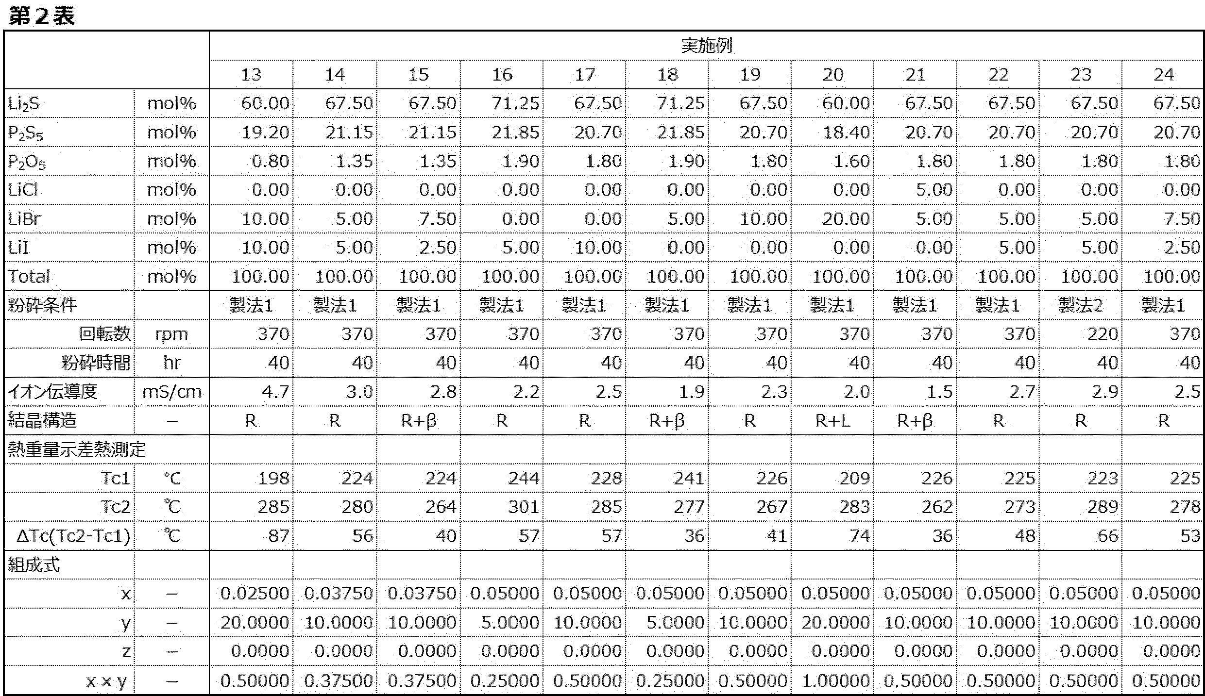
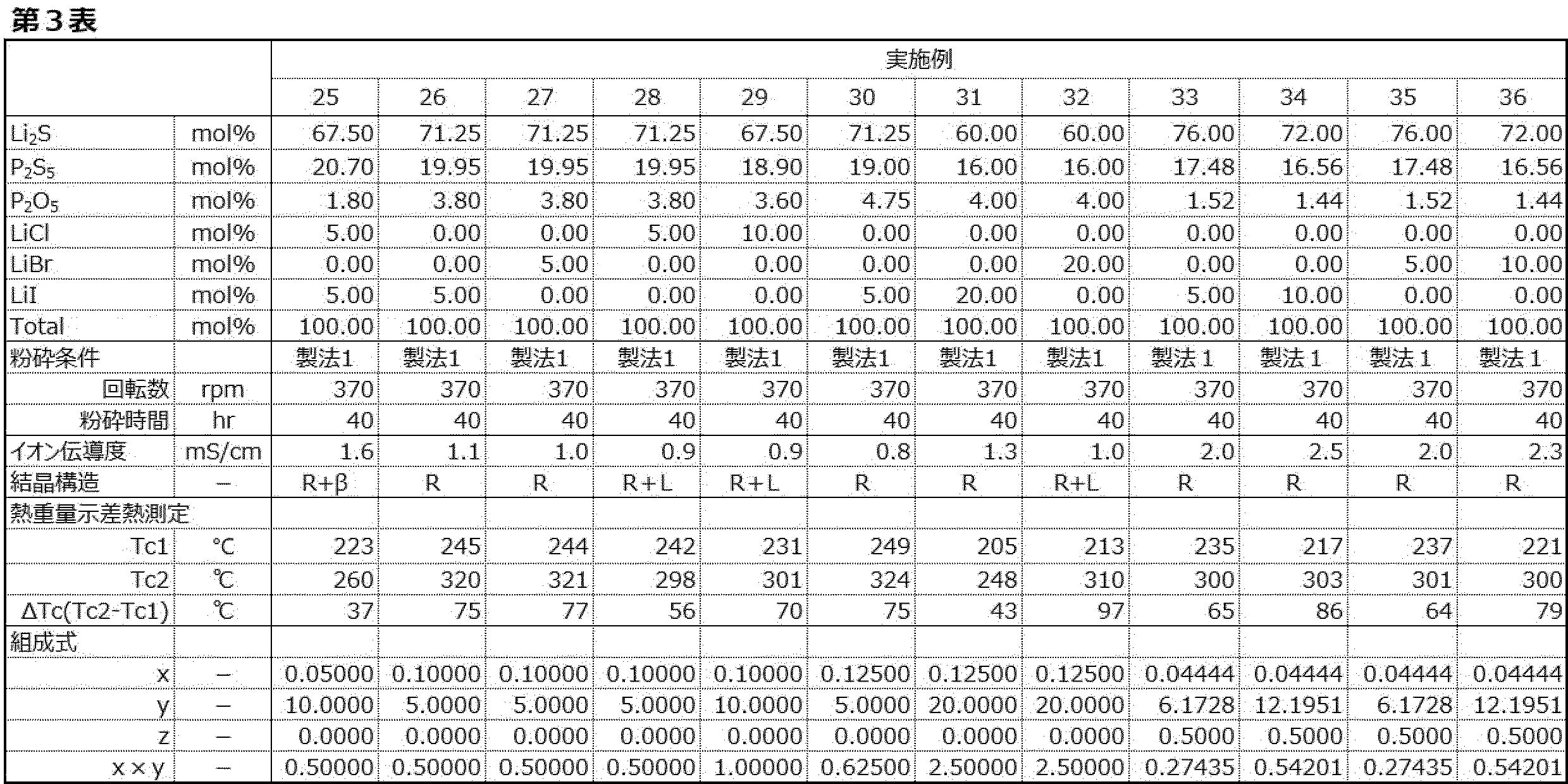
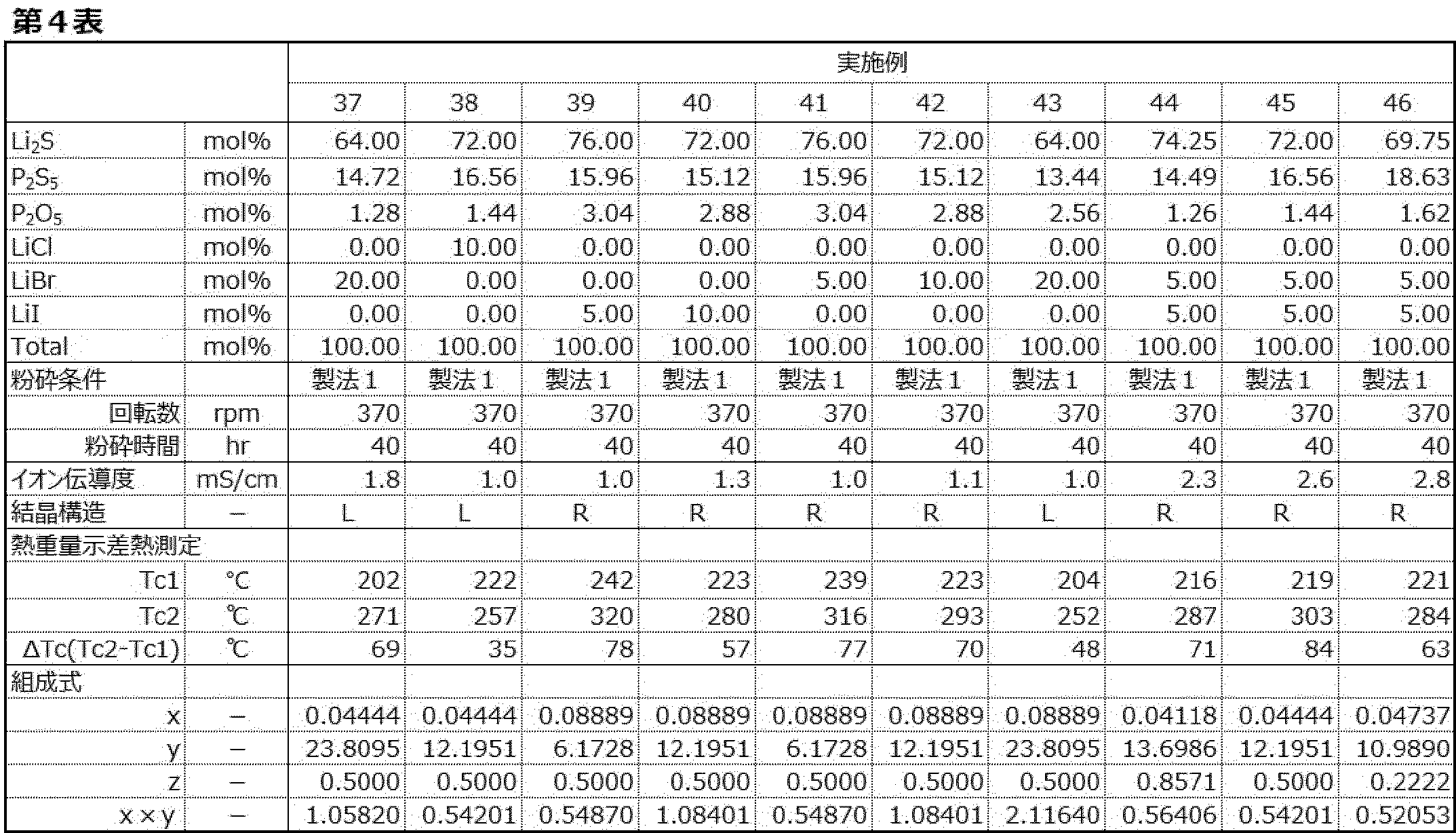
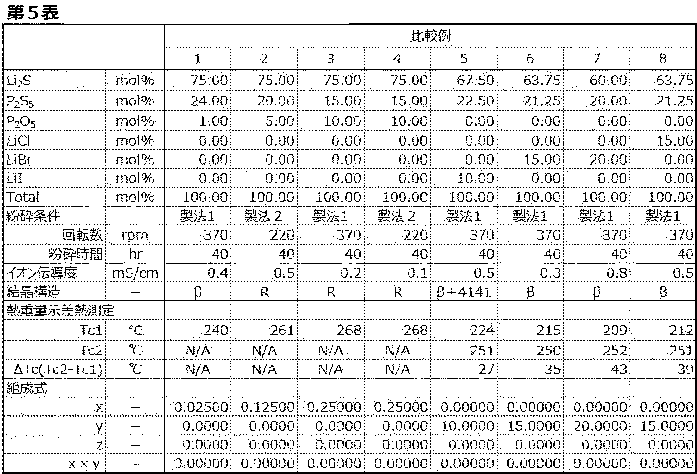
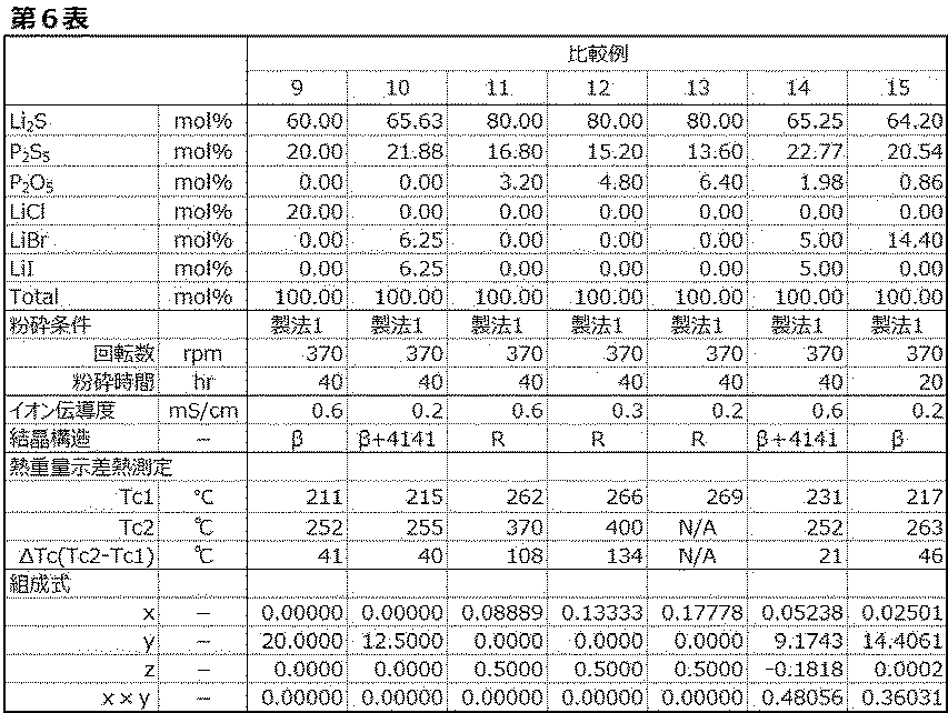
R:主たる結晶構造がチオリシコンリージョンII型結晶構造を有する。
L:主たる結晶構造がLGPS型結晶構造である。
β:主たる結晶構造がβ-Li3PS4(結晶性Li3PS4)である。
R+L:チオリシコンリージョンII型結晶構造及びLGPS型結晶構造の両方を有する。
R+β:チオリシコンリージョンII型結晶構造及びβ-Li3PS4(結晶性Li3PS4)を有する。
β+4141:β-Li3PS4(結晶性Li3PS4)及び結晶性Li4PS4Iを有する。
R+β+4141:チオリシコンリージョンII型結晶構造、β-Li3PS4(結晶性Li3PS4)及び結晶性Li4PS4Iを有する。
製法1:実施例1における粉砕条件であり、原料含有物を合計:1.5gとし、窒素雰囲気下で、直径10mmのジルコニア製ボール10個(約32g)とともにジルコニア製45mlポットに入れ、完全密封し、ポット内を不活性雰囲気下(窒素雰囲気)とし、加熱冷却することなく(室温)、表中に示される回転数及び時間で遊星型ボールミル(フリッチュ社製:型番P-7)でメカニカルミリングを行った。
製法2:製法1において、原料含有物を合計:10gとし、直径10mmのジルコニア製ボールを600g分を、ジルコニア製500mlポットに入れて、粉砕装置として遊星型ボールミル(フリッチュ社製:型番P-5)を用い、表中に示される回転数及び時間とした以外は、製法1と同様にした。
またハロゲン原子を含むものの、酸素原子を含まない比較例5~10の結晶性硫化物固体電解質のうち、比較例5、6及び8~10の結晶性硫化物固体電解質も、実施例の結晶性硫化物固体電解質のイオン伝導度に至らないものとなった。比較例7の結晶性硫化物固体電解質のイオン伝導度は、一部実施例(実施例30)の結晶性硫化物固体電解質と同程度であったものの、ハロゲン原子を含む原料の使用量が多く、原料コストを低減した硫化物固体電解質とはいえないもとなった。
以上の結果から、本実施形態の結晶性硫化物固体電解質は、リチウム原子、硫黄原子、リン原子、酸素原子及びハロゲン原子を含み、かつX線回折測定における特定の回折ピーク及び組成等を有することで、高いイオン伝導度が得られることが確認された。
また、固体31P-NMR測定により得られたデータを用い、各構造に起因するピーク面積をもとに、各構造に含まれるリン比率(mol%)を算出した。具体的には、第7表に示される各構造に起因するピークの合計面積に対する各構造のピークの面積の比率から、各構造に含まれるリン比率(mol%)を算出した。算出した各構造のリン比率(mol%)を第7表に示す。
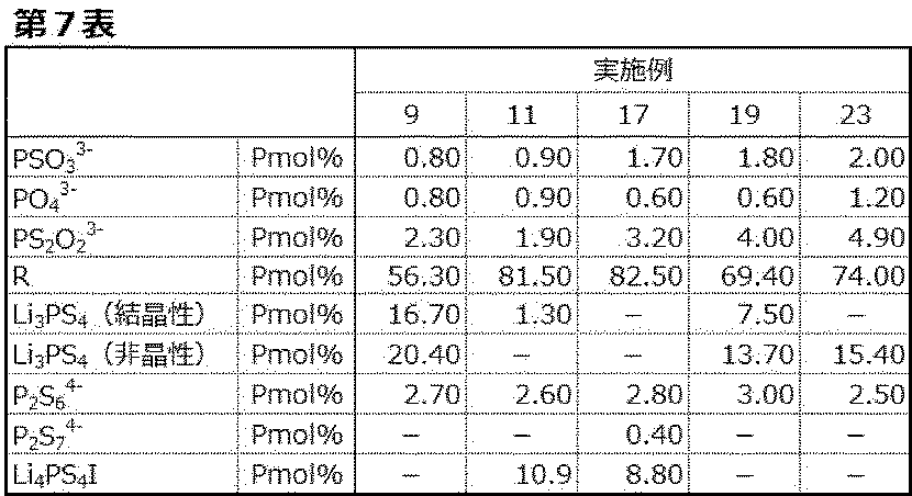
Claims (16)
- リチウム原子、リン原子、硫黄原子、酸素原子及びハロゲン原子を含み、
CuKα線を用いたX線回折測定において、2θ=20.3±0.5°及び29.6±0.6°に回折ピークを有し、
固体31P-NMR測定により39.6±5.0ppmにPSO3 3-に起因するピークが観測され、
かつ下記の組成式(1)で表される組成を有する、
結晶性硫化物固体電解質。
(100-y)(0.5)(Li3+2zP(S1-xOx)4+z)+(y)LiX (1)
(組成式(1)において、x、y及びzは、各々0.00060≦x≦0.15、3.0≦y<25.0、及び-0.17≦z≦1.5を満たす。また、Xはハロゲン原子を示す。) - 前記組成式(1)において、xとyとの積(x×y)が、0.0010以上2.7以下である請求項1に記載の結晶性硫化物固体電解質。
- 固体31P-NMR測定により、9.2±5.0ppmにPO4 3-に起因するピークが観測される請求項1又は2に記載の結晶性硫化物固体電解質。
- 固体31P-NMR測定により、70.3±5.0ppmにPS2O2 3-に起因するピークが観測される請求項1~3のいずれか1項に記載の結晶性硫化物固体電解質。
- 熱重量示差熱測定(昇温速度10℃/分で測定した。)において少なくとも2つの発熱ピークが測定され、前記2つの発熱ピークのピークトップの温度差が、20℃以上110℃以下である請求項1~4のいずれか1項に記載の結晶性硫化物固体電解質。
- 前記ハロゲン原子が、塩素原子、臭素原子及びヨウ素原子から選ばれる少なくとも一種のハロゲン原子である請求項1~5のいずれか1項に記載の結晶性硫化物固体電解質。
- 前記ハロゲン原子が、臭素原子及びヨウ素原子である請求項1~6のいずれか1項に記載の結晶性硫化物固体電解質。
- 前記組成式(1)において、yが14.0<y<25.0を満たす請求項1~7のいずれか1項に記載の結晶性硫化物固体電解質。
- イオン伝導度が、0.85mS/cm以上である請求項1~8のいずれか1項に記載の結晶性硫化物固体電解質。
- イオン伝導度が、2.5mS/cm以上である請求項1~9のいずれか1項に記載の結晶性硫化物固体電解質。
- ナトリウム原子、ホウ素原子、アルミニウム原子、ケイ素原子、ゲルマニウム原子、ヒ素原子、セレン原子、アンチモン原子、テルル原子、鉛原子及びビスマス原子から選ばれる少なくとも一の金属原子を含まない請求項1~10のいずれか1項に記載の結晶性硫化物固体電解質
- 前記酸素原子が、P2O5に由来するものである請求項1~11のいずれか1項に記載の結晶性硫化物固体電解質。
- ガラスセラミックである請求項1~12のいずれか1項に記載の結晶性硫化物固体電解質。
- リチウム原子、リン原子、硫黄原子、酸素原子及びハロゲン原子を含み、
CuKα線を用いたX線回折測定において、2θ=20.3±0.5°及び29.6±0.6°に回折ピークを有し、
固体31P-NMR測定により39.6±5.0ppmにPSO3 3-に起因するピークが観測される、
結晶性硫化物固体電解質。 - 固体31P-NMR測定により、9.2±5.0ppmにPO4 3-に起因するピークが観測される請求項14に記載の結晶性硫化物固体電解質。
- 固体31P-NMR測定により、70.3±5.0ppmにPS2O2 3-に起因するピークが観測される請求項14又は15に記載の結晶性硫化物固体電解質。
Priority Applications (4)
| Application Number | Priority Date | Filing Date | Title |
|---|---|---|---|
| JP2025526080A JPWO2024253019A1 (ja) | 2023-06-09 | 2024-05-30 | |
| EP24819249.4A EP4726742A1 (en) | 2023-06-09 | 2024-05-30 | Crystalline sulfide solid electrolyte |
| KR1020257040542A KR20260020931A (ko) | 2023-06-09 | 2024-05-30 | 결정성 황화물 고체 전해질 |
| CN202480037326.3A CN121336266A (zh) | 2023-06-09 | 2024-05-30 | 结晶性硫化物固体电解质 |
Applications Claiming Priority (2)
| Application Number | Priority Date | Filing Date | Title |
|---|---|---|---|
| JP2023095791 | 2023-06-09 | ||
| JP2023-095791 | 2023-06-09 |
Publications (1)
| Publication Number | Publication Date |
|---|---|
| WO2024253019A1 true WO2024253019A1 (ja) | 2024-12-12 |
Family
ID=93795992
Family Applications (1)
| Application Number | Title | Priority Date | Filing Date |
|---|---|---|---|
| PCT/JP2024/019908 Ceased WO2024253019A1 (ja) | 2023-06-09 | 2024-05-30 | 結晶性硫化物固体電解質 |
Country Status (5)
| Country | Link |
|---|---|
| EP (1) | EP4726742A1 (ja) |
| JP (1) | JPWO2024253019A1 (ja) |
| KR (1) | KR20260020931A (ja) |
| CN (1) | CN121336266A (ja) |
| WO (1) | WO2024253019A1 (ja) |
Citations (5)
| Publication number | Priority date | Publication date | Assignee | Title |
|---|---|---|---|---|
| JP2014089986A (ja) | 2014-02-13 | 2014-05-15 | Toyota Motor Corp | 硫化物固体電解質材料およびリチウム固体電池 |
| JP2014093261A (ja) | 2012-11-06 | 2014-05-19 | Idemitsu Kosan Co Ltd | 固体電解質 |
| JP2014093263A (ja) | 2012-11-06 | 2014-05-19 | Idemitsu Kosan Co Ltd | 固体電解質及びリチウム電池 |
| WO2019207956A1 (ja) * | 2018-04-25 | 2019-10-31 | 国立大学法人東京工業大学 | 硫化物固体電解質および全固体電池 |
| WO2021132173A1 (ja) * | 2019-12-23 | 2021-07-01 | 出光興産株式会社 | 固体電解質の製造方法 |
-
2024
- 2024-05-30 JP JP2025526080A patent/JPWO2024253019A1/ja active Pending
- 2024-05-30 KR KR1020257040542A patent/KR20260020931A/ko active Pending
- 2024-05-30 WO PCT/JP2024/019908 patent/WO2024253019A1/ja not_active Ceased
- 2024-05-30 CN CN202480037326.3A patent/CN121336266A/zh active Pending
- 2024-05-30 EP EP24819249.4A patent/EP4726742A1/en active Pending
Patent Citations (5)
| Publication number | Priority date | Publication date | Assignee | Title |
|---|---|---|---|---|
| JP2014093261A (ja) | 2012-11-06 | 2014-05-19 | Idemitsu Kosan Co Ltd | 固体電解質 |
| JP2014093263A (ja) | 2012-11-06 | 2014-05-19 | Idemitsu Kosan Co Ltd | 固体電解質及びリチウム電池 |
| JP2014089986A (ja) | 2014-02-13 | 2014-05-15 | Toyota Motor Corp | 硫化物固体電解質材料およびリチウム固体電池 |
| WO2019207956A1 (ja) * | 2018-04-25 | 2019-10-31 | 国立大学法人東京工業大学 | 硫化物固体電解質および全固体電池 |
| WO2021132173A1 (ja) * | 2019-12-23 | 2021-07-01 | 出光興産株式会社 | 固体電解質の製造方法 |
Non-Patent Citations (2)
| Title |
|---|
| KANNO ET AL., JOURNAL OF THE ELECTROCHEMICAL SOCIETY, vol. 148, no. 7, 2001, pages A742 - 746 |
| SOLID STATE IONICS, vol. 177, 2006, pages 2721 - 2725 |
Also Published As
| Publication number | Publication date |
|---|---|
| CN121336266A (zh) | 2026-01-13 |
| EP4726742A1 (en) | 2026-04-15 |
| KR20260020931A (ko) | 2026-02-12 |
| JPWO2024253019A1 (ja) | 2024-12-12 |
Similar Documents
| Publication | Publication Date | Title |
|---|---|---|
| JP7818535B2 (ja) | 改質硫化物固体電解質及びその製造方法 | |
| WO2020105737A1 (ja) | 固体電解質の製造方法及び電解質前駆体 | |
| JP7329607B2 (ja) | 固体電解質の製造方法 | |
| JP7324849B2 (ja) | 電極合材及びその製造方法 | |
| JP2023152783A (ja) | 硫化物固体電解質の製造方法 | |
| JP2023152966A (ja) | 硫化物固体電解質、その製造方法、電極合材及びリチウムイオン電池 | |
| JP7744375B2 (ja) | 改質硫化物固体電解質及びその製造方法 | |
| US20240283008A1 (en) | Sulfide solid electrolyte composition, electrode mixture containing same, and method for producing sulfide solid electrolyte composition | |
| JP2023168276A (ja) | 結晶性硫化物固体電解質の製造方法、結晶性硫化物固体電解質、これを含む電極合材及びリチウムイオン電池 | |
| EP4372764A1 (en) | Sulfide solid electrolyte | |
| WO2024253019A1 (ja) | 結晶性硫化物固体電解質 | |
| WO2024253009A1 (ja) | 結晶性硫化物固体電解質 | |
| KR102910792B1 (ko) | 전극 합재 및 그 제조 방법 | |
| WO2025037517A1 (ja) | 結晶性硫化物固体電解質 | |
| JP7751485B2 (ja) | 硫化物固体電解質の製造方法及び電極合材の製造方法 | |
| JP7742365B2 (ja) | 固体電解質の製造方法 | |
| WO2025173702A1 (ja) | 硫化物固体電解質及び硫化物固体電解質の製造方法 | |
| WO2026054035A1 (ja) | 酸硫化物固体電解質の製造方法、酸硫化物固体電解質前駆体及び酸硫化物固体電解質 | |
| JP2023168318A (ja) | 硫化物固体電解質の製造方法及び硫化物固体電解質 | |
| KR20260052940A (ko) | 결정성 황화물 고체 전해질 | |
| WO2025154577A1 (ja) | 固体電解質、これを用いた電極合材及びリチウムイオン電池並びに改質固体電解質の製造方法 | |
| WO2025205560A1 (ja) | 硫化物固体電解質の製造方法 |
Legal Events
| Date | Code | Title | Description |
|---|---|---|---|
| 121 | Ep: the epo has been informed by wipo that ep was designated in this application |
Ref document number: 24819249 Country of ref document: EP Kind code of ref document: A1 |
|
| ENP | Entry into the national phase |
Ref document number: 2025526080 Country of ref document: JP Kind code of ref document: A |
|
| WWE | Wipo information: entry into national phase |
Ref document number: 2025526080 Country of ref document: JP |
|
| WWE | Wipo information: entry into national phase |
Ref document number: 2024819249 Country of ref document: EP |
|
| NENP | Non-entry into the national phase |
Ref country code: DE |
|
| ENP | Entry into the national phase |
Ref document number: 2024819249 Country of ref document: EP Effective date: 20260109 |
|
| ENP | Entry into the national phase |
Ref document number: 2024819249 Country of ref document: EP Effective date: 20260109 |
|
| ENP | Entry into the national phase |
Ref document number: 2024819249 Country of ref document: EP Effective date: 20260109 |
|
| ENP | Entry into the national phase |
Ref document number: 2024819249 Country of ref document: EP Effective date: 20260109 |
|
| ENP | Entry into the national phase |
Ref document number: 2024819249 Country of ref document: EP Effective date: 20260109 |
|
| WWP | Wipo information: published in national office |
Ref document number: 2024819249 Country of ref document: EP |