WO2024252643A1 - 配管接続具及びこれを用いた配管接続方法 - Google Patents
配管接続具及びこれを用いた配管接続方法 Download PDFInfo
- Publication number
- WO2024252643A1 WO2024252643A1 PCT/JP2023/021431 JP2023021431W WO2024252643A1 WO 2024252643 A1 WO2024252643 A1 WO 2024252643A1 JP 2023021431 W JP2023021431 W JP 2023021431W WO 2024252643 A1 WO2024252643 A1 WO 2024252643A1
- Authority
- WO
- WIPO (PCT)
- Prior art keywords
- pipe
- flange
- jig
- connection
- connection portion
- Prior art date
- Legal status (The legal status is an assumption and is not a legal conclusion. Google has not performed a legal analysis and makes no representation as to the accuracy of the status listed.)
- Ceased
Links
Images






Classifications
-
- F—MECHANICAL ENGINEERING; LIGHTING; HEATING; WEAPONS; BLASTING
- F16—ENGINEERING ELEMENTS AND UNITS; GENERAL MEASURES FOR PRODUCING AND MAINTAINING EFFECTIVE FUNCTIONING OF MACHINES OR INSTALLATIONS; THERMAL INSULATION IN GENERAL
- F16L—PIPES; JOINTS OR FITTINGS FOR PIPES; SUPPORTS FOR PIPES, CABLES OR PROTECTIVE TUBING; MEANS FOR THERMAL INSULATION IN GENERAL
- F16L27/00—Adjustable joints; Joints allowing movement
- F16L27/10—Adjustable joints; Joints allowing movement comprising a flexible connection only
-
- F—MECHANICAL ENGINEERING; LIGHTING; HEATING; WEAPONS; BLASTING
- F16—ENGINEERING ELEMENTS AND UNITS; GENERAL MEASURES FOR PRODUCING AND MAINTAINING EFFECTIVE FUNCTIONING OF MACHINES OR INSTALLATIONS; THERMAL INSULATION IN GENERAL
- F16J—PISTONS; CYLINDERS; SEALINGS
- F16J3/00—Diaphragms; Bellows; Bellows pistons
- F16J3/04—Bellows
- F16J3/041—Non-metallic bellows
-
- F—MECHANICAL ENGINEERING; LIGHTING; HEATING; WEAPONS; BLASTING
- F16—ENGINEERING ELEMENTS AND UNITS; GENERAL MEASURES FOR PRODUCING AND MAINTAINING EFFECTIVE FUNCTIONING OF MACHINES OR INSTALLATIONS; THERMAL INSULATION IN GENERAL
- F16J—PISTONS; CYLINDERS; SEALINGS
- F16J15/00—Sealings
- F16J15/02—Sealings between relatively-stationary surfaces
- F16J15/06—Sealings between relatively-stationary surfaces with solid packing compressed between sealing surfaces
- F16J15/10—Sealings between relatively-stationary surfaces with solid packing compressed between sealing surfaces with non-metallic packing
-
- F—MECHANICAL ENGINEERING; LIGHTING; HEATING; WEAPONS; BLASTING
- F16—ENGINEERING ELEMENTS AND UNITS; GENERAL MEASURES FOR PRODUCING AND MAINTAINING EFFECTIVE FUNCTIONING OF MACHINES OR INSTALLATIONS; THERMAL INSULATION IN GENERAL
- F16J—PISTONS; CYLINDERS; SEALINGS
- F16J15/00—Sealings
- F16J15/02—Sealings between relatively-stationary surfaces
- F16J15/06—Sealings between relatively-stationary surfaces with solid packing compressed between sealing surfaces
- F16J15/10—Sealings between relatively-stationary surfaces with solid packing compressed between sealing surfaces with non-metallic packing
- F16J15/12—Sealings between relatively-stationary surfaces with solid packing compressed between sealing surfaces with non-metallic packing with metal reinforcement or covering
- F16J15/121—Sealings between relatively-stationary surfaces with solid packing compressed between sealing surfaces with non-metallic packing with metal reinforcement or covering with metal reinforcement
-
- F—MECHANICAL ENGINEERING; LIGHTING; HEATING; WEAPONS; BLASTING
- F16—ENGINEERING ELEMENTS AND UNITS; GENERAL MEASURES FOR PRODUCING AND MAINTAINING EFFECTIVE FUNCTIONING OF MACHINES OR INSTALLATIONS; THERMAL INSULATION IN GENERAL
- F16J—PISTONS; CYLINDERS; SEALINGS
- F16J3/00—Diaphragms; Bellows; Bellows pistons
- F16J3/04—Bellows
- F16J3/041—Non-metallic bellows
- F16J3/042—Fastening details
-
- F—MECHANICAL ENGINEERING; LIGHTING; HEATING; WEAPONS; BLASTING
- F16—ENGINEERING ELEMENTS AND UNITS; GENERAL MEASURES FOR PRODUCING AND MAINTAINING EFFECTIVE FUNCTIONING OF MACHINES OR INSTALLATIONS; THERMAL INSULATION IN GENERAL
- F16L—PIPES; JOINTS OR FITTINGS FOR PIPES; SUPPORTS FOR PIPES, CABLES OR PROTECTIVE TUBING; MEANS FOR THERMAL INSULATION IN GENERAL
- F16L27/00—Adjustable joints; Joints allowing movement
- F16L27/10—Adjustable joints; Joints allowing movement comprising a flexible connection only
- F16L27/107—Adjustable joints; Joints allowing movement comprising a flexible connection only the ends of the pipe being interconnected by a flexible sleeve
Definitions
- This disclosure relates to a pipe connector and a pipe connection method using the same.
- Pipe connectors are used in a variety of locations in a wide range of machinery fields, including automobiles, general industrial machinery, and construction machinery. For example, in the automobile field, they are used as joints for cooling pipes in electric vehicles, or as joints for turbo units and intercoolers.
- Patent Document 1 JP 2019-007568 A discloses a pipe connection structure that is interposed between two pipe flow paths (4) and (5) and connects the two pipe flow paths by absorbing misalignment between the two pipe flow paths using a tubular member (1) that is formed into a tubular shape from a rubber-like elastic material (see paragraphs 0024-0025 of Patent Document 1).
- the tubular member (1) has a shape in which one end side (11) that is inserted into the open end of one pipe flow path (4) and the other end side (12) that is inserted into the open end of the other pipe flow path (5) are integrally provided via a funnel-shaped bellows portion (see Figures 1, 2, 5, and 6 of Patent Document 1).
- the one end side (11) fits into the inner peripheral surface of one of the piping flow paths (4). Therefore, a one end side seal portion (2) is provided on the outer peripheral surface of the one end side (11) (see paragraphs 0029-0032 of Patent Document 1).
- the one end side seal portion (2) consists of a hard embedded annular member (21) embedded in the one end side (11) and a lip portion (22) formed by bulging out from the outer peripheral surface of the one end side (11).
- the other end (12) fits into the outer peripheral surface of the other piping flow path (5). Therefore, an other end seal portion (3) is provided on the inner peripheral surface of the other end (12).
- the other end seal portion (3) consists of a hard embedded annular member (35) embedded in the other end (12) and a lip portion (36) formed by bulging out from the inner peripheral surface of the other end (12) (see paragraph 0055 and FIG. 5 of Patent Document 1).
- Patent Document 1 JP 2019-007568 A (Patent Document 1) does not mention how to connect the tubular member (1) to the two piping flow paths (4) (5).
- the invention described in Patent Document 1 does not allow for mechanical connection using, for example, a jig, and is presumed to require manual connection. For this reason, it is not expected to provide a strong bond to the two piping flow paths (4) (5), and it is presumed that high sealing performance will not be achieved. Improvements are desired.
- the objective of this disclosure is to achieve high sealing performance for the two pipes that are connected.
- the pipe connector of the present disclosure is interposed between two pipes arranged in series facing each other in the axial direction, and connects the two pipes.
- the pipe connector comprises a rubber elastic body, a first reinforcing ring having a first tubular portion and a first flange having higher rigidity than the elastic body, and a second reinforcing ring having a second tubular portion and an outwardly facing second flange having higher rigidity than the elastic body.
- the elastic body has a cylindrical shape with connection portions at both ends that fit into one of the pipes and the other of the pipes, and a flexible membrane portion integrally provided between the two connection portions, and a seal portion that seals the pipes is integrally provided on the connection portion.
- the first reinforcing ring is embedded in one of the connection portions that fits into one of the pipes, and the second reinforcing ring is embedded in the other connection portion that fits into the other of the pipes.
- the first flange receives the force of the jig in the direction from the other connection part to the one connection part, and the second flange receives the force of the jig in the direction from the one connection part to the other connection part on the outer periphery of the elastic body.
- the first flange is an inward flange that receives the axial force of a jig inserted into the elastic body from the side of the other connection part.
- the first flange is an outward flange that receives the axial force of a jig inserted into the membrane portion from a direction perpendicular to the axial direction.
- One embodiment of the pipe connection method using a pipe connector includes the steps of preparing the pipe connector of the one embodiment described above, inserting a first jig having a diameter that overlaps with the first flange in the axial direction into the inside of the elastic body from the side of the other connection part, pushing the first jig to pressurize the first flange and connect the one pipe and the one connection part while aligning the one pipe and the one connection part to fit together, removing the first jig, inserting an arc-shaped second jig into the membrane part of the elastic body from a direction perpendicular to the axial direction, pressurizing the second flange with the second jig and connecting the other pipe and the other connection part while aligning the other pipe and the other connection part to fit together, and removing the second jig.
- Another embodiment of the pipe connection method using a pipe connector includes the steps of preparing the pipe connector of the other embodiment described above, inserting the arc-shaped jig into the membrane portion in a direction perpendicular to the axial direction, applying pressure to the first flange with the jig while aligning the one pipe and the one connection part to fit together, connecting the one pipe and the one connection part, applying pressure to the second flange with the jig while aligning the other pipe and the other connection part to fit together, connecting the other pipe and the other connection part, and removing the jig.
- a high level of sealing can be achieved for the two connected pipes.
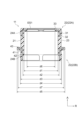
- FIG. 2 is a longitudinal sectional front view showing the pipe connector of the first embodiment.
- FIG. 4 is a longitudinal sectional front view of the pipe connector showing the dimensions of each part.
- 1A to 1E are schematic diagrams showing a longitudinal section of a pipe connector
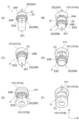
- FIG. 1F is a schematic diagram showing the steps of a pipe connector method in sequence as viewed from the front.
- 5A to 5F are schematic diagrams showing the steps of a pipe connecting method in sequence, as viewed from diagonally below the pipe connector.
- FIG. 4 is a vertical sectional front view showing a modified embodiment of the pipe connector of the first embodiment.
- 13 is a schematic diagram showing a cross-sectional shape of a pipe connector of a second embodiment cut in half at the shaft portion, together with a process of connecting the pipe to the pipe.
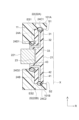
- FIG. 5A is a schematic diagram showing a first example of an embedding position of a reinforcing member
- FIG. 5B is a schematic diagram showing a second example.
- FIG. 13A is a schematic diagram showing a third example of an embedding position of a reinforcing member
- FIG. 13B is a schematic diagram showing a fourth example.
- 13A is a schematic diagram showing a fifth example of the embedding position of the reinforcing member
- FIG. 13B is a schematic diagram showing a sixth example.
- 13A is a schematic diagram showing a first form
- FIG. 13B is a schematic diagram showing a second form
- FIG. 13C is a schematic diagram showing a third form, as shapes of a membrane portion of a pipe connector of a fifth embodiment.
- Pipe connection method using the pipe connector (1) Step of inserting the first jig (2) Step of connecting one pipe to one connection part (3) Step of removing the first jig (4) Step of inserting the second jig (5) Step of connecting the other pipe to the other connection part (6) Step of removing the second jig 3. Function and effect 4.
- Modified form [Third embodiment] 1. Configuration of the pipe connector 2. Pipe connection method using the pipe connector (1) Step of inserting the jig (2) Step of connecting one pipe to one connection part (3) Step of connecting the other pipe to the other connection part (4) Step of removing the jig 3. Function and effect 4. Modified form [Fourth embodiment] 1. Configuration of the pipe connector 2. Pipe connection method using the pipe connector 3.
- a pipe connector 11 of this embodiment is interposed between two pipes 101 arranged in series facing each other in the axial direction, and connects the two pipes 101.
- one of the two pipes 101 will be referred to as pipe 101A, and the other pipe 101 will be referred to as pipe 101B.
- the axis passing through the center of the pipe connector 11 is indicated by the symbol X.
- the axis passing through the center of pipe 101A is indicated by the symbol Y
- the axis passing through the center of pipe 101B is indicated by the symbol Z.
- the symbol A indicates the axial direction
- the symbol R indicates the radial direction perpendicular to the axial direction A.
- the axis Y of the pipe 101A and the axis Z of the pipe 101B do not necessarily have to coincide on the same axis.
- the axes Y and Z may be shifted in parallel or may intersect. Such a state in which the axes Y and Z are shifted can be regarded as the correct position of the two pipes 101 (101A, 101B).
- This embodiment discloses a pipe connector 11 that connects two pipes 101 (101A, 101B) while absorbing unintentional or inherently expected axial misalignment.
- the pipe connector 11 is mainly made of a rubber elastic body 21.
- the elastic body 21 has connection parts 22 at both ends that fit into the end E1 of the pipe 101A and the end E2 of the pipe 101B, respectively, and a flexible membrane part 23 is integrally provided between the two connection parts 22.
- connection part 22A one connection part 22 that connects to the pipe 101A
- connection part 22B the other connection part 22 that connects to the pipe 101B
- a first reinforcing ring 31 made of a material with higher rigidity than the elastic body 21 is embedded in the connection portion 22A.
- the first reinforcing ring 31 has a first cylindrical portion 32 and a first flange 33.
- the first flange 33 is bent at a right angle inward in the radial direction R from the end of the first cylindrical portion 32 that is on the leading side in the fitting direction to the pipe 101A in the axial direction A.
- the elastic body 21 is connected to the pipe 101A by fitting the connection part 22A to the inner peripheral surface of the pipe 101A.
- a seal part 24A is integrally provided on the outer peripheral surface of the connection part 22A.
- a second reinforcing ring 41 made of a material with higher rigidity than the elastic body 21 is embedded in the connection portion 22B.
- the second reinforcing ring 41 has a second tubular portion 42 and a second flange 43.
- the second flange 43 is bent at a right angle from the end of the second tubular portion 42 on the axial direction A, which is on the rear side in the fitting direction to the pipe 101B, toward the outside in the radial direction R.
- the elastic body 21 is connected to the pipe 101B by fitting the connection part 22B to the inner peripheral surface of the pipe 101B.
- a seal part 24B is integrally provided on the outer peripheral surface of the connection part 22B.
- the elastic body 21 is formed from rubber, for example, chloroprene rubber (CR), ethylene propylene rubber (EPDM), acrylic rubber (ACM), or the like.
- CR chloroprene rubber
- EPDM ethylene propylene rubber
- ACM acrylic rubber
- the shape of the elastic body 21 is basically cylindrical, but is not a perfect cylinder.
- connection part 22A side extends inward in the radial direction R.
- the first flange 33 is embedded in this part.
- the first flange 33 and the second flange 43 are covered with the rubber that constitutes the elastic body 21.
- the inner circumferential surface of the elastic body 21 maintains a uniform inner diameter d1 over the entire area. However, on the connection portion 22B side, only the area near the opening has an inner diameter d2 that is slightly larger than the inner diameter d1. The area of the inner diameter d2 is approximately 1/3 of the length of the second tubular portion 42 in the axial direction A.
- the outer diameter of the outer peripheral surface of the elastic body 21 is set to outer diameter d3.
- the two seal portions 24A and 24B, which have the same diameter, have outer diameter d4, which is slightly larger than outer diameter d3.
- the portion of the outer peripheral surface of the elastic body 21 where the second flange 43 is embedded has the maximum outer diameter d5.
- the elastic body 21 has a region where the first reinforcing ring 31 is embedded as the connection portion 22A, a region where the second reinforcing ring 41 is embedded as the connection portion 22B, and a region between the connection portions 22A and 22B as the membrane portion 23.
- the membrane portion 23 is a flexible region made only of rubber, and absorbs axial misalignment that occurs between the connection portions 22A and 22B.
- the elastic body 21 has the sealing portion 24A integrally formed on the outer circumferential surface of the connecting portion 22A, and has the sealing portion 24B integrally formed on the outer circumferential surface of the connecting portion 22B.
- the seal portion 24A protrudes in an annular shape from the outer peripheral surface of the connection portion 22A at a position corresponding to the first tubular portion 32.
- the amount of protrusion is (d4-d3)/2.
- the seal portion 24A and the first reinforcing ring 31 work together to seal the joint between the pipe 101A and the connection portion 22A.
- the seal portion 24A increases the contact pressure against the inner peripheral surface of the pipe 101A to strengthen the sealing action, and at this time the first tubular portion 32 receives the force acting on the seal portion 24A that tries to escape inward in the radial direction R.
- the seal portion 24B protrudes in an annular shape from the outer peripheral surface of the connection portion 22B at a position corresponding to the second tubular portion 42.
- the amount of protrusion is (d4-d3)/2.
- the seal portion 24B and the second reinforcing ring 41 work together to seal the joint between the pipe 101B and the connection portion 22B.
- the seal portion 24B increases the contact pressure against the inner peripheral surface of the pipe 101B to strengthen the sealing action, and at this time the second tubular portion 42 receives the force acting on the seal portion 24B that tries to escape inward in the radial direction R.
- the first reinforcing ring 31 and the second reinforcing ring 41 are ring-shaped members manufactured, for example, by pressing a metal.
- a material such as a synthetic resin, as long as it has a higher rigidity than the elastic body 21 and can increase the bonding strength between the pipe 101 (101A, 101B) and the connection portion 22 (22A, 22B).
- the first tubular portion 32 of the first reinforcing ring 31 and the second tubular portion 42 of the second reinforcing ring 41 both have a cylindrical shape with a diameter slightly larger than the inner diameter d2 of the larger diameter of the elastic body 21.
- the first tubular portion 32 and the second tubular portion 42 have the same diameter.
- the first flange 33 of the first reinforcing ring 31 is an inward flange with an opening in the center.
- the diameter of the opening i.e., the inner diameter d6 of the first flange 33, is smaller than the smaller inner diameter d1 of the elastic body 21. Therefore, when the connection part 22A is viewed from the side of the connection part 22B, the first flange 33 extends radially inward in the R beyond the inner wall of the elastic body 21.
- the second flange 43 of the second reinforcing ring 41 is an outward flange.
- the outer diameter d7 of the second flange 43 is larger than the outer diameter d4 of the two seal portions 24A and 24B. Therefore, when the connection portion 22A is viewed from the connection portion 22B side, the second flange 43 extends radially outward in the R further than the two seal portions 24A and 24B.
- connection portions 22 (22A, 22B) of the elastic body 21 are fitted to the inner periphery of the two pipes 101 (101A, 101B), respectively.
- the two pipes 101 (101A, 101B) have the same inner diameter. Therefore, the diameter of the fitting portion of the connection part 22A to the pipe 101A is the same as the diameter of the fitting portion of the connection part 22B to the pipe 101B.
- the inner diameter of the pipe 101A is the same as or slightly smaller than the outer diameter d3 of the elastic body 21.
- the inner diameter of the pipe 101B is also the same as or slightly smaller than the outer diameter d3 of the elastic body 21. Therefore, when the two connection parts 22 (22A, 22B) are fitted to the two pipes 101 (101A, 101B), respectively, the seal parts 24A and 24B are crushed.
- the end E1 of the pipe 101A has a step S1 formed inside.
- the end face ES1 of the connection part 22A that is fitted into the pipe 101A abuts against the step S1.
- the end E2 of the pipe 101B has a step S2 formed therein.
- the end face ES2 of the connection part 22B that is fitted into the pipe 101B abuts against the step S2.
- the first jig 201 is a cylindrical member having an outer diameter slightly smaller than the inner diameter d1 of the elastic body 21 and larger than the inner diameter d6 of the first flange 33. In other words, the first jig 201 has a diameter that overlaps with the first flange 33 in the axial direction A.
- the first jig 201 is inserted into the elastic body 21 from the side of the connection portion 22B.
- the first jig 201 abuts against the rubber covering the first flange 33.
- the first flange 33 receives the force of the first jig 201 in the direction from the connection portion 22B toward the connection portion 22A.
- the pipe 101A may be pressed against the first jig 201 inserted inside the elastic body 21 while the pipe 101A and the connection portion 22A of the elastic body 21 are aligned so as to fit together.
- the pipe 101A and the connection portion 22A are connected.
- the seal portion 24A is crushed and the pipe 101A and the connection portion 22A are sealed.
- the second jig 211 is an arc-shaped member as if it were a cylindrical member cut in the axial direction.
- the axial thickness of the second jig 211 is set to be narrower than the distance between the end E1 of the pipe 101A connected to the connection part 22A and the rubber part of the elastic body 21 that covers the second flange 43.
- the second jig 211 is inserted into the membrane portion 23 of the elastic body 21 from a direction perpendicular to the axial direction A (radial direction R).
- the arc-shaped inner wall portion of the second jig 211 is inserted into the membrane portion 23.
- the pipe 101B may be pressed against the second jig 211 attached to the membrane portion 23.
- the step portion S2 of the pipe 101B hits the end surface ES2 of the connection portion 22B, the pipe 101B and the connection portion 22B are connected.
- the seal portion 24B is crushed at this time, sealing the pipe 101B and the connection portion 22B.
- the pipe 101A is connected to the connection part 22A
- the pipe 101B is connected to the connection part 22B
- the two pipes 101 (101A, 101B) are connected by the pipe connector 11.
- a first jig 201 is used to connect the pipe 101A to the connection portion 22A
- a second jig 211 is used to connect the pipe 101B to the connection portion 22B. Therefore, the two pipes 101 (101A, 101B) and the two connection portions 22 (22A, 22B) can be connected by press-fitting using a machine. This increases the tightening between the two pipes 101 (101A, 101B) and the two connection portions 22 (22A, 22B), making it possible to connect the two pipes with a large bonding force. As a result, a high sealing performance can be obtained for the two pipes 101 (101A, 101B) to be connected.
- the membrane portion 23 provided on the elastic body 21 has flexibility, and therefore absorbs the axial misalignment that occurs between the two pipes 101 (101A, 101B). Therefore, the pipe connector 11 of this embodiment can follow the static or dynamic eccentricity between the two pipes 101 (101A, 101B).
- FIG 5 is a vertical sectional front view showing a modified embodiment of the pipe connector 11 of the first embodiment.
- sealing portion 24A and 24B This embodiment is a variation of the sealing portion.
- the elastic body 21 of this embodiment has three types of sealing portions 24C1, 24C2, and 24D2.
- sealing portions 24C1, 24C2, and 24D2 are shown diagrammatically with circular symbols indicating their positions.
- the seal portion 24C1 is provided in an annular shape on the end surface ES1 of the connection portion 22A at a position that coincides with the first cylindrical portion 32 of the first reinforcing ring 31 in the axial direction.
- the seal portion 24C1 abuts against a step portion S1 provided in the end portion E1 of the pipe 101A, sealing between the pipe 101A and the connection portion 22A.
- the seal portion 24C2 is provided in an annular shape on the end surface ES2 of the connection portion 22B at a position that coincides with the second cylindrical portion 42 of the second reinforcing ring 41 in the axial direction.
- the seal portion 24C2 abuts against a step portion S2 provided in the end portion E2 of the pipe 101B, sealing between the pipe 101B and the connection portion 22B.
- the seal portion 24D2 is provided in an annular shape on the rubber of the elastic body 21 that covers the second flange 43, at the portion that faces the pipe 101B.
- the seal portion 24D2 abuts against the end E2 of the pipe 101B, sealing between the pipe 101B and the connection portion 22B.
- the first reinforcing ring 31 has a first flange 33 at the end of the first cylindrical portion 32, which is on the rear side in the fitting direction to the pipe 101A.
- the first jig 201 has a diameter that overlaps with the first flange 33 in the axial direction A. Therefore, when the first jig 201 is inserted inside the elastic body 21, it abuts against the rubber that covers the first flange 33. The first flange 33 receives the force of the first jig 201 in the direction from the connection portion 22B toward the connection portion 22A.
- the pipe 101A may be pressed against the first jig 201 inserted inside the elastic body 21 while the pipe 101A and the connection portion 22A of the elastic body 21 are aligned to fit together. In this case, when the step portion S1 of the pipe 101A hits the end surface ES1 of the connection portion 22A, the pipe 101A and the connection portion 22A are connected.
- the seal portion 24A is crushed and the pipe 101A and the connection portion 22A are sealed.
- the second jig 211 is a member having an arc shape as if a cylindrical member had been cut in the axial direction (see Figures 4(D) to (F) showing the first embodiment).
- the second jig 211 is inserted into the membrane portion 23 of the elastic body 21 from a direction perpendicular to the axial direction A (radial direction R).
- the arc-shaped inner wall portion of the second jig 211 is inserted into the membrane portion 23.
- the pipe 101B may be pressed against the second jig 211 attached to the membrane portion 23.
- the step portion S2 of the pipe 101B hits the end surface ES2 of the connection portion 22B, the pipe 101B and the connection portion 22B are connected.
- the seal portion 24B is crushed at this time, sealing the pipe 101B and the connection portion 22B.
- the pipe 101A is connected to the connection part 22A
- the pipe 101B is connected to the connection part 22B
- the two pipes 101 (101A, 101B) are connected by the pipe connector 11.
- FIG. 7 is a vertical sectional front view showing a modified embodiment of the pipe connector 11 of the second embodiment.
- sealing portion 24C1, 24C2, and 24D1 are shown diagrammatically with circular symbols indicating their positions.
- the seal portion 24C1 is provided in an annular shape on the end surface ES1 of the connection portion 22A at a position that coincides with the first cylindrical portion 32 of the first reinforcing ring 31 in the axial direction.
- the seal portion 24C1 abuts against a step portion S1 provided in the end portion E1 of the pipe 101A, sealing between the pipe 101A and the connection portion 22A.
- the seal portion 24C2 is provided in an annular shape on the end surface ES2 of the connection portion 22B at a position that coincides with the second cylindrical portion 42 of the second reinforcing ring 41 in the axial direction.
- the seal portion 24C2 abuts against a step portion S2 provided in the end portion E2 of the pipe 101B, sealing between the pipe 101B and the connection portion 22B.
- the seal portion 24D1 is provided in an annular shape on the rubber of the elastic body 21 that covers the first flange 33, at the portion that faces the pipe 101A.
- the seal portion 24D1 abuts against the end E1 of the pipe 101A, sealing between the pipe 101A and the connection portion 22A.
- the first reinforcing ring 31 has a first flange 33 at the end of the first cylindrical portion 32, which is on the rear side in the fitting direction to the pipe 101A. In this respect, it differs from the first embodiment, but is common to the second embodiment. However, unlike the second embodiment, the first flange 33 is an outward flange. Because the first flange 33 is an outward flange, the first flange 33 and the second flange 43 face each other with the membrane portion 23 sandwiched between them.
- the jig 221 is an arc-shaped member as if it were a cylindrical member cut in the axial direction.
- the axial thickness of the jig 221 is set to be narrower than the distance between the first flange 33 and the second flange 43, which face each other via the membrane portion 23.
- the jig 221 has a diameter that overlaps with the first flange 33 and the second flange 43 in the axial direction A.
- the jig 221 is inserted into the membrane portion 23 of the elastic body 21 from a direction perpendicular to the axial direction A (radial direction R).
- the part that is inserted into the membrane portion 23 is the arc-shaped inner wall portion of the jig 221.
- the pipe 101A may be pressed against the jig 221 attached to the membrane portion 23 while the pipe 101A and the connection portion 22A of the elastic body 21 are aligned so as to fit together.
- the pipe 101A and the connection portion 22A are connected.
- the seal portion 24A is crushed and the pipe 101A and the connection portion 22A are sealed.
- the pipe 101B may be pressed against the jig 221 attached to the membrane part 23 while the pipe 101B and the connection part 22B are aligned so that they fit together.
- the pipe 101B and the connection part 22B are connected.
- the seal portion 24B is crushed at this time, sealing the pipe 101B and the connection portion 22B.
- the pipe 101A is connected to the connection part 22A
- the pipe 101B is connected to the connection part 22B
- the two pipes 101 (101A, 101B) are connected by the pipe connector 11.
- the jig 221 is attached to the membrane portion 23 of the elastic body 21, and this single jig 221 can support both the connection work between the pipe 101A and the connection portion 22A and the connection work between the pipe 101B and the connection portion 22B. Therefore, by using the single jig 221 for both, the pipe connection method can be performed with a small number of steps, and the work efficiency can be improved.
- this embodiment has the same effects as the first and second embodiments.
- Fig. 9 is a vertical sectional front view showing a modified form of the pipe connector 11 of the third embodiment.
- sealing portion 24C1, 24C2, 24D1, and 24D2 are shown diagrammatically with circular symbols indicating their positions.
- the seal portion 24C1 is provided in an annular shape on the end surface ES1 of the connection portion 22A at a position that coincides with the first cylindrical portion 32 of the first reinforcing ring 31 in the axial direction.
- the seal portion 24C1 abuts against a step portion S1 provided in the end portion E1 of the pipe 101A, sealing between the pipe 101A and the connection portion 22A.
- the seal portion 24C2 is provided in an annular shape on the end surface ES2 of the connection portion 22B at a position that coincides with the second cylindrical portion 42 of the second reinforcing ring 41 in the axial direction.
- the seal portion 24C2 abuts against a step portion S2 provided in the end portion E2 of the pipe 101B, sealing between the pipe 101B and the connection portion 22B.
- the seal portion 24D1 is provided in an annular shape on the rubber of the elastic body 21 that covers the first flange 33, at the portion that faces the pipe 101A.
- the seal portion 24D1 abuts against the end E1 of the pipe 101A, sealing between the pipe 101A and the connection portion 22A.
- the seal portion 24D2 is provided in an annular shape on the rubber of the elastic body 21 that covers the second flange 43, at the portion that faces the pipe 101B.
- the seal portion 24D2 abuts against the end E2 of the pipe 101B, sealing between the pipe 101B and the connection portion 22B.
- a reinforcing member 51 is embedded in the membrane portion 23 of the elastic body 21.
- the reinforcing member 51 has a structure capable of increasing the rigidity of the membrane portion 23, and for example, a coil spring 52, a base fabric 53, or the like can be used as the reinforcing member 51.
- the coil spring 52 is made of elastic linear material wound in a spiral shape, and matches the cylindrical shape of the membrane portion 23, making it easy to embed within the cylindrical shape of the membrane portion 23.
- the coil spring 52 expands and contracts in the axial direction A, and also elastically deforms in both the axial direction A and the radial direction R, increasing the rigidity of the membrane portion 23 when embedded within the membrane portion 23.
- the base fabric 53 is a fabric product made by intertwining warp threads and weft threads, with the weft threads woven between the warp threads that cross vertically. Due to its nature, the base fabric 53 is flexible, so it can be embedded in the membrane portion 23 to fit the cylindrical shape of the membrane portion 23. The embedded base fabric 53 suppresses deformation of the membrane portion 23 and increases its rigidity.
- a reinforcing member 51 such as a coil spring 52 or a base fabric 53 can be embedded in the membrane portion 23 at a position on the axial direction A passing through the first tubular portion 32 and the second tubular portion 42.
- the reinforcing member 51 may be arranged so as to be in a non-contact state with the first tubular portion 32 and the second tubular portion 42 (see Figure 11(A)), or may be arranged so as to be in contact with the first tubular portion 32 and the second tubular portion 42 (see Figure 11(B)).
- reinforcing members 51 such as coil springs 52 and base fabric 53 can be embedded in the membrane portion 23 along the axial direction A on the inner periphery side of the first tubular portion 32 and the second tubular portion 42.
- the reinforcing members 51 may be arranged so as to be in a non-contact state with the first tubular portion 32 and the second tubular portion 42 (see Figure 12(A)), or may be arranged so as to be in contact with the first tubular portion 32 and the second tubular portion 42 (see Figure 12(B)).
- the configuration example shown in Figures 13(A) and (B) is an example in which a base cloth 53 is used as the reinforcing member 51.
- the base cloth 53 is embedded in the membrane portion 23 so that one end side is on the outer periphery side of the first tubular portion 32 and the other end side is on the inner periphery side of the second tubular portion 42.
- the base cloth 53 may be arranged so as to be in a non-contact state with the first tubular portion 32 and the second tubular portion 42 (see Figure 13(A)), or may be arranged so as to be in contact with the first tubular portion 32 and the second tubular portion 42 (see Figure 13(B)).
- one end of the base fabric 53 may be on the inner periphery of the first tubular portion 32 and the other end on the outer periphery of the second tubular portion 42.
- the base fabric 53 may be arranged either in a non-contact state with the first tubular portion 32 and the second tubular portion 42 or in a contact state with them.
- FIGS. 10 to 13 show a configuration example in which a reinforcing member 51 is embedded in the membrane portion 23 of the pipe connector 11 of the first embodiment.
- the object in which the reinforcing member 51 is embedded in the membrane portion 23 is not limited to the first embodiment, and may be the pipe connector 11 of the second embodiment or the third embodiment.
- connection direction of the two pipes 101 (101A, 101B) using this follows the pipe connection method of the first embodiment illustrated in Figures 3 and 4.
- connection direction of the two pipes 101 (101A, 101B) using this follows the pipe connection method of the second embodiment illustrated in FIG. 6.
- connection direction of the two pipes 101 (101A, 101B) using this follows the pipe connection method of the third embodiment illustrated in FIG. 8.
- the reinforcing member 51 can also generate a restraining force against buckling of the membrane portion 23. Therefore, even if an excessive force that would cause buckling is applied to the membrane portion 23 during the work of connecting the connection portions 22 (22A, 22B) of the pipe connector 11 to the pipes 101 (101A, 101B), the membrane portion 23 can be protected from buckling.
- the reinforcing member 51 also increases the tensile strength of the membrane portion 23. For example, when the connection portion 22 (22A, 22B) of the pipe connector 11 is removed from the pipe 101 (101A, 101B) for maintenance or the like, even if an excessive tensile force that could cause damage is applied to the membrane portion 23, the membrane portion 23 can be protected from damage.
- the elasticity of the base fabric 53 can be changed by changing the mesh size, which varies depending on how the warp and weft threads are entangled, and the material of the warp and weft threads.
- the eccentricity tracking ability of the membrane portion 23 can be adjusted by the elasticity of the base fabric 53.
- the membrane portion 23 in the first to fourth embodiments has a straight shape along the axial direction A.
- the membrane portion 23 in the present embodiment has a curved shape when viewed in cross section. Three shapes of the curved membrane portion 23 are introduced.
- FIG. 14(A) is a schematic diagram showing an elastic body 21 having a first type of membrane portion 23.
- the membrane portion 23 has a central portion that is curved and has a smaller diameter than both end portions.
- FIG. 14(B) is a schematic diagram showing an elastic body 21 having a second type of membrane portion 23.
- the membrane portion 23 has a barrel shape with a curved central portion, and the central portion has a larger diameter than both end portions.
- FIG. 14(C) is a schematic diagram showing an elastic body 21 having a membrane portion 23 of a third form.
- the membrane portion 23 has a bellows shape that expands and contracts in the axial direction.
- the membrane portion 23 of the first to third embodiments all have a bent shape when viewed in cross section, and therefore is easily bent in both the axial direction A and the radial direction R. This makes it possible to improve the eccentricity tracking ability of the two pipes 101 (101A, 101B) connected by the pipe connector 11 in both the axial direction A and the radial direction R.
- Pipe connector 21 Elastic body 22 Connection part 22A Connection part (one connection part) 22B Connection part (other connection part) 23 Membrane portion 24A Sealed portion 24B Sealed portion 24C1 Sealed portion 24C2 Sealed portion 24D1 Sealed portion 24D2 Sealed portion 31 First reinforcing ring 32 First tubular portion 33 First flange 41 Second reinforcing ring 42 Second tubular portion 43 Second flange 51 Reinforcing member 52 Coil spring 53 Foundation fabric 101 Pipe 101A Pipe (one of the pipes) 101B Piping (other piping) 201 First jig 211 Second jig 221 Jig d1, d2, d6 Inner diameter d3 to d5, d7 Outer diameter A Axial direction E1 End E2 End ES1 End face ES2 End face R Radial direction S1 Step S2 Step X Axis passing through the center of the pipe connector Y Axis passing through the center of one pipe Z Axis passing through the center of the other pipe
Landscapes
- Engineering & Computer Science (AREA)
- General Engineering & Computer Science (AREA)
- Mechanical Engineering (AREA)
- Quick-Acting Or Multi-Walled Pipe Joints (AREA)
- Joints Allowing Movement (AREA)
Priority Applications (6)
| Application Number | Priority Date | Filing Date | Title |
|---|---|---|---|
| EP23940741.4A EP4726244A1 (en) | 2023-06-08 | 2023-06-08 | Pipe connection tool and pipe connection method using same |
| PCT/JP2023/021431 WO2024252643A1 (ja) | 2023-06-08 | 2023-06-08 | 配管接続具及びこれを用いた配管接続方法 |
| JP2025525888A JPWO2024252643A1 (https=) | 2023-06-08 | 2023-06-08 | |
| KR1020257034055A KR20250168318A (ko) | 2023-06-08 | 2023-06-08 | 배관 접속구 및 이를 이용한 배관 접속 방법 |
| CN202380097443.4A CN121002318A (zh) | 2023-06-08 | 2023-06-08 | 配管连接用具和使用了该配管连接用具的配管连接方法 |
| TW112146473A TWI900952B (zh) | 2023-06-08 | 2023-11-30 | 配管連接具及使用該配管連接具的配管連接方法 |
Applications Claiming Priority (1)
| Application Number | Priority Date | Filing Date | Title |
|---|---|---|---|
| PCT/JP2023/021431 WO2024252643A1 (ja) | 2023-06-08 | 2023-06-08 | 配管接続具及びこれを用いた配管接続方法 |
Publications (1)
| Publication Number | Publication Date |
|---|---|
| WO2024252643A1 true WO2024252643A1 (ja) | 2024-12-12 |
Family
ID=93795688
Family Applications (1)
| Application Number | Title | Priority Date | Filing Date |
|---|---|---|---|
| PCT/JP2023/021431 Ceased WO2024252643A1 (ja) | 2023-06-08 | 2023-06-08 | 配管接続具及びこれを用いた配管接続方法 |
Country Status (6)
| Country | Link |
|---|---|
| EP (1) | EP4726244A1 (https=) |
| JP (1) | JPWO2024252643A1 (https=) |
| KR (1) | KR20250168318A (https=) |
| CN (1) | CN121002318A (https=) |
| TW (1) | TWI900952B (https=) |
| WO (1) | WO2024252643A1 (https=) |
Citations (6)
| Publication number | Priority date | Publication date | Assignee | Title |
|---|---|---|---|---|
| JPS4948229U (https=) * | 1972-08-01 | 1974-04-26 | ||
| JPS60169486U (ja) * | 1984-04-19 | 1985-11-09 | 株式会社 栗本鉄工所 | 管継手 |
| JPS63171648U (https=) * | 1987-04-30 | 1988-11-08 | ||
| DE19548249A1 (de) * | 1995-12-22 | 1997-06-26 | Freudenberg Carl Fa | Steckstück |
| JP2015227701A (ja) * | 2014-06-02 | 2015-12-17 | 内山工業株式会社 | 配管接続構造及び接続部材 |
| JP2019007568A (ja) | 2017-06-26 | 2019-01-17 | Nok株式会社 | 配管接続構造 |
Family Cites Families (6)
| Publication number | Priority date | Publication date | Assignee | Title |
|---|---|---|---|---|
| US7845686B2 (en) * | 2007-12-17 | 2010-12-07 | S & B Technical Products, Inc. | Restrained pipe joining system for plastic pipe |
| CN206386596U (zh) * | 2016-08-23 | 2017-08-08 | 河南华威供水材料有限公司 | 一种带有金属加强环可曲挠橡胶接头 |
| KR101972900B1 (ko) | 2017-07-12 | 2019-04-30 | 한국에너지기술연구원 | 작물재배장치 |
| CN109084108A (zh) * | 2018-10-18 | 2018-12-25 | 青岛万合美联电器服务有限责任公司 | 便捷插接的快速接头结构 |
| CN216923535U (zh) * | 2022-02-22 | 2022-07-08 | 安耐特流体输送科技有限公司 | 管道连接用密封圈及管道密封连接器 |
| CN218761969U (zh) * | 2022-12-10 | 2023-03-28 | 肖素军 | 一种管道连接装置 |
-
2023
- 2023-06-08 EP EP23940741.4A patent/EP4726244A1/en active Pending
- 2023-06-08 JP JP2025525888A patent/JPWO2024252643A1/ja active Pending
- 2023-06-08 CN CN202380097443.4A patent/CN121002318A/zh active Pending
- 2023-06-08 WO PCT/JP2023/021431 patent/WO2024252643A1/ja not_active Ceased
- 2023-06-08 KR KR1020257034055A patent/KR20250168318A/ko active Pending
- 2023-11-30 TW TW112146473A patent/TWI900952B/zh active
Patent Citations (6)
| Publication number | Priority date | Publication date | Assignee | Title |
|---|---|---|---|---|
| JPS4948229U (https=) * | 1972-08-01 | 1974-04-26 | ||
| JPS60169486U (ja) * | 1984-04-19 | 1985-11-09 | 株式会社 栗本鉄工所 | 管継手 |
| JPS63171648U (https=) * | 1987-04-30 | 1988-11-08 | ||
| DE19548249A1 (de) * | 1995-12-22 | 1997-06-26 | Freudenberg Carl Fa | Steckstück |
| JP2015227701A (ja) * | 2014-06-02 | 2015-12-17 | 内山工業株式会社 | 配管接続構造及び接続部材 |
| JP2019007568A (ja) | 2017-06-26 | 2019-01-17 | Nok株式会社 | 配管接続構造 |
Non-Patent Citations (1)
| Title |
|---|
| See also references of EP4726244A1 |
Also Published As
| Publication number | Publication date |
|---|---|
| KR20250168318A (ko) | 2025-12-02 |
| TWI900952B (zh) | 2025-10-11 |
| TW202449316A (zh) | 2024-12-16 |
| EP4726244A1 (en) | 2026-04-15 |
| JPWO2024252643A1 (https=) | 2024-12-12 |
| CN121002318A (zh) | 2025-11-21 |
Similar Documents
| Publication | Publication Date | Title |
|---|---|---|
| EP2143981B1 (en) | Gasket for providing a seal between two objects | |
| US4204707A (en) | Vibration absorbing connector | |
| JP2000274562A (ja) | 積層コルゲートチューブ | |
| JP4089409B2 (ja) | 燃料ホース、燃料ホース接続方法及び燃料ホース接続構造体 | |
| JPH09236187A (ja) | ホースとその製造方法 | |
| WO2024252643A1 (ja) | 配管接続具及びこれを用いた配管接続方法 | |
| JP3210602U (ja) | 小径配管用継手 | |
| CN112639314B (zh) | 轴承组装体、轴承组装体的制造方法以及传动轴的制造方法 | |
| JP2850700B2 (ja) | ホース | |
| JP2001159478A (ja) | 可とう伸縮管及び可とう伸縮継手 | |
| US4240653A (en) | Flexible expansion joint | |
| JP5684516B2 (ja) | 可撓継手 | |
| CN211693973U (zh) | 一种膨胀活接 | |
| US12135107B2 (en) | Pipe replacement system | |
| WO1997018408A2 (en) | Sandwich bellows construction | |
| JPH074236A (ja) | 自動車排気管系のフランジ継手構造 | |
| US7431344B2 (en) | Connection assembly and related method | |
| CN219493448U (zh) | 一种钢圈加强型橡胶波纹管 | |
| JPH01126488A (ja) | 可撓性管継手 | |
| WO2025120894A1 (ja) | 流体圧アクチュエータ及び流体圧アクチュエータの製造方法 | |
| WO2025126869A1 (ja) | 流体圧アクチュエータ | |
| US20240175532A1 (en) | Expansion joint with arch geometry | |
| JP4448985B2 (ja) | 硬質相手パイプ・ホースと樹脂ホースのシール接続構造 | |
| JP2024084596A (ja) | 流体圧アクチュエータ | |
| WO2024232114A1 (ja) | 流体圧アクチュエータ |
Legal Events
| Date | Code | Title | Description |
|---|---|---|---|
| 121 | Ep: the epo has been informed by wipo that ep was designated in this application |
Ref document number: 23940741 Country of ref document: EP Kind code of ref document: A1 |
|
| ENP | Entry into the national phase |
Ref document number: 2025525888 Country of ref document: JP Kind code of ref document: A |
|
| WWE | Wipo information: entry into national phase |
Ref document number: 2025525888 Country of ref document: JP |
|
| ENP | Entry into the national phase |
Ref document number: 1020257034055 Country of ref document: KR Free format text: ST27 STATUS EVENT CODE: A-0-1-A10-A15-NAP-PA0105 (AS PROVIDED BY THE NATIONAL OFFICE) |
|
| WWE | Wipo information: entry into national phase |
Ref document number: KR1020257034055 Country of ref document: KR Ref document number: 2501006992 Country of ref document: TH Ref document number: 1020257034055 Country of ref document: KR |
|
| WWP | Wipo information: published in national office |
Ref document number: 1020257034055 Country of ref document: KR |
|
| WWE | Wipo information: entry into national phase |
Ref document number: 2023940741 Country of ref document: EP |
|
| NENP | Non-entry into the national phase |
Ref country code: DE |
|
| ENP | Entry into the national phase |
Ref document number: 2023940741 Country of ref document: EP Effective date: 20260108 |
|
| ENP | Entry into the national phase |
Ref document number: 2023940741 Country of ref document: EP Effective date: 20260108 |
|
| ENP | Entry into the national phase |
Ref document number: 2023940741 Country of ref document: EP Effective date: 20260108 |
|
| ENP | Entry into the national phase |
Ref document number: 2023940741 Country of ref document: EP Effective date: 20260108 |
|
| ENP | Entry into the national phase |
Ref document number: 2023940741 Country of ref document: EP Effective date: 20260108 |
|
| WWP | Wipo information: published in national office |
Ref document number: 2023940741 Country of ref document: EP |