WO2024252614A1 - 運転支援装置および運転支援方法 - Google Patents
運転支援装置および運転支援方法 Download PDFInfo
- Publication number
- WO2024252614A1 WO2024252614A1 PCT/JP2023/021342 JP2023021342W WO2024252614A1 WO 2024252614 A1 WO2024252614 A1 WO 2024252614A1 JP 2023021342 W JP2023021342 W JP 2023021342W WO 2024252614 A1 WO2024252614 A1 WO 2024252614A1
- Authority
- WO
- WIPO (PCT)
- Prior art keywords
- road
- illumination
- driving assistance
- vehicle
- assistance device
- Prior art date
- Legal status (The legal status is an assumption and is not a legal conclusion. Google has not performed a legal analysis and makes no representation as to the accuracy of the status listed.)
- Ceased
Links
Images





Classifications
-
- B—PERFORMING OPERATIONS; TRANSPORTING
- B60—VEHICLES IN GENERAL
- B60Q—ARRANGEMENT OF SIGNALLING OR LIGHTING DEVICES, THE MOUNTING OR SUPPORTING THEREOF OR CIRCUITS THEREFOR, FOR VEHICLES IN GENERAL
- B60Q1/00—Arrangement of optical signalling or lighting devices, the mounting or supporting thereof or circuits therefor
- B60Q1/02—Arrangement of optical signalling or lighting devices, the mounting or supporting thereof or circuits therefor the devices being primarily intended to illuminate the way ahead or to illuminate other areas of way or environments
- B60Q1/04—Arrangement of optical signalling or lighting devices, the mounting or supporting thereof or circuits therefor the devices being primarily intended to illuminate the way ahead or to illuminate other areas of way or environments the devices being headlights
- B60Q1/18—Arrangement of optical signalling or lighting devices, the mounting or supporting thereof or circuits therefor the devices being primarily intended to illuminate the way ahead or to illuminate other areas of way or environments the devices being headlights being additional front lights
Definitions
- This disclosure relates to a driving assistance device that assists in driving a vehicle.
- Patent Document 1 discloses a driving assistance device that improves visibility of the road surface on curved roads by adjusting the optical axis direction of the vehicle's headlights to match the shape of the road.
- This disclosure has been made to solve the above problems, and aims to provide a driving assistance device that can improve the driver's awareness of the road shape.
- the driving assistance device includes a road shape information acquisition unit that acquires information on the shape of the road on which the vehicle is traveling, a sidewall information acquisition unit that acquires information on whether or not a sidewall exists on the road, a brightness determination unit that determines whether or not the brightness around the vehicle is bright enough to require the implementation of assistance illumination, which is the illumination of light that encourages the driver of the vehicle to recognize the shape of the road, a support illumination determination unit that determines whether or not assistance illumination is to be implemented based on the determination results of the presence or absence of a sidewall on the road, the shape of the road, and the brightness around the vehicle, and a support illumination control unit that controls the lighting devices of the vehicle to implement assistance illumination when it is determined that assistance illumination is to be implemented.
- assistance illumination which is the illumination of light that encourages the driver of the vehicle to recognize the shape of the road
- a support illumination determination unit that determines whether or not assistance illumination is to be implemented based on the determination results of the presence or absence of a sidewall on the road, the shape of the road
- the support illumination determination unit determines that assistance illumination is to be implemented, and the support illumination control unit implements assistance illumination by irradiating at least a portion of the light onto the sidewall of the road.
- This disclosure can improve the driver's awareness of the road shape.
- FIG. 13 is a diagram showing an example of assisted irradiation.
- FIG. 13 is a diagram showing an example of assisted irradiation.
- FIG. 13 is a diagram showing an example of assisted irradiation.
- FIG. 13 is a diagram showing an example of assisted irradiation.
- 4 is a flowchart showing an operation of the driving assistance device according to the first embodiment.
- FIG. 13 is a diagram showing an example of assisted irradiation.
- FIG. 13 is a diagram showing an example of assisted irradiation.
- FIG. 13 is a diagram showing an example of assisted irradiation.
- FIG. 13 is a diagram showing an example of assisted irradiation.
- FIG. 13 is a diagram showing an example of assisted irradiation.
- FIG. 13 is a diagram showing an example of assisted irradiation.
- FIG. 13 is a diagram showing an example of assisted irradiation.
- FIG. 13 is a diagram showing an example of
- FIG. 13 is a diagram showing an example of assisted irradiation.
- FIG. 13 is a diagram showing an example of assisted irradiation.
- FIG. 13 is a diagram showing an example of assisted irradiation.
- FIG. 13 is a diagram showing an example of assisted irradiation.
- FIG. 11 is a diagram showing a configuration of a vehicle system according to a second embodiment.
- 10 is a flowchart showing the operation of the driving assistance device according to the second embodiment.
- 13 is a flowchart showing the operation of the driving assistance device according to the third embodiment.
- FIG. 2 is a diagram illustrating an example of a hardware configuration of a driving support device.
- FIG. 2 is a diagram illustrating an example of a hardware configuration of a driving support device.
- First embodiment> 1 is a diagram showing a configuration of a driving assistance device 10 according to the first embodiment.
- the driving assistance device 10 is incorporated into a vehicle system 1.
- a vehicle 100 equipped with the vehicle system 1 incorporating the driving assistance device 10 will be referred to as a "host vehicle.”
- the driving assistance device 10 is connected to the lighting device 20, map database 31, positioning device 32, and surroundings detection device 33 of the vehicle system 1.
- the lighting device 20 includes a headlight 21 and a sublight 22.
- the headlight 21 is a general lamp that emits light to ensure visibility ahead of the vehicle 100 at night or when driving through a tunnel.
- the sublight 22 is a lamp for providing support illumination, which is illumination of light to assist the driver of the vehicle 100 in driving, and is capable of controlling the direction and manner of illumination of the light. Note that if the headlight 21 is capable of controlling the direction and manner of illumination of light, the headlight 21 may be used for support illumination.
- Map database 31 is a database in which map data is stored.
- the map data stored in map database 31 needs to include at least information on the location and shape of roads, but may also include information on the presence or absence of side walls on the roads.
- the positioning device 32 is a device that measures the position of the vehicle 100 based on positioning signals received from GNSS (Global Navigation Satellite System) satellites.
- GNSS Global Navigation Satellite System
- the surrounding detection device 33 is a device that detects information about the surrounding environment of the vehicle 100, and is composed of, for example, LiDAR (Light Detection And Ranging), millimeter wave radar, an on-board camera, etc.
- LiDAR Light Detection And Ranging
- millimeter wave radar an on-board camera, etc.
- the driving assistance device 10 performs assistance illumination by controlling the lighting device 20 based on information acquired from the lighting device 20, the map database 31, the positioning device 32, and the surroundings detection device 33.
- assistance illumination is illumination of light to encourage the driver of the vehicle 100 to recognize the shape of the road, and is performed by illuminating at least a portion of the light onto the side wall of the road.
- the driving assistance device 10 includes a road shape information acquisition unit 11, a sidewall information acquisition unit 12, a brightness determination unit 13, an assistance illumination determination unit 14, and an assistance illumination control unit 15.
- the road shape information acquisition unit 11 compares the position of the vehicle 100 measured by the positioning device 32 with the map data in the map database 31 to identify the road on which the vehicle 100 is traveling, and acquires information on the shape of the road on which the vehicle 100 is traveling by reading information on the shape of the road (e.g., radius of curvature, gradient, etc.) from the map database 31.
- the road shape information acquisition unit 11 acquires at least information on the road shape ahead of the vehicle 100.
- the means by which the road shape information acquisition unit 11 acquires road shape information is not limited to the map database 31.
- the road shape information acquisition unit 11 may acquire information on the road shape ahead of the vehicle 100 detected by the periphery detection device 33.
- the sidewall information acquisition unit 12 acquires information on the surrounding environment of the vehicle 100 (hereinafter referred to as "surrounding information") from the surrounding information, and acquires information on whether or not a sidewall exists on the road on which the vehicle 100 is traveling from the surrounding information.
- the sidewall information acquisition unit 12 acquires at least information on the presence or absence of a sidewall on the road ahead of the vehicle 100.
- the means by which the sidewall information acquisition unit 12 acquires information on the presence or absence of a sidewall is not limited to the surrounding detection device 33. For example, if the map data in the map database 31 includes information on the sidewalls of the road, the sidewall information acquisition unit 12 may acquire information on the presence or absence of a sidewall on the road on which the vehicle 100 is traveling from the map database 31.
- the brightness determination unit 13 determines whether the brightness around the vehicle 100 is such that support illumination (i.e., illumination of light that encourages the driver of the vehicle 100 to recognize the shape of the road) is necessary. In this embodiment, the brightness determination unit 13 performs this brightness determination based on the usage status of the headlights 21. Specifically, if the headlights 21 are on, it determines that the surroundings of the vehicle 100 are dark and the brightness is such that support illumination is necessary, and if the headlights 21 are off, it determines that the surroundings of the vehicle 100 are bright and the brightness is such that support illumination is unnecessary. The method of determining brightness is not limited to this method.
- the brightness determination unit 13 may determine whether the brightness around the vehicle 100 is such that support illumination is necessary based on the usage status of the small lamps and fog lamps, the brightness around the vehicle 100 measured by an illuminometer, the brightness of an image of the surroundings of the vehicle 100 captured by an in-vehicle camera, and the like.
- the support illumination determination unit 14 determines whether or not to perform support illumination based on the presence or absence of side walls on the road on which the vehicle 100 is traveling, the shape of the road, and the determination result of the brightness around the vehicle 100. Specifically, the support illumination determination unit 14 determines to perform support illumination when a side wall is present on the road on which the vehicle 100 is traveling, the road is curved in the horizontal or vertical direction, and the brightness around the vehicle 100 is determined to be sufficient to require the implementation of support illumination. Any method may be used to determine whether or not the road is curved. For example, one method of determining whether or not the road is curved in the horizontal direction is to determine whether or not the radius of curvature of the road is less than 100 m. For example, one method of determining whether or not the road is curved in the vertical direction is to determine whether or not the change in gradient of the road is 1% or more.
- Both horizontal and vertical curvatures may be taken into account when determining whether a road is curved.
- Roads with a radius of curvature of 100m or more, or roads with a gradient change of 0.5% to less than 1% are determined to be not curved using the above determination method.
- the road may be determined to be curved.
- whether a road is curved may be determined using an evaluation function in which the radius of curvature and gradient change of the road are each weighted.
- the traveling speed of the vehicle 100 may also be taken into consideration when determining whether the road is curved. As the traveling speed of the vehicle 100 increases, the effect of the curvature of the road becomes greater. Therefore, the faster the traveling speed of the vehicle 100, the greater the threshold value of the curvature radius for determining the lateral curvature of the road, and the smaller the threshold value of the gradient change for determining the vertical curvature of the road, so that it is easier to determine that the road is curved.
- the support illumination control unit 15 controls the lighting device 20 to perform support illumination.
- the support illumination control unit 15 controls the sublight 22 to perform support illumination, but as described above, the headlight 21 may be used for support illumination.
- assistance illumination As shown in FIG. 2, a situation is assumed in which the road on which the vehicle 100 is traveling changes from a straight road to a curved road (a road curved laterally), that is, the vehicle 100 enters the curved road from the straight road.
- the straight road has a straight side wall 201, which is a straight side wall
- the curved road has a curved side wall 202, which is a curved side wall along the curved road.
- the headlight 21 is in a turned-on state (FIG. 2 shows the headlight light 101 irradiated from the headlight 21), and the brightness determination unit 13 determines that the brightness around the vehicle 100 is such that the implementation of assistance illumination is required.
- FIG. 2 shows the situation in FIG.
- the support irradiation determination unit 14 determines that support irradiation should be performed, and the support irradiation control unit 15 performs support irradiation.
- FIG. 2 shows an example of assisted illumination in which a bar-shaped (horizontal bar-shaped) illumination pattern 102 extending perpendicularly to the traveling direction of the vehicle 100 is illuminated on the road surface ahead of the vehicle 100. A part of the illumination pattern 102 is illuminated on the curved side wall 202.
- the direction in which the illumination pattern 102 extends on the road surface is horizontal to the road surface, but the direction in which the illumination pattern 102 extends on the curved side wall 202 appears to be inclined with respect to the road surface. Therefore, the driver of the vehicle 100 can recognize the presence of the curved side wall 202 from the position of the illumination pattern 102 that appears to be inclined.
- the illumination position of the illumination pattern 102 may be a fixed distance (e.g., 30 m) ahead of the vehicle 100. If the illumination position of the illumination pattern 102 is set to a fixed distance from the vehicle 100, the control of the illumination position by the driving assistance device 105 can be simplified.
- the irradiation pattern 102 irradiated to the straight sidewall 201 and the irradiation pattern 102 irradiated to the curved sidewall 202 may have different irradiation modes. In this case, it is preferable that the irradiation pattern 102 irradiated to the curved sidewall 202 is more noticeable (higher visibility) than the irradiation pattern 102 irradiated to the straight sidewall 201.
- the width of the irradiation pattern 102 irradiated to the curved sidewall 202 may be made wider than the width of the irradiation pattern 102 irradiated to the straight sidewall 201, the interval between the irradiation patterns 102 irradiated to the curved sidewall 202 may be made narrower than the interval between the irradiation patterns 102 irradiated to the straight sidewall 201, the color tone of the irradiation pattern 102 irradiated to the curved sidewall 202 may be made brighter than the color tone of the irradiation pattern 102 irradiated to the straight sidewall 201, etc. are conceivable.
- the irradiation mode may be different between the portion that is irradiated onto the road surface and the portion that is irradiated onto the side wall.
- the color tone or thickness may be different between the portion of the irradiation pattern 102 that is irradiated onto the road surface and the portion that is irradiated onto the side wall. This makes it easier to distinguish between the portion of the irradiation pattern 102 that is irradiated onto the road surface and the portion that is irradiated onto the side wall, making it even easier for the driver of the vehicle 100 to recognize the presence of the curved side wall 202.
- the width of the bar-shaped irradiation pattern 102 may be set to a width that reaches the very edge of the side wall when the road is straight. In that case, the irradiation pattern 102 reaches the curved side wall 202 but does not reach the straight side wall 201. Therefore, the driver can distinguish between the straight side wall 201 and the curved side wall 202 based on the presence or absence of the irradiation pattern 102, which appears to be tilted. However, since it is difficult for an irradiation pattern 102 that does not reach the straight side wall 201 to show a situation in which a straight road is curved vertically, it can be said that the irradiation pattern 102 is specialized for showing the lateral curvature of the road.
- the irradiation pattern 102 may not be a solid line (continuous line) pattern, but may be a dashed or dotted line pattern.
- the bar-shaped irradiation pattern 102 may be a pattern that is irradiated onto the side walls and their vicinity, but not onto the center of the road.
- the irradiation pattern 102 may be a line (vertical bar) extending along the traveling direction of the vehicle 100.
- FIG. 4 shows an example of assisted irradiation in which a single line-shaped irradiation pattern 102 extending along the traveling direction of the vehicle 100 is irradiated onto the road surface ahead of the vehicle 100.
- the irradiation pattern 102 may be a pattern that combines a bar-shaped pattern and a line-shaped pattern.
- FIG. 5 shows an example of assisted irradiation in which a cross-shaped irradiation pattern 102 that combines one bar-shaped pattern and one line-shaped pattern is irradiated onto the road surface ahead of the vehicle 100.
- the irradiation pattern 102 may also be a pattern that combines one line-shaped pattern and multiple bar-shaped patterns that intersect with it.
- the irradiation pattern 102 that combines a bar-shaped pattern and a line-shaped pattern is effective on spiral roads with long curves, such as highway interchanges.
- the driving assistance device 10 can encourage the driver to recognize the shape of the curved road by illuminating the sidewall of the road with assistance illumination light. This can improve the driver's awareness of the road shape. As a result, the risk of the vehicle 100 colliding with the sidewall can be reduced, contributing to safe driving.
- FIG. 6 is a flowchart showing the operation of the driving assistance device 10 according to the first embodiment. The operation of the driving assistance device 10 will be explained below with reference to the flowchart in FIG. 6.
- the brightness determination unit 13 determines whether the brightness around the vehicle 100 is sufficient to require the implementation of assistance illumination based on the usage status of the headlights 21 (step S101).
- the road shape information acquisition unit 11 compares the position of the vehicle 100 measured by the positioning device 32 with the map data in the map database 31 to identify the road on which the vehicle 100 is traveling, and acquires information on the shape of the road on which the vehicle 100 is traveling from the map database 31 (step S102).
- the sidewall information acquisition unit 12 acquires information from the surroundings detection device 33 as to whether or not a sidewall exists on the road on which the vehicle 100 is traveling (step S103).
- the support illumination judgment unit 14 judges whether the conditions for performing support illumination (support illumination implementation conditions) are met based on the information acquired in steps S101 to S103 (step S104). Specifically, the support illumination judgment unit 14 judges to perform support illumination when a sidewall is present on the road on which the vehicle 100 is traveling, the road is curved in the horizontal or vertical direction, and the brightness around the vehicle 100 is judged to be sufficient to require the implementation of support illumination.
- step S104 If the conditions for implementing support irradiation are met (YES in step S104), the support irradiation control unit 15 controls the sublight 22 to execute support irradiation (step S105). If the conditions for implementing support irradiation are not met (NO in step S104), support irradiation is not executed.
- step S106 the driving assistance device 10 checks whether the driving of the vehicle 100 has ended. If the driving of the vehicle 100 continues (NO in step S106), the process returns to step S101, and if the driving of the vehicle 100 has ended (YES in step S106), the operation of the driving assistance device 10 ends.
- the assistance illumination may be performed by illuminating a fan-shaped light that spreads in the horizontal direction but not in the vertical direction in the horizontal direction (a certain height direction).
- the illumination pattern 102 is not illuminated on the road surface, and a linear illumination pattern 102 extending in the horizontal direction is illuminated on the curved side wall 202.
- the illumination pattern 102 is illuminated on the road surface as shown in Figs. 2 to 5
- the illumination pattern 102 is not illuminated on the road surface, the effect of making the driver recognize the boundary between the road surface and the side wall of the road is reduced.
- the assistance illumination may be performed by illuminating a plurality of illumination patterns 102 onto the sidewall.
- Fig. 9 shows an example in which the illumination pattern 102 is an arrow-shaped pattern
- Fig. 10 shows an example in which the illumination pattern 102 is an L-shaped pattern
- Fig. 11 shows an example in which the illumination pattern 102 is a disk-shaped pattern.
- These illumination patterns 102 imitate road structures (e.g., reflectors and LED lighting installed on the sidewall) that promote recognition of the road shape, and are compatible with the sidewall, making it possible to prevent the illumination pattern 102 from giving a sense of discomfort to the driver of the vehicle 100.
- the irradiation pattern 102 may be provided with an animation effect that changes over time, such as blinking, changing color, or changing position.
- the irradiation pattern 102 may also be a single dot-like pattern. It is preferable that the animation effect of the irradiation pattern 102 be provided when the curvature of the road is small.
- the form of the irradiation pattern 102 may be changed according to the shape of the road on which the vehicle 100 is traveling. For example, the greater the curvature of the road, the more noticeable the irradiation pattern 102 may be. Specifically, the greater the curvature of the road, the wider the width of the bar-shaped irradiation pattern 102 may be, the more bars there are, or the higher the density may be.
- FIGS. 12 to 15 are examples of support illumination suitable for indicating that a road is curved vertically.
- multiple arrow-shaped illumination patterns 102 aligned along an upward convex curve may be illuminated onto the sidewall, as in FIGS. 12 and 13.
- multiple arrow-shaped illumination patterns 102 aligned along an upward convex curve may be illuminated onto the sidewall.
- multiple downward arrow-shaped irradiation patterns 102 may be projected onto the sidewall, as shown in Figures 14 and 15.
- multiple upward arrow-shaped irradiation patterns 102 may be projected onto the sidewall.
- the multiple arrow-shaped irradiation patterns 102 may be projected at a position at a certain height above the road surface.
- the irradiation position and manner of the irradiation pattern 102 may be changed according to the traveling speed of the vehicle 100.
- the irradiation position of the irradiation pattern 102 may be controlled so that the irradiation pattern 102 is irradiated at a position where the vehicle 100 will arrive in 3 seconds.
- the manner of the irradiation pattern 102 may be controlled so that the irradiation pattern 102 becomes more noticeable as the traveling speed of the vehicle 100 increases.
- the irradiation position and manner of the irradiation pattern 102 may be changed taking into consideration both the shape of the road on which the vehicle 100 is traveling and the traveling speed of the vehicle 100.
- Fig. 16 is a diagram showing a configuration of a vehicle system 1 according to embodiment 2.
- the configuration of the vehicle system 1 in Fig. 16 is obtained by connecting an image recognition device 34 to the driving assistance device 10 and adding a recognition degree estimation unit 16 in the driving assistance device 10, in addition to the configuration in Fig. 1.
- the image recognition device 34 analyzes images of the surroundings of the driving assistance device 10 captured by an onboard camera (not shown) of the vehicle 100, and recognizes the color tone (e.g., hue, saturation, brightness, etc.) of the road and side walls on which the vehicle 100 is traveling.
- the color tone e.g., hue, saturation, brightness, etc.
- the awareness estimation unit 16 acquires information on the color tone of the sidewalls and road surface of the road on which the vehicle 100 is traveling from the image recognition device 34, and estimates the driver's awareness of the road shape based on the difference in color tone between the sidewalls and the road surface. Normally, when the difference in color tone between the sidewalls and the road surface is small, it is difficult for the driver to recognize the road shape. Therefore, the awareness estimation unit 16 estimates that the driver's awareness of the road shape is low when the difference in color tone between the sidewalls and the road surface is small, and estimates that the driver's awareness of the road shape is high when the difference in color tone between the sidewalls and the road surface is large.
- the support illumination control unit 15 determines not to perform support illumination when the driver's awareness of the road shape estimated by the awareness estimation unit 16 is equal to or greater than a predetermined threshold.
- D ⁇
- /L (r L2 ⁇ L3)
- r is the distance from the vehicle 100
- Cdri(r) is the color tone of the road surface at the distance r
- Cdwi(r) is the color tone of the sidewall at the distance r.
- the range in which the average color tone difference is calculated may be wider than the range from 2 seconds to 3 seconds later.
- the color tone difference may be calculated in a range wider than the range from 2 seconds to 3 seconds later, and a weighted average in which the weight of the color tone difference in the range from 2 seconds to 3 seconds later is increased may be calculated as the color tone difference between the sidewall and the road surface.
- the color tone parameters used to calculate the color tone difference may be one or more of the following: hue, saturation, and brightness, or other parameters.
- the color tone difference may be calculated from the contrast value between the road surface and the sidewall in an image of the surroundings of the vehicle 100.
- FIG. 17 is a flowchart showing the operation of the driving assistance device 10 according to the second embodiment.
- the flowchart in FIG. 17 is similar to that in FIG. 6, except that steps S201 and S202 are added between steps S104 and S105.
- Step S201 is performed when it is determined in step S104 that the conditions for performing support irradiation (support irradiation implementation conditions) are met (YES in step S104).
- the awareness estimation unit 16 calculates the difference in color tone between the sidewalls and the road surface from the information on the color tone of the sidewalls and the road surface of the road on which the vehicle 100 is traveling, obtained from the image recognition device 34, and estimates the driver's awareness of the road shape.
- Step S202 is performed after step S201.
- the support irradiation judgment unit 14 checks whether the degree of recognition estimated in step S201 is less than a predetermined threshold. If the degree of recognition is less than the threshold (YES in step S202), the support irradiation judgment unit 14 judges that support irradiation should be performed, and support irradiation is performed in step S105. However, if the degree of recognition is equal to or greater than the threshold (NO in step S202), the support irradiation judgment unit 14 judges that support irradiation is not necessary, and the process proceeds to step S106 without performing support irradiation.
- the driving assistance device 10 does not perform unnecessary assistance illumination when the driver is highly aware of the road shape, which prevents the driver from feeling annoyed by the assistance illumination and contributes to reducing power consumption.
- the dividing lines on the road are one of the means by which the driver recognizes the road shape. Therefore, the recognition estimation unit 16 may estimate the driver's recognition of the road shape based on the color difference between the road and the dividing lines.
- the color difference between the road and the dividing lines can be calculated, for example, by analyzing an image of the surroundings of the vehicle 100 captured by an on-board camera.
- the recognition estimation unit 16 may estimate the driver's recognition of the road shape based on the brightness around the vehicle 100.
- the brightness of the surroundings may be calculated, for example, by analyzing an image of the surroundings of the vehicle 100 captured by an on-board camera, or may be measured using a light meter.
- the recognition level estimation unit 16 may estimate the driver's recognition of the road shape based on the presence or absence of road structures.
- the presence or absence of road structures can be determined, for example, by analyzing images of the surroundings of the vehicle 100 captured by an on-board camera.
- the awareness estimation unit 16 may estimate the driver's awareness of the road shape from the driver's visual ability.
- the awareness estimation unit 16 may estimate the driver's visual ability by any method.
- the awareness estimation unit 16 may use a driver monitoring system (DMS) to monitor the operation status of the vehicle 100 by the driver, and may estimate that the driver's visual ability is low if there is a high frequency of erroneous operation or sudden driving operation (sudden steering, sudden braking, etc.).
- the awareness estimation unit 16 may also use the DMS to detect the driver's psychological or physiological state, and may estimate that the driver's actual visual ability is reduced if the driver is highly fatigued, has a low level of alertness, or is looking around without focusing.
- the driver may also be able to input information indicating his or her own qualifications (for example, eyesight, the presence or absence of cataracts, etc.) to the awareness estimation unit 16 in advance.
- the awareness estimation unit 16 may combine two or more of the above methods to estimate the driver's awareness of the road shape.
- the assistance illumination control unit 15 changes the mode of assistance illumination according to the driver's awareness of the road shape estimated by the awareness estimation unit 16. Specifically, the assistance illumination control unit 15 performs assistance illumination in a more conspicuous mode (highly visible mode) as the driver's awareness of the road shape is lower.
- FIG. 18 is a flowchart showing the operation of the driving assistance device 10 according to the third embodiment.
- the flowchart in FIG. 18 is similar to that in FIG. 17, except that step S105 is replaced with steps S301 and S302.
- Step S301 is performed when it is determined in step S202 that the driver's awareness of the road shape is equal to or greater than the threshold (NO in step S202).
- the support illumination control unit 15 provides support illumination in a first manner, which is a modest manner (a manner with low visibility). This prevents the driver from feeling annoyed by the support illumination.
- Step S302 is performed when it is determined in step S202 that the driver's awareness of the road shape is below the threshold (YES in step S202).
- the support illumination control unit 15 provides support illumination in the second manner, which is a conspicuous manner. This effectively improves the driver's awareness of the road shape.
- the size of the irradiation pattern in the assisted irradiation of the second aspect may be made larger than the size of the irradiation pattern in the assisted irradiation of the first aspect, and the color tone of the irradiation pattern in the assisted irradiation of the second aspect may be made brighter than the color tone of the irradiation pattern in the assisted irradiation of the second aspect.
- the driving assistance device 10 according to the third embodiment can provide appropriate assistance illumination according to the driver's awareness of the road shape.
- the support illumination control unit 15 switches between two types of support illumination depending on the driver's recognition of the road shape, but the recognition may be subdivided by setting two or more thresholds of the recognition, and the support illumination control unit 15 may switch between three or more types of support illumination depending on the level of the recognition. Alternatively, the support illumination control unit 15 may change the mode of the support illumination continuously or in multiple stages depending on the level of the recognition.
- support illumination with an animation effect may be implemented. Also, the lower the awareness, the greater the speed or amount of change in the animation may be.
- the size of the illumination pattern may be continuously changed, or the amount of change in the animation may be continuously changed.
- ⁇ Hardware configuration example> 19 and 20 are diagrams showing examples of the hardware configuration of the driving support device 10.
- the functions of the components of the driving support device 10 shown in FIG. 1 are realized, for example, by a processing circuit 50 shown in FIG. 19. That is, the driving support device 10 acquires information on the shape of the road on which the vehicle 100 is traveling, acquires information on whether or not a side wall exists on the road, determines whether or not the brightness around the vehicle 100 is bright enough to require the implementation of support illumination, which is illumination of light that encourages the driver of the vehicle 100 to recognize the shape of the road, and determines whether or not support illumination is to be implemented based on the determination results of the presence or absence of a side wall of the road, the shape of the road, and the brightness around the vehicle 100, and when it is determined that support illumination is to be implemented, the processing circuit 50 controls the lighting device 20 of the vehicle 100 to implement support illumination.
- the processing circuit 50 determines that support illumination is to be implemented, and implements support illumination by irradiating at least a part of the light onto the side wall of the road.
- the processing circuit 50 may be dedicated hardware, or may be configured using a processor (also called a central processing unit (CPU), processing unit, arithmetic unit, microprocessor, microcomputer, or DSP (Digital Signal Processor)) that executes programs stored in memory.
- a processor also called a central processing unit (CPU), processing unit, arithmetic unit, microprocessor, microcomputer, or DSP (Digital Signal Processor)
- CPU central processing unit
- microprocessor microcomputer
- DSP Digital Signal Processor
- the processing circuit 50 may be, for example, a single circuit, a composite circuit, a programmed processor, a parallel programmed processor, an ASIC (Application Specific Integrated Circuit), an FPGA (Field-Programmable Gate Array), or a combination of these.
- Each function of the components of the driving assistance device 10 may be realized by a separate processing circuit, or these functions may be realized together by a single processing circuit.
- Figure 20 shows an example of the hardware configuration of the driving assistance device 10 when the processing circuit 50 is configured using a processor 51 that executes a program.
- the functions of the components of the driving assistance device 10 are realized by software, etc. (software, firmware, or a combination of software and firmware).
- the software, etc. is written as a program and stored in memory 52.
- the processor 51 realizes the functions of each part by reading and executing the program stored in memory 52.
- the driving assistance device 10 includes a memory 52 for storing a program that, when executed by the processor 51, results in the execution of the following: a process for acquiring information on the shape of the road on which the vehicle 100 is traveling, a process for acquiring information on whether or not a sidewall exists on the road, a process for determining whether or not the brightness around the vehicle 100 is bright enough to require the execution of assistance illumination, which is illumination of light that encourages the driver of the vehicle 100 to recognize the shape of the road, a process for determining whether or not assistance illumination is to be performed based on the determination results of the presence or absence of a sidewall on the road, the shape of the road, and the brightness around the vehicle 100, and a process for controlling the lighting device 20 of the vehicle 100 to perform assistance illumination when it is determined that assistance illumination is to be performed.
- the processor 51 that executes the program determines to perform assistance illumination when it is determined that a sidewall exists on the road, the road is curved in the horizontal or vertical direction, and the brightness around the vehicle 100 is bright enough to require the execution of assistance illumination, and performs assistance illumination by irradiating at least a part of light onto the sidewall of the road.
- this program causes the computer to execute procedures and methods for the operation of the components of the driving assistance device 10.
- memory 52 may be, for example, non-volatile or volatile semiconductor memory such as RAM (Random Access Memory), ROM (Read Only Memory), flash memory, EPROM (Erasable Programmable Read Only Memory), EEPROM (Electrically Erasable Programmable Read Only Memory), HDD (Hard Disk Drive), magnetic disk, flexible disk, optical disk, compact disk, mini disk, DVD (Digital Versatile Disc) and their drive devices, or any other storage medium that will be used in the future.
- RAM Random Access Memory
- ROM Read Only Memory
- flash memory EPROM (Erasable Programmable Read Only Memory), EEPROM (Electrically Erasable Programmable Read Only Memory), HDD (Hard Disk Drive), magnetic disk, flexible disk, optical disk, compact disk, mini disk, DVD (Digital Versatile Disc) and their drive devices, or any other storage medium that will be used in the future.
- EPROM Erasable Programmable Read Only Memory
- EEPROM Electrically Erasable Programmable Read Only Memory
- HDD Hard Disk Drive
- the above describes a configuration in which the functions of the components of the driving assistance device 10 are realized either by hardware or software, etc.
- this is not limited to the above, and the configuration may be such that some of the components of the driving assistance device 10 are realized by dedicated hardware, and other components are realized by software, etc.
- the functions of some components may be realized by the processing circuit 50 as dedicated hardware, and for other components, the functions to be realized by the processing circuit 50 as the processor 51 reading and executing a program stored in the memory 52.
- the driving assistance device 10 can realize each of the above-mentioned functions through hardware, software, etc., or a combination of these.
Landscapes
- Engineering & Computer Science (AREA)
- Mechanical Engineering (AREA)
- Traffic Control Systems (AREA)
Abstract
運転支援装置(10)は、自車両(100)が走行中の道路の形状の情報を取得する道路形状情報取得部(11)と、道路に側壁が存在するか否かの情報を取得する側壁情報取得部(12)と、周囲の明るさが、運転者に道路の形状の認知を促す光の照射である支援照射の実施が必要な明るさか否かを判定する明るさ判定部(13)と、道路の側壁の有無、道路の形状、および、周囲の明るさの判定結果に基づいて、支援照射を実施するか否かを判断する支援照射判断部(14)と、灯火装置(20)を制御して支援照射を実施する支援照射制御部(15)とを備える。支援照射判断部(14)は、道路に側壁が存在し、当該道路が横方向または縦方向に湾曲し、且つ、周囲の明るさが支援照射の実施が必要な明るさと判定された場合に、支援照射を実施すると判断する。支援照射制御部(15)は、光の少なくとも一部を道路の側壁に照射することによって支援照射を実施する。
Description
本開示は、車両の運転を支援する運転支援装置に関するものである。
下記の特許文献1には、道路の形状に合わせて車両のヘッドライトの光軸方向を調整することにより、湾曲した道路における路面の視認性を向上させる運転支援装置が開示されている。
例えば、道路の側壁と路面との色調(色相、彩度、明度など)が近い場合や、道路の区画線と路面の色調が近い場合など、ヘッドライトで路面を照らしても運転者が道路の形状を認知することが困難な場合がある。そのため、道路の形状に対する運転者の認知度を向上させる技術が望まれる。
本開示は以上のような課題を解決するためになされたものであり、道路の形状に対する運転者の認知度を向上させることが可能な運転支援装置を提供することを目的とする。
本開示に係る運転支援装置は、自車両が走行中の道路の形状の情報を取得する道路形状情報取得部と、道路に側壁が存在するか否かの情報を取得する側壁情報取得部と、自車両の周囲の明るさが、自車両の運転者に道路の形状の認知を促す光の照射である支援照射の実施が必要な明るさか否かを判定する明るさ判定部と、道路の側壁の有無、道路の形状、および、自車両の周囲の明るさの判定結果に基づいて、支援照射を実施するか否かを判断する支援照射判断部と、支援照射を実施すると判断されたときに、自車両の灯火装置を制御して支援照射を実施する支援照射制御部と、を備え、支援照射判断部は、道路に側壁が存在し、当該道路が横方向または縦方向に湾曲しており、且つ、自車両の周囲の明るさが支援照射の実施が必要な明るさと判定された場合に、支援照射を実施すると判断し、支援照射制御部は、光の少なくとも一部を道路の側壁に照射することによって支援照射を実施する。
本開示によれば、道路の形状に対する運転者の認知度を向上させることができる。
本開示の目的、特徴、態様、および利点は、以下の詳細な説明と添付図面とによって、より明白となる。
<実施の形態1>
図1は、実施の形態1に係る運転支援装置10の構成を示す図である。本実施の形態では、運転支援装置10が、車両システム1に組み込まれているものと仮定する。以下、運転支援装置10が組み込まれた車両システム1を搭載する車両100を「自車両」という。
図1は、実施の形態1に係る運転支援装置10の構成を示す図である。本実施の形態では、運転支援装置10が、車両システム1に組み込まれているものと仮定する。以下、運転支援装置10が組み込まれた車両システム1を搭載する車両100を「自車両」という。
運転支援装置10は、車両システム1の灯火装置20、地図データベース31、測位装置32および周辺検出装置33に接続されている。
灯火装置20は、ヘッドライト21およびサブライト22を備えている。ヘッドライト21は、夜間やトンネル走行時に自車両100の前方の視界を確保するため光を照射する一般的なランプである。サブライト22は、自車両100の運転者の運転を支援するため光の照射である支援照射を実施するためのランプであり、光の照射方向や照射態様を制御可能なものである。なお、ヘッドライト21が、光の照射方向や照射態様を制御可能なものであれば、ヘッドライト21が支援照射に用いられてもよい。
地図データベース31は、地図データが記憶されたデータベースである。地図データベース31に記憶された地図データには、少なくとも道路の位置および形状の情報が含まれていればよいが、道路の側壁の有無の情報も含まれていてもよい。
測位装置32は、GNSS(Global Navigation Satellite System)衛星から受信した測位信号に基づいて自車両100の位置を測定する装置である。
周辺検出装置33は、自車両100の周辺環境の情報を検出する装置であり、例えば、LiDAR(Light Detection And Ranging)、ミリ波レーダ、車載カメラなどによって構成される。
運転支援装置10は、灯火装置20、地図データベース31、測位装置32および周辺検出装置33から取得した情報に基づいて灯火装置20を制御することで、支援照射を実施する。本実施の形態における支援照射は、自車両100の運転者に道路の形状の認知を促すための光の照射であり、その光の少なくとも一部を道路の側壁に照射することによって実施される。
図1のように、運転支援装置10は、道路形状情報取得部11、側壁情報取得部12、明るさ判定部13、支援照射判断部14および支援照射制御部15を備えている。
道路形状情報取得部11は、測位装置32が測定した自車両100の位置と地図データベース31内の地図データとを照合して自車両100が走行中の道路を特定し、地図データベース31から当該道路の形状の情報(例えば曲率半径、勾配など)を読み出すことで、自車両100が走行中の道路の形状の情報を取得する。道路形状情報取得部11は、少なくとも、自車両100の前方の道路形状の情報を取得する。道路形状情報取得部11が道路形状の情報を取得する手段は、地図データベース31に限られない。例えば、道路形状情報取得部11は、周辺検出装置33によって検出された自車両100の前方の道路形状の情報を取得してもよい。
側壁情報取得部12は、周辺検出装置33から自車両100の周辺環境の情報(以下「周辺情報」という)を取得し、周辺情報から、自車両100が走行中の道路に側壁が存在するか否かの情報を取得する。側壁情報取得部12は、少なくとも、自車両100の前方の道路における側壁の有無の情報を取得する。側壁情報取得部12が側壁の有無の情報を取得する手段は、周辺検出装置33に限られない。例えば、地図データベース31の地図データに道路の側壁の情報が含まれている場合には、側壁情報取得部12は、地図データベース31から、自車両100が走行中の道路における側壁の有無の情報を取得してもよい。
明るさ判定部13は、自車両100の周囲の明るさが、支援照射(すなわち、自車両100の運転者に道路の形状の認知を促す光の照射)の実施が必要な明るさか否かを判定する。本実施の形態では、明るさ判定部13は、この明るさの判定をヘッドライト21の使用状況に基づいて行うものとする。具体的には、ヘッドライト21が点灯状態であれば、自車両100の周囲が暗く、支援照射の実施が必要な明るさである判断し、ヘッドライト21が消灯状態であれば、自車両100の周囲が明るく、支援照射の実施が不要な明るさである判断する。明るさの判断方法は、この方法に限られない。例えば、明るさ判定部13は、スモールランプやフォグランプの使用状況、照度計で実測した自車両100の周囲の明るさ、車載カメラで撮影した自車両100の周囲の画像の明度などに基づいて、自車両100の周囲の明るさが支援照射の実施が必要な明るさか否かを判定してもよい。
支援照射判断部14は、自車両100が走行中の道路の側壁の有無、当該道路の形状、および、自車両100の周囲の明るさの判定結果に基づいて、支援照射を実施するか否かを判断する。具体的には、支援照射判断部14は、自車両100が走行中の道路に側壁が存在し、当該道路が横方向または縦方向に湾曲しており、且つ、自車両100の周囲の明るさが支援照射の実施が必要な明るさと判定された場合に、支援照射を実施すると判断する。道路が湾曲しているか否かの判定方法は任意の方法でよい。道路が横方向に湾曲しているか否かの判定方法としては、例えば、道路の曲率半径が100m未満か否かによって判定する方法がある。道路が縦方向に湾曲しているか否かの判定方法としては、例えば、道路の勾配の変化が1%以上か否かによって判定する方法がある。
道路が湾曲しているか否かの判定に、横方向の湾曲と縦方向の湾曲の両方を加味してもよい。曲率半径が100m以上の道路や、勾配の変化が0.5%以上1%未満の道路は、上記の判定方法では湾曲していないと判定される。しかし、横方向の湾曲と縦方向の湾曲の両方を加味し、例えば、道路の曲率半径が100m以上150m以下、且つ、当該道路の勾配の変化が0.5%以上1%未満であれば、当該道路が湾曲していると判断してもよい。すなわち、道路の曲率半径と勾配変化とのそれぞれが重み付けされた評価関数を用いて、道路が湾曲しているか否かを判定してもよい。
また、道路が湾曲しているか否かの判定に、自車両100の走行速度を加味してもよい。自車両100の走行速度が速くなると、道路の湾曲の影響は大きくなる。そのため、自車両100の走行速度が速いときほど、道路の横方向の湾曲を判定するための曲率半径の閾値を大きくしたり、道路の縦方向の湾曲を判定するための勾配変化の閾値を小さくしたりして、道路が湾曲していると判定されやすくするとよい。
支援照射制御部15は、支援照射判断部14により支援照射を実施すると判断されたときに、灯火装置20を制御して支援照射を実施する。本実施の形態では、支援照射制御部15は、サブライト22を制御して支援照射を実施するが、上述したように、ヘッドライト21が支援照射に用いられてもよい。
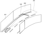
支援照射の幾つかの具体例を説明する。ここでは図2のように、自車両100の走行中の道路が直線道路から曲線道路(横方向に湾曲した道路)に変化する状況、すなわち、自車両100が直線道路から曲線道路に進入する状況を想定する。また、直線道路には直線的な側壁である直線側壁201が存在し、曲線道路には曲線道路に沿った曲線的な側壁である曲線側壁202が存在する。さらに、ヘッドライト21は点灯状態であり(図2には、ヘッドライト21から照射されたヘッドライト光101が示されている)、明るさ判定部13は、自車両100の周囲の明るさが、支援照射の実施が必要な明るさであると判定している。このように、図2の状況は、自車両100が走行中の道路に側壁(直線側壁201および曲線側壁202)が存在し、当該道路が湾曲しており、且つ、自車両100の周囲の明るさが支援照射の実施が必要な明るさと判定された状況である。よって、支援照射判断部14は、支援照射を実施すると判断し、支援照射制御部15により支援照射が実施される。
図2には、支援照射の例として、自車両100の前方の路面に、自車両100の進行方向に対して垂直に延びる1本のバー状(横棒状)の照射パターン102が照射される例が示されている。照射パターン102は、その一部が曲線側壁202に照射される。自車両100から見て、照射パターン102が路面上を延びる方向は路面に水平であるが、照射パターン102が曲線側壁202上を延びる方向は路面に対して傾いて見えるため、自車両100の運転者は、傾いて見える照射パターン102の位置から、曲線側壁202の存在を認知できる。照射パターン102の照射位置は、自車両100から一定距離(例えば30m)だけ前方でよい。照射パターン102の照射位置を自車両100から一定距離の位置とした場合、運転支援装置105による照射位置の制御を簡素化できる。
バー状の照射パターン102は複数本であってもよい。このとき、図3のように、直線側壁201に照射される照射パターン102と、曲線側壁202に照射される照射パターン102とで照射態様を変えてもよい。その場合、曲線側壁202に照射される照射パターン102が、直線側壁201に照射される照射パターン102よりも目立つ(視認性が高い)態様であることが好ましい。具体的には、曲線側壁202に照射される照射パターン102の幅を、直線側壁201に照射される照射パターン102の幅よりも広くする、曲線側壁202に照射される照射パターン102の間隔を、直線側壁201に照射される照射パターン102の間隔よりも狭くする、曲線側壁202に照射される照射パターン102の色調を、直線側壁201に照射される照射パターン102の色調よりも明るくする、などが考えられる。
バー状の照射パターン102において、路面に照射される部分と側壁に照射される部分とで、照射態様を変えてもよい。例えば、照射パターン102の路面に照射される部分と側壁に照射される部分とで、色調や太さなどを変えてもよい。照射パターン102の路面に照射される部分と側壁に照射される部分とが区別しやすくなり、自車両100の運転者は、曲線側壁202の存在をさらに認知しやすくなる。
バー状の照射パターン102の幅は、道路が直線のときに側壁ぎりぎりまで届く幅にしてもよい。その場合、照射パターン102は、曲線側壁202には届くが、直線側壁201には届かない。よって、運転者は、傾いて見える照射パターン102の有無によって、直線側壁201と曲線側壁202とを区別できる。ただし、直線側壁201に届かない照射パターン102は、直線道路が縦方向に湾曲した状況を示すことが困難であるため、道路の横方向の湾曲を示す場合に特化したものといえる。
照射パターン102は、実線状(連続的な線状)のパターンでなく、破線状や点線状のパターンでもよい。例えば、バー状の照射パターン102は、側壁およびその近傍に照射され、道路の中央部には照射されないパターンでもよい。
照射パターン102は、自車両100の進行方向に沿って延びるライン状(縦棒状)であってもよい。図4に、自車両100の前方の路面に、自車両100の進行方向に沿って延びる1本のライン状の照射パターン102が照射される支援照射の例を示す。
照射パターン102は、バー状のパターンとライン状のパターンとを組み合わせてなるパターンでもよい。図5に、自車両100の前方の路面に、1本のバー状のパターンと1本のライン状のパターンとを組み合わせてなる十字形の照射パターン102が照射される支援照射の例を示す。また、照射パターン102は、1本のライン状のパターンと、それに交差する複数本のバー状のパターンとを組み合わせてなるパターンでもよい。バー状のパターンとライン状のパターンとを組み合わせてなる照射パターン102は、高速道路のインターチェンジなど、カーブが長く続く螺旋状の道路で有効である。
このように、実施の形態1に係る運転支援装置10によれば、道路の側壁への支援照射光の照射によって、運転者に対し、湾曲した道路の形状の認知を促すことができる。よって、道路の形状に対する運転者の認知度を向上させることができる。その結果、自車両100が側壁に衝突するおそれを低減させ、安全運転に寄与できる。
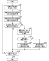
図6は、実施の形態1に係る運転支援装置10の動作を示すフローチャートである。以下、図6のフローチャートを参照しつつ、運転支援装置10の動作を説明する。
運転支援装置10が起動して、自車両100が走行を開始すると、明るさ判定部13は、ヘッドライト21の使用状況に基づいて、自車両100の周囲の明るさが、支援照射の実施が必要な明るさか否かを判定する(ステップS101)。
道路形状情報取得部11は、測位装置32が測定した自車両100の位置と地図データベース31内の地図データとを照合して自車両100が走行中の道路を特定し、地図データベース31から、自車両100が走行中の道路の形状の情報を取得する(ステップS102)。
側壁情報取得部12は、周辺検出装置33から、自車両100が走行中の道路に側壁が存在するか否かの情報を取得する(ステップS103)。
支援照射判断部14は、ステップS101~S103で取得された情報に基づいて、支援照射を実施するための条件(支援照射実施条件)が満たされているか否かを判断する(ステップS104)。具体的には、支援照射判断部14は、自車両100が走行中の道路に側壁が存在し、当該道路が横方向または縦方向に湾曲しており、且つ、自車両100の周囲の明るさが支援照射の実施が必要な明るさと判定された場合に、支援照射を実施すると判断する。
支援照射実施条件が満たされていれば(ステップS104でYES)、支援照射制御部15が、サブライト22を制御して支援照射を実行する(ステップS105)。支援照射実施条件が満たされていなければ(ステップS104でNO)、支援照射は実施されない。
その後、運転支援装置10は、自車両100の走行が終了したか否かを確認する(ステップS106)。自車両100の走行が継続していれば(ステップS106でNO)、ステップS101へ戻り、自車両100の走行が終了すれば(ステップS106でYES)、運転支援装置10の動作は終了する。
[変形例]
支援照射は、横方向に広がりを持ち縦方向には広がりを持たない扇形の光を、水平方向(一定の高さ方向)に照射することによって行われてもよい。この場合、図7および図8に示すように、照射パターン102は路面には照射されず、曲線側壁202に、水平方向に延びる直線状の照射パターン102が照射される。図2~図5のように照射パターン102が路面に照射される場合に比べ、自車両100の運転者が照射パターン102を煩わしく感じることを抑制できる。ただし、照射パターン102が路面に照射されない場合は、道路の路面と側壁との境界を運転者に認知させる効果が小さくなる点に留意すべきである。
支援照射は、横方向に広がりを持ち縦方向には広がりを持たない扇形の光を、水平方向(一定の高さ方向)に照射することによって行われてもよい。この場合、図7および図8に示すように、照射パターン102は路面には照射されず、曲線側壁202に、水平方向に延びる直線状の照射パターン102が照射される。図2~図5のように照射パターン102が路面に照射される場合に比べ、自車両100の運転者が照射パターン102を煩わしく感じることを抑制できる。ただし、照射パターン102が路面に照射されない場合は、道路の路面と側壁との境界を運転者に認知させる効果が小さくなる点に留意すべきである。
また、支援照射は、図9~図11に示すように、複数の照射パターン102を側壁に照射することによって行われてもよい。図9は照射パターン102が矢印形のパターンである例、図10は照射パターン102がL字形のパターンである例、図11は照射パターン102が円盤形のパターンである例をそれぞれ示している。これらの照射パターン102は、道路の形状の認知を促す道路構造物(例えば、側壁に設置される反射板やLED照明など)を模したものであり、側壁との相性がよく、照射パターン102が自車両100の運転者に違和感を与えることを抑制できる。
照射パターン102には、点滅、色の変化、位置の変化など、時間とともに態様が変化するアニメーション効果を付してもよい。また、照射パターン102は1つの点状のパターンでもよい。また、照射パターン102のアニメーション効果は、道路の曲率が小さいときに付されることが好ましい。
照射パターン102の態様を、自車両100が走行中の道路の形状に応じて変化させてもよい。例えば、道路の曲率が高いときほど、照射パターン102を目立つ態様にしてもよい。具体的には、道路の曲率が高いときほど、バー状の照射パターン102の幅を広くしたり、本数を増やしたり、密度を高くしたりしてもよい。
図12~図15は、道路が縦方向に湾曲していることを示すのに適した支援照射の例である。例えば、自車両100が下り坂に差し掛かるときには、図12および図13のように、上に凸の曲線に沿うように並ぶ複数の矢印形の照射パターン102を側壁に照射してもよい。逆に、上り坂に差し掛かるときには、上に凸の曲線に沿うように並ぶ複数の矢印形の照射パターン102を側壁に照射してもよい。
また、自車両100が下り坂に差し掛かるときには、図14および図15のように、複数の下向きの矢印形の照射パターン102を、側壁に照射してもよい。逆に、上り坂に差し掛かるときには、複数の上向きの矢印形の照射パターン102を側壁に照射してもよい。複数の矢印形の照射パターン102は、路面から一定の高さの位置に照射されてもよい。
自車両100の走行速度に応じて、照射パターン102の照射位置や態様を変化させてもよい。例えば、自車両100が3秒後に到達する位置に、照射パターン102が照射されるように、照射パターン102の照射位置が制御されてもよい。また、自車両100の走行速度が速いときほど、照射パターン102が目立つ態様となるように、照射パターン102の態様が制御されてもよい。
自車両100が走行中の道路の形状と、自車両100の走行速度との両方を考慮して、照射パターン102の照射位置や態様を変化させてもよい。
<実施の形態2>
図16は、実施の形態2に係る車両システム1の構成を示す図である。図16の車両システム1の構成は、図1の構成に対し、運転支援装置10に画像認識装置34を接続させるとともに、運転支援装置10内に認知度推定部16を追加したものである。
図16は、実施の形態2に係る車両システム1の構成を示す図である。図16の車両システム1の構成は、図1の構成に対し、運転支援装置10に画像認識装置34を接続させるとともに、運転支援装置10内に認知度推定部16を追加したものである。
画像認識装置34は、自車両100の車載カメラ(不図示)が撮影した運転支援装置10の周囲の画像を解析し、自車両100が走行中の道路および側壁の色調(例えば、色相、彩度、明度など)を認識する。
認知度推定部16は、画像認識装置34から自車両100が走行中の道路の側壁および路面の色調の情報を取得し、側壁と路面との色調の差に基づいて、道路の形状に対する運転者の認知度を推定する。通常、側壁と路面との色調差が小さいとき、運転者が道路の形状を認知することが困難になる。そのため、認知度推定部16は、側壁と路面との色調差が小さいときは、道路形状に対する運転者の認知度は低いと推定し、側壁と路面との色調差が大きいときは、道路形状に対する運転者の認知度は高いと推定する。
また、実施の形態2では、支援照射制御部15は、認知度推定部16が推定した道路形状に対する運転者の認知度が予め定められた閾値以上のときは、支援照射を実施しないと判断する。
認知度推定部16は、自車両100の前方の予め定められた範囲における、路面と側壁との色調差の平均値を、側壁と路面との色調差として算出するとよい。本実施の形態では、認知度推定部16は、自車両100が2秒後から3秒後までの間に通過する範囲における、路面と側壁との色調差の平均値を、側壁と路面との色調差として算出するものとする。この場合、自車両100が2秒後に到達する距離をL2、自車両100が3秒後に到達する距離をL3、L=L3-L2とすると、路面と側壁との色調差Dは、次の式で算出される。
D=∫|Cdri(r)-Cdwi(r)|/L (r=L2~L3)
この式において、rは自車両100からの距離、Cdri(r)は距離rにおける路面の色調、Cdwi(r)は距離rにおける側壁の色調である。
D=∫|Cdri(r)-Cdwi(r)|/L (r=L2~L3)
この式において、rは自車両100からの距離、Cdri(r)は距離rにおける路面の色調、Cdwi(r)は距離rにおける側壁の色調である。
色調差の平均値をとる範囲は、2秒後~3秒後の範囲より広くてもよい。あるいは、2秒後~3秒後の範囲より広い範囲で色調差を求め、そのうちの2秒後~3秒後の範囲における色調差の重みを大きくした加重平均を、側壁と路面との色調差として算出してもよい。
色調差の算出に用いる色調のパラメータは、色相、彩度、明度のいずれか1つ、あるいは2つ以上のパラメータでもよいし、それ以外の他のパラメータでもよい。例えば、自車両100の周囲の画像における路面と側壁とのコントラスト値から色調差を算出してもよい。
図17は、実施の形態2に係る運転支援装置10の動作を示すフローチャートである。図17のフローチャートは、図6に対し、ステップS104とステップS105との間にステップS201およびS202を追加したものである。
ステップS201は、ステップS104で支援照射を実施するための条件(支援照射実施条件)が満たされていると判断された場合(ステップS104でYESの場合)に行われる。ステップS201では、認知度推定部16が、画像認識装置34から取得した自車両100が走行中の道路の側壁および路面の色調の情報から、側壁と路面との色調の差を算出し、道路形状に対する運転者の認知度を推定する。
ステップS202は、ステップS201の後に行われる。ステップS202では、支援照射判断部14が、ステップS201で推定された認知度が予め定められた閾値未満か否かを確認する。認知度が閾値未満であれば(ステップS202でYES)、支援照射判断部14は支援照射を実施すると判断し、ステップS105にて支援照射が実施される。しかし、認知度が閾値以上であれば(ステップS202でNO)、支援照射判断部14は、支援照射の実施は不要と判断し、支援照射は実施されずにステップS106へ進む。
実施の形態2に係る運転支援装置10によれば、道路形状に対する運転者の認知度が高いときに不要な支援照射が実施されないため、運転者が支援照射を煩わしく感じることを抑制できるとともに、消費電力の削減に寄与できる。
[変形例]
実施の形態2では、認知度推定部16が、道路形状に対する運転者の認知度を、道路の側壁および路面の色調差に基づいて推定する例を示したが、道路形状に対する認知度の推定方法はこれに限られない。
実施の形態2では、認知度推定部16が、道路形状に対する運転者の認知度を、道路の側壁および路面の色調差に基づいて推定する例を示したが、道路形状に対する認知度の推定方法はこれに限られない。
道路上の区画線は、運転者が道路形状を認知するための手段の一つである。よって、認知度推定部16は、道路と区画線との色調差に基づいて、道路形状に対する運転者の認知度を推定してもよい。道路と区画線との色調差は、例えば、車載カメラが撮影した自車両100の周辺の画像を解析することにより算出できる。
また、周囲が暗くなると、運転者が道路形状を認知するのが難しくなる。よって、認知度推定部16は、自車両100の周辺の明るさに基づいて、道路形状に対する運転者の認知度を推定してもよい。周囲の明るさは、例えば、車載カメラが撮影した自車両100の周辺の画像を解析することにより算出してもよいし、照度計で実測してもよい。
また、道路の形状の認知を促す道路構造物(例えば、側壁に設置される反射板やLED照明など)が設置されている場合には、運転者が道路形状を容易に認知できる。よって、認知度推定部16は、道路構造物の有無に基づいて、道路形状に対する運転者の認知度を推定してもよい。道路構造物の有無は、例えば、車載カメラが撮影した自車両100の周辺の画像を解析することにより判断できる。
認知度推定部16は、運転者の視覚能力から、道路形状に対する運転者の認知度を推定してもよい。運転者の視覚能力は、認知度推定部16が、任意の方法で推定してもよい。例えば、認知度推定部16が、ドライバーモニタリングシステム(DMS)を利用して、運転者による自車両100の操作状況を監視し、誤操作や急な運転操作(急ハンドル、急ブレーキなど)の発生の頻度が高い場合は運転者の視覚能力は低いと推定してもよい。また、認知度推定部16が、DMSを利用して運転者の心理状態または生理状態を検出し、運転者の疲労度が高い場合や、覚醒度が低い場合、視線が定まらずキョロキョロしている場合などには、実質的な視覚能力が低下していると推定してもよい。また、運転者が自己の資格能力を示す情報(例えば、視力、白内障の有無など)を、認知度推定部16に予め入力できるようにしてもよい。
認知度推定部16は、上記の方法の2つ以上を組み合わせて、道路形状に対する運転者の認知度を推定してもよい。
<実施の形態3>
実施の形態3に係る車両システム1の構成は、実施の形態2(図16)と同様である。実施の形態3に係る運転支援装置10においては、認知度推定部16が推定した道路形状に対する運転者の認知度に応じて、支援照射制御部15が支援照射の態様を変更する。具体的には、支援照射制御部15は、道路形状に対する運転者の認知度が低いときほど、支援照射をより目立つ態様(視認性の高い態様)で実施する。
実施の形態3に係る車両システム1の構成は、実施の形態2(図16)と同様である。実施の形態3に係る運転支援装置10においては、認知度推定部16が推定した道路形状に対する運転者の認知度に応じて、支援照射制御部15が支援照射の態様を変更する。具体的には、支援照射制御部15は、道路形状に対する運転者の認知度が低いときほど、支援照射をより目立つ態様(視認性の高い態様)で実施する。
図18は、実施の形態3に係る運転支援装置10の動作を示すフローチャートである。図18のフローチャートは、図17に対し、ステップS105をステップS301およびS302に置き換えたものである。
ステップS301は、ステップS202において道路形状に対する運転者の認知度が閾値以上と判断された場合(ステップS202でNOの場合)に行われる。道路形状に対する運転者の認知度が高いときは、目立つ態様の支援照射を行う必要性は低いため、ステップS301では、支援照射制御部15が、控えめな態様(視認性の低い態様)である第1の態様で支援照射を実施する。これにより、運転者が支援照射を煩わしく感じることが抑制される。
ステップS302は、ステップS202において道路形状に対する運転者の認知度が閾値未満と判断された場合(ステップS202でYESの場合)に行われる。道路形状に対する運転者の認知度が低いときは、目立つ態様の支援照射を行う必要性が高いため、ステップS302では、支援照射制御部15が、目立つ態様である第2の態様で支援照射を実施する。これにより、道路形状に対する運転者の認知度を効果的に向上させる。
例えば、第2の態様の支援照射における照射パターンのサイズを、第1の態様の支援照射における照射パターンのサイズよりも大きくする、第2の態様の支援照射における照射パターンの色調を、第2の態様の支援照射における照射パターンの色調よりも明るくする、などが考えられる。
実施の形態3に係る運転支援装置10によれば、道路形状に対する運転者の認知度に応じた適切な支援照射を実施することができる。
[変形例]
実施の形態3では、道路形状に対する運転者の認知度に応じて、支援照射制御部15が、2種類の支援照射を切り替える例を示したが、認知度の閾値を2つ以上設けて認知度を細分化し、支援照射制御部15が、認知度の高さに応じて、3種類以上の支援照射を切り替えるようにしてもよい。あるいは、支援照射制御部15が、認知度の高さに応じて、支援照射の態様を連続的または多段階的に変化させてもよい。
実施の形態3では、道路形状に対する運転者の認知度に応じて、支援照射制御部15が、2種類の支援照射を切り替える例を示したが、認知度の閾値を2つ以上設けて認知度を細分化し、支援照射制御部15が、認知度の高さに応じて、3種類以上の支援照射を切り替えるようにしてもよい。あるいは、支援照射制御部15が、認知度の高さに応じて、支援照射の態様を連続的または多段階的に変化させてもよい。
例えば、道路形状に対する運転者の認知度が低い場合に、アニメーション効果が付された態様の支援照射が実施されてもよい。また、認知度が低くなるほど、アニメーションの変化速度や変化量を大きくしてもよい。
支援照射の態様を連続的に変化させる場合、例えば、照射パターンのサイズを連続的に変化させてもよいし、アニメーションの変化量を連続的に変化させてもよい。
<ハードウェア構成例>
図19および図20は、それぞれ運転支援装置10のハードウェア構成の例を示す図である。図1に示した運転支援装置10の構成要素の各機能は、例えば図19に示す処理回路50により実現される。すなわち、運転支援装置10は、自車両100が走行中の道路の形状の情報を取得し、道路に側壁が存在するか否かの情報を取得し、自車両100の周囲の明るさが、自車両100の運転者に道路の形状の認知を促す光の照射である支援照射の実施が必要な明るさか否かを判定し、道路の側壁の有無、道路の形状、および、自車両100の周囲の明るさの判定結果に基づいて、支援照射を実施するか否かを判断し、支援照射を実施すると判断されたときに、自車両100の灯火装置20を制御して支援照射を実施するための処理回路50を備える。処理回路50は、道路に側壁が存在し、当該道路が横方向または縦方向に湾曲しており、且つ、自車両100の周囲の明るさが支援照射の実施が必要な明るさと判定された場合に、支援照射を実施すると判断し、光の少なくとも一部を道路の側壁に照射することによって支援照射を実施する。
図19および図20は、それぞれ運転支援装置10のハードウェア構成の例を示す図である。図1に示した運転支援装置10の構成要素の各機能は、例えば図19に示す処理回路50により実現される。すなわち、運転支援装置10は、自車両100が走行中の道路の形状の情報を取得し、道路に側壁が存在するか否かの情報を取得し、自車両100の周囲の明るさが、自車両100の運転者に道路の形状の認知を促す光の照射である支援照射の実施が必要な明るさか否かを判定し、道路の側壁の有無、道路の形状、および、自車両100の周囲の明るさの判定結果に基づいて、支援照射を実施するか否かを判断し、支援照射を実施すると判断されたときに、自車両100の灯火装置20を制御して支援照射を実施するための処理回路50を備える。処理回路50は、道路に側壁が存在し、当該道路が横方向または縦方向に湾曲しており、且つ、自車両100の周囲の明るさが支援照射の実施が必要な明るさと判定された場合に、支援照射を実施すると判断し、光の少なくとも一部を道路の側壁に照射することによって支援照射を実施する。
処理回路50は、専用のハードウェアであってもよいし、メモリに格納されたプログラムを実行するプロセッサ(中央処理装置(CPU:Central Processing Unit)、処理装置、演算装置、マイクロプロセッサ、マイクロコンピュータ、DSP(Digital Signal Processor)とも呼ばれる)を用いて構成されていてもよい。
処理回路50が専用のハードウェアである場合、処理回路50は、例えば、単一回路、複合回路、プログラム化したプロセッサ、並列プログラム化したプロセッサ、ASIC(Application Specific Integrated Circuit)、FPGA(Field-Programmable Gate Array)、またはこれらを組み合わせたものなどが該当する。運転支援装置10の構成要素の各々の機能が個別の処理回路で実現されてもよいし、それらの機能がまとめて一つの処理回路で実現されてもよい。
図20は、処理回路50がプログラムを実行するプロセッサ51を用いて構成されている場合における運転支援装置10のハードウェア構成の例を示している。この場合、運転支援装置10の構成要素の機能は、ソフトウェア等(ソフトウェア、ファームウェア、またはソフトウェアとファームウェアとの組み合わせ)により実現される。ソフトウェア等はプログラムとして記述され、メモリ52に格納される。プロセッサ51は、メモリ52に記憶されたプログラムを読み出して実行することにより、各部の機能を実現する。すなわち、運転支援装置10は、プロセッサ51により実行されるときに、自車両100が走行中の道路の形状の情報を取得する処理と、道路に側壁が存在するか否かの情報を取得する処理と、自車両100の周囲の明るさが、自車両100の運転者に道路の形状の認知を促す光の照射である支援照射の実施が必要な明るさか否かを判定する処理と、道路の側壁の有無、道路の形状、および、自車両100の周囲の明るさの判定結果に基づいて、支援照射を実施するか否かを判断する処理と、支援照射を実施すると判断されたときに、自車両100の灯火装置20を制御して支援照射を実施する処理と、が結果的に実行されることになるプログラムを格納するためのメモリ52を備える。当該プログラムを実行するプロセッサ51は、道路に側壁が存在し、当該道路が横方向または縦方向に湾曲しており、且つ、自車両100の周囲の明るさが支援照射の実施が必要な明るさと判定された場合に、支援照射を実施すると判断し、光の少なくとも一部を道路の側壁に照射することによって支援照射を実施する。換言すれば、このプログラムは、運転支援装置10の構成要素の動作の手順や方法をコンピュータに実行させるものであるともいえる。
ここで、メモリ52は、例えば、RAM(Random Access Memory)、ROM(Read Only Memory)、フラッシュメモリ、EPROM(Erasable Programmable Read Only Memory)、EEPROM(Electrically Erasable Programmable Read Only Memory)などの、不揮発性または揮発性の半導体メモリ、HDD(Hard Disk Drive)、磁気ディスク、フレキシブルディスク、光ディスク、コンパクトディスク、ミニディスク、DVD(Digital Versatile Disc)およびそのドライブ装置のほか、今後使用されるあらゆる記憶媒体であってもよい。
以上、運転支援装置10の構成要素の機能が、ハードウェアおよびソフトウェア等のいずれか一方で実現される構成について説明した。しかしこれに限ったものではなく、運転支援装置10の一部の構成要素を専用のハードウェアで実現し、別の一部の構成要素をソフトウェア等で実現する構成であってもよい。例えば、一部の構成要素については専用のハードウェアとしての処理回路50でその機能を実現し、他の一部の構成要素についてはプロセッサ51としての処理回路50がメモリ52に格納されたプログラムを読み出して実行することによってその機能を実現することが可能である。
以上のように、運転支援装置10は、ハードウェア、ソフトウェア等、またはこれらの組み合わせによって、上述の各機能を実現することができる。
なお、各実施の形態を自由に組み合わせたり、各実施の形態を適宜、変形、省略したりすることが可能である。
上記した説明は、すべての態様において、例示であって、例示されていない無数の変形例が想定され得るものと解される。
1 車両システム、10 運転支援装置、11 道路形状情報取得部、12 側壁情報取得部、13 明るさ判定部、14 支援照射判断部、15 支援照射制御部、16 認知度推定部、20 灯火装置、21 ヘッドライト、22 サブライト、31 地図データベース、32 測位装置、33 周辺検出装置、34 画像認識装置、50 処理回路、51 プロセッサ、52 メモリ、100 自車両、101 ヘッドライト光、102 照射パターン、201 直線側壁、202 曲線側壁。
Claims (18)
- 自車両が走行中の道路の形状の情報を取得する道路形状情報取得部と、
前記道路に側壁が存在するか否かの情報を取得する側壁情報取得部と、
前記自車両の周囲の明るさが、前記自車両の運転者に前記道路の形状の認知を促す光の照射である支援照射の実施が必要な明るさか否かを判定する明るさ判定部と、
前記道路の前記側壁の有無、前記道路の形状、および、前記自車両の周囲の明るさの判定結果に基づいて、前記支援照射を実施するか否かを判断する支援照射判断部と、
前記支援照射を実施すると判断されたときに、前記自車両の灯火装置を制御して前記支援照射を実施する支援照射制御部と、
を備え、
前記支援照射判断部は、前記道路に前記側壁が存在し、当該道路が横方向または縦方向に湾曲しており、且つ、前記自車両の周囲の明るさが前記支援照射の実施が必要な明るさと判定された場合に、前記支援照射を実施すると判断し、
前記支援照射制御部は、前記光の少なくとも一部を前記道路の前記側壁に照射することによって前記支援照射を実施する、
運転支援装置。 - 前記道路の形状に対する前記運転者の認知度を推定する認知度推定部をさらに備え、
前記支援照射判断部は、前記認知度が予め定められた閾値未満のときは、前記支援照射を実施しないと判断する、
請求項1に記載の運転支援装置。 - 前記認知度推定部は、前記道路の前記側壁と路面と色調の差に基づいて前記認知度を推定する、
請求項2に記載の運転支援装置。 - 前記認知度推定部は、前記運転者の視覚能力に基づいて前記認知度を推定する、
請求項2に記載の運転支援装置。 - 前記認知度推定部は、前記道路の区画線と路面との色調の差に基づいて前記認知度を推定する、
請求項2に記載の運転支援装置。 - 前記認知度推定部は、前記道路にその道路の形状の認知を促す道路構造物が存在するか否かに基づいて前記認知度を推定する、
請求項2に記載の運転支援装置。 - 前記道路の形状に対する前記運転者の認知度を推定する認知度推定部をさらに備え、
前記支援照射制御部は、前記認知度が低いときほど前記支援照射をより目立つ態様で実施する、
請求項1に記載の運転支援装置。 - 前記認知度推定部は、前記道路の前記側壁と路面と色調の差に基づいて前記認知度を推定する、
請求項7に記載の運転支援装置。 - 前記認知度推定部は、前記運転者の視覚能力に基づいて前記認知度を推定する、
請求項7に記載の運転支援装置。 - 前記認知度推定部は、前記道路の区画線と路面との色調の差に基づいて前記認知度を推定する、
請求項7に記載の運転支援装置。 - 前記認知度推定部は、前記道路にその道路の形状の認知を促す道路構造物が存在するか否かに基づいて前記認知度を推定する、
請求項7に記載の運転支援装置。 - 前記支援照射は、前記道路の前記側壁または路面に点状または線状の照射パターンを照射することによって実施される、
請求項1に記載の運転支援装置。 - 点状の前記照射パターンは前記道路の前記側壁に照射され、線状の前記照射パターンは前記道路の前記側壁あるいは前記道路の前記側壁および前記路面に照射される、
請求項12記載の運転支援装置。 - 前記照射パターンは、道路の形状の認知を促す道路構造物を模したものである、
請求項12記載の運転支援装置。 - 前記支援照射制御部は、前記道路の前記側壁に照射した点状の前記照射パターンの態様を時間とともに変化させる、
請求項12記載の運転支援装置。 - 前記支援照射制御部は、前記道路の形状に応じて前記支援照射の態様を変化させる、
請求項1に記載の運転支援装置。 - 前記支援照射制御部は、前記自車両の走行速度に応じて前記支援照射の態様を変化させる、
請求項1に記載の運転支援装置。 - 運転支援装置の道路形状情報取得部が、自車両が走行中の道路の形状の情報を取得し、
前記運転支援装置の側壁情報取得部が、前記道路に側壁が存在するか否かの情報を取得し、
前記運転支援装置の明るさ判定部が、前記自車両の周囲の明るさが、前記自車両の運転者に前記道路の形状の認知を促す光の照射である支援照射の実施が必要な明るさか否かを判定し、
前記運転支援装置の支援照射判断部が、前記道路の前記側壁の有無、前記道路の形状、および、前記自車両の周囲の明るさの判定結果に基づいて、前記支援照射を実施するか否かを判断し、
前記支援照射を実施すると判断されたときに、前記運転支援装置の支援照射制御部が、前記自車両の灯火装置を制御して前記支援照射を実施し、
前記支援照射判断部は、前記道路に前記側壁が存在し、当該道路が横方向または縦方向に湾曲しており、且つ、前記自車両の周囲の明るさが前記支援照射の実施が必要な明るさと判定された場合に、前記支援照射を実施すると判断し、
前記支援照射制御部は、前記光の少なくとも一部を前記道路の前記側壁に照射することによって前記支援照射を実施する、
運転支援方法。
Priority Applications (2)
| Application Number | Priority Date | Filing Date | Title |
|---|---|---|---|
| PCT/JP2023/021342 WO2024252614A1 (ja) | 2023-06-08 | 2023-06-08 | 運転支援装置および運転支援方法 |
| JP2025525859A JP7721043B2 (ja) | 2023-06-08 | 2023-06-08 | 運転支援装置および運転支援方法 |
Applications Claiming Priority (1)
| Application Number | Priority Date | Filing Date | Title |
|---|---|---|---|
| PCT/JP2023/021342 WO2024252614A1 (ja) | 2023-06-08 | 2023-06-08 | 運転支援装置および運転支援方法 |
Publications (1)
| Publication Number | Publication Date |
|---|---|
| WO2024252614A1 true WO2024252614A1 (ja) | 2024-12-12 |
Family
ID=93795709
Family Applications (1)
| Application Number | Title | Priority Date | Filing Date |
|---|---|---|---|
| PCT/JP2023/021342 Ceased WO2024252614A1 (ja) | 2023-06-08 | 2023-06-08 | 運転支援装置および運転支援方法 |
Country Status (2)
| Country | Link |
|---|---|
| JP (1) | JP7721043B2 (ja) |
| WO (1) | WO2024252614A1 (ja) |
Citations (3)
| Publication number | Priority date | Publication date | Assignee | Title |
|---|---|---|---|---|
| JP2005059839A (ja) * | 2003-07-28 | 2005-03-10 | Denso Corp | 車両用前照灯装置 |
| JP2018020683A (ja) * | 2016-08-04 | 2018-02-08 | トヨタ自動車株式会社 | 車両用照明装置 |
| WO2022254570A1 (ja) * | 2021-06-01 | 2022-12-08 | 三菱電機株式会社 | 投射制御装置および投射制御方法 |
-
2023
- 2023-06-08 JP JP2025525859A patent/JP7721043B2/ja active Active
- 2023-06-08 WO PCT/JP2023/021342 patent/WO2024252614A1/ja not_active Ceased
Patent Citations (3)
| Publication number | Priority date | Publication date | Assignee | Title |
|---|---|---|---|---|
| JP2005059839A (ja) * | 2003-07-28 | 2005-03-10 | Denso Corp | 車両用前照灯装置 |
| JP2018020683A (ja) * | 2016-08-04 | 2018-02-08 | トヨタ自動車株式会社 | 車両用照明装置 |
| WO2022254570A1 (ja) * | 2021-06-01 | 2022-12-08 | 三菱電機株式会社 | 投射制御装置および投射制御方法 |
Also Published As
| Publication number | Publication date |
|---|---|
| JPWO2024252614A1 (ja) | 2024-12-12 |
| JP7721043B2 (ja) | 2025-08-08 |
Similar Documents
| Publication | Publication Date | Title |
|---|---|---|
| JP3865574B2 (ja) | 車両用前照灯システム | |
| JP4730267B2 (ja) | 車両用視界状況判定装置 | |
| US8811668B2 (en) | Method for controlling a headlamp system for a vehicle, and headlamp system | |
| CN103874931B (zh) | 用于求取车辆的环境中的对象的位置的方法和设备 | |
| EP2594431B1 (en) | Apparatus and method for controlling a headlamp of vehicle | |
| JP2017159871A (ja) | 車両用照明装置 | |
| JP6929481B1 (ja) | 配光制御装置、配光制御方法及び配光制御プログラム | |
| US20060087416A1 (en) | Information providing device for vehicle | |
| JP5980899B2 (ja) | 車両用の照明システムのヘッドライトレンジを距離に応じて調整するための方法、制御装置、およびコンピュータ読み取り可能な記録媒体 | |
| US20160016504A1 (en) | Method and device for controlling a light emission of at least one headlight of a vehicle | |
| JP2002040139A (ja) | 物体認識方法及び装置、記録媒体 | |
| JP2002052975A (ja) | 車両用前照灯システム | |
| CN102673560A (zh) | 识别拐弯机动的方法和驾驶员辅助系统 | |
| EP3763578A1 (en) | Vehicle-mounted equipment control device | |
| JPWO2020008560A1 (ja) | 情報表示装置及び情報表示方法 | |
| JP2021088233A (ja) | 車両用投光制御装置、車両用投光システム、及び車両用投光制御方法 | |
| JP2000293782A (ja) | 自動走行制御装置 | |
| JP7466774B2 (ja) | 投射制御装置および投射制御方法 | |
| CN110316187B (zh) | 汽车及其避障控制方法 | |
| JP7378673B2 (ja) | 前照灯制御装置、前照灯制御システム、及び前照灯制御方法 | |
| JP7721043B2 (ja) | 運転支援装置および運転支援方法 | |
| JP5531919B2 (ja) | 前照灯制御装置 | |
| JP2000168437A (ja) | 車両用照明装置 | |
| JP2012196999A (ja) | 車両用照明装置及び方法 | |
| JP2002225618A (ja) | 車両用前照灯システム |
Legal Events
| Date | Code | Title | Description |
|---|---|---|---|
| 121 | Ep: the epo has been informed by wipo that ep was designated in this application |
Ref document number: 23940713 Country of ref document: EP Kind code of ref document: A1 |
|
| WWE | Wipo information: entry into national phase |
Ref document number: 2025525859 Country of ref document: JP |
|
| NENP | Non-entry into the national phase |
Ref country code: DE |